

Page 1

2-E
Page 2
SERIES
SERIES
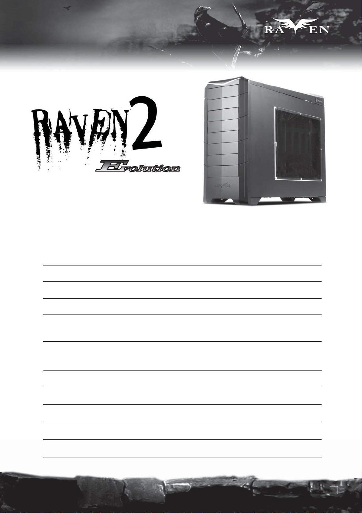
Revolutionary 90 degree motherboard
mounting from RAVEN RV01
Installation and system optimization guide:
The following manual and guides were carefully prepared by the RAVEN engineering team to help
you maximize the potential of your SilverStone product. Please keep this manual for future reference
when upgrading or performing maintenance on your system. A copy of this manual can also be
downloaded from our website at:
http://www.silverstonetek.com
Specifications
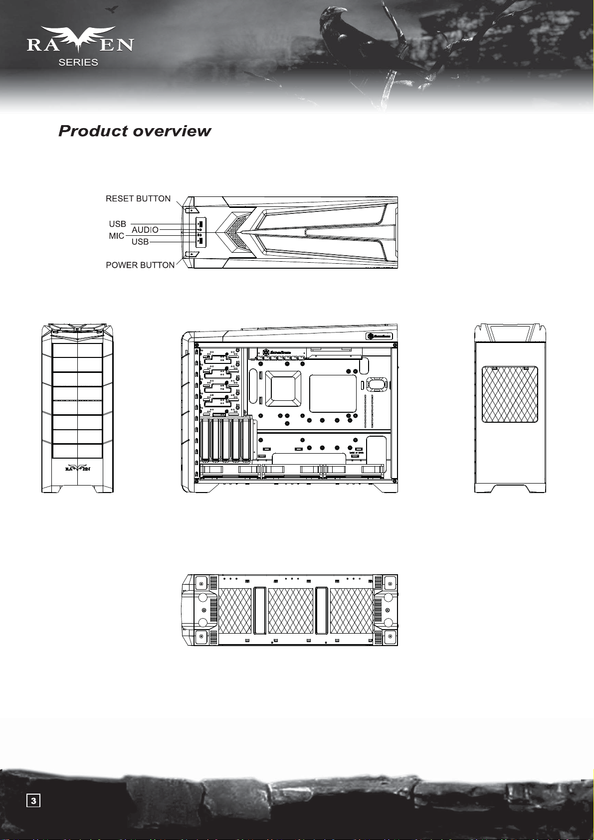
Product overview
Disassemble Chart
Installation guide
Connector definition
Liquid cooling installation guide
Component size limitations
Top cover limitation
P.2
P.3
P.4
P.5
P.17
P.21
P.25
P.30
Upgrade and maintenance
1
P.34
Page 3
Revolutionary 90 degree motherboard
mounting from RAVEN RV01
SERIES
SERIES
Specifications
Model
Material reinforced plastic outer shell, 0.8mm Steel body
SST-RV02B-E (black)
SST-RV02B-EW (black + window)
Matte black Color
Motherboard
Drive Bay
Cooling System
Expansion Slot
Front I/O Port
SSI CEB, ATX (maximum 12” x 11”) , Micro ATX
Exposed 5.25" x 5
Internal 3.5" x 5 , 2.5” x1
Bottom 3 x 180mm intake fan 700/1200rpm, 18/34dBA
Top 1 x 120mm exhaust fan, 950rpm, 18dBA
7
USB 3.0 x 2, Audio x 1, MIC x 1
Power Supply
Dimension
Expansion Card
1 x optional standard PS2 (ATX)
212mm (W) x 503mm (H) x 643mm (D)
Up to 12.2 inch
2
Page 4
Page 5
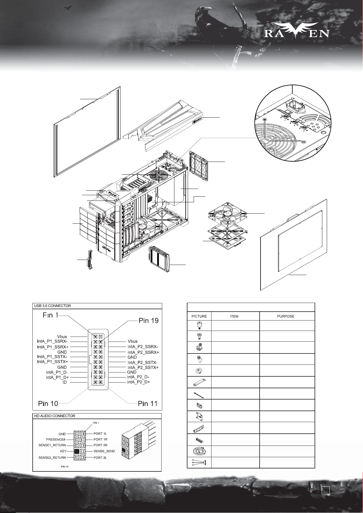
Disassemble Chart
LIFT SIDE PANEL
12025 FAN
TOP COVER
18032 FAN SWICTH x 3
PSU FILTER
SERIES
SERIES
RESWT SW
FRONT I/O
POWER SW
5.25” DRIVE BAY x 5
SILVERSTONE SST-CP05
FRONT I/O Pin Definition
PS2 PSU(OPTION)
180 FAN BRACKET
180 FAN FILTER
3.5” DEIVE BAY x 5
ATX MB(OPTION)
PACKAGE CONTENT
SCREW A
SCREW B
SCREW C
SCREW D
18032 FAN x 3
SECURE 5.25” DEVICE
SECURE HARD DRIVE
SECURE POWER SUPPLY OR
PSU BKT AND MOTHRBOARD
SECURE MOTHERBOARD
RIGHT SIDE PANEL-W
SCREW E
RADIATOR-BKT
BUNCH WIRE TIES
PSU BKT
2.5”HDD BKT
5.25” CHANGE 3.5PLATE
5.25” CHANGE 3.5BKT
BUNCH WIRE TIES
FAN CABLE
SECURE 5.25” DEVICE
SECURE RADIATOR
SECURE WIRE
SECURE POWER SUPPLY
SECURE 2.5”HARD DRIVE
SECURE FLOPPY
SECURE FLOPPY
SECURE POWER SUPPLY
SECURE FAN
4
Page 6
SERIES
SERIES
lnstallation Guide
Before you begin, please make sure that you
(1) have all components collected
(2) check that all components do not have compatibility problems with each other or with the case
(3) if possible, assemble the components outside the case first to make sure they are working
(4) keep the motherboard manual ready for reference during installation.
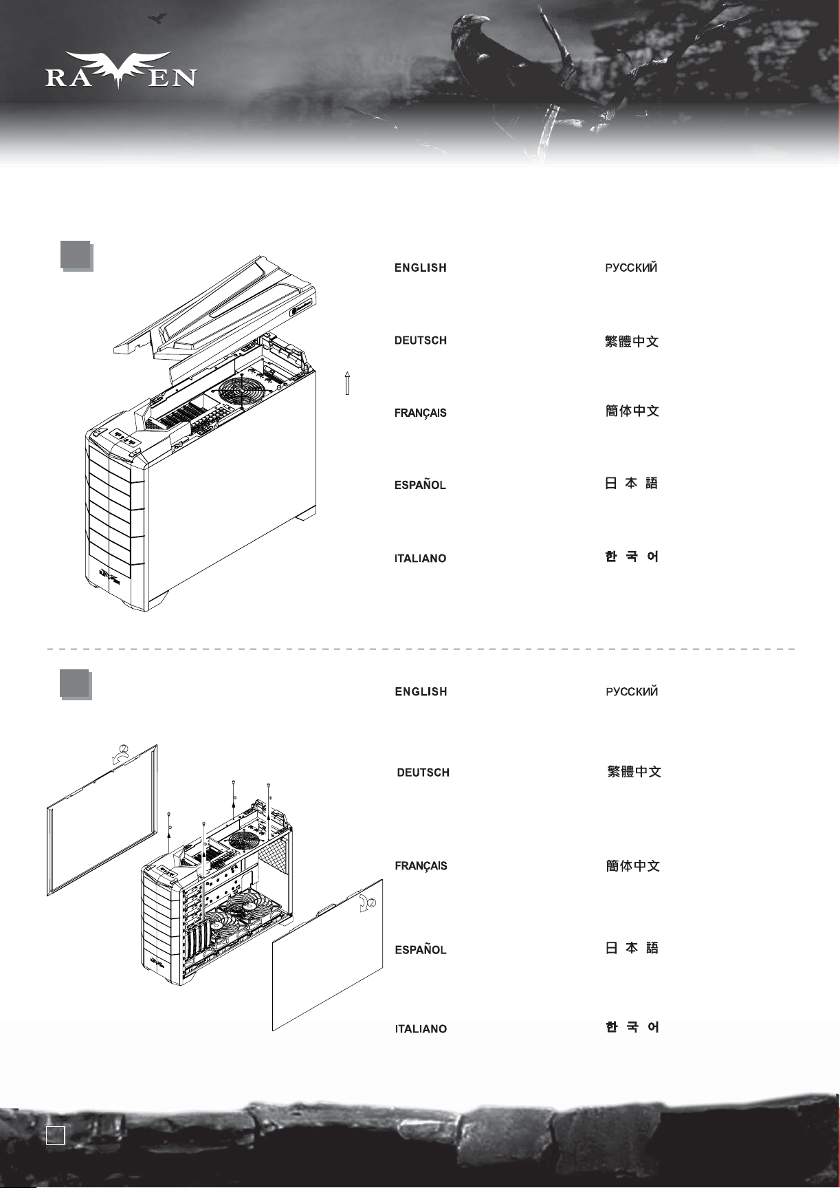
1
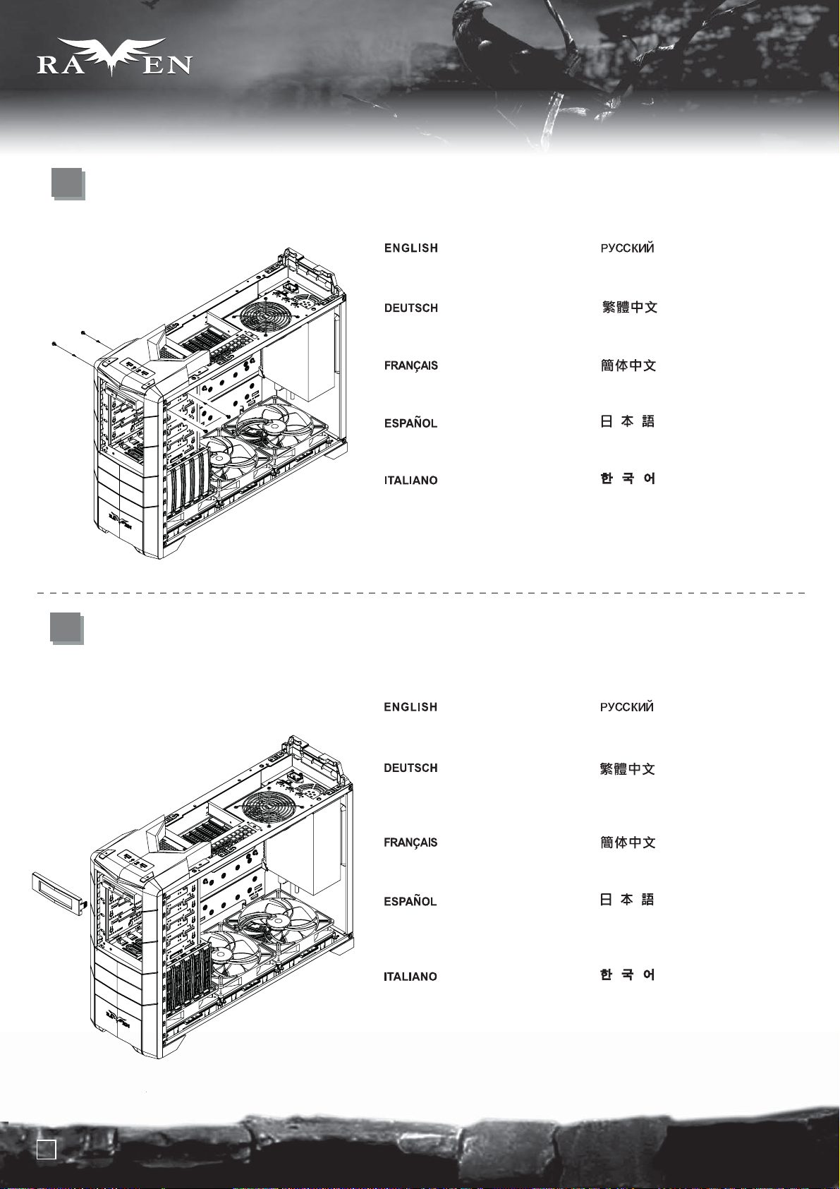
Pull top plastic cover off the case
in the direction as illustrated by
the arrow
Ziehen Sie die obere
Kunststoffabdeckung in Pfeilrichtung
vom Gehäuse ab (siehe Abbildung).
Tirer le cache en plastique supérieur
vers l'extérieur du boitier comme
illustré par la flèche
Quite la cubierta superior de plástico
de la carcasa en la dirección que
muestra la flecha.
Rimuovere il cover superiore in
plastica come mostrato in figura
Сдвиньте верхнюю пластиковую
крышку корпуса в направлении,
указанном стрелкой.
請按箭頭方向用力,取出塑膠上蓋.
请按箭头方向用力,取出塑胶上盖。
矢印で示される方向に、ケースからの一番
上のプラスチックカバーを抜き取ります。
상부의 플라스틱 커버를 화살표
방향과 같이 당겨서 제거 합니다.
2
Remove four thumb screws from the
top to pull the side panels away from
the case
Entfernen Sie die vier
Flügelschrauben von der Oberseite,
ziehen Sie die seitlichen Blenden
vom Gehäuse ab.
Retirer les quatre vis à main du
dessus pour retirer les panneaux
latéraux du boîtier
Quite los cuatro tornillos de la parte
superior para liberar los paneles
laterales de la carcasa.
Svitare le 4 viti sulla parte superiore
per rimuovere i pannelli laterali
Чтобы снять боковые панели
корпуса, открутите сверху четыре
винта с рифлёной головкой.
先鬆開四顆手扭螺絲,
再旋轉取出左右側板.
先松开四颗手扭螺丝,
再旋转取出左右侧板。
ケースから側面パネルを取り外すため、
つまみネジ4本を上部から外します。
싸이드 패널을 케이스에서
제거하기위해 4개의 손나사를
상부에서 제거합니다.
5
Page 7
lnstallation Guide
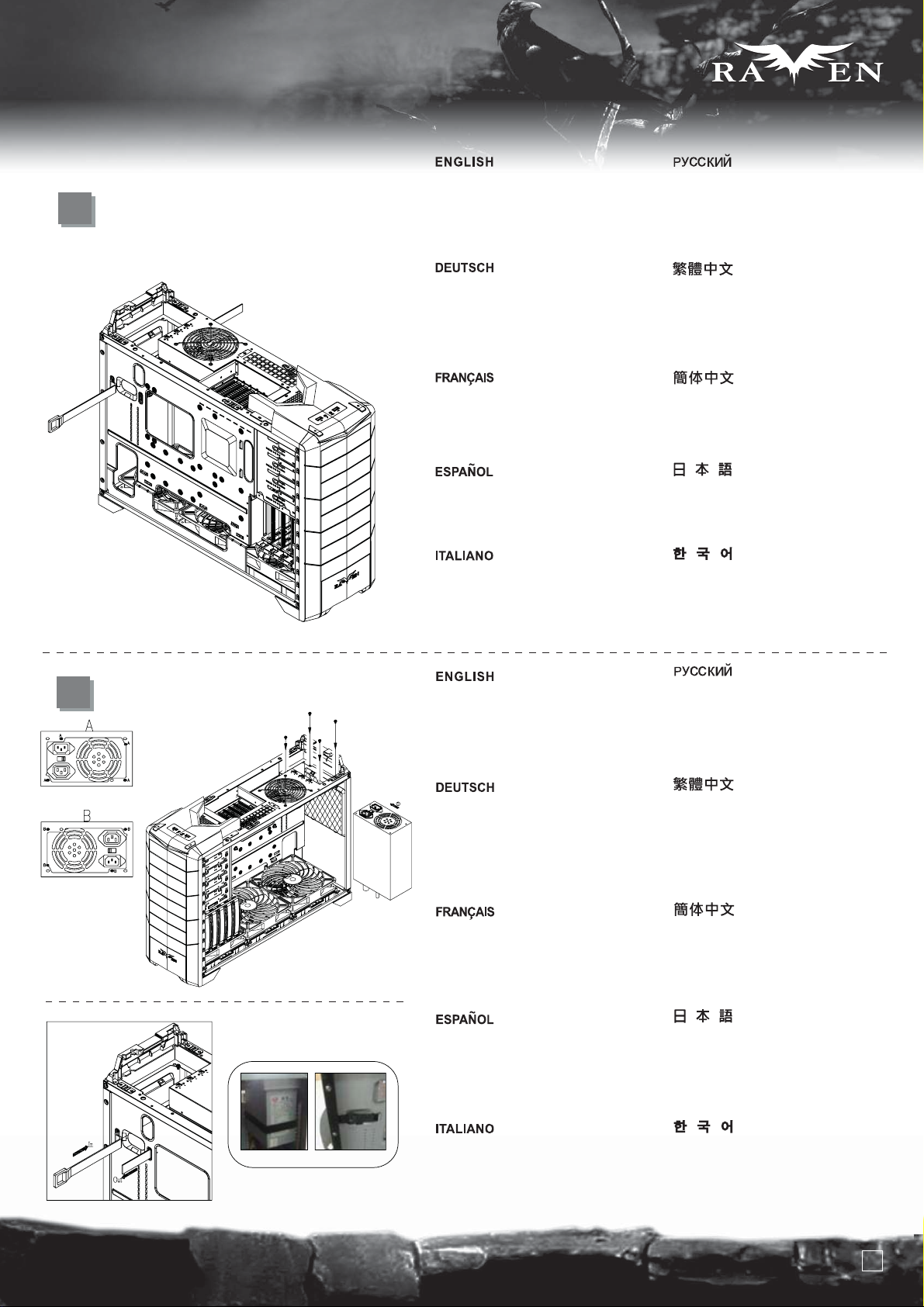
3
Take the included PSU strap from
the accessory box and route it
through the motherboard tray holes
as indicated in the illustration
SERIES
SERIES
Возьмите прилагаемый ремень-фиксатор
блока питания из коробки с аксессуарами
и пропустите его через отверстия в
лотке для материнской платы, как указано
в руководстве.
4
Nehmen Sie das mitgelieferte
Netzteilkabel aus der Zubehörkiste
und führen Sie es wie in der Abbildung
gezeigt durch die Löcher des
Motherboard-Einschubs.
Prenez l'attache pour l'alimentation
incluse dans la boîte d'accessoire et
faites la passer à travers les trous du
support de carte mère comme illustré
Coja la tira para la FA de la caja de
accesorios y pásela por los agujeros
de la placa base como indica la ilustración.
Prelevare la fascetta per l’alimentatore
dal box degli accessori e passarla
attraverso i fori del supporto della
scheda madre come mostrato in figura
Install PSU into the case as shown
(two orientations are available in A or B),
use screw C to secure the PSU
Route the PSU strap around the PSU and
through to the corresponding hole on the
motherboard tray to tighten the PSU
從零件包內取出魔鬼氈,
請依圖示穿過主機板上的過線孔.
从零件包内取出魔鬼毡,
请依图示穿过主机板上的过线孔。
付属のPSUストラップをアクセサリーボッ
クスから取り出し、図のように、マザ
ーボードトレーの穴に通します。
동봉된 PSU 스트랩을 액세사리
박스에서 준비해, 그림에 나타난
메인보드 트레이의 구멍으로 통과
시킵니다.
Вставьте блок питания в корпус, как показано на
рисунке (возможны два способа расположения: A или B),
закрепите блок питания с помощью шурупа С.
Закрепите блок питания, обернув вокруг него
ремень-фиксатор и продев его в соответствующие
отверстия лотка материнской платы.
Installieren Sie das Netzteil wie dargestellt im
Gehäuse (in A oder B sind zwei Ausrichtungen
verfügbar), befestigen Sie das Netzteil mit
Schraube C.
Führen Sie zur Befestigung des Netzteils das
Netzteilband um das Netzteil herum und durch
das entsprechende Loch am Motherboard-Einschub.
Installez l'alimentation dans le boîtier comme
montré (deux orientations sont possibles en
A ou B), utilisez la vis C pour fixer l'alimentation
Faites passer l'attache autour de l'alimentation
et à travers les trous correspondants sur le
support de la carte mère pour serrer l'alimentation
Instale la FA en la carcasa como se muestra
(en A ó B se permiten dos orientaciones), use el
tornillo C para fijar la FA.
Pase la tira de la FA alrededor de la FA y por el
agujero correspondiente en la bandeja de la placa
base para asegurar la FA.
Installare l’alimentatore nel case come mostra
C
l’immagine, (è possibile orientarlo nei modi
A o B), usare le viti C per fissarlo
Passare la fascetta intorno alla PSU nel foro
corrispondente sul supporto scheda madre per
assicurare l’alimentatore al case
請依圖示將電源放入機殼內,
並調整位置(電源支援正反安裝,如圖A,圖B),
用SCREW C 螺絲鎖固
將魔鬼氈由另一個洞穿回主機板底板背面,
並束緊
请依图示将电源放入机箱内,并调整位置
(电源支援正反安装,如图A,图B),
用SCREW C螺丝锁固。
将魔鬼毡由另一个洞穿回主机板底背板面,并束紧。
図のように、ケースの中にPSUをインストールし
(AまたはBの2方向が可能)、ネジCでPSUを固定します。
PSUストラップをPSUのまわりに通し、マザーボ
ードトレーの上の対応する穴に通してPSUを固
定します。
PSU를 그림에서와 같이(두가지 방향 A B로 설치 가능합니다 )
설치하고, 나사 C로 PSU를 고정합니다.
PSU 스트랩을 PSU 주변과 메인보드 트레이에
있는 적절한 구멍으로 통과 시켜 PSU을 단단히
고정시킵니다.
6
Page 8
SERIES
SERIES
lnstallation Guide
5
Take the included PSU holder from
the accessory box and secure it with
screw C to the case
Возьмите прилагаемый держатель
блока питания из коробки с аксессуарами и
прикрепите его к корпусу шурупом С.
6
Nehmen Sie die mitgelieferte
Netzteilhalterung aus der Zubehörkiste,
sichern Sie diese mit Schraube C am
Gehäuse.
Prenez la fixation d'alimentation
incluse dans la boîte d'accessoires
et fixez-la avec des vis C au boîtier
Coja el soporte para la FA incluido de
la caja de accesorios y fíjela a la
carcasa con el tornillo C.
Prendere il fermo per l’alimentatore
dalla scatola degli accessori e fissarlo
al case con le viti C
Use a screw driver to push out the
front 5.25” drive bay covers through
oval holes located on the left front
side as shown
從零件盒內取出電源支撐架,
再用SCREW C 鎖固於機身.
从零件盒内取出电源支撑架,
再用SCREW C锁固于机身。
付属のPSUホルダーをアクセサリーボックス
から取り出し、ネジCでケースに固定します。
동봉된 PSU 홀더를 악세사리 박스에서
꺼내, 나사 C로 케이스에 고정시킵니다.
С помощью отвертки протолкните
передние крышки отсека для
5,25-дюймового дисковода через
овальные отверстия левой части
передней панели, как показано на рисунке.
Drücken Sie die Abdeckungen der
vorderen 5,25-Zoll-Laufwerkseinschübe
wie in der Abbildung gezeigt mit Hilfe
eines Schraubendrehers durch die
ovalen Löcher an der linken vorderen
Seite heraus.
Utilisez un tournevis pour faire sortir les
caches des baies 5.25” à travers les
trous ovales situées sur le côté avant
gauche comme montré
Use un destornillador para sacar las
tapas de las bahías de dispositivo de
5,25” empujando a través de los
agujeros ovalados situados en la parte
frontal izquierda como se muestra.
Usare un cacciavite, facendo leva nei
fori ovali situati alla sinistra dei cover,
per rimuovere i cover dei bay da 5,25”
7
用手動起子,通過機殼左邊前板上的橢圓孔,
向前頂,取出CD COVER.
用手动起子,通过机箱左边前板上的椭圆孔,
向前顶,取出CD COVER。
図のように、正面左に位置する楕円形の
穴を通して、フロントの5.25インチドライブ
ベイカバーをドライバーで取り出します。
스크류 드라이버를 이용해, 전면 5.25”
드라이브 베이 커버를 그링에서와 같이
전면 왼쪽의 타원 구멍으로 밀어 냅니다.
Page 9
lnstallation Guide
SERIES
SERIES
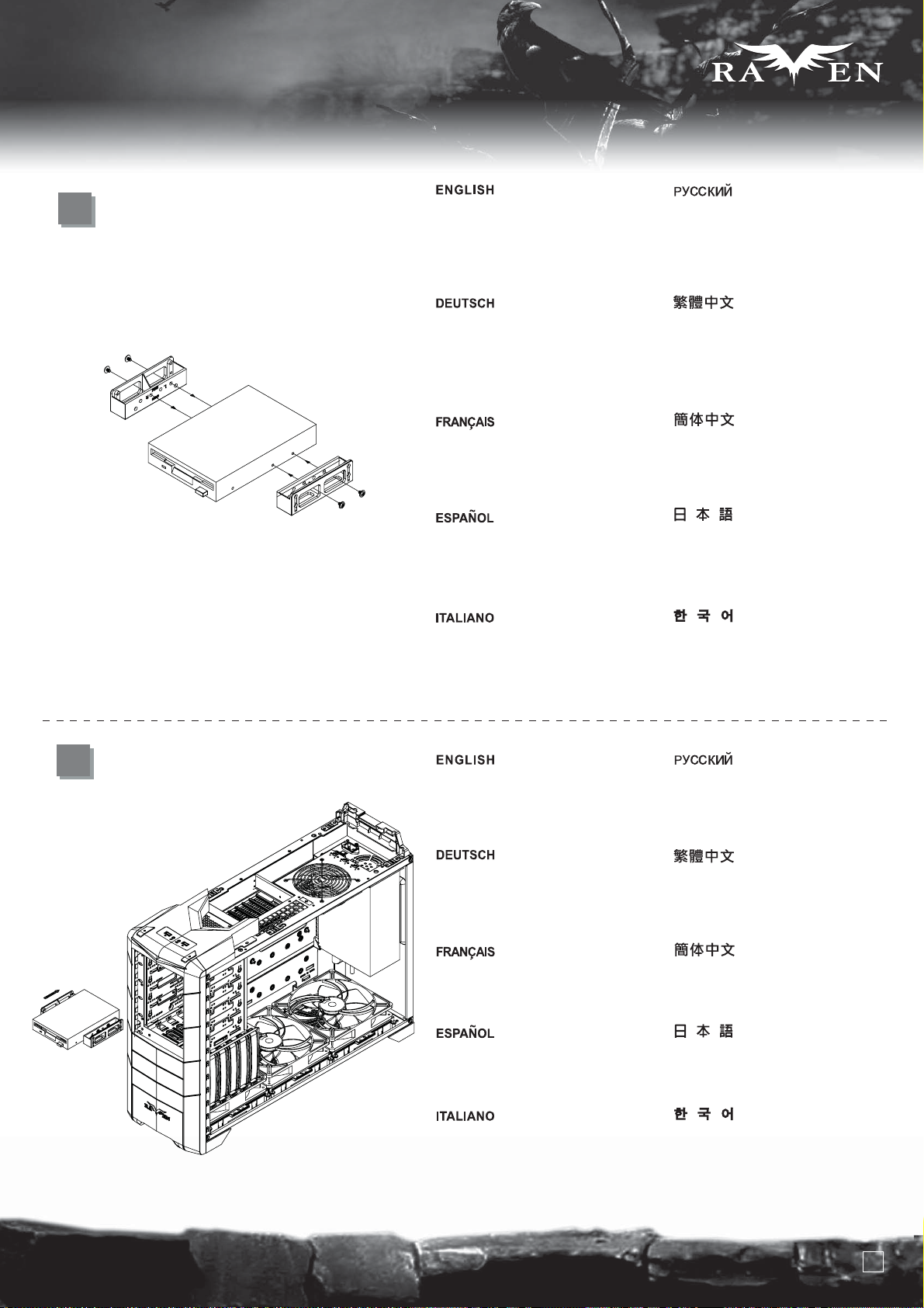
7
Take a pair of 5.25” to 3.5” converter bay
adapters from the accessory box and
attached it to any external 3.5” drive bay
device of your choice using screw A
Nehmen Sie ein Paar der
5,25-Zoll-auf-3,5-Zoll-Konvertereinschubadapter
aus der Zubehörkiste; befestigen Sie
diese mit Schraube A an einem
beliebigen externen 3,5-Zoll-Laufwerk.
Prenez une paire de convertisseurs
de baies 5.25” vers 3.5” de la boîte
d'accessoires et fixez-y n'importe quel
appareil 3.5” en utilisant des vis A
Coja un par de conversores de 5,25”
a 3,25” de la caja de accesorios y
fíjelos a cualquier dispositivo externo
de 3,25” de su elección usando el tornillo A
Prendere una coppia di adattatori
da 5,25” a 3,5” dalla scatola degli
accessori e fissarli ad una periferica
da 3,5” a vostra scelta, utilizzando le
viti A
Возьмите пару адаптеров конвертеров
отсеков для 5,25- и 3,5-дюймовых
устройств из коробки с аксессуарами и
прикрепите их к любому внешнему
3,5-дюймовому отсеку с помощью шурупа A.
從零件包內取出5.25吋轉3.5吋的轉換架,
用Screw A將其鎖固於FDD上
从零件包内取出5.25吋转3.5吋的转换架,
用Screw A将其锁固于FDD上
アクセサリーボックスからの5.25インチ-3.5
インチ変換アダプタ一式を取り出し、お好き
な外側3.5インチドライブベイデバイスにネジAで
固定します。
5.25” – 3.5” 전환 베이 어댑터를
악세사리 박스에서 꺼내, 원하는 3.5”
드라이브베이에 나사 A를 이용해 고정합니다.
8
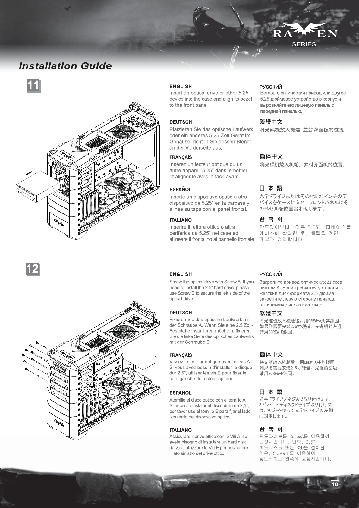
Insert the assembled external 3.5”
drive bay device into the case and
align with 5.25” drive bay mounting
holes
Platzieren Sie das montierte externe
3,5-Zoll-Laufwerk im Gehäuse, richten
Sie es an den Montagelöchern des
5,25-Zoll-Einschubs aus.
Insérez le casier assemblé avec
l'appareil dans le boîtier et alignez le
avec les trous de montage de la baie 5.25”
Inserte el dispositivo externo de 3,25”
montado en la carcasa y alinéelo con los
agujeros de montaje del dispositivo de 5,25”.
Inserire quindi il complesso assemblato
nel case ed allinearlo con i fori di
montaggio del bay da 5,25”
Вставьте собранный внешний
3,5-дюймовый отсек в корпус и
выровняйте его по крепежными
отверстиям 5,25-дюймового отсека.
將FDD放入機殼內,並對準機殼上的鎖固孔.
将FDD放入机箱内,并对准机箱上的锁固孔。
組み立てられた外側3.5インチドライブベイデ
バイスをケースに入れ、5.25インチドライブベ
イ取り付け穴に合わせます。
조립된 외부 3.5” 드라이브 베이를
케이스에 넣고, 5.25” 드라이브
베이와 정렬시킵니다.
8
Page 10
SERIES
SERIES
lnstallation Guide
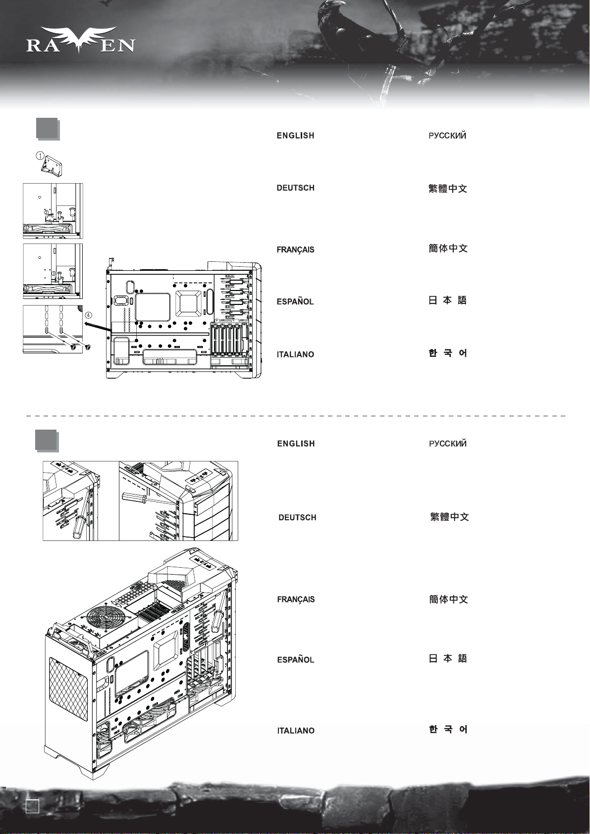
9
10
Use Screw C to secure it to the case
Befestigen Sie es mit Schraube
C am Gehäuse.
Utilisez une vis C pour le fixer au
boîtier
Use el tornillo C para fijarlo a la
carcasa.
Usare le viti C per assicurarlo al case
Прикрепите отсек к корпусу с
помощью шурупа C.
用SCREW C 將其鎖固於機殼.
用SCREW C将其锁固于机箱。
それをネジCでケースに固定します。
나사 C를 이용해 케이스에 고정시킵니다.
Install the 5.25” to 3.5” drive bay
cover to the front panel
Installieren Sie die Abdeckung des
5,25-Zoll-auf-3,5-Zoll-Festplatteneinschubs
an der Vorderseite.
Installez le cache de baie 5.25”
vers 3.5” sur le panneau frontal
Instale la cubierta de bahía de
dispositivo de 5,25” a 3,25” en
el panel frontal.
Installare il cover da 5,25” a 3,5” sul
pannello frontale
Установите на переднюю панель
крышку 5,25- и 3,5-дюймовых отсеков.
將FDD轉換檔板裝上面板
将FDD转换挡板装上面板
フロントパネルに5.25インチ-3.5インチドラ
イブベイのカバーを取り付けます。
5.25” – 3.5” 드라이브 베이 커버를
전면 패널에 설치 합니다.
9
Page 11
Page 12
SERIES
SERIES
lnstallation Guide
13
14
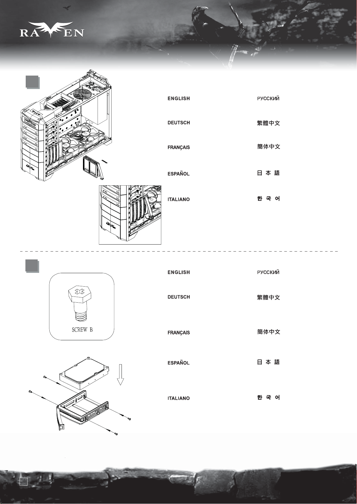
Remove the hard drive tray as shown
Nehmen Sie den Festplatteneinschub
wie abgebildet heraus
Retirez le support à disques durs
comme montré
Quite la bandeja para discos duros
como se muestra
Rimuovere il cestello dell’hard disk
come mostrato
Выньте корзину для жесткого диска,
как показано на рисунке.
請依圖示將硬碟托盤取出。
请依图标将硬盘托盘取出。
図のようにハードディスクドライブト
レイを取り外します。
하드 드라이브 트레이를 그림과 같이
제거합니다.
Insert hard drive into the hard drive tray
and then use screw B to secure it
Setzen Sie die Festplatte in den
Festplatteneinschub ein, fixieren
Sie die Festplatte mit der
Schraube B.
Insérez un disque dur dans le
support puis utilisez des vis de
type B pour le fixer
Inserte el disco duro en la bandeja
paradiscos duros y luego use el
tornillo Bpara fijarlo
Inserire l’hard disk nel cestello quindi
usare le viti B per serrarlo
Вставьте жесткий диск в корзину и
закрепите его шурупом В.
將硬碟放入托盤內,並在兩側用螺絲
(SCREW B)將其鎖固。
将硬盘放入托盘内,并在两侧用螺丝
(SCREW B)将其锁固。
ハードドライブをハードドライブトレイに
入れてから、ネジBで固定します。
하드 드라이브를 하드 드라이브
트레이에 삽입한 후, 나사 B를
이용해 고정시킵니다.
11
Page 13

lnstallation Guide
15
SERIES
SERIES
Insert the completed hard drive tray back into the case (additional CP05 adapters can be purchased separately to make all
SATA hard drives hot-swappable)
Setzen Sie den Einschub mit Festplatte wieder in das Gehäuse ein. (Mit separat erhältlichen CP05-Adaptern können Sie sämtliche
SATA-Festplatten für Hot-Swapping vorbereiten.)
Remettez le support rempli avec ses disques durs dans le boîtier (des adaptateurs CP05 peuvent être achetés séparément pour
ajouter la fonction "hot-swap" à tous vos disques SATA)
Inserte la bandeja para discos duros completada de nuevo en la carcasa (se pueden comprar por separado adaptadores adicionales
CP05 para hacer que todos los discos duros SATA sean cambiables en caliente)
Inserire il complesso montato nel case (Possono essere acquistati separatamente adattatori CP05 addizionali, al fine di rendere tutti
gli hard disk hot-swappable)
Вставьте корзину с жестким диском в корпус (приобретите дополнительные адаптеры CP05, чтобы получить возможность
горячего подключения жестких дисков SATA).
將硬碟拖盤放回機殼內(可選用CP05轉接線模組,可升級成熱插拔SATA硬碟)。
将硬盘拖盘放回机壳内(可选用CP05转接线模块,可升级成热插拔SATA硬盘)。
組まれたハードディスクドライブトレイをケースに戻します (全てのドライブをホットスワップ対応にするには追加のCP05アダプタを
購入できます)。
고정시킨 하드 드라이브 트레이를 케이스에 재 삽입합니다. ( 추가적로 CP05 어댑터를 구입해 장착하면, 모든 SATA 하드
드라이브의 핫스왑이 가능합니다. )
12
Page 14

SERIES
SERIES
lnstallation Guide
16
17
Place the 2.5” hard drive into the 2.5”
drive bracket as shown
Platzieren Sie die 2,5-Zoll-Festplatte
wie gezeigt in der
2,5-Zoll-Festplattenhalterung.
Mettez le disque dur 2.5” dans le
casier dédié comme montré
Coloque el disco duro de 2,5” en el
bracket para discos duros de 2,5”
como se muestra.
Porre il disco da 2,5” nell’apposita
staffa come mostrato
Поместите 2,5-дюймовый жесткий
диск в кронштейн для 2,5-дюймового
диска, как показано на рисунке.
請將2.5吋硬碟依圖示放入2.5吋硬碟架
请将2.5吋硬盘依图示放入2.5吋硬盘架
図のように、2.5インチハードドライブを2.5
インチドライブブラケットに入れます。
2.5” 하드 드라이브를 그림에서와
같이 2.5” 드라이브 브라켓에 놓습니다.
Use screw A to secure the 2.5” hard
drive to the bracket
Sichern Sie die 2,5-Zoll-Festplatte
mit Schraube A an der Halterung.
Utilisez des vis A pour fixer le
disque dur 2.5” au casier
Use el tornillo A para fijar el disco
duro de 2,5” al bracket.
Utilizzare le viti A per assicurare il
disco alla staffa
С помощью шурупа A прикрепите
2,5-дюймовый жесткий диск к
кронштейну.
請依圖示用SCREW-A,將2.5吋
硬碟鎖固於2.5吋硬碟架
请依图示用SCREW-A,将2.5吋
硬盘锁固于2.5吋硬盘架。
2.5インチハードドライブをネジAでブラ
ケットに固定します。
나사 A를 이용해 2.5” 하드
드라이브를 브라켓에 고정시킵니다.
13
Page 15

lnstallation Guide
SERIES
SERIES
18
Use screw A to secure the 2.5”
drive bracket to the case
Sichern Sie die
2,5-Zoll-Festplattenhalterung mit
Schraube A am Gehäuse.
Utilisez des vis A pour fixer le
casier au boîtier
Use el tornillo A para fijar el bracket
para dispositivos de 2,5” a la carcasa.
Utilizzare le viti A per assicurare la
staffa al case
С помощью шурупа A прикрепите
кронштейн для 2,5-дюймового
диска к корпусу.
請依圖示用SCREW-A,
將2.5吋硬碟架鎖固於機身.
请依图示用SCREW-A,
将2.5吋硬盘架固于机身。
2.5インチハードドライブブラケットをネジAで
ケースに固定します。
나사 A를 2.5” 드라이브 브라켓을
케이스에 고정시킵니다.
19
Insert all standoffs to corresponding holes on
the motherboard tray as required by your
motherboard, then place the motherboard on
the standoffs and secure it with screw C
Stecken Sie die Abstandshalter gemäß Ihres
Motherboards in die entsprechenden Löcher
des Motherboard-Einschubs; platzieren Sie das
Motherboard dann auf den Abstandshaltern
und sichern Sie es mit Schraube C.
Insérez tous les plots nécessaire au trous de
montage de votre carte mère, puis placez-y
votre carte mère et fixez-la avec des vis C
Inserte todos los soportes en los agujeros
correspondientes de la bandeja de la placa
base según precise su placa base, luego sitúe
la placa base en los soportes y fíjela con el tornillo C.
Inserire, a seconda del tipo di mainboard,
gli standoff necessari nella sede della scheda
madre quindi appoggiarla sui supporti ed
assicurarla agli stessi per mezzo delle viti C
Вставьте все опоры в соответствующие
отверстия лотка для материнской платы,
затем поместите материнскую плату на
опоры и закрепите шурупом C.
請依需求將SCREW D 的主機板螺柱鎖固於機殼,
再將主機板裝入機殼,用SCREW C 螺絲將其鎖固.
请依需求用SCREW D的主机板螺柱锁固于机箱,
再将主机板装入机箱,并用SCREW C 螺丝将其锁固。
マザーボードによって必要とされるスペーサーを、
マザーボードトレーの上に対応する穴に入れ、
マザーボードを水平に置いて、ネジCで固定します。
메인보드에 맞추어 메인보드 트레이에 지지
나사를 삽입한 후, 메인보드를 올려 놓고,
나사 C로 고정시킵니다.
14
Page 16

SERIES
SERIES
lnstallation Guide
20
Remove the expansion slot covers as
required then insert expansion card
into the case. Secure with screws
used to secure the expansion slots
Entfernen Sie die Abdeckungen der
benötigten Erweiterungssteckplätze;
stecken Sie die Erweiterungskarte(n)
in das Gehäuse. Sichern Sie diese mit
den Schrauben, mit denen die
Erweiterungssteckplätze gesichert waren.
Retirez les caches des emplacements
d'extension selon vos besoins. Fixez
les cartes avec des vis
Quite las cubiertas de las ranuras de
expansión que sean necesarias y luego
inserte la tarjeta de expansión en la
carcasa. Fíjela con los tornillos que se
usan para fijar las ranuras de expansión.
Rimuovere i cover degli slot di
espansione, quindi inserire la scheda
di espansione. Assicurarla utilizzando
la vite rimossa in precedenza
Снимите крышки слотов расширения,
затем установите карту расширения
в корпус. Закрепите шурупами, которые
использовались для защиты слотов расширения.
先取下擴充槽上的檔板,再將擴充卡裝入,
用內附螺絲鎖固.
先取下扩充槽上的挡板,再将扩充卡装入,
并用内付螺丝锁固。
必要に応じて拡張スロットカバーを取り外し、
拡張カードをケースに入れます。拡張
スロットを固定していたネジで固定します。
필요한 만큼 활장슬롯 커버를
제거한 후, 필요한 확장카드를 케이스에
삽입한 후, 나사로 고정시킵니다.
21
After all wires and cables are connected
and routed, place the side panels back
onto the case and secure with thumb
screws removed from step 2
Nachdem alle Drähte und Kabel verlegt
und angeschlossen sind, befestigen
Sie die seitlichen Blenden wieder am
Gehäuse; sichern Sie die in Schritt 2
entfernten Flügelschrauben.
Après avoir brancher tous les câbles,
remettez les panneaux latéraux sur le
boîtier et fixez-les avec des vis à main
retiré lors de l'étape 2
Después de que todos los cables
estén conectados y enrutados, vuelva
a colocar los paneles laterales en la
carcasa y fíjelas con los tornillos
manuales que se quitaron en el paso 2.
Dopo che tutte le connessioni sono
state stabilite, riposizionare i pannelli
laterali ed assicurarli alla struttura
portante per mezzo delle viti rimosse
al punto 2
После подключения всех проводов и кабелей
верните на место боковые панели корпуса и
закрепите винтами с рифленой головкой,
открученными на этапе 2.
把左右側板裝回機殼,
並用6#32手扭螺絲鎖固.
把左右側板装回机箱,
并用6#32手扭螺丝锁固。
すべてのリード線とケーブルが接続され、
取り回された後、ケースにサイドパネルを
戻し、ステップ2で外したつまみネジで
固定します。
모든 선과 케이블의 연결을 확인한
후 사이드 패널을 케이스에 재 설치한
후, 손나사로 고정시킵니다.
15
Page 17

lnstallation Guide
SERIES
SERIES
22
Place the top cover back onto the
case to complete installation
Platzieren Sie zum Abschluss der
Installation die obere Abdeckung
wieder am Gehäuse.
Remettez le cache supérieur sur le
boîtier pour terminer l'installation
Vuelva a colocar la cubierta superior
en la carcasa para completar la
instalación.
Riposizionare il cover superiore per
completare l’installazione
Установите на место верхнюю крышку
корпуса. Сборка завершена.
將上蓋裝回機殼,完成組裝.
将上盖装回机箱,完成组装。
ケースに上部カバーを戻すと、インストール
完了です。
상부 커버를 케이스에 재 설치한
후 설치를 마칩니다.
16
Page 18

SERIES
SERIES
Connector definition
(1) Front panel connector installation
Power switch and reset switch installation guide:
Please refer to the motherboard manuals for the motherboard’s “Front Panel Connector” or “System Panel Connector” pin definition. Power
switch and reset switch have no polarity, so they can be connected in any orientation.
Bitte suchen Sie in der Motherboard-Dokumentation nach der Pinbelegung der Anschlüsse des Frontbedienfeldes („Front Panel Connectors“
oder „ System Panel Connectors“). Ein-/Austaste und Rücksetztaste benötigen keine bestimmte Polarität, können daher beliebig (ohne auf +
und - zu achten) angeschlossen werden.
Veuillez-vous référer au manuel de votre carte mère pour la description des broches "des connecteurs du panneau frontal" et des broches
"des connecteurs du panneau système". Les interrupteurs d'allumage et de réinitialisation ne possède pas de polarité, donc ils peuvent être
branché dans les deux sens.
Por favor, consulte en los manuales de la placa base la configuración de pines del “Conector de panel frontal” ó “Conector de panel de sistema”
de su placa base. Los interruptores de encendido y reseteo no tienen polaridad, luego se pueden conectar con cualquier orientación.
Fare riferimento al manuale della scheda madre nella sezione “Connettori del pannello frontale” o “Connettori del pannello di sistema”. Power
switch e reset switch non hanno polarità, posso essere pertanto connessi con qualsiasi orientamento.
Описание контактов разъемов приведены в разделах “Разъемы передней панели” или “Разъемы системной панели” руководства
пользователя материнской платы. Выключатель питания и кнопка перезагрузки не имеют полярности, поэтому их можно подключать
в любой ориентации.
マザーボードの「フロントパネルコネクタ」または「システムパネルコネクタ」のピン配列についてはマザーボードマニュアルを参照してください。電源スイ
ッチとリセットスイッチに極性はないので、いずれの方向でも接続できま。
메인보드 매뉴얼의 전면패널 커넥터 혹은 시스템패널 커넥터 핀을 참조하기 바랍니다. 파워 스위치와 리셋 스위치는 극성이 없어 어떤
방향으로 설치해도 무방합니다.
請參考主機說明書的Front Panel Connectors安裝Pin Define,將Connector插上;Power Switch 與Reset Switch並無正負極性之分,
反插正插都不影響功能性。
请参考主机说明书的Front Panel Connectors 安装Pin Define,将Connector插上;Power Switch与Reset Switch并无正负极性之分,
反插正插都不影响功能性。
17
Page 19

SERIES
SERIES
LED connector installation guide:
Please refer to the motherboard manuals for the motherboard’s “Front Panel Connector” or “System Panel Connector” pin definition.;the white
wires are negative while other colors are positive wires. The Power LED wires are separate pins for compatibility with different motherboard pin
definition so please make sure they are connected in the right polarity by referring to your motherboard manual.
LED-Verbinder installieren: Bitte suchen Sie in der Motherboard-Dokumentation nach der Pinbelegung der Anschlüsse des Frontbedienfeldes
(„Front Panel Connectors“ oder „System Panel Connectors“). Die weißen Adern sind negativ (-), die farbigen Adern positiv (+).Die Kabel für die
Betriebsanzeige-LED sind zur Kompatibilität mit unterschiedlichsten Motherboards einzeln, nicht als kompletter Stecker ausgeführt. Achten Sie
hier bitte auf die richtige Polarität, lesen Sie in der Dokumentation Ihres Motherboards nach.
Veuillez-vous référer au manuel de votre carte mère pour la description des broches "des connecteurs du panneau frontal" et des broches "des
connecteurs du panneau système". Les câbles colorés en blanc sont négatifs alors que ceux d'une autre couleur sont positifs.Les câbles de la
LED Power sont séparés afin d'être compatible avec différentes cartes mères, donc vérifiez bien qu'ils sont branchés avec la bonne polarité en
vous référant au manuel de votre carte mère.
Por favor, consulte en los manuales de la placa base la configuración de pines del “Conector de panel frontal” ó “Conector de panel de sistema”
de su placa base. Los cables de color blanco son negativos mientras que los de color son positivos. Los cables LED de potencia tienen pines
separados para compatibilidad con diferentes definiciones de pines de la placa base luego por favor, asegúrese de que están conectados en la
polaridad correcta consultando el manual de su placa base.
Fare riferimento al manuale della scheda madre nella sezione “Connettori del pannello frontale” o “Connettori del pannello di sistema”. I cavi
di colore bianco sono il polo negativo, mentre quelli di colore diverso il positivo.Guida all’installazione del Power Led serie RV/KLConnettere
direttamente il connettore ad un molex dell’alimentatore
Описание контактов разъемов приведены в разделах “Разъемы передней панели” или “Разъемы системной панели” руководства
пользователя материнской платы. Белые провода - отрицательной полярности, цветные провода - положительной полярности.
Провода светодиодного индикатора питания имеют отдельные контакты для совместимости
материнских плат, поэтому обратитесь к руководству пользователя материнской платы и убедитесь, что полярность соблюдена.
LEDコネクタのインストールガイド:
マザーボードの「フロントパネルコネクタ」または「システムパネルコネクタ」ピン配列についてはマザーボードマニュアルを参照してください。白色のリード
線はマイナスで、色の着いたリード線がプラスです。電源LEDリード線は種々のマザーボードピン定義と互換性を持たせるため分離されたピンとなってい
るので、ご使用のマザーボードマニュアルを参照して、 適切な極性に接続されるようお確かめください。
с различными типами контактов
메인보드 매뉴얼의 전면패널 커넥터 혹은 시스템패널 커넥터 핀을 참조하기 바랍니다. 하얀선의 경우 음극이며, 다른 색의 경우
양극입니다. 파워 LED 선은 분리되어 다양한 메인보드에서 동작할 수 있도록 되어 있습니다. 그러므로 메인보드 매뉴얼을 참조하여
올바를 극성을 주의해 선택하시기 바랍니다.
請參考說明書的Front Panel Connectors安裝Pin Define,將Connector插上;白色線的部分為負極,彩色線的部分是正極。Power LED
為了適應各主機板的不同,特別設計為散Pin樣式,請安心使用。
请参考说明书的Front Panel Connectors安装Pin Define,将Connector插上;白色线的部份为负极,彩色线的部份为正极。 Power LED
为了适应主机板的不同,特别设计为散Pin样式,请安心使用。
18
Page 20

SERIES
SERIES
Power LED installation guide:
Please connect this peripheral connector from the case to your power supply.
Bitte verbinden Sie diese Peripherieanschlüsse des Gehäuses mit Ihrem Netzteil.
Veuillez brancher les connecteurs de ces périphériques du boîtier au câble de votre alimentation.
Enchufe el conector de este periférico desde la carcasa hasta su fuente de alimentación.
Connettere direttamente il connettore ad un molex dell’alimentatore
Подсоедините этот периферийный коннектор от корпуса к блоку питания.
ケースから電源まで、この周辺装置のコネクタを接続します。
이 커넥터는 퍼워 서플라이의 4핀 IDE 커넥터에 설치 합니다.
請接此接頭連接上電源供應器的4 pin peripheral power cable,點亮LED。
请将此接头连接上电源供应器的4 pin peripheral power cable,点亮LED
19
Page 21

SERIES
SERIES
Front I/O connector guide
Below are the front I/O connectors pin definition, please also check your motherboard manual to cross reference with motherboard’s
front I/O pin headers. SilverStone’s I/O connectors are in block type to simplify installation.
Nachstehend finden Sie die Pinbelegung der vorderen E/A-Anschlüsse; bitte gleichen Sie zudem das Handbuch Ihres Motherboards mit
den vorderen E/A-Pinzuweisungen ab. SilverStones E/A-Anschlüsse befinden sich zur Vereinfachung der Installation in Blockart.
Au dessous de la description des broches des ports d'E/S, veuillez aussi vérifier sur le manuel de votre carte mère de manière croisée
que les broches sont correctement placées. Les connecteurs d'E/S de SilverStone sont en bloc pour en simplifier leur installation.
A continuación tiene la definición de pines de los conectores frontales de E/S, también debe consultar el manual de su placa base para c
omprobar la referencia de los pines para E/S frontales. Los conectores de E/S de SilverStone son de bloque para simplificar la instalación.
Di seguito lo schema delle connessioni I/O frontali, confrontare lo schema con quanto riportato sul manuale della scheda madre per
effettuare una controllo incrociato. I connettori I/O Silverstone, per semplificare l’installazione, sono del tipo “a blocco”.
Ниже приведено описание контактов передних разъемов ввода/вывода. Обратитесь также к руководству пользователя материнской
платы за описанием передних разъемов ввода/вывода типа "пин-хедер". Разъемы ввода/вывода "SilverStone" - блочного типа, что
облегчает сборку.
以下はフロントI/Oコネクタピン配列ですが、お持ちのマザーボードのフロントI/Oピンヘッダは、マザーボードマニュアルをご参照ください。
シルバーストーンのI/Oコネクタは、インストールの容易なブロックタイプになっています。
아래는 전면 I/O 커넥터의 핀 설정이며, 메인보드 매뉴얼을 참조해 메인보드의 전면 I/O 핀 헤더와 맞추어 설치합니다.
Silverstone의 I/O 커낵터는 블록 타이브로 구성되어 설치를 간편화 했습니다.
下表為Front I/O Connectors的Pin Define,請參閱主機板說明書的各Front I/O Connectors Pin Define一一核對。
RV02-E的Front I/O Connectors完全採用集合Pin方式以簡化安裝。
下表为Front I/O Connectors的Pin Define,请参阅主机板说明书的各Front I/O Connectors Pin Define一一核对。
RV02-E的Front I/O Connectors完全采用集合Pin方式以简化安装。
20
Page 22

SERIES
SERIES
Liquid cooling installation guide
For liquid cooling, the maximum thickness allowed for radiator is 30mm when 10.5” expansion cards are installed and 60mm
when 9” cards are installed.
1
Please remove 180mm fan filters as
shown then remove the four 3*8 screws
holding the 180mm fan bracket
Bitte entfernen Sie wie dargestellt die
Filter des 180 mm-Lüfter, entfernen
Sie dann die vier 3*8-Schrauben, über
die die Halterung des 180 mm-Lüfters
befestigt ist.
Veuillez retirer les filtres du ventilateur
de 180mm comme montré puis retirer
les quatre vis 3*8 tenant le casier du
ventilateur de 180mm
Por favor, retire los filtros de los ventiladores
de 180mm como se muestra y luego quite
los cuatro tornillos 3*8 que sujetan el bracket
del ventilador de 180mm
Rimuovere il filtro della ventola da
180mm come mostrato quindi
rimuovere le 4 viti 3*8 che trattengono
il support della ventola.
Снимите фильтры 180-мм вентилятора,
как показано на рисунке, затем открутите
шесть шурупов 3*8, удерживающих
кронштейн вентилятора.
請依圖示取出180風扇濾網,鬆開
鎖固風扇架的4顆3*8的螺絲。
请依图示取出180风扇滤网,松开
锁固风扇架的4颗3*8的螺丝。
図のように180mmファンフィルタを外
し、180mmファンブラケットを固定し
ている3*8ネジ4本を外します。
그림에서와 같이 180mm 팬필터를 제거
한 , 180mm 팬 브라켓을 고정하고 있
는 4개의 3 x8 나사를 제거합니다.
2
Remove the four M2*3 screws holding the
fan switch for the 180mm fans from the top
panel (indicated by labels “front,” “middle,
” and “rear”)
Entfernen Sie die vier M2*3-Schrauben
vom oberen Paneel, die den
Lüftermotorschalter der 180 mm-Lüfter
halten (durch Etiketten gekennzeichnet:
„vorne“, „Mitte“ und „hinten“).
Retirer les quatre vis M2*3 tenant
l'interrupteur du ventilateur pour les
ventilateurs de 180mm par le panneau
supérieur fans (indiqué par les
étiquettes “front,” “middle,” et “rear”)
Quite los cuatro tornillos M2*3 que
sujetan el interruptor de ventilador para
los ventiladores de 180mm del panel
superior (indicado por las etiquetas
“frontal”, “medio” y “posterior”)
Rimuovere le 4 viti M2*3 dell’interruttore
delle ventole da 180mm dal pannello
superiore (indicato dalle etichette
“front,” “middle,” e “rear”)
Открутите шесть шурупов M2*3 на верхней
панели, удерживающих переключатели
режимов 180-мм вентиляторов (они
обозначены табличками “front” ("передний")
“middle” ("средний") и “rear” ("задний")).
取下鎖固180風扇開關的4顆M2*3的螺絲
(請依照上板上的"FRONT","MIDDLE",REAR
選擇您所需拆卸的風扇開關)。
取下锁固180风扇开关的4颗M2*3的螺丝
(请依照上板上的"FRONT","MIDDLE",REAR
选择您所需拆卸的风扇开关)。
上部パネルから180mmファンのファン
スイッチ( 「前」、「中」、「後」
と記号で表示)を固定しているM2*3ネ
ジ4本を外します。
상부 패널의 180mm 팬 스위치를 고
정하고 있는 4개의 M2 x 3 나사를
제거합니다. (“front,”“middle,”
“rear” 로 표시되어 있습니다. )
21
Page 23

SERIES
SERIES
3
Remove 180mm fan
bracket from the case.
Entfernen Sie die Halterung des
180 mm-Lüfters vom Gehäuse.
Retirer le casier du ventilateur
de 180mm du boîtier.
Quite el bracket paraventilador de
180mm de la carcasa.
Rimuovere il supporto della
ventola da 180mm dal case.
Выньте из корпуса кронштейн
180-мм вентилятора.
請依圖示抽出180風扇架。
请依图示抽出180风扇架。
ケースから180mmファンブラケットを取り外し。
180mm 팬 브라켓을 케이스로 부터 제거한.
4
Use the included radiator bracket from the
accessories box and secure them onto the
radiator
Verwenden Sie die mitgelieferte
Kühlerhalterung aus der Zubehörkiste;
befestigen Sie diese am Kühler.
Utiliser le casier à radiateur inclus dans
la boîte d'accessoires et fixer les sur le
radiateur
Use el bracket para disipador incluido
en la caja de accesorios y encájelo en
el disipador
Utilizzare le staffe del radiatore a corredo
ed applicarle al radiatore
Выньте кронштейн радиатора из
коробки с аксессуарами и укрепите
его на радиаторе.
從零件包內取出水冷固定架,
用鎖固水泠排的螺絲將其鎖固於水冷排上
从零件包内取出水冷固定架,
用锁固水冷的螺丝將其鎖固於水冷排上。
アクセサリボックスの付属のラジエータブラ
ケットを使用して、ラジエータに固定します。
액세서리상자에 동봉된 라디에이터
브래킷을 라디에이터 위에
고정시키십시오.
22
Page 24

5
SERIES
SERIES
6
Secure the radiator onto the fans as shown
Befestigen Sie den Kühler wie dargestellt
an den Lüftern.
Fixer le radiateur sur les ventilateurs
comme montré
Fije el disipador a los ventiladores como
se muestra
Assicurare quindi il radiator alle ventole
come mostrato
Закрепите радиатор поверх
вентиляторов, как показано на
рисунке.
請依圖示將水冷排鎖固於風扇上
请依图示将水冷排锁固在风扇上。
図のように、ファンにラジエータを固定します。
그림처럼 라디에이터 위에 팬을
고정시키십시오.
23
Install the radiator/fan assembly into the
case and secure with screws
Installieren Sie die Kühler-Lüfter-Montage
im Gehäuse, befestigen Sie diese mit
Schrauben.
Installer le couple radiateur/ventilateur
dans le boîtier et fixer le avec des vis
Instale el conjunto de disipador/ventilador
en la carcasa y fíjelo con los tornillos
Installare il complesso radiator/ventole nel
case e serrare il tutto con le viti
Установите в корпус блок
радиатор/вентиляторы и закрепите
шурупами.
請將鎖固好水冷排的風扇架,
放入機殼,並用螺絲將其鎖固
请将锁固好水冷排的风扇架放入机箱,
并用螺丝将其锁固。
ケースにラジエータ/ファンアセンブリを
取り付け、ねじで固定します。
팬이 조립된 라디에이터를 본체 안에
설치하고 나사로 고정시키십시오.
Page 25

7
SERIES
SERIES
Insert fan filters back into the fan bracket,
please make sure the filters are in the
correct orientation
Stecken Sie die Lüfterfilter wieder in die
Lüfterhalterung; achten Sie auf die
korrekte Ausrichtung der Filter.
Réinsérer les filtres des ventilateurs dans
le casier, veuillez bien vérifier que les
filtres sont mis dans le bon sens
Inserte los filtros para ventilador en el
bracket del ventilador, por favor asegúrese
de que los filtros están correctamente
orientados
Inserire nuovamente il filtro nella staffa,
facendo attenzione al corretto
orientamento
Вставьте фильтры вентилятора
обратно в кронштейн вентилятора.
Убедитесь, что фильтры правильно
ориентированы.
請將180風扇濾網插入風扇架,
注意180風扇濾網插入時的方向性.
请将180风扇滤网插入风扇架,
注意180风扇滤网插入时的方向性。
ファンフィルタをファンブラケットに挿入
します。フィルタの方向が正しいことを
確認してください。
팬 브래킷에 팬 필터를 설치하고,
필터가 정확히 장착 되었는지
확인하십시오.
8
YELLOW (H)
BLACK
RED (L)
Reinstall all fan switches back onto the
top panel, be sure to note the correct
orientation and position of the fan switches
Installieren Sie sämtliche
Lüftermotorschalter wieder am oberen
Paneel; achten Sie auf die korrekte
Ausrichtung und Position der
Lüftermotorschalter.
Réinstaller tous les interrupteurs des
ventilateurs sur le panneau supérieur,
vérifiez bien l'orientation et la position
de chaque interrupteur de ventilateur
Reinstale todos los interruptores de
ventiladores en el panel superior y
asegúrese de que están orientados y
situados de forma correcta
Reinstallare tutti gli interruttori delle ventole
sul pannello frontale, avendo cura di
rispettare le posizioni originarie
Вновь установите на верхнюю панель
все переключатели режимов
вентиляторов. Убедитесь в правильной
ориентации и положении переключателей.
請依照上板上的"H"-"L"及左上角的180風扇
開關接線示意圖,將180風扇開關鎖固於上板.
请依照上板的"H"-"L"及左上角的180风扇
开关接线示意图,将180风扇开关索固于上板。
すべてのファンスイッチを上面パネルに再
び取り付けます。ファンスイッチの方向
と位置が正しいことを確認してください。
상부 위의 모든 팬 스위치들을
역순으로 다시 고정하고, 팬 스위치가
지정된 위치에 정확히 설치되었는지
확인 하십시오.
24
Page 26

SERIES
SERIES
Component size limitations
The RAVEN RV02-E was designed to accommodate oversize components,
but we still recommend to refer to the following dimension guidelines:
Maximum height for CPU cooler is 169mm
Maximum depth for power supply is 230mm
25
Page 27

Graphic card/expansion card length limitation
RV02-E can support 12.2” consumer level graphics cards.
Graphic card length reference:
AMD Radeon HD 5970 – 12.2"
AMD Radeon HD 5870 – 11”
NVIDIA GeForce GTX295/285/275/260 - 10.5"
NVIDIA GeForce 9800GTX/9800GTX+ - 10.5"
AMD Radeon HD 4870X2 - 10.5 "
AMD Radeon HD 5850 – 9.5””
SERIES
SERIES
Motherboard size limitation
Although the RAVEN RV02-E was not designed for Extended-ATX motherboard, the internal space can still allow installation
for a motherboard with width of up to 11 inches. Enthusiast motherboards such as ASUS’s Rampage II Extreme (10.6 inches)
and EVGA’s X58 SLI Classified (10.375 inches) are wider than standard ATX motherboard specification of 9.6 inches. These
boards will have no problems fitting inside the RV02-E. RV02-E’s motherboard tray also has mounting standoffs for supporting
SSI-CEB dual CPU motherboards.
ASUS Rampage II Extreme is wider than standard ATX motherboard
9.6”
10.6”
26
Page 28

SERIES
SERIES
Standard SSI-CEB server motherboard can fit inside RV02-E and mount its Xeon coolers to the motherboard tray
Obwohl der RAVEN RV02-E nicht zur Verwendung von Extended-ATX-Motherboards entworfen wurde, ermöglicht der Platz im
Gehäuseinneren die Installation eines Motherboards mit einer Breite von bis zu 28 cm. Hochmoderne Motherboards, wie z. B.
ASUS’ Rampage II Extreme (27 cm) und EVGAs X58 SLI Classified (26,4 cm), sind breiter als die Standard-ATX-Motherboards von
24,4 cm. Diese Boards passen problemlos in das RV02-E. Der Motherboard-Einschub des RV02-E verfügt zur Unterstützung von
SSI-CEB-Dual-CPU-Motherboards zudem über Montageabstandshalter.
Bien que le RAVEN RV02-E n'a pas été conçu pour les cartes mères Extended-ATX, l'espace interne peut permettre l'installation
d'une carte mère ayant une largeur jusqu'à 11 pouces (27,8 cm). Les cartes mères de passionnées comme la ASUS’s Rampage II
Extreme (10.6 pouces) et la EVGA’s X58 SLI Classified (10.375 pouces) sont plus larges que la spécification ATX standard de 9.6
pouces. Ces cartes se logeront sans problèmes à l'intérieur du RV02-E. Le support de carte mère du RV02-E possède aussi des
plots de montage compatible avec les cartes mères SSI-CEB double processeurs.
Aunque la RAVEN RV02-E no fue diseñada para placas base ATX extendidas, el espacio interno aún permite instalar una placa base
con anchura de hasta 11 pulgadas. Placas base como la Asus Rampage II Extreme (10,6 pulgadas) y la EVGA X58 SLI Classified
(10,375 pulgadas) son más anchas que la especificación estándar ATX para placas base de 9,6 pulgadas. Estas placas no tendrán
problemas para instalarse dentro de la RV02-E. La bandeja para placas base de la RV02-E también tiene soportes para aceptar placas
bases de dos CPUs como la SSI-CEB.
Sebbene RAVEN RV02-E non sia stato progettato per schede madri Extended-ATX, lo spazio interno permette l’installazione di
mainboard con una larghezza fino a 11”. Schede madri dedicate agli appassionati come la Asus Rampage II Extreme (10,6 pollici) e la
Evga X58 SLI Classified (10,375 pollici) sono più larghe dello standard ATX che prevede una larghezza di 9,6 pollici. Queste mainboard
non hanno problemi ad essere montate all’interno di RV02-E. Il supporto scheda madre di RV02-E è provvisto di fori per gli standoff
specifici per il montaggio di mainboard SSI-CEB dual CPU.
Несмотря на то, что корпус RAVEN RV02-E не рассчитан на установку материнских плат форм-фактора Extended-ATX, размер
его внутреннего пространства позволяет устанавливать материнские платы шириной до 11 дюймов. Любительские материнские
платы, например Rampage II Extreme от фирмы "ASUS" (10,6 дюйма) и X58 SLI Classified фирмы "EVGA" (10,375 дюйма) - шире
стандартных для материнских плат ATX 9,6 дюймов. Эти платы без проблем
материнской платы корпуса RV02-E предусмотрены опоры для установки материнских плат стандарта SSI-CEB, предназначенных
для сдвоенных процессоров.
уместятся внутри RV02-E. Кроме того, у лотка для
27
Page 29

SERIES
210
SERIES
RAVEN RV02-Eは拡張ATXマザーボード用に設計されてはいませんが、内部空間は最高11インチ幅のマザーボードがインストールできます。
ASUS製Rampage II Extreme (10.6インチ)およびEVGA製X58 SLI Classified (10.375インチ)などの愛好家マザーボードは9.6インチの標準のATX
マザーボード仕様より幅があります。これらのボードはRV02-Eへのインストールに全く問題ありません。RV02-Eのマザーボードトレーはまた、
SSI-CEBデュアルCPUマザーボードをサポートするスペーサーを有しています。
비록 RAVEN RV02-E 는 Extended ATX 메인보드를 지원하도록 디자인 되어 있지는 않았으나, 내부 공간은, 크기 11 인치 까지의
메인 보드를 사용할 수 있습니다. 매니아 층의 메인보드인 ASUS’s Rampage II Extreme (10.6 inches) 과 EVGA’s X58 SLI
Classified (10.375 inches)는 표준의 9.6인치 ATX 메인보드 규격보다 크지만, RV02-E에 장착하는데 큰 문제는 없습니다. 또한
RV02-E 메인보드 트레이는 SSI-CEB dual CPU 메인보드를 지원하는 지지대가 장착되어 있습니다.
RV02-E雖然尚未支援到E-ATX主機板,但是內部的空間允許最大寬度到11”的主機板。因此我們的主機板螺柱設計到支援SSI-CEB規格的
雙CPU主機板。而一般玩家級ATX主機板也有像ASUS Rampage II Extreme或EVGA X58 SLI Classified深度達到10.6”,超過正常9.6”的
尺寸。一般ATX機殼是不一定能安裝的。而RV02-E是可以正常支援沒問題的。
RV02-E虽然尚未支持到E-ATX主机板,但是内部的空间允许最大宽度到11”的主机板。因此我们的主机板螺柱设计到支持SSI-CEB规格的
双CPU主机板。而一般玩家级ATX主机板也有像ASUS Rampage II Extreme或EVGA X58 SLI Classified深度达到10.6”,超过正常9.6”的
尺寸。一般ATX机壳是不一定能安装的。而RV02-E是可以正常支持没问题的。
Optical drive depth and 7th slot limitation
If the 7th expansion slot is used, the maximum depth for optical drive including the connector is 193mm. If the 7th slot is unused,
the top two 5.25” drive bay can still only accommodate 180mm deep optical drive while the third, fourth, and the fifth 5.25” drive
bay can fit slightly longer 185mm deep optical drives.
215
Falls der 7. Erweiterungssteckplatz genutzt wird, liegt die maximale Tiefe eines optischen Laufwerks (einschließlich Anschlüssen)
bei 193 mm. Falls der 7. Erweiterungssteckplatz nicht genutzt wird, können die oberen beiden 5,25-Zoll-Laufwerkseinschübe
dennoch nur 180 mm tiefe optische Laufwerke aufnehmen; in den dritten, vierten und fünften 5,25-Zoll-Laufwerkseinschub passen
jedoch problemlos auch optische Laufwerke mit einer Tiefe von bis zu 185 mm.
28
Page 30

Page 31

Top cover limitation
70mm
SERIES
SERIES
The gap between I/O and top cover is 70mm
Acceptable connector
Unacceptable connector
30
Page 32

Page 33

Cable routing
SERIES
SERIES
There are hooks behind the
motherboard tray for using cable straps
in routing cables.
Hinter dem Motherboard-Einschub
befinden sich Haken, die der
Verwendung von Kabelbändern dienen.
Il y a des crochets derrières le
support de la carte mère pour utiliser
des attaches pour regrouper les câbles.
Hay ganchos detrás de la bandeja de
la placa para poder usar bridas y
así enrutar los cables. Por favor.
Sono presenti dei ganci nella parte
posteriore del supporto scheda madre,
per poter usare delle fascette per la
sistemazione dei cavi.
За лотком для материнской платы
находятся крюки, за которые цепляются
фиксаторы кабелей при их прокладке
внутри корпуса.
我們有在機殼正背面安置可以容納束線帶
的凸橋,請依指示將適當的線材綁在適當
的位置
我们有在机箱正背面安置可以容纳束线带
的凸桥,请依指示将适当的线材绑在适当
的位置。
ケーブル取り回しには、ケーブルストラップを使
うよう、マザーボードトレー後部にフックがあります。
ケース後方にはケーブルストラップを収める突起
が着いています。指示に従って適切な位置
にケーブルを固定してください。
메인보드 트레이에 선정리를 위한 고리가
있어 케이블 스트랩을 사용할 수 있습니다.
Fan speed adjustment
RV02-E’s three main 180mm fans are speed adjustable in two speeds, 700rpm or 1200rpm. The speeds are designed for silent or performance usage.
(180mm fan switch guide“L” indicates low speed state, “H” indicates high speed state.)
SilverStone also has three models of 180mm for sale separately for replacement or upgrade:
Die drei Hauptlüfter (180 mm) des RV02-E sind einstellbar; wählen Sie zwischen zwei Geschwindigkeiten: 700 rpm oder 1200 rpm. Die Geschwindigkeiten
dienen einem geräuscharmen oder besonders leistungsstarken Betrieb.(Anleitung zum Motorschalter des 180 mm-Lüfters: “L” zeigt eine langsame
Geschwindigkeit, „H“ eine hohe Geschwindigkeit an. )
SilverStone bietet zudem drei Modelle der 180 mm-Lüfter zum separaten Verkauf; mit diesen können Sie Ihr System aufrüsten oder alte Lüfter ersetzen:
Le RV02-E possède trois ventilateurs principaux de 180mm qui peuvent être réglés avec 2 vitesses, 700 tr/min ou 1200 tr/min. Les vitesses ont été conçus
pour une utilisation silencieuse ou performante.(Guide des interrupteurs des ventilateurs de 180mm“L” indique le statut de petit vitesse (Low), “H” indique
le statut de grande vitesse (High).
SilverStone vend aussi trois modèles de ventilateur de 180mm pour le remplacement ou une amélioration:
Los tres ventiladores principales de 180mm de la RV02-E pueden ajustar su velocidad a dos valores, 700rpm ó 1200rpm. Las velocidades están
diseñadas para un uso silencioso o de máximo rendimiento.(Guía de instalación de interruptor de ventilador de 180mm“L” indica estado de baja
velocidad, “H” indica estado de alta velocidad.
SilverStone también tiene tres modelos de 180mm que se venden por separado como reemplazo o mejora:
32
Page 34

SERIES
SERIES
Le tre ventole principali da 180mm di RV02-E sono regolabili secondo due velocità, 700 o 1200rpm. Regolare quindi a 700rpm se si desidera la
massima silenziosità di esercizio, a 1000rpm per massimizzare le prestazioni di raffreddamento.(“L” indica lo stato di basso regime di rotazione,
“H” indica lo stato di alto regime di rotazione
Silverstone ha in catalogo 3 differenti modelli di ventole da 180mm, utilizzabili come sostituzione od aggiornamento:
У трех основных 180-мм вентиляторов RV02-E регулируется скорость вращения, она может быть 700 или 1200 об./мин. Скорости
соответствуют бесшумной или эффективной работе вентиляторов. Кроме того, для замены или апгрейда компания (“L” обозначает
режим работы вентилятора с низкой скоростью вращения, “H” - режим работы вентилятора с высокой скоростью вращения.
"SilverStone" отдельно продает три модели
RV02-E에 탑재된 3개의 180mm 팬은 각각 700 rpm과 1200 rpm의 두가지 속도로 조절 가능합니다. 이 속도는 각각 저소음과 최고
성능을 위해 조절 될 수 있습니다.(180mm 팬 스위치 설명:“L”은 저속상태를 뜻하며, “H”는 고속상태를 뜻합니다..)
SilverStone에서는 팬을 업그레이드나 교체를 위해 별도로 구매 가능한 3가지 종류의 180mm팬을 제공합니다:
RV02-Eの3つの主要な180mmファンは700rpmまたは1200rpmという2つの速度に調整可能です。回転数は静音動作、またはパフォーマンス重視に設定
されています。(*180mmファンスイッチガイド:「L」は低速状態を、「H」は高速状態を示しています。)
シルバーストーンはまた、交換やアップグレードのために別売の180mmの3つのモデルを用意しています:
RV02-E 三顆主要的180mm風扇可以允許轉速調整為700或是1200rpm。請依您的需求調為高轉或是低轉。
(180風扇開關說明圖:"L"代表風扇處於低轉速的工作狀態,"H"代表風扇處於高轉速的工作狀態.)
銀欣並有另外提供三款零售180mm風扇做為汰換或升級的選擇:
RV02-E三颗主要的180mm可以允转速调整为700或是1200rpm。请依您的需求条为高转或低转速。
(180风扇开关说明图:"L"代表风扇处于低转速的工作状态,"H"大表风扇处于高转速的工作状态。)
180-мм вентиляторов:
银欣并有另有提供三款零售180mm风扇作为淘汰或升级的选择:
AP181 FN181-BL FM181
180mm Air Penetrator fans,
speed at 700rpm or 1200rpm
180mm fan with blue LEDs,
fixed speed at 700rpm (100CFM)
180mm fan with variable speed
controller, fan speed ranges from
500rpm to 1300rpm (65CFM to 150CFM)
33
Page 35

Upgrade and maintenance
(1)Fan removal guide
If you need to replace, clean, or upgrade the fan, please follow the steps below Fan filter removal steps
SERIES
SERIES
Please remove 180mm fan filters as
shown then remove the two 3*8 screws
holding the 180mm fan bracket
Bitte entfernen Sie die Filter der 180
mm-Lüfter wie dargestellt; entfernen
Sie dann die beiden 3*8-Schrauben,
über die Halterung des 180 mm-Lüfters
befestigt ist.
Veuillez retirer les filtres du
ventilateurs de 180mm comme
montré puis retirer les deux vis 3*8
tenant le casier du ventilateur de 180mm
Por favor, quite los filtros para
ventilador de 180mm como se
muestra y luego quite los dos
tornillos 3*8 que sujetan el bracket
para ventilador de 180mm
Rimuovere il filtro della ventola da
180mm come mostrato, quindi le due
viti 3*8 che tengono la staffa della ventola.
Снимите фильтры 180-мм вентилятора,
как показано на рисунке, затем
открутите шесть шурупов 3*8, удерживающих
кронштейн вентилятора.
請依圖示取出180風扇濾網,
鬆開鎖固風扇架的兩顆3*8的螺絲
请依图示取出180风扇滤网,
松开锁固风扇的两颗3*8的螺丝。
図に示すように180mmファンフィルタを取
り外してから、180mmファンブラケットを
支えている2つの3*8ねじを取り外します。
그림에서와 같이 180mm 팬 필터를
제거하시고 180mm 팬 브래킷을 고정하고
있는 6개의 3*8 나사들을 제거하십시오.
Remove the two M2*3 screws holding
the fan switch for the 180mm fans
from the top panel (indicated by
labels “front,” “middle,” and “rear”)
Entfernen Sie die beiden M2*3-Schrauben,
die den Lüftermotorschalter der
180 mm-Lüfter befestigen, vom oberen
Paneel (die Etiketten zeigen „vorne“,
„Mitte“ und „hinten“ an).
Retirer les deux vis M2*3 tenant l'interrupteur
du ventilateur pour les ventilateurs de
180mm par le panneau supérieur (indiqué
par les étiquettes “front,” “middle,” et “rear”)
Quite los dos tornillos M2*3 que sujetan el
interruptor de ventilador para ventiladores de
180mm del panel superior (indicado por las
etiquetas “frontal”, “medio” y “posterior”)
Rimuovere le due viti M2*3 che trattengono
l’interruttore delle ventole da 180mm dal
pannello frontale (indicato dalle etichette
“front”, “middle” and “rear”)
Открутите два шурупа M2*3 на
верхней панели, удерживающих
переключатели режимов 180-мм
вентиляторов (они обозначены
табличками “front” ("передний") “middle”
("средний") и “rear” ("задний")).
取下鎖固180風扇開關的2顆M2*3的螺絲
(請依照上板上的"FRONT","MIDDLE",
REAR選擇您所需拆卸的風扇開關).
取下锁固180风扇开关的2颗M2*3螺丝
(请依照上板上的"FRONT"、"MIDDLE"、
REAR选择你所需拆卸的风扇开关)。
上面パネルから180mmファン用のファンスイ
ッチを支えている2つのM2*3ねじを取り外し
ます(ラベルで「正面」、「中」、「背面」と表示)。
“Front” ,”Middle” ,”Rear”의
라벨이 표시되어있는 상부에서 180mm
팬을 위한 팬 스위치에 고정되어 있는
M2*3 나사 2개를 제거하십시오
34
Page 36

SERIES
SERIES
Remove 180mm fan bracket from
the case
Entfernen Sie die Halterung des
180 mm-Lüfter aus dem Gehäuse.
Retirer le casier du ventilateur
de 180mm du boîtier
Quite el bracket para ventilador
de 180mm de la carcasa
Rimuovere la staffa della ventola da
180mm dal case
Reinstall 180mm fan and secure it
with two 3*8 screws and install fan
switch back onto the top panel, be
sure to note the correct orientation
YELLOW (H)BLACK
and position of the fan switch
Выньте из корпуса кронштейн
180-мм вентилятора.
請依圖示抽出180風扇架
请依图示抽出180风扇架
ケースから180mmファンブラケットを
取り外します。
케이스에서 180mm 브래킷을
제거하십시오
Установите обратно 180-мм вентилятор
и закрепите его двумя шурупами 3*8.
Вновь установите на верхнюю панель
переключатель режимов вентилятора.
Убедитесь в правильной ориентации и
положении переключателя.
35
RED (L)
Montieren Sie den 180 mm-Lüfter
wieder, sichern Sie ihn mit zwei
3*8-Schrauben und installieren Sie
den Lüftermotorschalter wieder am
oberen Paneel; achten Sie auf die
korrekte Ausrichtung und Position
des Lüftermotorschalters.
Réinstallez le ventilateur de 180mm
et fixez-le avec deux vis 3*8 et
réinstallez l'interrupteur du ventilateur
sur le boîtier, vérifiez bien l'orientation
et la position de chaque interrupteur
de ventilateur
Reinstale el ventilador de 180mm
y fíjelo con dos tornillos 3*8 e instale
el interruptor de ventilador de nuevo
en el panel superior y asegúrese de
que el interruptor está en la posición
correcta
Reinstallare la ventola da 180mm ed
assicurarla con le due viti 3*8 e
l’interruttore della ventola sul pannello
frontale, avendo cura di rispettare la
posizione originaria
裝回180風扇,鎖固風扇架的兩顆3*8的
螺絲.,請參照上板上的"H"-"L"及左上
示圖風扇開關接線定義圖,將風扇開關
鎖固於上板.
取回180风扇,锁固风扇架的两颗3*8螺丝,
请参照上半上的"H"-"L"及左上示图风扇
开关接线定义图,将风扇开关锁固于上板。
180mmファンを再び取り付け2つの
3*8ねじで固定し、ファンスイッチを上面
パネルに戻します。ファンスイッチの方向
と一が正しいことを確認してください。
180mm 팬을 재설치하고 2개의
3*8나사로 고정한 후 , 팬 스위치를
상부에 다시 설치합니다. 이때,
팬 스위치가 지정된 위치에 정확히
장착 되었는지 확인 하십시오.
Page 37

SERIES
SERIES
An example of a GPU cooler that is filled with dust and has lost
most of its cooling performance
RV02-E’s positive air pressure design is an effective configuration that will reduce dust buildup inside the case. Small air particles or lint will
accumulate over time on RV02-E’s intake filters instead of on the components inside the case. To maintain RV02-E’s excellent cooling performance
for years to come, we recommend to clean all fan filters regularly every three months or half a year (depending on your environment). Below
are steps to remove fan filters.
Das vorteilhafte Luftdruckdesign des RV02-E ist eine effektive Konfiguration, die Staubablagerungen innerhalb des Gehäuses vermindert. Im
Laufe der Zeit sammeln sich kleine Partikel und Fusseln an den Luftzufuhrfiltern des RV02-E, anstatt an den Komponenten im Gehäuseinneren,
an. Sie können eine jahrelange optimale Kühlleistung des RV02-E gewährleisten, indem Sie alle Lüfterfilter regelmäßig alle drei bis sechs Monate
reinigen (je nach Umgebungsbedingungen). Nachstehend finden Sie die Schritte zur Entfernung der Lüfterfilter.
La conception de la pression positive du RV02-E est une configuration efficace qui réduira l'accumulation de poussière à l'intérieur du boîtier.
Les petites particules flottant dans l'air s'accumuleront dans les filtres d'admission du RV02-E plutôt que sur les composants à l'intérieur du boîtier.
Pour maintenir les excellentes performances de refroidissement du RV02-E pour les années à venir, nous recommandons de nettoyer tous les
filtres de ventilateur régulièrement tous les trois mois ou tous les 6 mois (selon votre environnement). Ci dessous les étapes pour démonter
les filtres.
de su capacidad de refrigeración. El diseño de presión de aire positivo de la RV02-E es una configuración efectiva que reducirá la acumulación de polvo
dentro de la caja. Las partículas pequeñas o micro-fibras se acumularán con el paso del tiempo en los filtros de entrada de la RV02-E en lugar de en los
componentes del interior de la carcasa. Para conservar la increíble capacidad de refrigeración de la RV02-E durante los próximos años, le recomendamos
que limpie de forma regular todos los filtros de aire cada tres ó seis meses (dependiendo de dónde viva). A continuación tiene los pasos para retirar los
filtros de los ventiladores.
Un esempio di GPU cooler ricolmo di polvere, in queste condizioni ha perso gran parte del suo potere dissipante. Il design a pressione positiva di RV02-E
riduce l’accumulo di polvere all’interno del case. Per mantenere ai massimi livelli le prestazioni di raffreddamento di RV02-E negli anni a venire, vi
raccomandiamo di pulire regolarmente i filtri delle ventole ogni 3/6 mesi ( dipendentemente dall’ambiente in cui si trova il case). Di seguito la procedura
di rimozione dei filtri delle ventole.
Положительное давление, создаваемое внутри корпуса RV02-E благодаря его конструкции, препятствует образованию пыли. Со временем
небольшие частицы воздуха и пыль скапливаются на всасывающих фильтрах RV02-E, а не на компонентах внутри корпуса. Чтобы охлаждающая
способность RV02-E сохранялась долгие годы, мы рекомендуем регулярно каждые
окружающих условий) чистить все фильтры вентилятора. Ниже приведены этапы демонтажа фильтров вентиляторов.
RV02-E의 양압 디자인은, 케이스에 먼지가 쌓이는 걸 줄여줄 수 있는 가장 효율적인 디자인입니다. 작은 부유 물과 먼지 등이 케이스 내부의
부품에 쌓이기 보다는RV02-E의 흡기 필터에 쌓이게 됩니다. 지속적으로 RV02-E의 우수한 냉각 성능을 유지 시키기위해 3개월 혹은 6개월
마다(환경에 따라 다를 수 있습니다) 필터를 정기적으로 청소 하시기를 권장합니다. 아래는 팬 필터를 제거하기위한 단계별 과정입니다.
RV02-Eの正圧設計は、ケースの中で塵の蓄積を減らすのに有効な設定です。時間が経つにつれ、空気中の粒子または綿埃は、ケース内のコンポーネント上ではな
くRV02-Eの吸気フィルタ上に蓄積します。この先何年もの間RV02-Eの素晴らしい冷却性能を維持するために、すべてのファンフィルタを3ヶ月または半年(ご使用の環
境に依存)ごとに定期的に清掃するようお勧めします。以下は、ファンフィルタを取り外す手順です。
RV02-E的正壓差搭配濾網方式是經得起時間考驗最有效的防塵方式。在使用相當長一段時間後,棉屑灰塵或其他可能妨礙散熱效能的小異物只會卡在濾網,
而不是電腦內的元件上面。我們重視的散熱效能,是在您使用電腦長達2~3年後還能維持與全新的無異。為了維持這種散熱效能您只需要定期清理濾網,
而不是電腦裡面的元件。視環境而定,我們建議您每3~6個月必須清理濾網,以下是濾網的拆卸步驟。
три месяца или полгода (в зависимости от
RV02-E的正压差搭配滤网方式示经得起时间考验的最有效的防尘方式。在使用相当长的一段时间后,棉屑灰尘或其他可能妨碍散热效能的小异物只会卡在滤网,
而不是电脑内的元件上面。我们重视的散热效能,是在您使用电脑长达2~3年后还能维持与全新的无异。为了维持这种散热效能您只需要定期清理滤网,
而不是电脑里面的元件。试环境而定,我们建议您每3~6个月必须清理滤网,以下是滤网的拆卸步骤。
36
Page 38

SERIES
SERIES
A
Power supply filter removal guide:
Please press on the two power supply
filter tabs as shown in illustration ”1”,
then pull them out to remove filter from
the chassis as shown in illustration ”2.”
Anleitung zur Entfernung des
Netzteilfilters: Bitte drücken Sie wie in
Abbildung „1“ gezeigt auf die beiden
Netzteilfilternasen; ziehen Sie sie dann
zum Entfernen des Filters aus dem
Gehäuse wie in Abbildung „2“ dargestellt heraus.
Guide de démontage du filtre de
l'alimentation: Veuillez appuyer sur les
deux onglets du filtre de l'alimentation
comme illustré en ”1”, puis déboitez les
pour retirer le filtre du boîtier comme
illustré en ”2.”
Guía para quitar el filtro de la fuente de
alimentación: por favor presione los dos
enganches del filtro de la fuente de
alimentación como se muestra en la
ilustración “1”, luego tire de ellos para
quitar el filtro del chasis como se muestra
en la ilustración “2”.
Guida alla rimozione del filtro
dell’alimentatore: Premere le due
linguette del filtro dell’alimentatore
come mostrato in figura “1”, quindi tirarle
verso l’esterno per rimuovere il filtro dallo
chassis come mostrato in figura “2”
Инструкция по демонтажу фильтра
БП: нажмите на два стопора
фильтра блока питания, как показано
на рисунке 1, затем потяните за них и
выньте фильтр из корпуса, как показано
на рисунке 2.
圖A:電源濾網拆卸步驟:先按1處箭頭所示,
往下壓鬆開兩處卡位,再按2處箭頭向上提
取出電源濾網.
电源滤网拆卸步骤:先按1处箭头所示,
往下压松开两处卡位,再按2处箭头向上提,
取出电源滤网。
電源装置フィルタ取り外しガイド:図
「1」に示すように、電源装置の2
つのフィルタタブを押してから引っ張り、
図「2」に示すようにシャーシからフィルタを
取り外します。
A:1번 그림에서와 같이 두개의
파워 서플라이 필터 탭을 누르십시오.
2번 그림에서와 같이 섀시에서
필터를 잡아 댕겨서 제거하십시오.
B
Please remove the 180 fan filter as
shown
Bitte entfernen Sie den Filter des
180 mm-Lüfters wie angezeigt.
euillez retirer filtre du ventilateur de
180mm comme montré
Por favor quite el filtro del ventilador
180 como se muestra
Rimuovere il filtro della ventola da
180 come mostrato
Снимите фильтр 180-мм
вентилятора, как показано на
рисунке.
圖B:請依圖示取出180風扇濾網
图B:请依图示取出180风扇滤网
図のように180ファンフィルタを取
り外してください
B:180 팬 필터를 제거 하십시오.
37
Page 39

Page 40

Warranty Information
This product has a limited 1 year warranty in North America and Australia.
For information on warranty periods in other regions, please contact your reseller or SilverStone authorized distributor.
Warranty terms & conditions
1. Product component defects or damages resulted from defective production is covered under warranty.
Defects or damages with the following conditions will be fixed or replaced under SilverStone Technology’s jurisdiction.
a) Usage in accordance with instructions provided in this manual, with no misuse, overuse, or other inappropriate actions.
b) Damage not caused by natural disaster (thunder, fire, earthquake, flood, salt, wind, insect, animals, etc…)
c) Product is not disassembled, modified, or fixed. Components not disassembled or replaced.
d) Warranty mark/stickers are not removed or broken.
Loss or damages resulted from conditions other than ones listed above are not covered under warranty.
2. Under warranty, SilverStone Technology’s maximum liability is limited to the current market value for the product (depreciated value, excluding
shipping, handling, and other fees). SilverStone Technology is not responsible for other damages or loss associated with the use of product.
3. Under warranty, SilverStone Technology is obligated to repair or replace its defective products. Under no circumstances will SilverStone
Technology be liable for damages in connection with the sale, purchase, or use including but not limited to loss of data, loss of business, loss of
profits, loss of use of the product or incidental or consequential damage whether or not foreseeable and whether or not based on breach of warranty,
contract or negligence, even if SilverStone Technology has been advised of the possibility of such damages.
4. Warranty covers only the original purchaser through authorized SilverStone distributors and resellers and is not transferable to a second hand
purchaser.
5. You must provide sales receipt or invoice with clear indication of purchase date to determine warranty eligibility.
6. If a problem develops during the warranty period, please contact your retailer/reseller/SilverStone authorized distributors or SilverStone
http://www.silverstonetek.com.
Please note that: (i) You must provide proof of original purchase of the product by a dated itemized receipt; (ii) You shall bear the cost of shipping
(or otherwise transporting) the product to SilverStone authorized distributors. SilverStone authorized distributors will bear the cost of shipping
(or otherwise transporting) the product back to you after completing the warranty service; (iii) Before you send the product, you must be issued a
Return Merchandise Authorization (“RMA”) number from SilverStone. Updated warranty information will be posted on SilverStone’s official website.
Please visit http://www.silverstonetek.com for the latest updates.
Additional info & contacts
For North America (usasupport@silverstonetek.com)
SilverStone Technology in North America may repair or replace defective product with refurbished product that is not new but has been functionally tested.
Replacement product will be warranted for remainder of the warranty period or thirty days, whichever is longer. All products should be sent
back to the place of purchase if it is within 30 days of purchase, after 30 days, customers need to initiate RMA procedure with SilverStone Technology
in USA by first downloading the “USA RMA form for end-users” form from the below link and follow its instructions.
http://silverstonetek.com/contactus.php
For Australia only (support@silverstonetek.com)
Our goods come with guarantees that cannot be excluded under the Australian Consumer Law.
You are entitled to a replacement or refund for a major failure and for compensation for any other reasonably foreseeable loss or damage.
Y ou are also entitled to have the goods repaired or replaced if the goods fail to be of acceptable quality and the failure does not amount to a major failure.
Please refer to above “Warranty terms & conditions” for further warranty details.
SilverStone Technology Co., Ltd. 12F No. 168 Jiankang Rd., Zhonghe Dist., New Taipei City 235 Taiwan R.O.C. + 886-2-8228-1238
(standard international call charges apply)
For Europe (support.eu@silverstonetek.de)
For all other regions (support@silverstonetek.com)
NO.: G11211572
 Loading...