

Page 1
PS06
Page 2
Installation and system optimization guide:
The following manual and guides were carefully prepared by the SilverStone engineering team to help
you maximize the potential of your SilverStone product. Please keep this manual for future reference
when upgrading or performing maintenance on your system. A copy of this manual can also be
downloaded from our website at:
http://www.silverstonetek.com
PS06
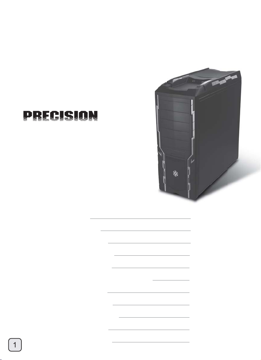
Precision crafted enclosure with class-leading
performance and features
Specifications
Disassemble Chart
Side panel installation
Power supply installation
Optical drive installation
3..5” / 2.5” hot-swappable HDD installation
Hard drive installation
Motherboard installation
Expansion card installation
Side panel installation
Fan filter removal steps
P.2
P.4
P.5
P.6
P.8
P.10
P.11
P.13
P.14
P.16
P.17
Page 3
PS06
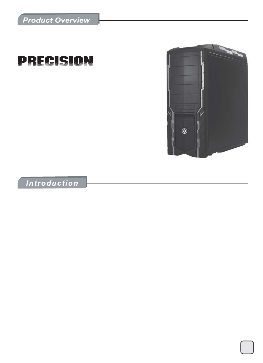
Precision crafted enclosure with class-leading
performance and features
Special Features
Positive air pressure design optimizes cooling performance
Quick removal dust filters
Mid-size tower chassis for all around integration
Great cooling performance with top mounted 180mm Air Penetrator fan
Convenient tool-less installation for nearly all components
All black painted interior
Hot-swappable hard drive bay for maximum flexibility
To push the thermal performance envelop of the Precision series to a new level,
SilverStone engineers implemented the award-winning 180mm Air Penetrator fan
(AP181) into the PS06 tower chassis. With the AP181 and an included silent 120mm
fan, the PS06 is capable of top-level cooling performance usually reserved for chassis
with twice the cost. Two additional 120mm fan slots lets users further improve cooling
performance if necessary . To help keep the dust out while providing great performance,
all intake fan slots are also equipped with easily removable fan filters to work effectively
with the default positive pressure airflow scheme. Ergonomic features from previous
Precision series have also been retained with tool-less mechanisms for all drive bays
along with a newly added external accessible 3.5”/2.5” combo hot-swappable bay on
the front panel for convenient hard drive storage. Rounding up this superb package
are all black interior, cable routing holes, anti-vibration hard drive brackets, dual USB
3.0 ports, and a daring new high-tech exterior styling. For enthusiasts looking for the
most advanced mid-tower chassis available at a great price, the Precision PS06 is a
great choice.
2
Page 4
PS06
Precision crafted enclosure with class-leading
performance and features
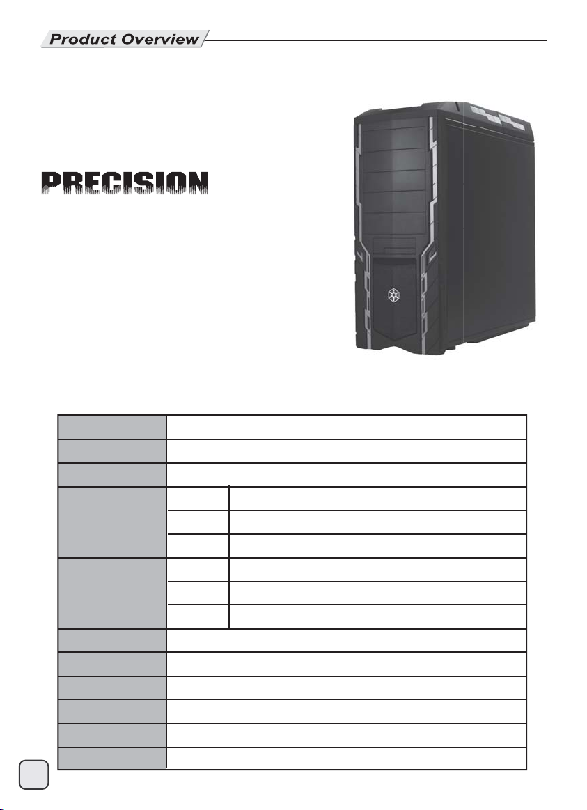
Specifications
3
Model No.
Material
Motherboard
Drive Bay
Cooling System
Expansion Slot
Front I/O Port
Power Supply
Expansion Card
Net Weight
Dimension
SST-PS06B (Black), SST-PS06B-W (Black+ window)
Plastic & mesh front panel, 0.7mm steel body
CEB, ATX up to 10.6”, Micro ATX
External
Internal
Front
Rear
Top
Bottom
8
USB 3.0 x 2, Audio x 1, MIC x 1
1 x Optional standard PS2 (ATX)
Compatible with expansion card up to 12.2”
9.05 kg
210mm(W) x 525mm(H) x 520mm(D)
5.25" x 5, 3.5” / 2.5” Hot swap bay
3.5" x 4
1 x 120mm intake fan
1 x 120mm fan slot
180mm Air Penetrator 700 / 1200rpm, 18 / 34dBA
1 x 120mm fan slot
Page 5
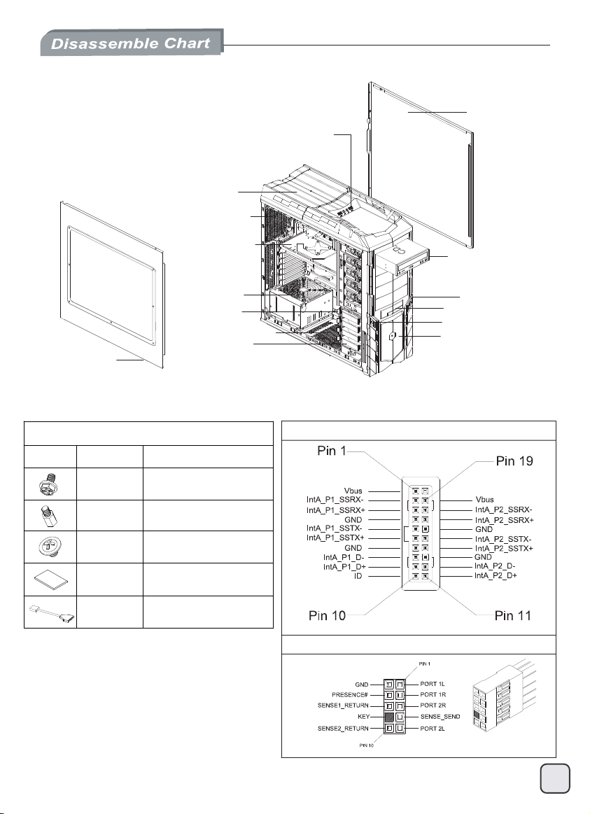
TOP I/O USB x 2 + SPK + MIC
18032 FAN x 1
12025 FAN x 1 (OPTION)
EXPANSION SLOTS
x 8 (OPTION)
RIGHT SIDE PANEL
5.25” DRIVE BAY x 5
SIDE PANEL WINDOW
PICTURE ITEM
SCREW A
SCREW B
SCREW C
MANUAL
USB CABLE
PACKAGE CONTENT
SECURE POWER SUPPLY
AND MOTHERBOARD
MOTHERBOARD STANDOFF
SECURE 5.25” DRIVE
PS2 PSU (OPTION)
3.5” HDD TRAY
12025 FAN x 1 (OPTION)
3.5” DRIVE BAY x 4
PURPOSE
AND FLOPPY
USB 3.0 TO USB 2.0
COVERTOR CABLE
RESET BUTTON
3.5” OR 2.5” HOTSWAP BAY x 1
POWER BUTTON
12025 FAN x 1
USB3.0 CONNETOR
HD AUDIO CONNETOR
4
Page 6
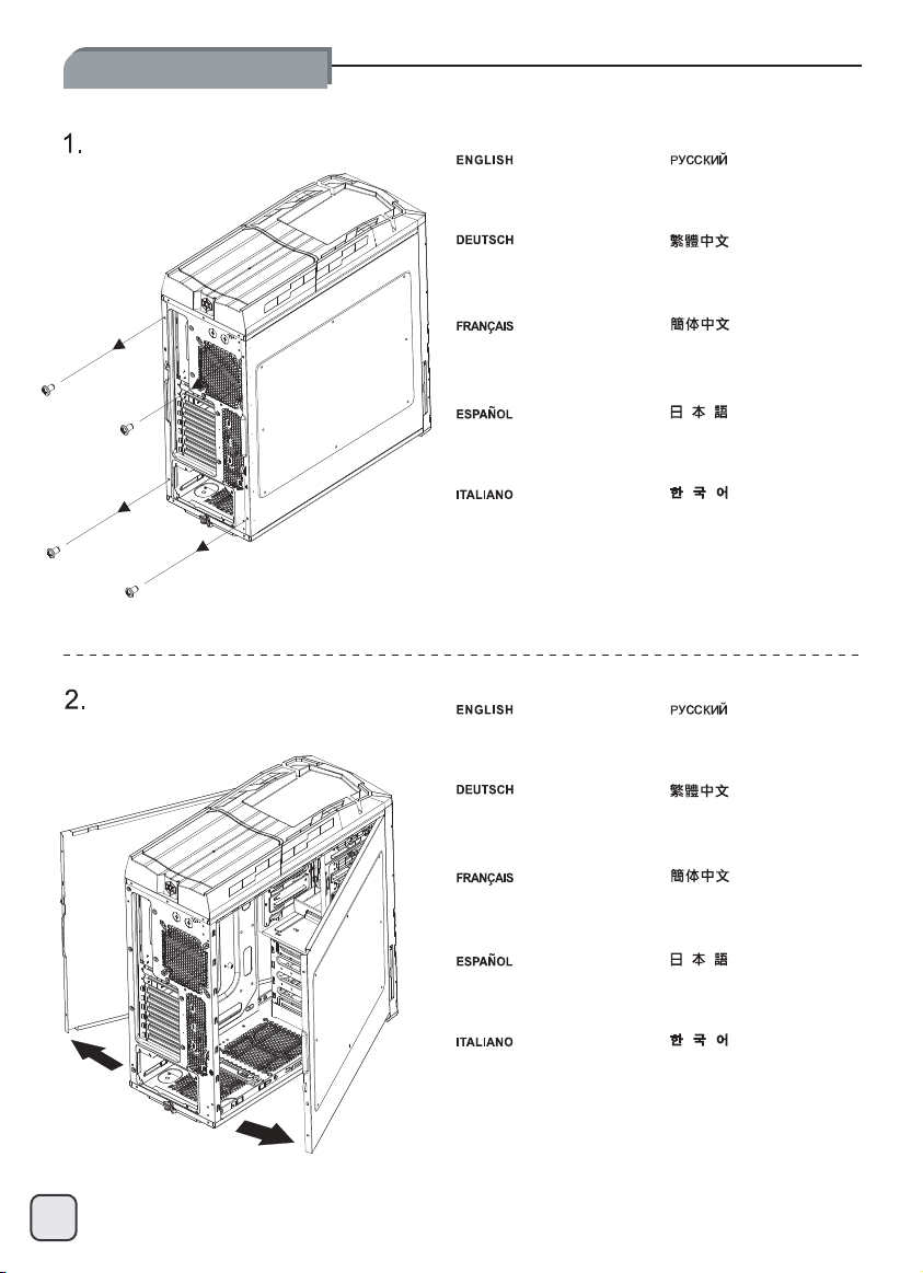
Side panel installation:
Unscrew screws from the
side panel.
Lösen Sie die Schrauben von
der seitlichen Blende.
Dévissez les vis du panneau
latéral.
Quite los tornillos del panel
lateral.
Rimuovere le viti dal pannello
laterale.
Remove side panels
from the case.
Entfernen Sie die seitlichen
Blenden vom Gehäuse.
Отвинтите винты на боковых
панелях.
先鬆開左右側板鎖固螺絲。
先松开左右侧板锁固螺丝。
側面パネルからネジをはず
します。
사이드패널에서 나사를
풀어 줍니다.
Снимите боковые панели с
корпуса.
取下側板。
Retirez les panneaux latéraux
du boîtier.
Quite los paneles laterales de
la carcasa.
Asportare il pannello laterale
dal case.
取下侧板。
側面パネルをケースから取り
外します。
사이드패널을 케이스에서 제거
합니다.
5
Page 7

Power supply installation:
1.
Unscrew screws from the
PSU holder.
Отвинтите винты на держателе
блока питания.
2.
Lösen Sie die Schrauben
von der Netzteilhalterung.
Dévissez les vis su support de
l'alimentation.
Quite los tornillos del soporte
de la FA.
Rimuovere le viti dal supporto
dell’alimentatore.
Install PSU into the case
as shown.
Installieren Sie das Netzteil
wie dargestellt im Gehäuse.
先鬆開底部鎖固電源支撐架的
兩顆螺絲。
先松开底部锁固电源支撑架的
两颗螺丝。
PSUホルダーからネジをはず
します。
PSU 홀더의 나사를 풀어줍니다.
Установите блок питания в корпус,
как показано на рисунке.
再放入電源。
Installez l'alimentation dans
le boîtier comme montré.
Instale la FA en la carcasa
como se muestra.
Installare l’alimentatore nel
case come mostrato.
再放入电源。
図のように、ケース内にPSUを
インストールします。
PSU를 그림과 같이 케이스에
장착합니다.
6
Page 8

Power supply installation:
3.
Adjust the PSU holder to fit the PSU.
Secure power supply and PSU holder with screws.
Richten Sie die Netzteilhalterung so aus, dass das
Netzteil hineinpasst.
Befestigen Sie Netzteil und Netzteilhalterung mit
Schrauben.
Ajustez le support pour bien fixer l'alimentation.
Fixez l'alimentation et son support avec des vis.
Ajuste el soporte de la FA para que se ajuste a la FA.
Fije la fuente de alimentación y el soporte de la FA con tornillos.
Ajuste el soporte de la FA para que se ajuste a la FA.
Fije la fuente de alimentación y el soporte de la FA con tornillos.
7
Отрегулируйте держатель блока питания по размеру
блока питания.
Закрепите блок питания и держатель блока питания
с помощью винтов.
根據電源長短,調整支撐架位置。
將支撐架及電源鎖固。
根据电源长短,调整支撑架位置。
将支撑架及电源锁固。
PSUに合わせて、PSUホルダーを調整します。
電源およびPSUホルダーをネジで固定します。
PUS 홀더를 조정해 PSU를 맞추어 넣습니다.
파워서플라이와 PSU 홀더를 나사로 고정시킵니다.
Page 9

Optical drive installation:
1.
Remove the front panel
as shown.
Снимите переднюю панель,
как показано на рисунке.
2.
Nehmen Sie die Frontblende
wie gezeigt ab.
Retirez le panneau frontal
comme montré.
Retire el panel frontal como
se muestra.
Rimuovere il pannello frontale
come mostrato in figura.
Remove the 5.25” drive bay
covers as shown.
Entfernen Sie die 5,25 ZollLaufwerkschachtabdeckungen
wie dargestellt.
先取下前塑膠面板。
先取下前塑料面板。
図示されるように、フロントパ
ネルを取り外します。
전편패널을 그림과 같이
제거합니다.
Снимите заглушки отсеков 5,25
дюйма, как показано на рисунке.
再移除5.25寸擋片。
Retirez les caches des baies
5.25” comme montré.
Retire las tapas para dispositivos
de 5,25” como se muestra.
Rimuovere i cover da 5.25” come
mostrato in figura.
再移除5.25寸挡片。
図示されるように、5.25インチ
のドライブベイカバーを取り外
します。
5.25” 드라이브베이 커버를
그림과 같이 제거합니다.
8
Page 10

Optical drive installation:
3.
Reinstall the front panel.
Установите на место
переднюю панель.
4.
Bringen Sie die vordere
Blende wieder an.
Réinstallez le panneau frontal. 然后将面板装回机壳。
Reinstale el panel frontal.
Reinstallare il pannello frontale.
Push the optical drive or 5.25”
device into the 5.25” drive bay
in all the way and PS06’s tool-less
mechanism will lock it automatically.
Schieben Sie das optische
Laufwerke oder 5,25 ZollLaufwerk bis zum Anschlag ein;
es wird automatisch verriegelt.
然後將面板裝回機殼。
フロントパネルを戻します。
전면패널을 재 설치합니다.
Вставьте привод оптических дисков
или другое устройство формата 5,25
дюйма в отсек 5,25 дюйма до упора
так, чтобы устройство автоматически
зафиксировалось механизмом корпуса
PS06, не требующим применения
инструментов.
將光碟機由前方裝入機箱,
免工具機構會自動將其固定。
Poussez l'appareil 5,25” dans la
baie 5,25” et fixez-le en poussant
le mécanisme sans outils dans la
direction montrée pour le fixer.
Empuje el dispositivo óptico ó
dispositivo de 5,25” dentro de la
bahía para dispositivos de 5,25”
hasta el fondo y el mecanismo
sin herramientas de la PS06 lo
enganchará de forma automática
Spingere il drive ottico o la periferica
da 5,25” nel bay fino a quando il
sistema di bloccaggio tool-less di
PS06 non bloccherà automaticamente
9
il dispositivo.
将光驱由前方装入机箱,
免工具机构会自动将其固定。
5,25インチデバイスを5,25イン
チドライブベイに入れ、工具不
要機構を押して固定します。
넣으면 PS06의 Tool-Less 메카니즘에
의해 자동으로 고정됩니다.
광드라이브 혹은 5.25” 장치를 5.25”
드라이브 베이로
끝까지 밀어.
Page 11

3..5”/2.5” hot-swappable HDD installation:
1.
Insert a 3.5” or 2.5” hard drive as shown.
Stecken Sie eine 3,5 Zoll- oder
2,5 Zoll-Festplatte wie dargestellt hinein.
Insérez un disque dur 3.5” ou 2.5”
comme montré.
Inserte un disco duro de 3,5” ó 2,5” como
se muestra.
Inserire un hard drive da 3,5” o 2,5”
come mostrato.
Установите 3,5- или 2,5-дюймовый жесткий диск,
как показано на рисунке.
依箭頭所示方向推動,便可輕鬆的插入硬碟。
依箭头所示方向推动,便可轻松的插入硬盘。
図のように、3.5インチまたは2.5インチの
ハードドライブを装着します。
3.5” 혹은 2.5” 하드 디스크를 그림과 같이 삽입합니다.
10
Page 12

Hard drive installation:
1.
Remove the hard drive tray
from the drive cage.
Извлеките лоток для жесткого
диска из корзины.
2.
Nehmen Sie den
Festplatteneinschub
aus der Halterung.
Retirez le support du disque
dur du casier.
Retire la bandeja para discos
duros de la carcasa para discos
duros.
Rimuovere il supporto hard
drive dalla gabbia.
Remove hard drive tray’s
locking clips.
Entfernen Sie die Fixierclips
vom Festplatteneinschub.
先將硬碟托盤取出。
先将硬盘托盘取出。
ハードドライブトレーをドライ
ブケージから取り出します。
하드 드라이브 트레이를 드라이브
케이지로 부터 제거합니다.
Извлеките фиксаторы из лотка
для жесткого диска.
移除硬碟托盤兩側的固定扣具。
11
Retirez les clips de verrouillage
du support du disque dur.
Retire los clips de enganche de
la bandeja para discos duros.
Rimuovere le clip di bloccaggio
dal supporto.
移除硬盘托盘两侧的固定扣具。
ハードドライブトレーのロック
ピンを取り外します。
하드 드라이브 트레이의 잠금
클립을 제거합니다.
Page 13

Hard drive installation:
3.
Insert the hard drive into the tray
and then secure it with the locking
clips.
Вставьте жесткий диск в лоток
и закрепите диск фиксаторами.
4.
Setzen Sie die Festplatte in den
Einschub ein, fixieren Sie die
Platte anschließend mit den
Fixierclips.
Insérez le disque dur dans son
support et fixez-le ensuite avec
les clips de verrouillage.
Inserte el disco duro en la
bandeja y asegúrelo con los
clips de enganche.
Inserire il disco rigido nel supporto
ed assicurarlo allo stesso per mezzo
delle clip di bloccaggio rimosse al
passo 2.
Insert the hard drive tray back
into the drive cage.
Setzen Sie den Festplatteneinschub
wieder in die Halterung.
將硬碟放入硬碟托盤並以扣具固定。
将硬盘放入硬盘托盘并以扣具固定。
ハードドライブをトレーに入れ
てから、ロックピンによって固
定します。
전편패널을 그림과 같이
제거합니다.
Вставьте лоток для жесткого
диска в корзину.
再將硬碟托盤裝回硬碟架。
Remettez le disque dur avec son
support dans le casier à disques
durs.
Inserte de nuevo la bandeja para
discos duros en la carcasa para
discos duros.
Inserire quindi il disco rigido
nella gabbia.
再将硬盘托盘装回硬盘架。
ハードドライブトレーをドライ
ブケージに戻します。
5.25” 드라이브베이 커버를
그림과 같이 제거합니다.
12
Page 14

Motherboard installation:
1.
Install all motherboard standoffs
that are needed by the motherboard.
Разверните корпус набок, как
показано на рисунке и установите
все необходимые опоры материнской
платы.
2.
Platzieren Sie das Gehäuse wie
auf dem Bild gezeigt, und installieren
Sie alle Motherboardhalter, die Ihr
Motherboard benötigt.
Placez le boîtier à plat comme
montré et vissez tout les plots
nécessaires pour votre carte mère.
Coloque la caja como se muestra
e instale los separadores de la
placa base que sean necesarios.
Coloque la placa base sobre los
separadores y fijela con los tornillos.
Place the motherboard into the
case over the standoffs and secure
with screws.
Positionieren Sie Ihr Motherboard
über den Motherboardhaltern und
befestigen Sie es mit den Schrauben.
請依需求將主機板螺柱鎖固於機殼。
请依需求将主机板螺柱锁固于机壳。
図のようにマザーボードに必要
なスペーサーをケースに全てイ
ンストールします。
케이스를 보는 바와 같이 놓고,
메인보드 장착을 위한 지지 나사를
장착한다.
Поместите материнскую плату
в корпус на опоры и закрепите
шурупами.
將主機板裝入機殼,用螺絲將其鎖固。
13
Placez la carte mère dans le
boîtier sur les plots et fixez-la
avec des vis.
Coloque la placa base sobre los
separadores y fijela con los tornillos.
Collocare la scheda madre nel
case sui distanziatori e fissare
con le viti.
将主机板装入机壳,用螺丝将其锁固。
ケースのスペーサー上にマザーボ
ードを取付け、ネジで固定します。
케이스 안의 지지나사 위에
메인보드를 넣고, 나사로 고정시킨다.
Page 15

Expansion card installation:
1.
Loosen the expansion card’s
tool-less mechanism.
Ослабьте механизм фиксации
платы расширения, не требующий
применения инструментов
.
2.
Lösen Sie den Mechanismus am
Erweiterungskartensteckplatz.
Desserrez le mécanisme sans
outils des cartes d'extension.
Afloje el mecanismo sin herramientas
para la tarjeta de expansión.
Allentare il meccanismo tool-less
delle schede di espansione.
Remove the required expansion
slot covers, the second to sixth
covers are not reusable once
removed.
Entfernen Sie die jeweiligen
Steckplatzabdeckungen; beachten
Sie dabei, dass die Abdeckungen
2 – 6 nicht wiederverwendet werden
können.
鬆開鎖固擴充卡擋片螺絲。
松开锁固扩充卡挡片螺丝。
拡張カードの工具不要機構
を緩めます。
확장카드의 tool-less 메카니즘을
풀어 줍니다.
Снимите необходимые заглушки
слота расширения. Заглушки со
второй по шестую нельзя использоват ь
повторно.
取下擴充卡擋片。
Retirez les caches des
\emplacements d'extension, le
deuxième des six caches ne plus
être réutilisé une fois retiré.
Retire las cubiertas de la ranura
de la tarjeta de expansión. Las
cubiertas de la segunda hasta la
sexta no son reutilizables una vez
se retiren.
Rimuovere i necessari cover degli
slot di espansione, il secondo ed il
sesto cover non sono riutilizzabili
se rimossi.
取下扩充卡挡片。
必要な拡張スロットカバーを取
り外します。2番目から6番目の
カバーは一度外すと戻せません。
필요한 확장 슬롯의 커버를
제거합니다. 2번째에서 6번째의
커버는 제거하면 재 사용이 불가합니다.
14
Page 16

Expansion card installation:
3.
Install and secure required expansion cards.
Installieren und fixieren Sie benötigte Erweiterungskarten.
Installez et fixez les cartes d'extensions nécessaires.
Instale y fije las tarjetas de expansión necesarias.
Installare ed assicurare al case le schede di espansione in vostro possesso.
15
Вставьте и закрепите карту расширения.
安裝並鎖固需要的擴充卡。
安装并锁固需要的扩充卡。
必要な拡張カードをインストールし、固定します。
필요한 확장카드를 설치하고 고정시킵니다.
Page 17

Side panel installation:
1.
Make sure all necessary cables and wires are connected, then reinstall the panels and secure with screws.
Stellen Sie sicher, daß alle erforderlichen Kabel und Drähten verbunden sind, dann installieren Sie die Platten wieder
und sichern Sie sie mit Schrauben.
Vérifiez bien que tout les câbles nécessaires sont correctement branchés, puis remettez les panneaux latéraux et fixez-les
avec les vis préalablement démontées.
Asegurese de que todo los cables estén conectados y reinstale los paneles sujetandolos con los tornillos.
Assicurarsi che tutti cavi siano connessi, quindi reinstallare i panelli e fissare con le viti.
Убедитесь, что все кабели и провода подключены, затем поставьте на место левую и правую панели и закрепите их шурупами.
接好所有需要的線材之後,再將左右側板裝回機殼,並以螺絲鎖固。
接好所有需要的线材之后,再将左右侧板装回机壳,并以螺丝锁固。
全てのケーブル接続および配線を確認したら、パネルを戻してネジ固定します。
필요한 모든 케이블과, 선들이 연결되었는지를 확인하고, 패널을 재 설치한 후 나사로 고정시키십시요.
16
Page 18

Fan filter removal steps:
1.
Please remove the fan filter
as shown.
Снимите фильтр вентилятора,
как показано на рисунке.
2.
Bitte entfernen Sie den Filter
des Lüfters wie angezeigt.
Veuillez retirer le filtre du
ventilateur de comme montré.
Por favor, quite el filtro del
ventilador de como se muestra.
Rimuovere il filtro della ventola
da come mostrato.
Push the filter from one side of
the front panel to pull out from
the opposite side.
Drücken Sie den Filter von einer
Seite der Frontblende so weit,
dass Sie ihn von der Gegenseite
herausziehen können.
底部濾網可從後方直接拉出。
底部滤网可从后方直接拉出。
図のように ファンフィルタを
取り外します。
팬 필터를 그림과 같이 제거합니다.
Протолкните фильтр с одной
стороны передней панели,
чтобы его можно было вытянуть
с противоположной стороны.
前面板濾網從側面用力推可取出
(左右兩邊都可取出)。
17
PUSH
Poussez le filtre par un côté du
panneau frontal pour le tirez vers
le côté opposé.
Empuje el filtro desde un lado del
panel frontal para sacarlo por el
lado opuesto.
Spingere il filtro da una parte del
pannello frontale per estrarlo dalla
parte opposta.
前面板滤网从侧面用力推可取出
(左右两边都可取出)。
フロントパネルの一方からフィ
ルタを押して反対側から取り外
します。
필터를 전면패널의 한쪽에서
반대편으로 밀어 제거합니다.
Page 19

Page 20

Issue date: Februsry, 2010
NO: G11213630
 Loading...