

Page 1
ML03
Page 2
Product Overview
ML03
The entry-level HTPC benchmark
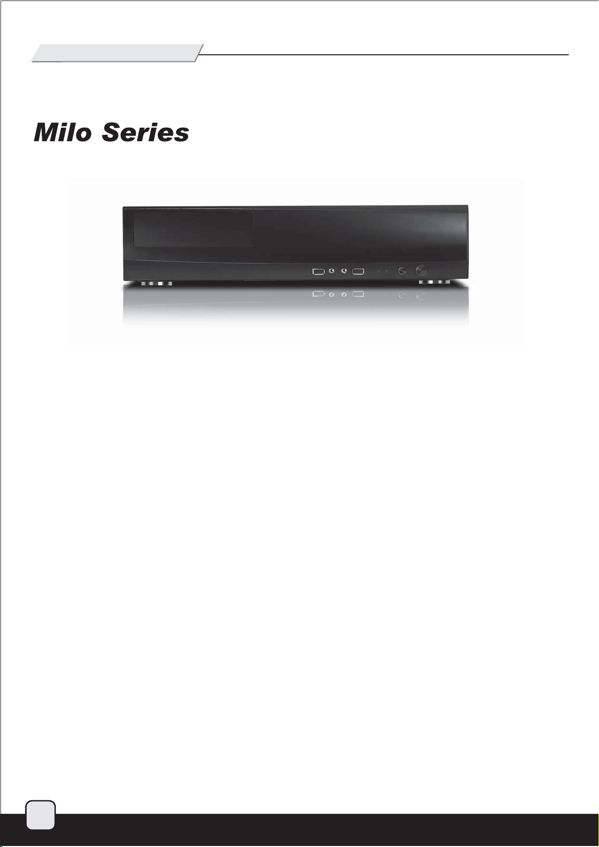
Continuing where the popular Grandia GD05 left off, the Milo ML03
HTPC case again combines the full size features of Grandia series with
small form factor dimensions. The slimmer Milo ML03 has a profile of
105mm height and 340mm depth, making it extremely easy to integrate
into any living room furniture. Incredibly, this case can accommodate
up to three 3.5” hard drives or five 2.5” HDD/SSD through its smartly
designed drive cages that can mount either size without any use of
adapters. For cooling, the ML03 can be fitted with up to four 80mm fans
so users can choose to build a quiet system with low power components
or a powerful HTPC with 140W CPU if needed. There are also numerous
small touches including pre-cut hole for VGA (D-SUB) connector,
Kensington lock support, and an additional full size expansion slot for
installing extra motherboard I/O, fan controller, or accessories products
such as CLEARCMOS. For those looking to build an HTPC with good
expansion and cooling capability but has limited room and budget, the
SilverStone Milo ML03 is the one to get.
1
Page 3
Product Overview
ML03
The entry-level HTPC benchmark
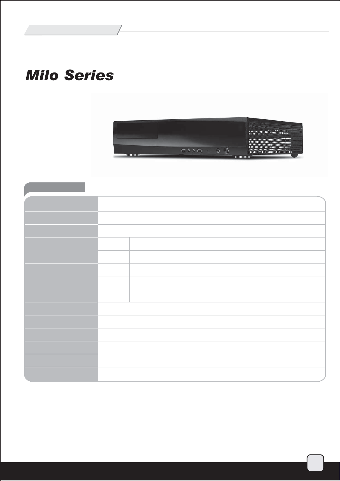
Specification
Model No.
Material
Motherboard
Drive Bay
Cooling System
Expansion Slot
Front I/O Port
Power Supply
Expansion Card
Net Weight
SST-ML03B (black)
Aluminum skin reinforced plastic front panel, 0.8mm SECC body
Micro ATX, Mini-DTX, Mini-ITX
External
Internal
Right
Top
Left
4 low profile + 1 utility
USB 3.0 x 2, Audio x 1, MIC x 1
1 x standard PS2 (ATX), depth limit = 140mm
4 x low profile
3.3 kg
5.25" x 1 (compatible with one 3.5” HDD or two 2.5” HDD/SSD)
3.5" x 2 (compatible with one 2.5” HDD each), 2.5” x 1
4 x 80 mm fan slot
Oversized CPU vents
Hard drive vents
Dimension
440 mm (W) x 105 mm (H) x 340 mm (D)
2
Page 4
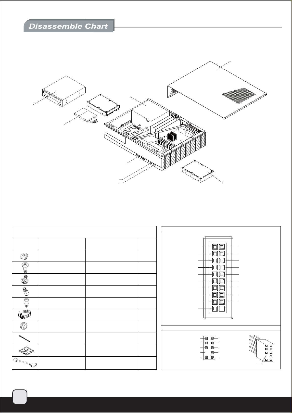
5.25” BAY
TOP COVER
PS2 PSU (OPTION)
2.5” OR 3.5”
DRIVE BAY (HDDEN)
USB 3.0 x 2 + SPK + MIC
PICTURE ITEM
SCREW A
SCREW B
SCREW C
SCREW D
SCREW E
WIRE MOUNT
RESET BUTTON
POWER BUTTON
PACKAGE CONTENT
SECURE 5.25” DEVICE
SECURE HARD DEVICE
SECURE POWER SUPPLY OR
PSU BKT AND MOTHERBOARD
SECURE MOTHERBOARD
SECURE 5.25” DEVICE
SECURE TIE WIRE
PURPOSE Q’TY
AND 2.5 HDD
3.5” DRIVE BAY (HDDEN)
USB 3.0 CONNECTOR
ID INTA_P2_D+
23
8
16
1
1
1
INTA_P1_D+
INTA_P1_D-
GND
INTA_P1_SSTX+
INTA_P1_SSTX-
GND
INTA_P1_SSRX+
INTA_P1_SSRX-
VBUS
INTA_P2_DGND
INTA_P2_SSTX+
INTA_P2_SSTXGND
INTA_P2_SSRX+
INTA_P2_SSRXVBUS
3
HDD RUBBER
BUNCH WIRE TIES
FAN FILTER
USB CABLE 1
SECURE HDD
SECURE TIE WIRE
USB 3.0 TO USB 2.0
COVERTOR CABLE
4
5
1
HD AUDIO CONNECTOR
AUD GND PORTIL
PRESENCE
SENSE1_RETURN
PIN
SENSE2_RETURN
PORT1R
PORT2R
SENSE_SEND
PORT2R
PIN
Page 5
1.
简体 中文
繁体 中文
简体 中文
繁体 中文
简体 中文
繁体 中文
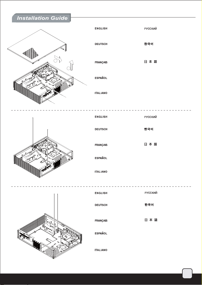
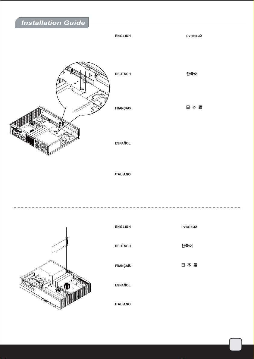
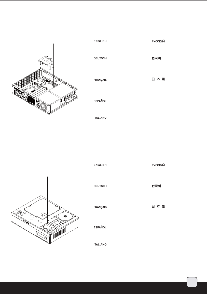
Unscrew the three screws
from the rear of the chassis
then remove the top cover.
Отвинтите три винта с задней части
корпуса, затем снимите верхнюю
крышку.
2.
Lösen Sie die drei Schrauben
von der Rückseite des Gehäuses,
entfernen Sie dann die obere
1
2
Abdeckung.
Dévissez les trois vis à l'arrière de
boîtier et ensuite retirez le panneau
supérieur.
Destornille los tres tornillos de la
parte posterior del chasis y luego
retire la cubierta superior.
Svitare le tre viti sul retro dello
chassis per rimuovere il cover
superiore.
Unscrew two screws from the
center brace to remove it.
Lösen Sie die beiden Schrauben
von der mittleren Verstärkung,
nehmen Sie sie heraus.
Dévissez les deux vis fixant la
barre centrale pour la retirer.
Destornille los dos tornillos del
soporte central para retirarlo.
Svitare le due viti dal sostegno
centrale per rimuoverlo.
케이스 뒷편의 3개의 나사를 풀은뒤
상부 커버를 제거합니다.
ケースの後ろからネジ3本を外し、
それから上部カバーを取り外します。
繁体中文
先用螺絲起子,
鬆開三顆螺絲在取下上方蓋子。
简体中文
先用螺丝起子,
松开三颗螺丝在取下上方盖子。
Отвинтите два винта с центральной
скобы, чтобы снять ее.
중심 브레이스에서 두개의 나사를
풀어 제거합니다.
センターブレースからネジ2本
を外して、取り外します。
繁体中文
鬆開光碟架二顆螺絲,卸下中支架。
简体中文
松开光盘架二颗螺丝,卸下中支架。
3.
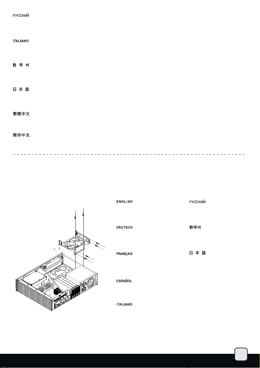
Unscrew screws from the hard
drive bracket to remove it.
Lösen Sie die Schrauben der
Festplattenhalterung, entfernen
Sie sie.
Dévissez les vis du casier à
disques durs pour le retirer.
Quite los tornillos del bracket del
disco duro para retirarlo.
Svitare le viti del supporto
hard drive per rimuoverlo.
Отвинтите винты с держателя
жесткого диска, чтобы снять его.
하드 드라이브 브라켓을 제거하기
위해 나사를 제거합니다.
ハードドライブブラケットのネ
ジを外して、取り外します。
繁体中文
鬆開硬碟架螺絲,卸下硬碟架。
简体中文
松开硬盘架螺丝,卸下硬盘架。
4
Page 6
4.
简体 中文
繁体 中文
2
1
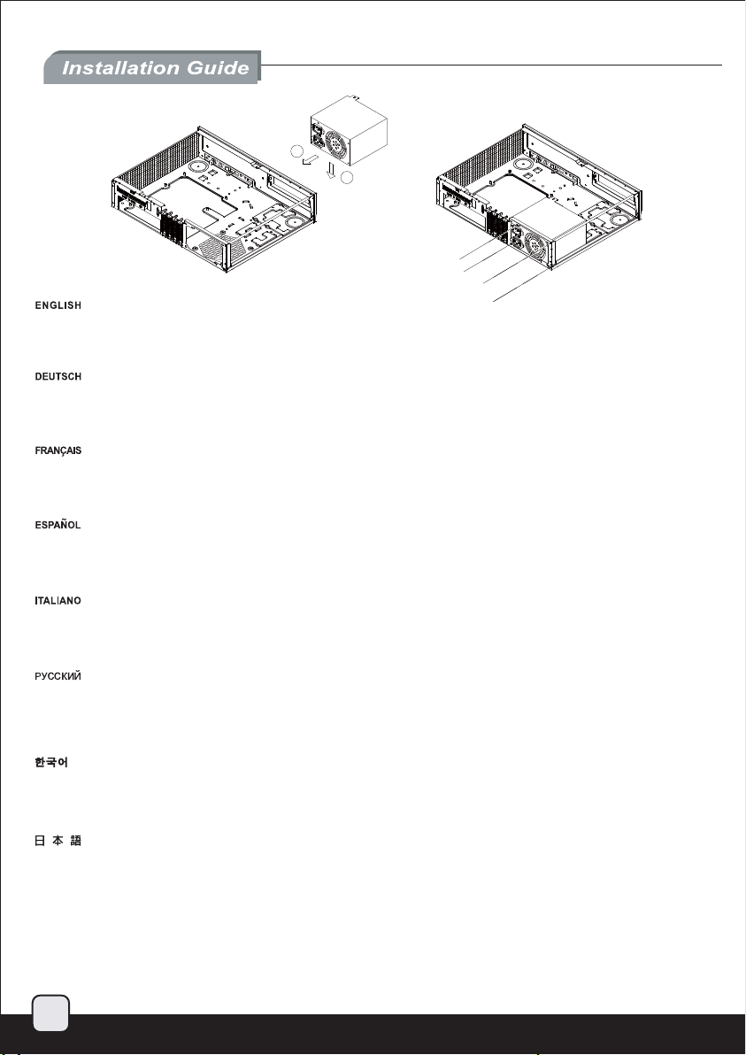
Install power supply into the case. Please note the case supports mounting power supply in two different orientations.
If you use a power supply with 80mm fan, you can freely choose either orientation for easier cable management as needed.
If you use a power supply with 120mm fan or bigger, you must install it with the fan facing down.
(For more information regarding power supply size limitations, please refer to the component guide in later pages)
Installieren Sie das Netzteil im Gehäuse. Bitte beachten Sie, dass das Gehäuse die Montage des Netzteils in zwei verschiedenen Ausrichtungen
unterstützt. Wenn Sie ein Netzteil mit 80 mm-Lüfter nutzen, können Sie die Ausrichtung wie gewünscht zur Vereinfachung der Kabelverwaltung
anpassen. Wenn Sie ein Netzteil mit einem 120 mm- oder größeren Lüfter nutzen, muss der Lüfter bei der Installation nach unten gerichtet sein.
(Weitere Informationen zur Beschränkung der Netzteilgröße entnehmen Sie bitte der Komponentenanleitung weiter hinten)
Installez l'alimentation dans le boîtier. Veuillez noter que le boîtier permet le montage des alimentations dans les deux sens.
Si vous utilisez une alimentation avec un ventilateur de 80mm, vous pouvez librement choisir le sens selon la facilité de câblage que cela
vous accordera. Si vous utilisez une alimentation avec un ventilateur de 120mm ou plus, vous devez l'installez avec le ventilateur vers le bas.
(Pour plus d'informations sur les limitations des tailles des alimentations, veuillez-vous référer au guide des composant dans les pages à venir)
Instale la fuente de alimentación en la carcasa. Por favor, tenga en cuenta que la carcasa monta la fuentes de alimentación orientada de dos
modos distintos. Si usa una fuente de alimentación con un ventilador de 80mm, puede escoger la orientación que prefiera para así ordenar
mejor los cables. Si usa una fuente de alimentación con un ventilador de 120mm ó mayor, debe hacerlo con el ventilador hacia abajo. (Para más
información sobre las limitaciones de tamaño de la fuente de alimentación, consulte por favor la guía de componentes en páginas posteriores).
Installare l’alimentatore nel case. L’alimentatore può essere orientato in due modi differenti. Se state installando un alimentatore con ventola da
80mm, potete scegliere liberamente entrambe le posizioni optando per quella che meglio favorisce una facile sistemazione dei cavi. Se invece
utilizzate un alimentatore con ventola da 120mm o più grande, dovete installarlo con la ventola rivolta verso il basso
(per maggiori informazioni in merito alle limitazioni di misura degli alimentatori, fate riferimento a quanto esposto nelle pagine successive)
Установите источник питания в корпус. Обратите внимание, что можно установить источник питания в двух разных направлениях.
При использовании источника питания с вентилятором 80 мм можно использовать любое направление для упрощения расположения
кабелей. При использовании источника
вентилятор был направлен вниз. (для получения дополнительной информации относительно ограничений размера источников питания
см. руководство к компонентам далее).
파워 서플라이를 케이스에 설치합니다. 이 케이스는 파워 서플라이를 두개의 방향을 설치 가능합니다. 만약
사용한다면, 케이블 정리가 손쉬운 쪽을 선택해 설치 바랍니다. 만약 120mm 혹은 그 이상의 팬을 사용하는 파워 서플라이를 사용할 경우,
팬이 아래쪽을 향하도록 설치하면 됩니다. (만약 파워 서플라이의 크기 및 제한에 대한 자세한 정보를 확인하려면, 뒤에 나오는 부품
가이드를 참조 바랍니다. )
ケースに電源をインストールします。ケースは2つの異なる方向での電源設置をサポートしていることにご注意ください。80mmファン装備の電源を
使う場合、必要に応じてケーブルを容易に取り回せる向きを自由に選ぶことができます。120mmファンまたはより大型ファン装備の電源を使う場合、
ファンを下向きに設置します。(電源サイズ制限の詳細については、後のページに記載のコンポーネントガイドをご参照ください。)
繁体中文
安裝電源供應器,請注意此機殼的正反裝設計,是為了讓您使用8公分電源風扇時,選擇性調整電源出線位置,如果您使用12公分風扇電源,
請一定要將風扇朝下,以免風扇吸不到風。(關於電源供應器的長度規格,請參考元件尺寸限制)
简体中文
安装电源供应器,请注意此机壳的正反装设计,是为了让您使用8公分电源风扇时,选择性调整电源出线位置,如果您使用12公分风扇电源,
请一定要将风扇朝下,以免风扇吸不到风。(关于电源供应器的长度规格,请参考组件尺寸限制)
питания с вентилятором 120 мм или более следует устанавливать его таким образом, чтобы
파워 서플라이가 80mm팬을
5
Page 7
5.
简体 中文
繁体 中文
Insert the I/O shield included with
your motherboard, then install the
motherboard into the case.
Установите панель ввода/вывода
материнской платы, затем установите
материнскую плату в корпус.
6.
Bringen Sie die bei Ihrem Motherboard
mitgelieferte Anschlussblende an,
installieren Sie dann das Motherboard
im Gehäuse.
Insérez la plaque des ports E/S inclus
avec votre carte mère, puis mettez la
carte mère dans le boîtier.
Inserte el escudo de E/S incluido con
su placa base, luego instale la placa
base en la carcasa.
Installate il pannello I/O della scheda
madre, quindi la scheda madre stessa.
메인보드와 동봉된 I/O 커버를 삽입한 후,
메인보드를 케이스에 설치합니다.
マザーボードに付属のI/Oシールドを
装着してから、ケース内にマザーボ
ードを取り付けます。
繁体中文
塞入I/O彈片,裝入主機板。
简体中文
塞入I/O弹片,装入主机板。
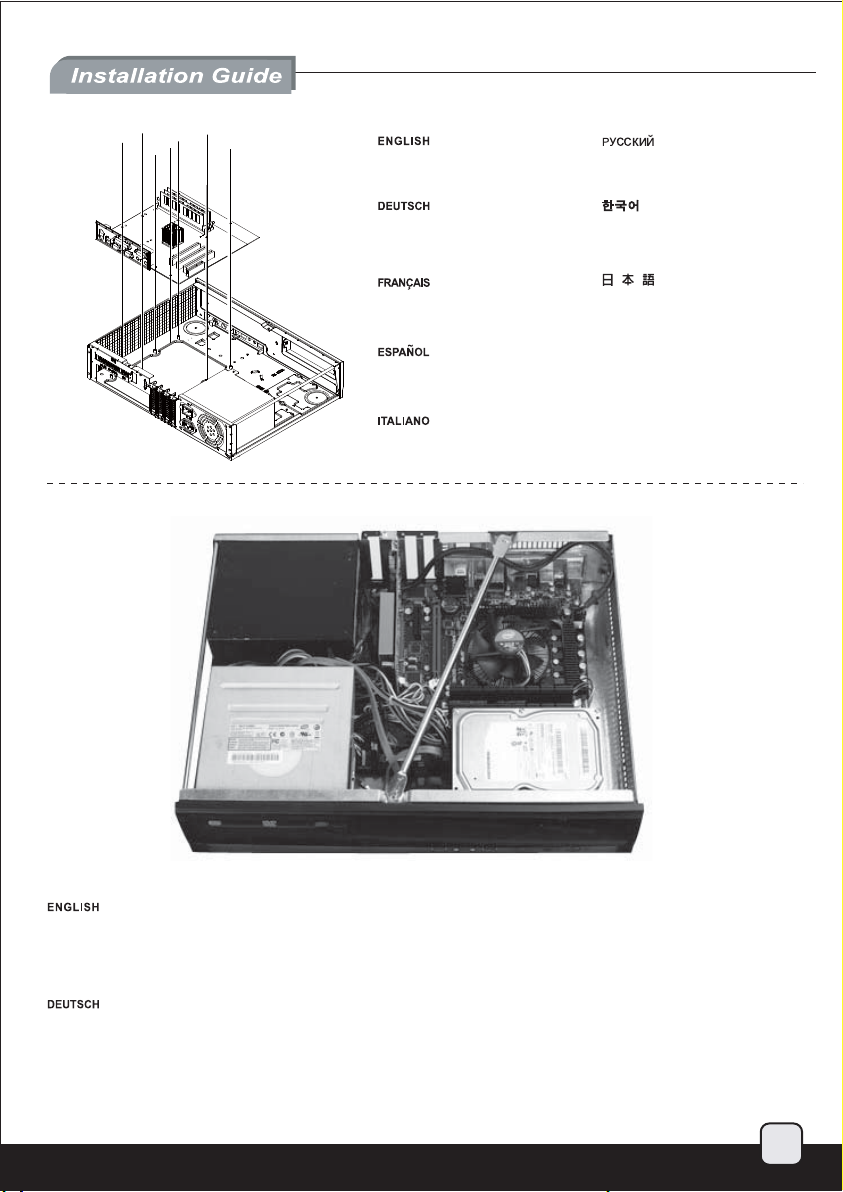
We recommend at this point to start thinking about routing the cables cleanly before connecting them to the motherboard, cables include fan
cables, power supply 24pin cable, CPU ATX 4pin/EPS12V 8pin, front panel connectors, and front I/O connectors.
Bereits ab diesem Schritt sollten Sie sich Gedanken über eine saubere Kabelführung machen, bevor Sie Anschlüsse am Motherboard
vornehmen; beachten Sie sämtliche Kabelanschlüsse (Lüfterkabel, 24-poliges Netzteilkabel, CPU-Kabel (4-polig, ATX / 8-polig, EPS12V),
Anschlüsse der Frondblende, E/A-Frontanschlüsse).
6
Page 8
简体 中文
繁体 中文
Nous vous recommandons de commencer dés à présent à réfléchir au routage des câbles avant de les branchez à la carte mère, câbles incluant
les câbles de ventilateurs, le câble 24 pin de l'alimentation, le connecteur de processeur ATX 4pin/EPS12V 8pin, les connecteurs du panneau
frontal, et les ports d'E/S.
Llegados a este punto le recomendamos que empiece a pensar sobre enrutar los cables de un modo limpio antes de conectarlos a la placa base.
Los cables incluyen los de los ventiladores, el de 24 pines de la fuente de alimentación, el de la CPU 4 pines ATX/8 pines EPS 12V, los conectores
del panel frontal y los conectores frontales de E/S.
A questo punto vi raccomandiamo di iniziare a pensare a come sistemare I cavi dell’alimentatore prima di connetterli alla scheda madre. Nello
specifico i cavi delle ventole, il connettore a 24pin, il connettore ATX 4pin/EPS12V 8pin, I connettori del pannello frontale e quelli I/O sempre frontali.
На этом шаге рекомендуется продумать, как будут проложены кабели до их подсоединения к материнской плате: кабели вентилятора,
24-контактный кабель источника питания, 4-контактный кабель ЦП ATX/8-контактный EPS 12 В, разъемы на передней панели и передние
разъемы ввода/вывода.
이 시점에서 메인보드에 케이블 연결을 어떻게 해야 할지 잘 고려해 봐야 합니다. 케이블은 팬 케이블, 파워 서플라이 24핀 케이블, CPU ATX
4Pin/EPS12V 8V 핀, 전면 패널 커넥터 및 전면 I/O 커넥터 등입니다.
この時点でマザーボード、ファンケーブル、電源24ピンケーブル、CPU ATX 4ピン/EPS12V 8ピン、フロントパネルコネクタ、およびフロント
I/Oコネクタと接続する前にケーブル取り回しをすっきりさせることを考慮し始めるようお勧めします。
繁体中文
我們建議你在安裝主機板之前即開始準備整線動作。包含風扇電源線, PSU 24Pin接線 , CPU ATX 4Pin/EPS 8Pin接線, Front Panel Connectors
與Front I/O Connectors。
简体中文
我们建议你在安装主机板之前即开始准备整线动作。包含风扇电源线, PSU 24Pin接线 , CPU ATX 4Pin/EPS 8Pin接线, Front Panel Connectors
与Front I/O Connectors。
7
Page 9
7.
简体 中文
繁体 中文
简体 中文
繁体 中文
The tray areas around the motherboard
have many small pass-through holes
that can be used with included wire tie,
please refer to the illustration for more
information.
Области лотка вокруг материнской
платы оснащены большим
количеством сквозных отверстий,
которые можно использовать с
прилагаемой проволочной стяжкой,
для получения дополнительной
информации см. рисунок.
8.
Der Bereich rund um das Motherboard
verfügt über zahlreiche kleine Löcher,
die in Kombination mit den mitgelieferten
Kabelbindern verwendet werden können;
weitere Informationen entnehmen Sie
bitte der Abbildung .
Les panneaux intérieurs autour de la
carte mère possèdent de nombreux
trous qui peuvent être utilisé avec les
crochets pour y faire passer les câbles,
veuillez vous référer aux illustrations
pour plus d'informations.
Las zonas de la bandeja alrededor de la
placa base tienen muchos pequeños
agujeros de pasada que pueden usarse
con las bridas incluidas, por favor consulte
la ilustración para tener más información.
Le aree intorno alla scheda madre hanno
diversi fori per il passaggio dei cavi che
possono essere usati in combinazione con
le fascette in dotazione, fare riferimento
all’illustrazione per maggiori informazioni.
Install and secure required
expansion cards.
Installieren und befestigen Sie die
erforderlichen Erweiterungskarten.
메인보드 주변의 트레이에 많은
구멍들이 있어 동봉된 케이블 타이를
이용해 케이블을 손쉽게 정리할 수
있습니다. 더 자세한 내용은, 그림을
참조하시기 바랍니다.
マザーボード周辺のトレーエリアは、
付属のケーブルストラップに使用で
きる多くの小さなケーブル通し穴が
開いています。詳細については図を
ご参照ください。
繁体中文
主機板週邊備有許多供綁線用的凸橋,
可配合零件包所附的束線帶使用,
請參考上圖使用。
简体中文
主机板外围备有许多供绑线用的凸桥,
可配合零件包所附的束线带使用,
请参考上图使用。
Установите и закрепите необходимые
платы расширения.
필요한 확장카드를 설치하고
고정시킵니다.
Installez et fixez les cartes
d'extension requises.
expansión necesarias.
Installare ed assicurare le schede
di espansione necessarie.
必要とされる拡張カードをインスト
ールし、固定します。
繁体中文
安裝並鎖固介面卡。Instale y fije las tarjetas de
简体中文
安装并锁固适配卡。
8
Page 10
9.
简体 中文
繁体 中文
Install and secure any 3.5” or 2.5” hard drive into the hard drive bracket on the right side with screws.
The hard drive cage is designed to reduce vibration so the screws may not feel completely fastened as a result, this is normal.
The drive cage material is made out of industrial grade nylon so it is flexible and resistant to breaking.
Installieren und befestigen Sie eine 3,5 Zoll- oder 2,5 Zoll-Festplatte mit Schrauben in der Festplattenhalterung auf der rechten Seite.
Der Festplattenkäfig dient der Kompensation von Vibrationen; dadurch entsteht möglicherweise der Eindruck, die Schrauben ließen
sich nicht richtig festziehen. Dies ist ganz normal. Der Laufwerkskäfig besteht aus hochwertigem Nylon (Industriequalität); dies macht
ihn flexibel und bruchfest.
Installez et fixez tout disque dur 3.5” ou 2.5” dans le casier du côté droit avec des vis. Le casier à disques dur est conçu pour réduire
les vibrations donc les vis ne sembleront pas être complètement vissé, ce qui est normal.
Le matériau utilisé pour le casier est fabriqué à partir de nylon de qualité industrielles qui est flexible et résistant à la casse.
Instale y fije cualquier disco duro de 3,5” ó 2,5” en el bracket para discos duros del lado derecho con tornillos. La carcasa para discos
duros está diseñada para reducir la vibración, luego los tornillos puede parecer que no estén apretados del todo, esto es algo normal.
El material de la carcasa para discos es de nylon industrial, luego es flexible y resistente a las roturas.
Installare ed assicurare con le viti in dotazione gli hard disk da 3,5” o 2,5” nel supporto specifico. Il supporto è stato progettato per ridurre
le vibrazioni, per cui le viti potrebbero non sembrare completamente serrate, è normale. Il supporto è in nylon ad alta resistenza, per cui
risulta flessibile.
Установите и закрепите винтами жесткий диск 3,5 или 2,5 дюйма в держатель для жесткого диска с правой стороны. Корпус
жесткого диска разработан специальным образом для снижения уровня вибрации, поэтому может показаться, что винты
закреплены не полностью, это нормально. Корпус жесткого диска изготовлен из промышленного нейлона,
гибким и устойчивым к ударам.
3.5" 혹은 2.5" 하드 드라이브를 하드 드라이브 브라켓에 설치 한 후 오른쪽에 나사로 고정시킵니다.
하드 드라이브 케이지는 진동을 방지하도록 설계되어 있어 나사가 완전히 고정된 느낌이 들면 정상 상태입니다. 드라이브 케이지
재질은 산업용 규격의 나일론으로 제작되어 있어 유연하고 강도가 높아 쉽게 부서지지 않습니다.
右側のハードドライブブラケットの中に任意の3.5インチまたは2.5インチのハードドライブを取付け、ネジで固定します。 ハードドライ
ブケージは振動を減少させるよう設計されているので、結果としてネジが完全に締め付けられない感じがありますが、これで正常です。
ドライブケージ素材は産業用ナイロンから作られているので、柔軟で耐破壊性があります。
繁体中文
將3.5"硬碟或2.5"硬碟裝入右方硬碟架,並鎖固螺絲。
(3.5"硬碟架有整合防震的設計,鎖固點較軟是正常現象,此磁架是用高韌性的尼龍材料製作,請安心使用)
简体中文
将3.5"硬盘或2.5"硬盘装入右方硬盘架,并锁固螺丝。
(3.5"硬盘架有整合防震的设计,锁固点较软是正常现象,此磁架是用高韧性的尼龙材料制作,请安心使用)
поэтому он является
9
Page 11
10.
简体 中文
繁体 中文
简体 中文
繁体 中文
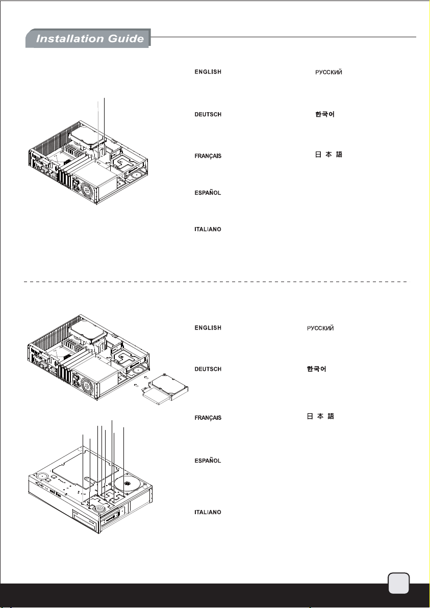
Reinstall hard drive bracket back into
the case and be careful of the cables
and wirings below.
Установите кронштейн для
жесткого диска в корпус,
соблюдая осторожность, чтобы
не задеть кабели и проводку.
11.
Installieren Sie die Festplattenhalterung
wieder im Gehäuse; achten Sie auf die
darunter befindlichen Kabel und Drähte.
Réinstallez le casier à disques dur dans
le boîtier et faîtes attention aux câbles.
en la carcasa y tenga cuidado con los
cables que están debajo.
Reinstallare il supporto hard disk con
le periferiche di storage montate,
assicurandosi che non interferisca con
i cavi al di sotto dello stesso.
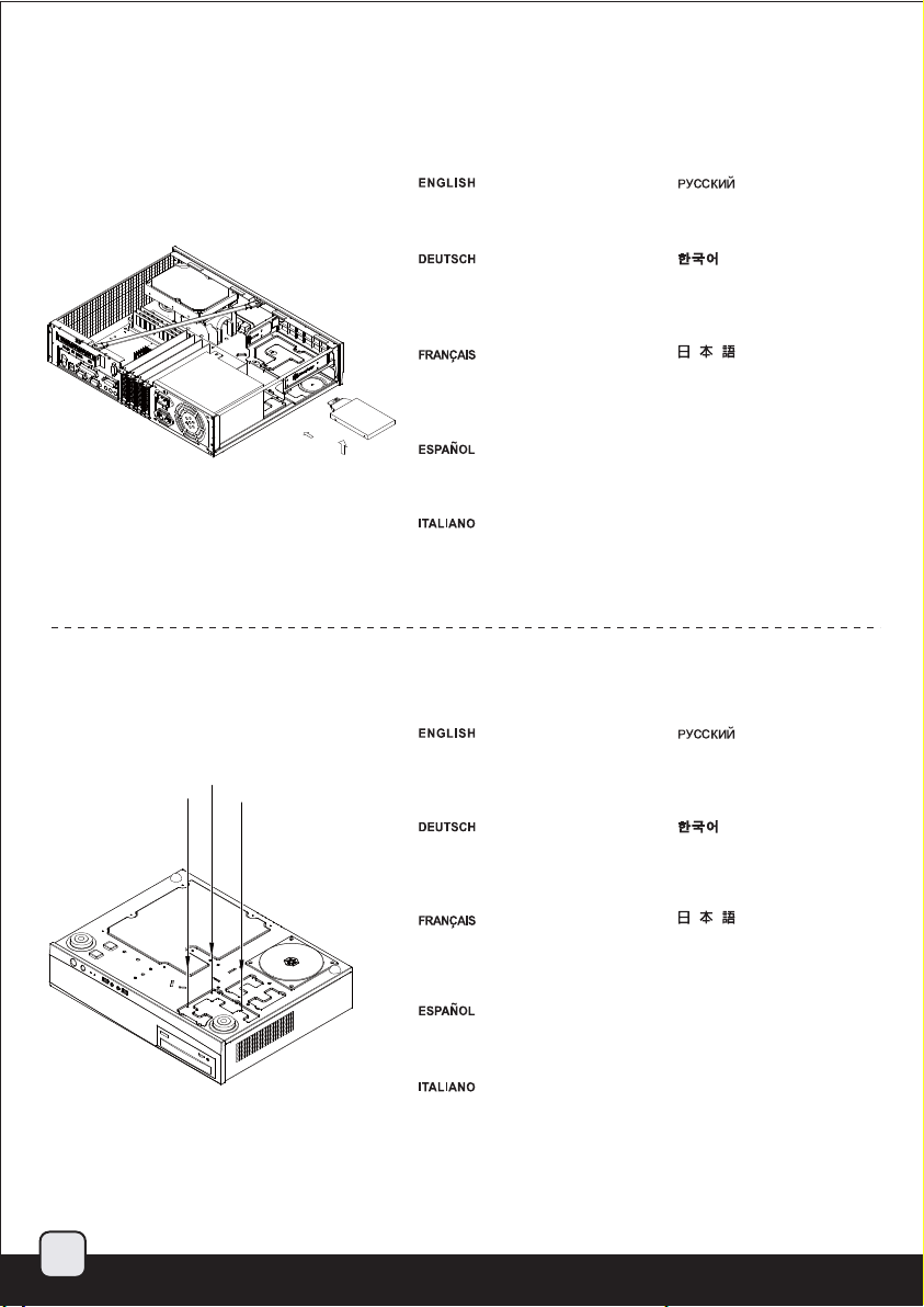
Insert 3.5” and 2.5” hard drives or
SSD as required from the left side
of the case and secure with screws.
Installieren Sie die 3,5 Zoll- bzw. 2,5
Zoll-HDDs/-SSDs von der linken Seite
des Gehäuses; befestigen Sie sie mit
Schrauben.
하드 드라이브 브라켓을 케이스에
재설치합니다. 이때 아래쪽의
케이블과 선을 주의 합니다.
ケースにハードドライブブラケット
を戻しますが、下部のケーブルと結
線に注意します。
繁体中文
將硬碟架裝回機殼,請注意下方的線材。Reinstale el bracket para discos duros
简体中文
将硬盘架装回机壳,请注意下方的线材。
Вставьте жесткие диски 3,5 и 2,5
дюйма или SSD с левой стороны
корпуса и закрепите винтами.
3.5" 및 2.5" 하드 드라이브 혹은 SSD
필요한 만큼 삽입한 후, 케이스 왼쪽에
나사로 고정시킵니다.
를
Insérez les disques dur 3.5” et 2.5”
ou SSD selon vos besoin par le côté
gauche et fixez les avec des vis.
Inserte los discos duros de 3,5” ó
2,5” ó SSD según sea necesario
en el lado izquierdo de la carcasa
y fíjelos con tornillos.
Inserire gli hard drive da 3,5” o
2,5” dalla parte sinistra del case
ed assicurarli con le viti.
ケース左側から必要とされる3.5イン
チと2.5インチのハードドライブまた
はSSDを入れ、ネジで固定します。
繁体中文
將3.5"硬碟與2.5"硬碟由左方插入機殼,
並以螺絲鎖固。
简体中文
将3.5"硬盘与2.5"硬盘由左方插入机壳,
并以螺丝锁固。
10
Page 12

12.
简体 中文
繁体 中文
简体 中文
繁体 中文
A
13.
Please remove 5.25” drive bay cover
and insert the optical drive from the
front into the case.
Bitte entfernen Sie die Abdeckung
des 5,25 Zoll-Einschubs; stecken
Sie das optische Laufwerk von vorne
in das Gehäuse.
Veuillez retirer le cache de la baie
5.25” et insérez le lecteur optique
par l'avant du boîtier.
Por favor, quite la cubierta para la
bahía de dispositivos de 5,25” e
inserte el dispositivo óptico por la
parte frontal de la carcasa.
Rimuover il cover del bay da 5,25” ed
installare il drive ottico inserendolo nel
case dalla parte frontale.
Connect the cables required by the
optical drive then push it into the case
further until it lines up with the front panel.
Due to limited space, please secure with
thumb screws.
Schließen Sie das optische Laufwerks
an; schieben Sie es dann tiefer in das
Gehäuse hinein, bis es bündig mit der
Frontblende abschließt. Befestigen Sie
es mit Schrauben. Aus Platzgründen mit
Rändelschrauben fixieren.
Снимите крышку отсека дисковода 5,25
дюймов и вставьте оптический дисковод
с передней стороны корпуса.
5.25” 드라이브 베이 커버를 제거한 후,
광드라이브를 케이스 전면으로 부터
삽입합니다.
5.25インチのドライブベイカバーを取
り外し、光学ドライブを正面からのケ
ースに入れます。
繁体中文
移除光碟機檔板,
將光碟機由前方插入機殼。
简体中文
移除光驱文件板,
将光驱由前方插入机壳。
Подсоедините кабели оптического
дисковода и вставьте его в корпус таким
образом, чтобы он совпадал с передней
панелью. Закрепите винтами. Из за
ограниченного пространства их
необходимо закрепить винтами.
광드라이브에 필요한 케이블을 연결하고,
케이스에 밀어 넣어 전면 패널과 정렬되도록
맞춘 후 나사로 고정합니다. 공간의 제약이
있을 수 있으니 손나사로 고정 하시기
바랍니다.
11
Branchez les câbles du lecteur optique
et poussez le à l'intérieur du boîtier afin
de l'aligner avec la façade du boîtier.
Fixez le avec des vis. A cause de l'espace
limité, veuillez le fixer avec des vis à main.
Conecte los cables que precise el dispositivo
óptico y luego empújelo hacia el fondo
de la carcasa hasta que se alinee con el
A
panel frontal. Fíjelo con tornillos. Debido
al espacio limitado, por favor use tornillos
manuales.
Connettere i cavi necessari al drive ottico,
quindi allinearlo al frontale del case, a questo
punto serratelo alla struttura con le viti.
A causa dello spazio limitato, si prega di
utilizzare le viti fornite a corredo.
光学ドライブに必要とされるケーブルを
接続し、フロントパネルの面に合うまで、
ケースに押し込みます。 ネジで固定しま
す。スペースが限られるので、サムスク
リューで固定します。
繁体中文
先將光碟機連接線接上,之後才將光碟機推
至與前面板齊平。由於空間限制,請使用
內附的手鎖螺絲。
简体中文
先将光驱连接线接上,之后才将光驱推至与
前面板齐平。由于空间限制,请使用内附
的手锁螺丝。
Page 13

14.
简体 中文
繁体 中文
简体 中文
繁体 中文
Reinstall center brace back into the case. Установите центральную скобу
обратно в корпус.
15.
Bringen Sie die mittlere Verstärkung
wieder im Gehäuse an.
Réinstallez la barre centrale dans
le boîtier.
Reinstallare il sostegno centrale nel case.
Place the top cover back onto the
case and secure with three screws
to complete installation.
Platzieren Sie die obere Abdeckung
auf dem Gehäuse und befestigen Sie
sie zum Abschluss der Installation
mit drei Schrauben.
중심 브레이스를 케이스에 재
설치합니다.
ケースにセンターブレースを戻
します。
繁体中文
將中央支撐架裝回機殼。Reinstale el soporte central en la carcasa.
简体中文
将中央支撑架装回机壳。
Завершите установку, установив
верхнюю крышку обратно на корпус
и закрепив тремя винтами.
상부 커버를 케이스에 재 장착후 3개의
나사로 고정시켜 설치를 마칩니다.
Remettez le panneau supérieur sur le
boîtier et fixez le avec trois vis pour
terminer l'installation.
la carcasa y fíjela con tres tornillos para
completar la instalación.
Riposizionare quindi il cover superiore
ed assicurarlo allo chassis con le tre viti
rimosse in precedenza per completare
l’installazione.
ケースに上部カバーを戻し、3つのネ
ジ3本で固定すると、インストールは
完成です。
繁体中文
將上蓋裝回機殼,完成組裝。Vuelva a poner la cubierta superior en
简体中文
将上盖装回机壳,完成组装。
12
Page 14

Connector definition
(1) Front panel connector installation
Power switch and reset switch installation guide:
Please refer to the motherboard manuals for the motherboard’s “Front Panel Connector” or “System Panel Connector” pin definition.
Power switch and reset switch have no polarity, so they can be connected in any orientation.
Ein-/Ausschalter und Rücksetztaste (Reset) installieren:
Bitte suchen Sie in der Motherboard-Dokumentation nach der Pinbelegung der Anschlüsse des Frontbedienfeldes („Front Panel Connectors“
oder „System Panel Connectors“). Ein-/Austaste und Rücksetztaste benötigen keine bestimmte Polarität, können daher beliebig (ohne auf +
und - zu achten) angeschlossen werden.
Guide d'installation des interrupteurs d'allumage et de réinitialisation :
Veuillez-vous référer au manuel de votre carte mère pour la description des broches "des connecteurs du panneau frontal" et des broches "des
connecteurs du panneau système". Les interrupteurs d'allumage et de réinitialisation ne possède pas de polarité, donc ils peuvent être branché
dans les deux sens.
Guía de instalación de los interruptores de encendido y reseteo:
Por favor, consulte en los manuales de la placa base la configuración de pines del “Conector de panel frontal” ó “Conector de panel de sistema”
de su placa base. Los interruptores de encendido y reseteo no tienen polaridad, luego se pueden conectar con cualquier orientación.
Guida all’installazione dei connettori Power Switch e Reset Switch:
Fare riferimento al manuale della scheda madre nella sezione “Connettori del pannello frontale” o “Connettori del pannello di sistema”.
Power switch e reset switch non hanno polarità, posso essere pertanto connessi con qualsiasi orientamento.
Инструкция по подключению выключателя питания и кнопки перезагрузки (reset):
Описание контактов разъемов приведены в разделах “Разъ емы передней панели” или “Разъемы системной панели” руководства
пользователя материнской платы. Выключатель питания и кнопка перезагрузки не имеют полярности, поэтому их можно подключать
в любой ориентации.
파워 스위치 및 리셋 스위치 설치 가이드
메인보드 매뉴얼의 전면패널 커넥터 혹은 시스템패널 커넥터 핀을 참조하기 바랍니다. 파워 스위치와 리셋 스위치는 극성이 없어
어떤 방향으로 설치해도 무방합니다.
電源スイッチおよびリセットスイッチのインストールガイド:
マザーボードの「フロントパネルコネクタ」または「システムパネルコネクタ」のピン配列についてはマザーボードマニュアルを参照
してください。電源スイッチとリセットスイッチに極性はないので、いずれの方向でも接続できま。
Power Switch 與Reset Switch安裝說明:
請參考主機說明書的Front Panel Connectors安裝Pin Define,將Connector插上;Power Switch 與Reset Switch並無正負極性之分,
反插正插都不影響功能性。
Power Switch 与Reset Switch安装说明:
请参考主机说明书的Front Panel Connectors 安装Pin Define,将Connector插上;Power Switch与Reset Switch并无正负极性之分,
反插正插都不影响功能性。
13
Page 15
Connector definition
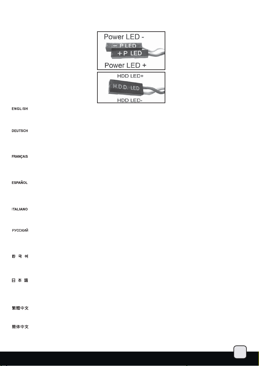
LED connector installation guide:
Please refer to the motherboard manuals for the motherboard’s “Front Panel Connector” or “System Panel Connector” pin definition.;
the white wires are negative while other colors are positive wires. The Power LED wires are separate pins for compatibility with different
motherboard pin definition so please make sure they are connected in the right polarity by referring to your motherboard manual.
LED-Verbinder installieren:
Bitte suchen Sie in der Motherboard-Dokumentation nach der Pinbelegung der Anschlüsse des Frontbedienfeldes („Front Panel Connectors“
oder „System Panel Connectors“). Die weißen Adern sind negativ (-), die farbigen Adern positiv (+).Die Kabel für die Betriebsanzeige-LED
sind zur Kompatibilität mit unterschiedlichsten Motherboards einzeln, nicht als kompletter Stecker ausgeführt. Achten Sie hier bitte auf die
richtige Polarität, lesen Sie in der Dokumentation Ihres Motherboards nach.
Guide d'installation du connecteur LED :
Veuillez-vous référer au manuel de votre carte mère pour la description des broches "des connecteurs du panneau frontal" et des broches "
des connecteurs du panneau système". Les câbles colorés en blanc sont négatifs alors que ceux d'une autre couleur sont positifs.Les câbles
de la LED Power sont séparés afin d'être compatible avec différentes cartes mères, donc vérifiez bien qu'ils sont branchés avec la bonne
polarité en vous référant au manuel de votre carte mère.
Guía de instalación del conector LED:
Por favor, consulte en los manuales de la placa base la configuración de pines del “Conector de panel frontal” ó “Conector de panel de sistema”
de su placa base. Los cables de color blanco son negativos mientras que los de color son positivos. Los cables LED de potencia tienen pines
separados para compatibilidad con diferentes definiciones de pines de la placa base luego por favor, asegúrese de que están conectados en la
polaridad correcta consultando el manual de su placa base.
Guida all’installazione del connettore LED:
Fare riferimento al manuale della scheda madre nella sezione “Connettori del pannello frontale” o “Connettori del pannello di sistema”. I cavi
di colore bianco sono il polo negativo, mentre quelli di colore diverso il positivo.Guida all’installazione del Power Led serie RV/KLConnettere
direttamente il connettore ad un molex dell’alimentatore.
Инструкция по подключению коннектора для светодиодного индикатора питания:
Описание контактов разъемов приведены в разделах “Разъемы передней панели” или “Разъемы системной панели” руководства
пользователя материнской платы. Белые провода - отрицательной полярности, цветные провода - положительной полярности.
Провода светодиодного индикатора питания имеют отдельные контакты для совместимости с различными типами контактов
материнских плат, поэтому обратитесь к руководству пользователя материнской платы и убедитесь, что полярность соблюдена.
LED 커넥터 설치 가이드
메인보드 매뉴얼의 전면패널 커넥터 혹은 시스템패널 커넥터 핀을 참조하기 바랍니다. 하얀선의 경우 음극이며, 다른 색의 경우
양극입니다. 파워 LED 선은 분리되어 다양한 메인보드에서 동작할 수 있도록 되어 있습니다. 그러므로 메인보드 매뉴얼을 참조하여
올바를 극성을 주의해 선택하시기 바랍니다.
LEDコネクタのインストールガイド:
マザーボードの「フロントパネルコネクタ」または「システムパネルコネクタ」ピン配列についてはマザーボードマニュアルを参照
してください。白色のリード線はマイナスで、色の着いたリード線がプラスです。電源LEDリード線は種々のマザーボードピン定義と
互換性を持たせるため分離されたピンとなっているので、ご使用のマザーボードマニュアルを参照して、 適切な極性に接続されるよ
うお確かめください。
LED接頭安裝說明:
請參考說明書的Front Panel Connectors安裝Pin Define,將Connector插上;白色線的部分為負極,彩色線的部分是正極。
Power LED為了適應各主機板的不同,特別設計為散Pin樣式,請安心使用。
LED接口安装说明:
请参考说明书的Front Panel Connectors安装Pin Define,将Connector插上;白色线的部份为负极, 彩色线的部份为正极。
Power LED为了适应主机板的不同,特别设计为散Pin样式,请安心使用。
14
Page 16

Front I/O connector guide
Below are the front I/O connectors pin definition, please also check your motherboard manual to cross reference with motherboard’s
front I/O pin headers. SilverStone’s I/O connectors are in block type to simplify installation.
Nachstehend finden Sie die Pinbelegung der vorderen E/A-Anschlüsse; bitte gleichen Sie zudem das Handbuch Ihres Motherboards mit
den vorderen E/A-Pinzuweisungen ab. SilverStones E/A-Anschlüsse befinden sich zur Vereinfachung der Installation in Blockart.
Au dessous de la description des broches des ports d'E/S, veuillez aussi vérifier sur le manuel de votre carte mère de manière croisée
que les broches sont correctement placées. Les connecteurs d'E/S de SilverStone sont en bloc pour en simplifier leur installation.
A continuación se detallan los pines para conectores E/S frontales, compruebe también por favor el manual de su placa base para
cotejar los pines E/S frontales de la misma. Los conectores E/S de SilverStone son del tipo bloque para simplificar la instalación.
Ниже приведено описание контактов передних разъемов ввода/вывода. Обратитесь также к руководству пользователя материнской
платы за описанием передних разъемов ввода/вывода типа "пин-хедер". Разъемы ввода/вывода "SilverStone" - бл очного типа, что
облегчает сборку.
Di seguito lo schema delle connessioni I/O frontali, confrontare lo schema con quanto riportato sul manuale della scheda madre per
effettuare un controllo incrociato. I connettori I/O Silverstone, per semplificare l’installazione, sono del tipo “a blocco”.
아래는 전면 I/O 커넥터의 핀 사양입니다. 메인보드 매뉴얼을 참조해, 메인보드의 전면 I/O 핀사양을 재 확인한 후 설치합니다.
SilverStone의 I/O 커넥터는 블록 타입으로 구성되어 있어 간편한 설치가 가능합니다.
以下はフロントI/Oコネクタピン配列ですが、お持ちのマザーボードのフロントI/Oピンヘッダは、マザーボードマニュアルをご参照
ください。シルバーストーンのI/Oコネクタは、インストールの容易なブロックタイプになっています。
下表為Front I/O Connectors的Pin Define,請參閱主機板說明書的各Front I/O Connectors Pin Define一一核對。
ML03的Front I/O Connectors完全採用集合
下表为Front I/O Connectors的Pin Define,请参阅主机板说明书的各Front I/O Connectors Pin Define一一核对。
ML03的Front I/O Connectors完全采用集合Pin方式以简化安装。
Pin方式以簡化安裝。
USB 3.0 CONNECTOR
ID INTA_P2_D+
INTA_P1_D+
INTA_P1_D-
GND
INTA_P1_SSTX+
INTA_P1_SSTX-
GND
INTA_P1_SSRX+
INTA_P1_SSRX-
VBUS
HD AUDIO CONNECTOR
AUD GND PORTIL
PRESENCE
SENSE1_RETURN
SENSE2_RETURN
PIN
PORT1R
PORT2R
SENSE_SEND
PORT2R
INTA_P2_D-
GND
INTA_P2_SSTX+
INTA_P2_SSTX-
GND
INTA_P2_SSRX+
INTA_P2_SSRX-
VBUS
PIN
15
Page 17

Component size limitations
The ML03 was designed to be as small as possible while maximizing interior space usage, please refer to the
following guidelines forcomponent selection and future upgrade considerations.
(1) CPU cooler height limitation
The ML03 has 70mm height limitation for CPU cooler. The center brace is designed for structural reinforcement to support monitor
placement on top of the case. If you are not going to be placing anything on top of ML03 and the CPU cooler interferes with the
center brace, it is safe to remove it.
Das ML03 nimmt CPU-Kühler mit einer Maximalhöhe von 70 mm auf. Die mittlere Stütze dient der Strukturverstärkung, falls Sie beispielsweise
einen Bildschirm auf dem Gehäuse platzieren möchten. Falls Sie nichts auf dem ML03 platzieren möchten, können Sie die mittlere Verstärkung
selbstverständlich entfernen und so mehr Platz für den CPU-Kühler schaffen.
Le ML03 peut accueillir des dissipateurs de processeur d'une hauteur maximale de 70mm. La barre centrale est conçu pour renforcé la structure
afin de pouvoir placer un moniteur sur le boîtier. Si vous n'avez pas l'intention d'en placer un sur le ML03 et que votre dissipateur de processeur
est gêné par elle, vous pouvez le retirer.
La ML03 tiene una limitación de altura de 70mm para el disipador de la CPU. El soporte central está diseñado como refuerzo estructural y así
poder soportar un monitor situado sobre la carcasa. Si no va a poner nada sobre la ML03 y el disipador de la CPU interfiere con el soporte central,
puede retirarlo.
All’interno di ML03 possono essere installati dissipatori per CPU con altezza massima di 70mm. Il sostegno centrale è stato realizzato come
rinforzo nel caso si voglia disporre un monitor al di sopra del case. Se non avete intenzione di porre alcunché al di sopra dello chassis o se il
dissipatore CPU dovesse interferire con il sostegno, potete rimuoverlo.
Ограничением высоты охладителя ЦП в ML03 является значение 70 мм. Центральная скоба предназначена для усиления конструкции,
обеспечения опоры для размещения монитора с верхней части корпуса. Если сверху ML03 не планируется устанавливать какие-либо
устройства или охладитель ЦП мешает установке центральной
ML03은 CPU 쿨러의 높이 제한이 70mm입니다. 중심 브레이스는 구조적인 보강을 위한 것으로 모니터를 케이스에 올려 놓을때 지탱할 수
있도록 염두해 두었습니다. CPU쿨러를 중심 브레이스 방해할때 ML03에 아무것도 올려 놓지 않을 예정이라면, 중심 브레이스를 제거해도
무방합니다.
скобы, для обеспечения безопасности следует ее снять.
ML03ではCPUクーラーに70mmの高さ制限があります。センターブレースは、ケース上にモニタを設置できるよう構造を強化すべく設計さ
れています。ML03の上に何も置かないのであれば、CPUクーラーがセンターブレースで妨げられる場合、それを取り除いても安全です。
ML03 CPU Cooler限高為70mm。中支架的作用僅在機器上疊螢幕時做為補強作用;如果中支架與CPU Cooler干涉,您可以斟酌移除它。
ML03 CPU Cooler限高为70mm。中支架的作用仅在机器上迭屏幕时做为补强作用;如果中支架与CPU Cooler干涉,您可以斟酌移除它。
CPU cooler height limitation 70mm
Top Cover
70
Cooler
Motherboard
16
Page 18

(2) Power supply limitations
A: Depth limitation
The ML03 supports power supply with depth of up to 140mm. Power supplies with modular cables may have connectors that protrude out
too much and interfere with the optical drive installation. If you must use a modular power supply, please choose the optional SilverStone
TS03 slim optical drive adapter for installing a slim optical drive.
B: Cable length recommendations
Below is a table of recommend cable length based off of common retail power supplies. Please make sure that the power supply you want
to use has long enough cables to fit the below recommendations or you can also choose to purchase additional power cable extensions.
The table shows the length recommended for a power supply with cables coming out from the right side of the power supply casing (with the
power supply’s 120mm fan facing down)
A: Maximaltiefe
Das ML03 unterstützt Netzteile mit einer Maximaltiefe von 140 mm. Netzteile mit modularen Kabeln haben möglicherweise zu weit abstehende
Anschlüsse, die bei der Installation des optischen Laufwerks stören können. Wenn Sie ein modulares Netzteil nutzen möchten, verwenden Sie
bei der Installation eines schmalen Laufwerks bitte den optionalen Adapter TS03 von SilverStone.
B: Empfohlene Kabellänge
Nachstehend finden Sie eine Tabelle der empfohlenen Kabellänge basierend auf handelsüblichen Netzteilen. Bitte stellen Sie sicher, dass das
von Ihnen gewählte Netzteil entsprechend der nachstehenden Empfehlungen über ausreichend lange Kabel verfügt; alternativ können Sie
zusätzliche Netzkabelverlängerungen kaufen. Die Tabelle zeigt die empfohlene Länge bei einem Netzteil mit Kabeln, die aus der rechten Seite
des Netzteilgehäuses herauskommen (der 120 mm-Lüfter des Netzteils zeigt nach unten)
A: Profondeur
Le ML03 est compatible avec les alimentations ayant une profondeur jusqu'à 140mm. Les alimentation à câblage modulaire peuvent avoir
des connecteurs qui dépassent beaucoup et ainsi empêcher l'installation du lecteur optique. Si vous devez utiliser une alimentation modulaire,
choisissez l'adaptateur SilverStone TS03 pour lecteur optique slim et utilisez en un.
B: Longueur des câbles
Vous avez ci dessous un tableau avec la longueur des câbles recommandés basé sur les alimentations du marché. Veuillez bien vérifier que
l'alimentation que vous allez utiliser possède bien des câbles assez long pour être compatible avec ces recommandations. Sinon vous pouvez
choisir d'acheter des rallonges. Le tableau montre la longueur des câbles recommandées pour une alimentation qui a les câbles sortant du côté
droit du boîtier (avec le ventilateur de 120mm vers le bas)
A: Limitación de profundidad
La ML03 acepta fuentes de alimentación con una profundidad de hasta 140mm. Las fuentes de alimentación con cables modulares podrían tener
conectores que sobresalieran demasiado e interfirieran con la instalación del dispositivo óptico. Si debe usar una fuente de alimentación modular,
por favor escoja el adaptador opcional para dispositivo óptico TS03 de Silverstone para poder instalar un dispositivo óptico delgado.
B: Recomendaciones para la longitud del cable
A continuación hay una tabla con la longitud recomendada de los cables basada en fuentes de alimentación comunes. Por favor, asegúrese de
que la fuente de alimentación que quiere usar tiene cables lo bastante largos como para adecuarse a las recomendaciones siguientes, en caso
contrario puede decidir comprar extensiones adicionales para cables de potencia. La tabla muestra la longitud recomendada para una fuente de
alimentación con cables que salgan del lado derecho de la carcasa de la fuente de alimentación (con el ventilador de 120mm de la fuente de
alimentación hacia abajo)
A: Limitazione di profondità
ML03 supporta alimentatori con profondità massima di 140mm. Gli alimentatori modulari potrebbero avere connettori troppo sporgenti,
che possono interferire con il montaggio del drive ottico. Qualora vogliate adottare un alimentatore modulare, vi consigliamo di acquistare
l’adattatore SilverStone TS03, che rende possibile l’installazione di un drive ottico di tipo slim.
B: Misure dei cavi raccomandate
La tabella di seguito mostra le lunghezze dei cavi raccomandate e si basa sulle misure dei cavi con riferimento ai comuni alimentatori retail.
Assicuratevi che l’alimentatore che avete intenzione di utilizzare risponda alle caratteristiche richieste, altrimenti considerate l’acquisto di un
kit di prolunga cavi. La tabella mostra le misure consigliate prendendo in considerazione un alimentatore con le connessioni situate sulla parte
destra dello chassis ( con la ventola da 120mm rivolta verso il basso)
A: ограничение по глубине
ML03 поддерживает источники питания с глубиной не более 140 мм. Источники питания с модульными кабелями могут иметь
которые сильно выступают и мешают установке оптического дисковода. При необходимости использования модульного источника
питания используйте дополнительный переходник SilverStone TS03 для установки тонкого оптического дисковода.
B: рекомендации по длине кабелей
В следующей таблице представлены рекомендованные значения длины кабелей на основе значений имеющихся в продаже источников
питания. Убедитесь , что длина кабелей источника питания достаточна
можно приобрести дополнительные удлинители кабеля источника питания. В таблице указаны рекомендованные значения длины кабелей
источника питания при условии, что кабели выходят из правой стороны корпуса источника питания (вентилятор 120 мм источника питания
направлен вниз)
и соответствует следующим рекомендациям, в противном случае
разъемы,
17
Page 19

깊이 제한
ML03은 140mm 깊이까지의 파워 서플라이를 지원합니다. 모듈라 케이블을 갖고 있는 파워 서플라이는 커넥터가 돌출되어 광드라이브
설치에 방해가 될 수 있습니다. 모듈라 파워 서플라이를 사용할 경우 SilverStone
슬림 광드라이브 설치를 권장합니다.
추천 케이블 길이
아래 표에서는 일반적으로 판매되는 파워 서플라이의 추천 케이블 길이를 표시해 놓았습니다. 사용하고자 하는 파워 서플라이가 아래의
추천길에에 충분한 케이블을 갖추고 있는지 확인하시기 바라며, 필요시에는 추가의 연장 파워 케이블 구입이 가능합니다. 아래 표는 파워
서플라이의 오른쪽에서 나오는
A: 奥行き制限
ML03は最大奥行き140mmの電源をサポートします。モジュラーケーブル装備の電源は、コネクタが突出していて、光学ドライブのインストー
ルの妨げになる可能性があります。モジュラー電源を使う必要のある場合は、スリム光学ドライブのインストールに対応した、オプション装
備のシルバーストーンTS03スリム光学ドライブアダプタをお選びください。
B: 推奨ケーブル長さ
下記は、一般の小売り電源の推奨ケーブル長さの表です。使いたい電源が下記の推奨基準に合った、十分の長さのケーブルを持っていること
を確認してください。または電源用の延長ケーブルを購入することもできます。表では、推奨ケーブル長は電源ケースの右側(電源の120mmフ
ァンは下向き)から出ているケーブルの長さが示されています。
A:長度限制
ML03支援長度最長至140mm的電源供應器。模組化電源供應器因為接頭可能會與光碟機干涉,可能不能安裝,如果您必須使用模組化的電源供應器,
請選用TS03薄型光碟機轉換架。
B:電源線材建議長度
以下是以一般市售主機板與電源抓出來的各線材建議長度列表,請先確認電源線長度是否足夠,如果不夠請選購所需要的延長線。本表是以電源出
線端在右方的電源(此時120mm風扇應當朝下)為假設條件。
A:长度限制
ML03支持长度最长至140mm的电源供应器。模块化电源供应器因为接头可能会与光驱干涉,可能不能安装,如果您必须使用模块化的电源供应器,
请选用TS03薄型光驱转换架。
B:电源线材建议长度
以下是以一般市售主机板与电源抓出来的各线材建议长度列表,请先确认电源线长度是否足够,如果不够请选购所需要的延长线。本表是以电源
出线端在右方的电源(此时120mm风扇应当朝下)为假设条件。
케이블의 길이를 나타낸것입니다. (이 경우 파워 서플라이의 120mm 팬은 아래를 향합니다. )
의 TS03 과 같은 슬림 광드라이브 어댑터를 이용해
Power supply length limitation 140mm
PSU
Cable type and location
EPS 8pin/ATX4pin (over the motherboard)
ATX 24Pin (over the motherboard)
ATX 24Pin (under the right hard drive cage)
SATA 15Pin to optical drive
SATA 15Pin to 2.5” drive
SATA 15Pin to left lower 3.5” drive
SATA 15Pin to right front 3.5” drive
Minimum length
400mm
250mm
300mm
50mm
75mm
150mm
250mm
18
Page 20
(3) Graphics card/expansion card length limitation
223mm
SATA CONNECTOR
With 3.5” SATA hard drive installed on the right front, the ML03 can accommodate low profile expansion cards up to 8.78” long.
Standard low profile cards usually are only 6.6” long so the ML03 should fit nearly all types of low profile cards.
Wenn eine 3,5 Zoll-SATA-Festplatte im vorderen rechten Bereich installiert ist, kann das ML03 Low-Profile-Erweiterungskarten mit einer Länge
von bis zu 22,3 cm aufnehmen.
Standard-Low-Profile-Karten sind üblicherweise nur 16,76 cm lang - dadurch passen nahezu alle Arten von Low-Profile-Karten in das ML03.
Avec le disque dur 3.5” SATA installé à l'avant et à droite, le ML03 peut accueillir des carte d'extension low profile jusqu'à 8.78” de long.
Les cartes low profile standard ont habituellement une longueur de seulement 6.6” long donc le ML03 pourra accueillir tous les types de
cartes low profile.
Con el disco duro SATA de 3,5” instalado en la parte delantera derecha, la ML03 puede acomodar tarjetas de expansión de perfil bajo de hasta
8,78” de longitud.
Las tarjetas normales de perfil bajo suelen tener solo 6,6” de longitud, luego la ML03 debería poder instalar cualquiera de estas tarjetas.
Если диск 3,5 дюйма SATA установлен с правой передней стороны, в ML03 можно установить платы расширения малых размеров
длиной до 8,78 дюймов.
Стандартные платы малого размера обычно имеют длину 6,6 дюйма, поэтому ML03 должен поддерживать практически все типы
плат малого размера.
Con hard disk SATA da 3,5” installato frontalmente sulla destra, ML03 può alloggiare schede di espansione a basso profilo lunghe fino a 223mm.
Le schede low profile standard sono generalmente lunghe soltanto 167,6mm quindi, all’interno di ML03, possono essere installate quasi tutte le
schede low profile.
3.5” SATA 하드 드라이브가 전면 오른쪽에 설치된 상태에서, ML03은 8.78”까지 LP 형태의 확장 카드를 지원합니다.
일반적인 LP 카드의 경우 대부분 6.6” 의 길이를 갖고 있어 ML03은 거의
3.5インチSATA ハードドライブを右前にインストールした状態で、ML03は長さ最大8.78インチのロープロファイル拡張カードを装着できます。
標準のロープロファイル拡張カードは通常、長さ6.6インチに過ぎないので、ML03にはほとんど全てのタイプのロープロファイルカードが搭載
可能です。
以右前方有安裝3.5”SATA硬碟之下ML03 支援最長8.78”長的Low profile介面卡。
請注意一般規範的Low profile介面卡長度只有6.6”,所以任何的Low profile介面卡應當都可以安裝。
以右前方有安装3.5”SATA硬盘之下ML03 支持最长8.78”长的Low profile适配卡。
请注意一般规范的Low profile适配卡长度只有6.6”,所以任何的Low profile适配卡应当都可以安装。
대부분의 LP 카드 장착이 가능합니다.
19
Page 21

(4) Optical drive length limitation
Optical drive lenght limitation: 170mm
140 170
29.0
ML03 is shorter in depth than average cases, the total allowable length with optical drive and the power supply plus cables combined is 339mm.
When using standard depth 140mm power supply, we recommend the maximum length for optical drive to be 170mm with 90 degrees angled
SATA data and power cables. If you need to use longer optical drive or install hard drive racks into the 5.25” drive bay, we recommend using
shorter power supplies:
Das ML03 hat eine geringere Tiefe als Durchschnittsgehäuse; die erlaubte Gesamtlänge von optischem Laufwerk und Netzteil plus Kabeln
beträgt 339 mm. Wenn Sie Netzteile mit einer Standardtiefe von 140 mm verwenden, empfehlen wir eine Maximallänge des optischen
Laufwerks von 170 mm mit um 90 Grad angewinkelten SATA-Daten- und -Netzkabeln. Wenn Sie ein längeres optisches Laufwerk einsetzen
bzw. Festplatten-Racks im 5,25 Zoll-Einschub installieren möchten, empfehlen wir die Verwendung eines kürzeren Netzteils:
Le ML03 a une profondeur plus réduite que la plupart des boîtiers, la longueur totale combinée du lecteur optique et de l'alimentation ne doit
pas excéder 339mm. Lorsque vous utilisez une alimentation de profondeur standard de 140mm, nous vous recommandons d'utiliser un lecteur
optique ayant une longueur maximale de 170mm et d'utiliser un connecteur SATA et un connecteur d'alimentation ayant un angle de 90 degrés.
Si vous devez utilisez un lecteur optique plus long ou installer un rack pour disque dur dans la baie 5.25”, nous vous recommandons d'utiliser
une alimentation moins profonde:
La ML03 es menos profunda que una carcasa normal, la longitud total permitida con dispositivo óptico y fuente de alimentación más cables
combinados es de 339mm. Cuando se usa una fuente de alimentación de profundidad normal de 140mm, le recomendamos que la longitud
máxima del dispositivo óptico sea de 170mm con cables de datos SATA y de alimentación con ángulo de 90 grados. Si necesita usar dispositivos
ópticos de mayor longitud ó instalar un soporte para discos duros en la bahía para dispositivos de 5,25”, le recomendamos que use fuentes de
alimentación menos profundas:
CD-ROMPSU
ML03 имеет меньшую глубину, чем обычные корпусы, и общая длина с оптическим дисководом, источником питания и кабелями
составляет 339 мм. При использовании источника питания стандартной глубины 140 мм рекомендуется, чтобы максимальная длина
оптического дисковода
необходимости использования более длинного оптического дисковода или установки стоек жесткого диска в отсек 5,25 дюйма
рекомендуется использовать источники питания с меньшей длиной:
ML03 è meno profondo della media, la massima lunghezza totale consentita, con il drive ottico ed un alimentatore/cavi è di 339mm. Quando
viene utilizzato un alimentatore con profondità standard di 140mm vi raccomandiamo di utilizzare un drive ottico non più lungo di 170mm e
collegarlo per mezzo di cavi con connettori a 90°. Se doveste aver bisogno di installare nel bay da 5,25” drive o contenitori per hdd ottici più
lunghi, vi consigliamo di utilizzare alimentatori più corti.
ML03은 일반적인 케이스에 비해 깊이가 짧은데, 광드라이브 파워 서플라이 케이블 까지 339mm 의 깊이가 허용 가능합니다. 일반적인
140mm 깊이의 파워 서플라이를 사용할 경우 90도 SATA 케이블 사용시 광드라이브의 최대 길이가 170mm 까지 가능합니다. 만약 더
길이가 더 긴 광드라이브 및 하드 드라이브 랙을 5.25” 드라이브 베이에 장착하려 한다면 보다 짧은 파워 서플라이 사용을 권합니다.
составляла 170 мм с кабелями SATA и источником питания, установленным под углом 90 градусов. При
20
Page 22

ML03は一般のケースより奥行きが短く、光学ドライブと電源とケーブルを合わせた許容長さは339mmです。 標準の奥行き140mmの電源を使う
場合、90度アングルのSATAデータと電源ケーブルを併用して最大長さ170mmの光学ドライブを使用されるようお勧めします。より長い光学ド
ライブを使うか、5.25インチドライブベイにハードドライブラックをインストールする必要があるならば、より奥行きの短い電源を使うよ
うにお勧めします。
ML03的長度較一般機殼短,光碟機與電源在加上中間線材接頭最大長度為339mm,在使用一般長度140mm的電源時,我們建議只使用長度170mm
最短的光碟機,並且在SATA的排線與電源線都使用90度規格的接頭。如果有需要使用更長的光碟機,或是硬碟抽取架時。
我們建議使用更短的電源:
ML03的长度较一般机壳短,光驱与电源在加上中间线材接头最大长度为339mm,在使用一般长度140mm的电源时,我们建议只使用长度170mm
最短的光驱,并且在SATA的排线与电源线都使用90度规格的接头。如果有需要使用更长的光驱,或是硬盘抽取架时。
我们建议使用更短的电源:
ATX PS/3 or SFX power supplies with ATX adapter bracket can be used as shorter replacements.
(5) Lower left 3.5” hard drive limitation
In order to facilitate cable connections, we designed the lower left cage to accept hard drive with connectors facing inwards. Unfortunately this
design is not applicable for IDE based hard drives as the much large ribbon cable will interfere with the motherboard. If you have IDE based
hard drive, please do not install in this location.
Zur Vereinfachung der Kabelanschlüsse können Sie die Festplatte im unteren linken Käfig so installieren, dass die Anschlüsse nach innen
zeigen. Leider ist dieses Design nicht mit IDE-basierten Festplatten kompatibel, da die wesentlich größeren Flachbandkabel im Hinblick auf
das Motherboard stören würden. Falls Sie IDE-Festplatten haben, installieren Sie sie bitte nicht in dieser Position.
Dans le but de faciliter le branchement des câbles, nous avons conçu et emplacement de telle sorte qu'il accepte le branchement de connecteur
par devant. Malheureusement il ne peut pas être utilisé avec des disques dur IDE car la nappe gênera avec la carte mère. Si vous avez des
disques dur IDE, veuillez ne pas utiliser cet emplacement.
Para facilitar las conexiones de los cables, diseñamos la carcasa inferior izquierda para aceptar el disco duro con conectores que vayan hacia
abajo. Por desgracia este diseño no es aplicable para discos duros IDE ya que el cable, mucho más ancho, interferiría con la placa base. Si tiene
un disco duro IDE, por favor no lo instale en este lugar.
21
Page 23
Для упрощения соединения кабелей нижний левый отсек разработан таким образом, что разъемы жесткого диска обращены вовнутрь.
简体 中文
繁体 中文
К сожалению, подобная конструкция исключает возможность использования жестких дисков IDE, поскольку большой плоский кабель
будет мешать материнской плате. При использовании жестких дисков IDE не устанавливайте их в корпус.
Al fine di facilitare la connessione dei cavi, abbiamo progettato il supporto in basso a sinistra in modo che connettori siano rivolti verso l’interno.
Sfortunatamente questa struttura non permette l’uso di hard disk IDE dal momento che il flat di connessione interferirebbe con la scheda madre.
Se possedete un hard disk IDE, non installatelo in questo alloggiamento.
케이블 연결을 유연하게 하기위해, 왼쪽 하부의 케이지가 하드 드라이브 커넥터를 안쪽에서 연결할 수 있도록 디자인 되어 있습니다.
안타깝게도 이런 디자인은 IDE 방식의 하드 드라이브는 더 큰 리본 케이블이 메인보트에 방해를 받아 사용이 가능하지 않을 수 있습니다.
만약 IDE 방시의 하드 드라이브를
ケーブル接続を容易にするために、内側に向かうコネクタを備えたハードドライブが左下のケージに装着できるよう設計しました。あいにくこ
の設計はIDEベースハードドライブのために適用可能でありません。それは多くの大型のリボン・ケーブルがマザーボードにとって邪魔になるか
らです。IDEベースのハードドライブをお持ちの場合は、この位置にインストールしないでください。
為了方便排線安插,我們特地將此顆硬碟轉橫向來安裝,但就是不能相容於IDE硬碟,電源線會與主機板干涉。如果你還有IDE硬碟,
請不要安裝在這個位置。
为了方便排线安插,我们特地将此颗硬盘转横向来安装,但就是不能兼容于IDE硬盘,电源线会与主机板干涉。如果你还有IDE硬盘,
请不要安装在这个位置。
장착하고자 한다면, 이 위치에 장착을 피하시기 바랍니다.
Upgrade and maintenance
(1) Multi-purpose drive cage design
5.25” drive cage
The 5.25” drive cage can also be used to install one 3.5” hard drive or two 2.5” drives, please refer to the below steps:
1.
Remove all six screws from the
optical drive cage to remove it.
Извлеките все шесть винтов
из держателя для оптического
дисковода, чтобы снять его.
Lösen Sie alle sechs Schrauben von
der Halterung des optischen Laufwerks,
nehmen Sie sie heraus.
Retirer les six vis du casier du lecteur
optique pour le retirer.
para dispositivos ópticos para quitarla.
Rimuovere le sei viti del supporto
per asportarlo.
광드라이브 케이지를 고정하고 있는
6개의 나사를 모두 제거합니다.
光学ドライブケージからネジ6本
全部を外して、ケージを取り外
します。
繁体中文
鬆開光碟架的6個螺絲,取下光碟架。Retire los seis tornillos de la carcasa
简体中文
松开光盘架的6个螺丝,取下光盘架。
22
Page 24
2.
简体 中文
繁体 中文
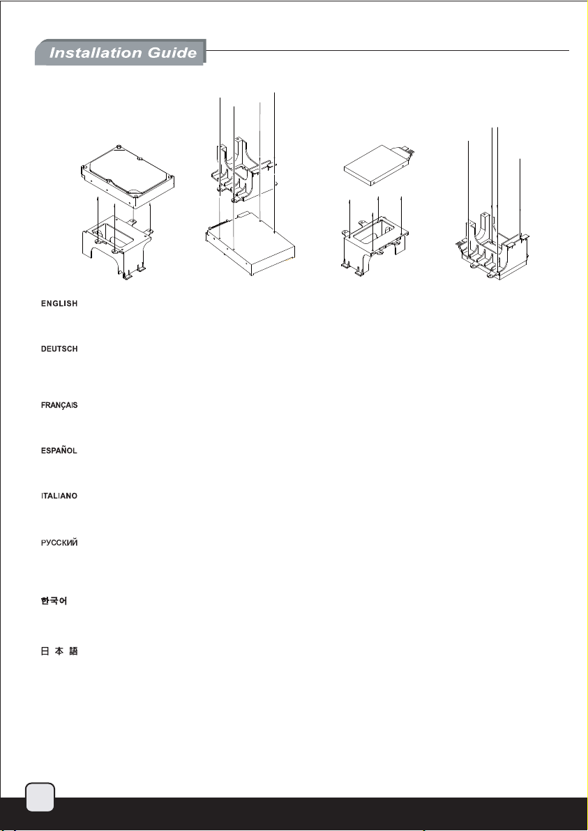
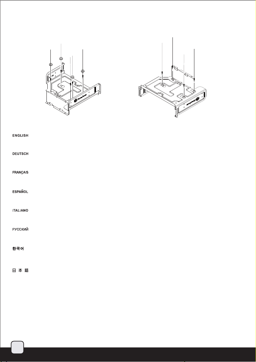
To install a 3.5” hard drive, insert the four rubber ring pads from the included accessories box into the pre-drilled holes for the 3.5” hard drive
mounts then secure the hard drive with four hard drive screws from the bottom.
Stecken Sie zur Installation einer 3,5 Zoll-Festplatte die vier mitgelieferten ringförmigen Gummipuffer in die vorgebohrten Löcher der 3,5 ZollFestplattenhalterung; befestigen Sie die Festplatte dann mit vier Schrauben von der Unterseite.
Pour installer un disque dur 3.5”, insérez les quatre anneaux en caoutchouc de la boîte d'accessoires dans les trous pré-percés pour le
montage des disques durs 3.5” puis fixez-le avec quatre vis par le dessous.
Para instalar un disco duro de 3,5”, inserte los cuatro anillos de goma de la caja de accesorios en los agujeros de las monturas para discos
duros de 3,5” y luego fije el disco duro con cuatro tornillos desde abajo.
Per installare un hard disk da 3,5” inserire I Quattro pad in gomma forniti a corredo nei fori predisposti sul supporto. Utilizzare quindi quattro
viti per serrare dal basso l’hard disk al supporto.
Для установки жесткого диска 3,5 дюйма вставьте четыре резиновые кольцевые прокладки (находятся в коробке принадлежностей)
в специально просверленные отверстия для крепления жесткого диска 3,5 дюйма, затем закрепите жесткий диск четырьмя винтами снизу.
3.5” 하드 드라이브 설치를 위해 동봉된 악세사리에서 4개의 고무링
드라이브를 4개의 나사로 아래쪽으로 고정합니다.
3.5インチハードドライブをインストールするには、付属品ボックスからの4つのゴムリングパッドを3.5インチハードドライブマウント用
の既に開けられた穴に入れてから、底部からハードドライブネジ4本でハードドライブを固定します。
繁体中文
如果要安裝3.5”硬碟.請先塞入零件包中4個防震墊圈;將硬碟底部4個孔位鎖上防震螺絲。
简体中文
如果要安装3.5”硬盘.请先塞入零件包中4个防震垫圈;将硬盘底部4个孔位锁上防震螺丝。
패드를 미리 뚤려 있는 하드 드라이브 마운트에 장착한 뒤 하드
23
Page 25

3.
简体 中文
繁体 中文
To install 2.5” drives, secure them with screws from the bottom. Please note drive installed on the left side will only have three
mounting points.
Befestigen Sie 2,5 Zoll-Festplatten von der Unterseite mit Schrauben. Bitte beachten Sie, dass die auf der linken Seite installierte
Festplatte nur an drei Punkten montiert wird.
Pour installer des disques 2.5”, fixez les avec des vis par le dessous. Veuillez noter que le lecteur installer sur le côté gauche n'aura
que trois points de montage.
Para instalar dispositivos de 2,5”, fíjelos con tornillos desde abajo. Por favor, tenga en cuenta que el dispositivo instalado en el lado
izquierdo tendrá solo tres puntos de montura.
Per installare i drive da 2,5” assicurarli alla struttura con le viti serrandole dal basso. Vi segnaliamo che per il drive posto a sinistra
sono previsti soltanto tre punti di serraggio.
Для установки жесткого диска 2,5 дюйма закрепите его винтами снизу. Обратите внимание, что жесткий диск с левой стороны будет
иметь только три точки крепления.
2.5” 드라이브 장착을 위해 나사를 아래쪽에서 고정하는데, 왼쪽의 경우 나사 3개만 이용핸 고정시킬 수 있습니다.
2.5インチドライブをインストールするには、底部からネジによって固定します。左側にインストールされたドライブには設置箇所
が3つしかない点にご注意ください。
繁体中文
如果要安裝2.5”硬碟,請從底部鎖上螺絲;需注意左邊的2.5”硬碟只有3個螺絲孔位。
简体中文
如果要安装2.5”硬盘,请从底部锁上螺丝;需注意左边的2.5”硬盘只有3个螺丝孔位。
24
Page 26
简体 中文
繁体 中文
简体 中文
繁体 中文
Upgrade and maintenance
Lower left 3.5” drive cage
The lower left 3.5” drive cage is also compatible with one 2.5” drive installation
1.
2.
Insert the 2.5” drive into the lower left
side of the case.
Stecken Sie das 2,5 Zoll-Laufwerk
unten links in das Gehäuse.
Insérer le lecteur de 2.5” dans
l'emplacement inférieur gauche
du boîtier.
inferior izquierdo de la carcasa.
Inserire il drive da 2,5” dalla parte
bassa sinistra del case.
Line up with the three holes on the
bottom of the case and secure with
screws.
Вставьте жесткий диск 2,5 дюйма
в нижнюю левую часть корпуса.
2.5” 드라이브를 케이스의 왼쪽
하부에 삽입합니다.
2.5インチドライブをケースの
左下側に装着します。
繁体中文
將2.5”硬碟由左方塞入機殼。Inserte el dispositivo de 2,5” en el lado
简体中文
将2.5”硬盘由左方塞入机壳。
Совместите три отверстия снизу
корпуса и закрепите винтами.
25
Richten Sie die drei Löcher an der
Unterseite des Gehäuses aus und
befestigen Sie die Schrauben.
Aligner les trois trous du dessous du
boîtier et fixez le lecteur avec des vis.
de la carcasa y fíjelo con tornillos.
Allinearlo con i tre fori disponibili ed
assicurarlo alla struttura con le viti.
케이스 바닥의 3개 나사 구멍을 잘
맞춘후 나사로 고정합니다.
ケースの底にある3つの穴と位置
を合わせ、ネジで固定します。
繁体中文
由底下鎖上3顆螺絲。Alinéelo con los tres agujeros del inferior
简体中文
由底下锁上3颗螺丝。
Page 27
简体 中文
繁体 中文
简体 中文
繁体 中文
Upgrade and maintenance
Right front 3.5” drive cage
The right front 3.5” drive cage is also compatible with one 2.5” drive
1.
2.
Remove screws from the drive
cage to remove it.
Lösen Sie zum Entfernen die
Schrauben vom Laufwerkskäfig.
retirez les vis du casier pour le
désengager.
dispositivos para quitarla.
Rimuovere le viti dal supporto
per asportarlo.
Secure the 2.5” drive from the bottom
with screws and reinstall the cage back
into the case.
Извлеките винты из отсека для
жесткого диска, чтобы снять его.
드라이브 케이지에서 나사를
제거합니다.
ドライブケージからネジを外して、
ケージを取り外します。
繁体中文
鬆開硬碟架螺絲,卸下硬碟架。Quite los tornillos de la carcasa para
简体中文
松开硬盘架螺丝,卸下硬盘架。
Закрепите жесткий диск 2,5 дюйма
винтами снизу и установите отсек
обратно в корпус.
Befestigen Sie das 2,5 Zoll-Laufwerk von
der Unterseite mit Schrauben; installieren
Sie den Käfig wieder im Gehäuse.
Fixez le disque de 2.5” du bas avec des
vis et réinstallez le casier dans le boitier.
tornillos y reinstale la carcasa en la caja.
Fissare il drive al supporto serrando
le viti dal basso quindi reinstallare il
supporto nel case.
2.5” 드라이브를 바닥에서 나사로
고정하고 케이지를 케이스에 재 설치
합니다.
2.5インチドライブを底部からネジ
止めし、ケージをケースの中に戻
します。
繁体中文
由底下鎖上4顆螺絲,裝回硬碟架。Fije el dispositivo de 2,5” desde abajo con
简体中文
由底下锁上4颗螺丝,装回硬盘架。
26
Page 28

简体 中文
繁体 中文
Upgrade and maintenance
ML03’s multi-purpose drive cage is designed to be flexible in drive installation choices, thereby reducing the need for additional adapters.
The maximum number of supported drives is three for 3.5” and five for 2.5” if you need to install more 2.5” drives, we recommend purchasing
the following adapters and brackets:
Der Kombi-Käfig des ML03 dient der freien Festplattenwahl und macht zusätzliche Adapter überflüssig. Es werden maximal drei 3,5 Zoll- oder
fünf 2,5 Zoll-Laufwerke unterstützt; wenn Sie weiter 2,5 Zoll-Laufwerke installieren möchten, empfehlen wir den Kauf folgender Adapter und
Halterungen:
Le casier à disques durs multifonctions du ML03 est dessiné pour être flexible dans le choix de l’installation de disques durs afin de réduire la
nécessité d’ajouter des adaptateurs supplémentaires.Le nombre maximum de disques supportés est de 3 pour 3.5” et 5 pour 2.5”.
S’il vous est nécessaire d’installer plus de disques de 2.5”, nous vous recommandons l’achat des adaptateurs et casiers suivants:
La carcasa para dispositivos de propósito múltiple de la ML03 está diseñada para ser flexible a la hora de las opciones respecto a dispositivos,
por tanto reduce la necesidad de adaptadores adicionales. El número máximo de dispositivos es de tres de 3,5” y de cinco de 2,5”, si necesita
instalar más dispositivos de 2,5”, le recomendamos que compre los siguientes adaptadores y brackets:
Il supporto per drive universale di ML03 è stato progettato per fornire la massima flessibilità d’installazione annullando completamente la
necessità di adattatori. Il numero massimo di hard drive supportati è ditre unità da 3,5” e cinque da 2,5”. Se aveste bisogno di installare un
numero maggiore di dischi da 2,5” vi raccomandiamo l’acquisto dei seguenti prodotti:
Универсальный отсек ML03 разработан таким образом, что туда можно устанавливать различные устройства, что позволяет избежать
использования различных переходников. Можно установить до трех дисков 3,5 дюйма и до пяти дисков 2,5 дюйма; при необходимости
установки большего числа дисков 2,5 дюйма рекомендуется приобрести следующие переходники и кронштейны:
ML03 의 다기능 드라이브 케이지는 유연하게 드라이브 설치를 선택할 수 있도록 디자인되어 있어 추가록 별도의 어댑터가 필요 없습니다.
지원되는 최대 드라이브는 3.5” 3개 2.5” 5개 까지 장착 가능합니다. 만약 더 많은 2.5” 드라이브를 추가로 장착하고자 한다면, 다음
어댑터와 브라켓 구매를 추천합니다:
ML03の多目的ドライブケージは、ドライブ導入選択においてフレキシブルな設計で、従って追加アダプタの必要を減少させます。
サポートされるドライブの最大数は3.5インチが3台、2.5インチは5台ですが、より多くの2.5インチドライブをインストールする必要
があるならば、以下のアダプタとブラケットを購入されるようお勧めします:
繁体中文
全方位向下相容的磁架設計,可以減少額外購買轉接磁架的費用,最多可支援3個3.5”硬碟,或是5個2.5”硬碟。
如果這樣還不能滿足您的2.5”硬碟需求,建議您可以選購以下轉接架以支援超大量2.5”硬碟:
简体中文
全方位向下兼容的磁架设计,可以减少额外购买转接磁架的费用,最多可支持3个3.5”硬盘,或是5个2.5”硬盘。
如果这样还不能满足您的2.5”硬盘需求,建议您可以选购以下转接架以支持超大量2.5”硬盘:
SDP08 FP55 FP36
As an example, if you have two SDP08, one FP55, and one FP36, up to nine 2.5” drives can be installed.
27
Page 29
简体 中文
繁体 中文
简体 中文
繁体 中文
Upgrade and maintenance
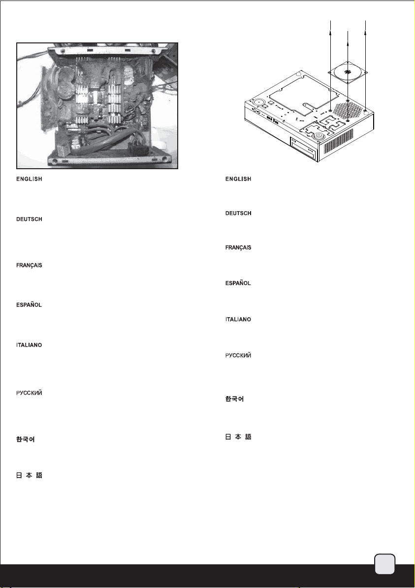
(2) Cleaning of filters on a regular basis is highly recommended
Picture: An example of a PSU that has malfunctioned due to it overfilled
with dust. To ensure long and optimal use of the installed PSU, we
recommend cleaning the PSU filters regularly every three months or half
a year (depending on your environment).
Abbildung: Beispiel eines Netzteils, bei dem es aufgrund von übermäßiger
Staubablagerung zu einer Fehlfunktion gekommen ist.Zur Gewährleistung
eines langen, optimalen Einsatzes des installierten Netzteils empfehlen
wir, die Netzteilfilter regelmäßig alle drei bzw. sechs Monate (je nach
Umgebung) zu reinigen.
Image : un exemple d'alimentation qui a mal fonctionné à cause de
l’excès de poussière.Pour assurer la pérennité de votre installation de
manière optimale nous vous recommandons de nettoyer régulièrement
les filtres, à savoir tous les trois ou six mois selon l’environnement.
Imagen: Un ejemplo de una FA que ha fallado debido a estar llena de
suciedad.Para asegurar una vida larga y óptima de la FA instalada, le
recomendamos que limpie a menudo los filtros de la FA, dependiendo
de su ubicación cada tres ó seis meses.
Immagine: Un esempio di un alimentatore che si è guastato a seguito
di un eccessivo accumulo di polvere. Per essere sicuri che il vostro
alimentatore godrà di lunga vita, vi raccomandiamo di provvedere alla
pulizia dei filtri almeno ogni tre o sei mesi (dipendentemente dalla tipologia
di ambiente).
Рисунок: пример блока питания, неисправность которого вызвана
загрязнением фильтров пылью. Для обеспечения длительного и
эффективного использования бл ока питания рекомендуется
регулярно выполнять очистку его фильтров с периодичностью раз
в три месяца или раз полгода (в зависимости от условий эксплуатации).
그림
: 먼지로 가득차 오동작을 하고 잇는 PSU의 예. 장착된 PSU을
장기간 최적화되게 사용하려면, PSU 사용환경에 따라 필터를 매 3개월
혹은 6개월마다 정기적으로 청소해주기 바랍니다.
図: ホコリが一杯になり故障したPSUの例。インストールされたPSUが
長く最適の使用状態を保てるよう、3ヶ月または半年(ご使用の環境に依存)
ごとに規則的にPSUフィルタを清掃するようお勧めします。
繁体中文
圖: 被灰塵卡死的電源供應器。
視環境而定,我們建議您每3個月~半年必須清理電源濾網。
简体中文
图: 被灰尘卡死的电源供应器。
视环境而定,我们建议您每3个月~半年必须清理电源滤网。
The illustration shows how to remove the PSU filter.
Die Abbildung zeigt, wie Sie den Netzteilfilter entfernen.
Cette illustration indique comment retirer les filtres de l'alimentation.
La ilustración muestra cómo quitar el filtro de la FA.
Di seguito la procedura di rimozione dei filtri delle ventole.
На рисунке показано, как снимать фильтр блока питания.
그림은 PSU 필터를 제거 하는 방법이 나타나 있습니다.
PSUフィルタの取り外し方は図に示されています。
繁体中文
圖為濾網的拆卸步驟。
简体中文
图为滤网的拆卸步骤。
28
Page 30
简体 中文
繁体 中文
Upgrade and maintenance
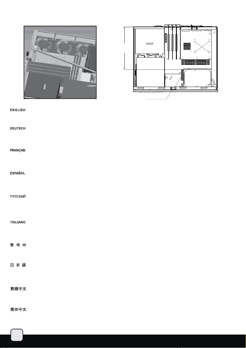
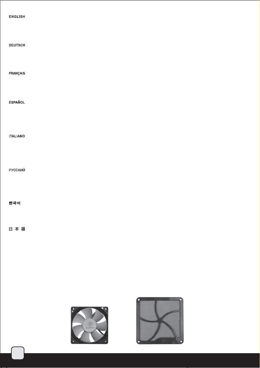
(3) The ML03 has an oversized CPU venting area on the top cover to ensure great cooling performance over the CPU area. If you require
additional cooling, we recommend installing four low speed 80mm fans such as SilverStone’s SUSCOOL81 to the right side of the case.
The installation order for the fans are to install the front and the rear fans first, then install the middle two fans last.
To prevent dust from falling into CPU vent area when the computer is not running, you can place the included FF141 filter over the CPU vent.
The filter is magnetized so it will stick to surface of the metal top cover.
(3) Das ML03 verfügt zur Optimierung der Kühlleistung oberhalb der CPU über eine überdimensionierte CPU-Belüftungsfläche an der oberen
Abdeckung. Wenn Sie die Kühlung noch weiter optimieren möchten, empfehlen wir die Installation von vier 80 mm-Lüftern mit geringer
Geschwindigkeit (z. B. SilverStones SUSCOOL81) auf der rechten Seite des Gehäuses. Installieren Sie dabei zuerst die Lüfter an der Vorderund Rückseite, dann die beiden Lüfter in der Mitte. Damit bei abgeschaltetem Computer kein Staub in die CPU-Belüftung eindringt, können Sie
den mitgelieferten FF141-Filter über die CPU-Belüftung legen. Der Filter ist magnetisch und haftet daher am Metalldeckel.
(3) Le ML03 possède des aération surdimensionnées pour le processeur pour assurer une bonne performance de refroidissement. S’il vous est
nécessaire de refroidir plus nous vous recommandons d’installer 4 petits ventilateurs de faible vitesse de rotation de 80 mm comme le SUSCOOL81
de Silverstone sur le coté droit du boitier. L’ordre d’installation étant tout d’abord les ventilateurs de devant et derrière et ensuite ceux du milieu.
Pour empêcher la poussière de tomber dans les aérations du processeur lorsque l'ordinateur ne fonctionne pas, vous pouvez placer le filtre FF141
inclus sur la zone du processeur. Le filtre est magnétisé et donc il recouvrira la surface métallique.
(3) La ML03 tiene una amplia zona de ventilación para la CPU en la cubierta superior para asegurar un alto rendimiento de la refrigeración sobre
la zona de la CPU. Si precisa de refrigeración adicional, le recomendamos que instale cuatro ventiladores de 80mm de baja velocidad como el
Silverstone SUSCOOL81 en el lado derecho de la carcasa. El orden de instalación de los ventiladores sería: instalar primero los ventiladores frontal
y trasero, luego los dos ventiladores del centro.Para evitar que el polvo caiga en la zona de ventilación de la CPU cuando el ordenador no esté
funcionando, puede situar el filtro FF141 incluido sobre el ventilador de la CPU. El filtro está magnetizado, por lo que se pegará a la superficie de
la cubierta de metal.
(3) ML03 possiede una sovradimensionata area di ventilazione sul cover superiore, in corrispondenza della CPU, al fine di garan
performance di raffreddamento. Qualora aveste bisogno di migliorare ulteriormente il sistema di ventilazione interno, vi consigliamo di installare
quattro ventole a bassa velocità nelle predisposizioni. Ad esempio potreste utilizzare quattro SilverStone SUSCOOL81. L’ordine di installazione
delle ventole è il seguente: prima la ventola frontale e la posteriore, poi quelle nel mezzo. Per evitare che la polvere si accumuli nella zona di
ventilazione della CPU quando il computer è spento, utilizzare il filtro FF141 incluso. Il filtro è magnetico, per cui aderirà alla superficie metallica
del top.
(3) На верхней крышке ML03 имеется большой участок для вентиляции ЦП для обеспечения эффективного охлаждения ЦП. При
необходимости дополнительного охлаждения рекомендуется установить в правую часть корпуса четыре вентилятора 80 мм малой скорости,
например SUSCOOL81 SilverStone. При установке вентиляторов сначала следует установить передний и задний вентиляторы, а затем
средние вентиляторы. С целью предотвращения
установить фильтр FF141, поставляемый в комплекте, над вентилятором ЦП. Фильтр намагничен, поэтому он примагнитится к поверхности
металлической защитной накладки.
ML03은 오버사이즈 CPU 통기구가 상부에 있어 우수한 냉각 CPU주변에 우수한 냉각 성능을 보장합니다. 만약 추가로 냉각이 필요하다면,
SilverStone의 SUSCOOL81 과 같은 80mm 팬을 4개 까지 케이스 오른편에 추가 장착 가능합니다. 팬의 설치 순서는 전면, 후면, 그리고,
중간의 두개 팬을 마지막에 설치하면 됩니다. 컴퓨터가 동작하지 않을 경우, CPU 환기구로 먼지가 유입되지 않게 하기위해, 동봉된 FF141
필터를 CPU 환기구에 설치 할 수 있습니다. 필터는, 자석이 붙어 있어, 철제 상부 커버에 별도의 장치 없이 장착됩니다.
(3) ML03は、CPUエリア上方の大きな冷却性能を確保するため、上部カバーに特大のCPU換気口を有しています。さらなる冷却が必要であれば、ケ
ース右側にSilverstone製SUSCOOL81などの低速度80mmファン4台をインストールするようお勧めします。ファンの取付け順序は、最初に前部と後部
ファンをインストールし、そして最後に間のファン2台をインストールします。コンピュータが動作していない間にCPU通気部分にホコリが落ちる
のを防止するため、付属のFF141フィルタをCPU開口部に装着できます。フィルタは金属上部カバーの表面に吸い付くよう磁化されています。
繁体中文
(3) SilverStone已經在CPU上方有開專用進風孔,以確保系統在任何配置下都能達到優良的散熱效能。如果您還想要增加CPU區塊的散熱效能,我們建議
您可以選購四顆SilverStone SUSCOOL 81,並安置在機殼右方。安裝順序為先安裝最前最後方的風扇,再裝入中間2顆風扇。為了預防灰塵在系統未開機
時,由CPU進風孔落入主機內部。建議使用者可以在CPU進風孔上方安裝FF141濾網,藉由磁鐵吸附的原理,FF141隨意放置在金屬機殼之上。
简体中文
(3) SilverStone已经在CPU上方有开专用进风孔,以确保系统在任何配置下都能达到优良的散热效能。如果您还想要增加CPU区块的散热效能,我们建议
您可以选购四颗SilverStone SUSCOOL 81,并安置在机箱右方。安装顺序为先安装最前最后方的风扇,再装入中间2颗风扇。为了预防灰尘在系统未开机
时,由CPU进风孔落入主机内部。建议使用者可以在CPU进风孔上方安装FF141滤网,藉由磁铁吸附的原理,FF141随意放置在金属机箱之上。
оседания пыли в зоне вентилирования ЦП в периоды бездействия компьютера можно
tire le massime
29
Suscool 81
FF141
Page 31
简体 中文
繁体 中文
Upgrade and maintenance
(4) VGA (D-sub) connector installation
Located near the first expansion slot of the case, there is a cutout in the shape of a VGA (D-sub) connector, this is designed to help save the
use of an expansion slot that may otherwise be taken up by the connector in a two slot low profile configuration. We recommend picking a
motherboard with graphics card slot located on the first slot and a graphics card with single low profile slot configuration to take advantage of
the VGA (D-sub) cutout implemented in the ML03.
In der Nähe des ersten Erweiterungssteckplatzes des Gehäuses befindet sich eine Ausfräsung in Form eines VGA- (D-Sub-) Anschlusses;
dadurch soll ein Erweiterungssteckplatz eingespart werden, der andernfalls bei einer Zwei-Steckplatz-Low-Profile-Konfiguration durch den
Anschluss benötigt werden würde. Damit Sie von der VGA- (D-Sub-) Ausfräsung des ML03 profitieren können, empfehlen wir die Wahl eines
Motherboards, bei dem die Grafikkarte im ersten Steckplatz installiert wird, sowie einer Grafikkarte mit Einzel-Steckplatz-Low-Profile-Konfiguration.
Situé à coté, au niveau du premier emplacement d’extension du boîtier, il y a une forme prédécoupée pour le connecteur VGA (D-sub), afin
de préserver l'utilisation d'un autre emplacement d'extension. Nous vous recommandons de choisir une carte mère avec des emplacements
de carte graphique situés sur le premier emplacement et une carte graphique low profile pour tirer avantage de l'emplacement du connecteur
VGA (D-sub) du ML03.
Localizado cerca del primer zócalo de expansión de la carcasa, existe un agujero en forma de conector VGA (D-sub) diseñado para ayudarle
a evitar el uso de un zócalo de expansión que de otro modo podría ser necesario para el conector en una configuración de dos zócalos. Le
recomendamos que escoja una placa base con zócalo para tarjetas gráficas situado en el primer zócalo y una tarjeta gráfica con una configuración
de un único zócalo de perfil bajo para así aprovecharse del agujero para VGA (D-sub) implementado en la ML03.
Situato nei pressi del primo slot di espansione, troviamo un pre taglio della forma di un connettore VGA (D-sub), è stato progettato per poter
salvare uno slot di espansione che sarebbe stato occupato da una VGA low profile in configurazione dual slot. Vi raccomandiamo di scegliere
una scheda madre con lo slot per vga situato in corrispondenza del primo slot di espansione ed una scheda grafica single slot a basso profilo
per poter trarre vantaggio dalla sede pre tagliata implementata in ML03.
Паз в форме разъема VGA (D-sub) расположен рядом с первым слотом расширения в корпусе и предназначен для обеспечения
возможности использования слота расширения, который может быть закрыт разъемом при конфигурации с двумя слотами малого
размера. Рекомендуется выбирать материнские платы с разъемом под графическую карту, расположенным в первом слоте, и
графические
첫번째 확장슬롯 근처에, VGA (D-SUB) 커텍더 모양의 구멍이 있어 LP 두개의 슬롯 사용시에 사용할 수 없는 확장슬롯을 사용할 수
해 줍니다. 메인보드 선택시에 그래픽 카드 슬롯이 첫번째 에 위치하고, 그래픽 카드가 싱글 LP 슬롯 구성을 갖고 있는 제품을 선택해,
ML03의 VGA(D-SUB) 을 활용 할 수 있기를 권장합니다.
ケースの1番目の拡張スロットの近くに、VGA(D-sub)コネクタの形をした開口部がありますが、これは、異なる形状の2つのスロットでロー
プロファイル構成を行った場合、拡張スロットが使用するコネクタを確保できるように設計されています。ML03に採用されたVGA(D-sub)開
口部を利用するには、1番目のスロットがグラフィックカードでロープロファイルスロット構成を有するマザーボードを選択するようお勧め
します。
繁体中文
ML03在最靠近第一槽介面卡有多一個不斷孔以支援VGA插座,此設計可以在有需要用到此VGA插座時,儘量減少介面卡位置的佔用。如果您有需要
用到此插座,建議在選購主機板與介面卡時,就先注意能否支援;我們建議選用顯示卡插槽在第一槽的主機板,與提供有單槽底矮擋板的顯示卡。
简体中文
ML03在最靠近第一槽适配卡有多一个不断孔以支持VGA插座,此设计可以在有需要用到此VGA插座时,尽量减少适配卡位置的占用。如果您有需要
用到此插座,建议在选购主机板与适配卡时,就先注意能否支持;我们建议选用显示卡插槽在第一槽的主机板,与提供有单槽底矮挡板的显示卡。
карты с одним слотом малого размера, чтобы можно было использовать паз для разъема VGA (D-sub) в ML03.
있돌고
30
Page 32

简体 中文
繁体 中文
Upgrade and maintenance
A.
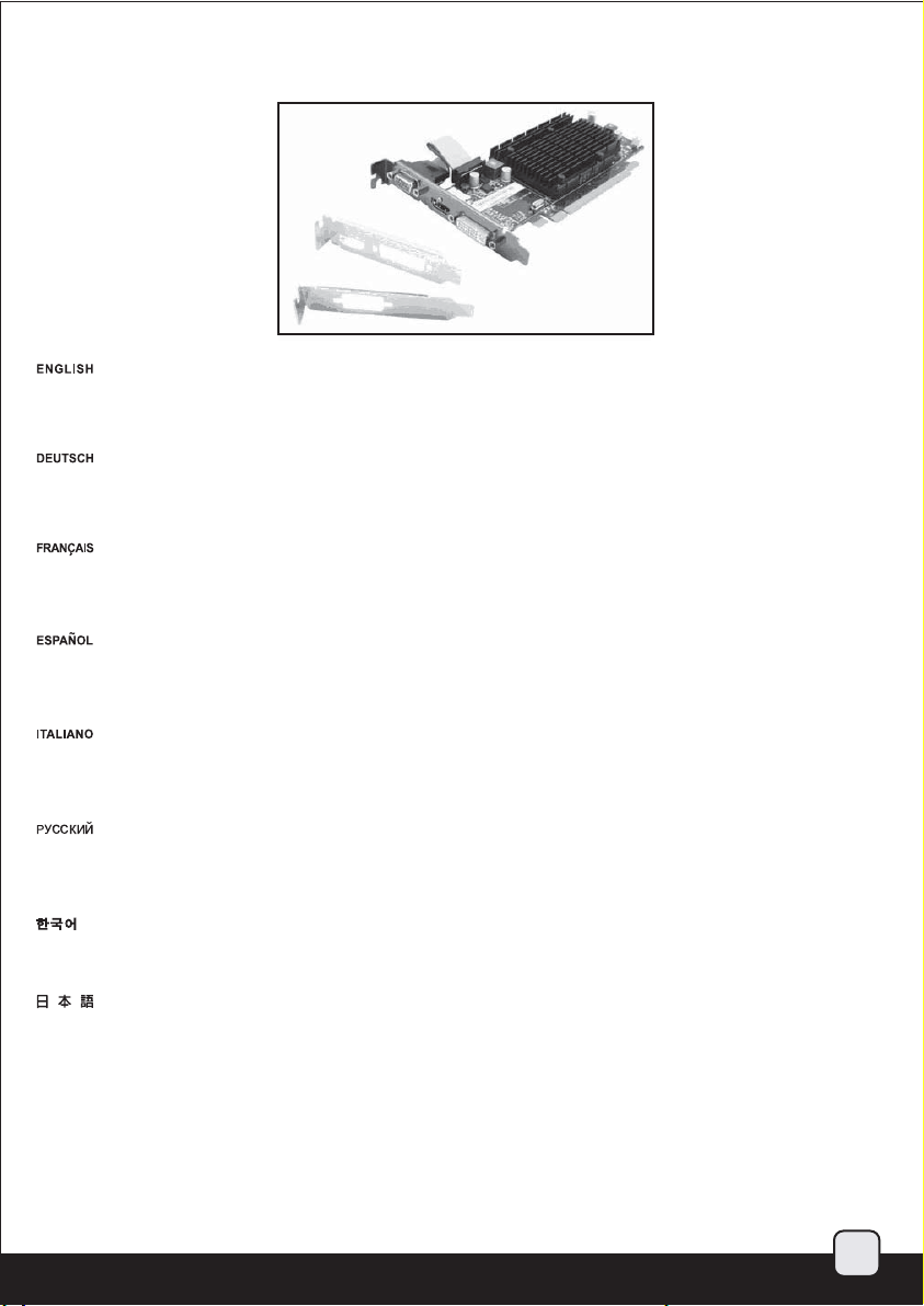
A: Motherboard such as the one pictured with graphics card slot in the second slot may prevent the use of VGA (D-sub) cutout due to longer
distance required for the graphics card ribbon cable.
B: Graphics card that comes with dual fixed low profile slot bracket will not benefit from the use of ML03’s VGA (D-sub) cutout as the slot design
takes up two slots.
A: Bei Motherboard-Modellen, bei denen die Grafikkarte im zweiten Steckplatz installiert wird (vgl. Abbildung), können Sie die VGA- (D-Sub-)
Ausfräsung aufgrund des für das Flachbandkabel der Grafikkarte erforderlichen Abstandes möglicherweise nicht nutzen.
B: Grafikkarten mit dualer Low-Profile-Steckplatzhalterung ermöglichen nicht die Verwendung der VGA- (D-Sub-) Ausfräsung, da das
Steckplatzdesign zwei Steckplätze erfordert.
A: Les cartes mères comme celle illustré ayant l'emplacement pour la carte graphique au deuxième emplacement ne pourront pas bénéficier de
l'utilisation de l'emplacement du connecteur VGA (D-sub) du ML03 à cause de la distance entre l'équerre et la carte graphique trop important
pour la nappe fournie.
B: Les cartes graphiques qui sont livrés avec une double équerre low profile ne pourront pas bénéficier de l'utilisation de l'emplacement du
connecteur VGA (D-sub) du ML03.
A: Una placa base como la de la imagen con espacio para la tarjeta gráfica en el segundo zócalo podría evitar el uso del agujero para VGA (D-sub)
debido a la mayor distancia necesaria para el cable de la tarjeta gráfica.
B: Las tarjetas gráficas que vienen con un bracket con zócalo doble fijo no se beneficiarán del uso del agujero para VGA (D-sub) de la ML03, ya que
el diseño necesita de dos zócalos.
B.
A: Una scheda madre come quella in figura, con lo slot per la vga situato in corrispondenza del secondo slot di espansione del case, potrebbe
impedire l’utilizzo della sede aggiuntiva per il connettore VGA (D-sub) a causa della limitata lunghezza del flat di connessione.
B: Schede grafiche con staffa dual slot non beneficieranno dell’utilizzo del pre taglio per il connettore VGA (D-sub) a causa della configurazione
dual slot nativa.
A: При использовании материнской платы, как показано на рисунке, с разъемом для графической карты во втором слоте не удастся
использовать разъем VGA (D-sub), так как для плоского кабеля графической карты потребуется больше места.
B: При использовании графических карт с двойным держателем слота не удастся использовать паз VGA (D-sub) на ML03, так как
конструкция разъема включает два слота.
A: 그림에서와 같이 메인보드 중 그래픽 카드 슬롯이 두번째에 위치 할 경우 VGA(D-SUB) 활용이 리본 케이블의 길이 제한 등으로 어려울
수 있습니다.
B: 그래픽 카드중 듀얼 고정 LP 슬롯 브라켓은 디자인상 두개의 슬롯을 차기
A: 図のような2番目のスロットにグラフィックカードスロットを有するマザーボードでは、グラフィックカードリボンケーブルにさらに長い
距離が必要とされるので、VGA(D-sub)開口部が使用できなくなります。
B: デュアルの固定されたロープロファイルスロットブラケットが付属するグラフィックカードは、スロット設計が2つのスロットを採用して
いるので、ML03のVGA(D-sub)開口部の使用からのメリットはなくなります。
繁体中文
A: 顯示卡擴充槽在第二槽,可能讓VGA排線不夠長。
B: 顯示卡配件的矮擋板是佔用雙槽式的,即使利用了我們機殼的VGA插座也無法得到任何好處。
简体中文
A: 显示卡扩充槽在第二槽,可能让VGA排线不够长。
B: 显示卡配件的矮挡板是占用双槽式的,即使利用了我们机壳的VGA插座也无法得到任何好处。
하기 때문에 ML03의 VGA(D-SUB) 구멍을 이용할 수 없습니다.
31
Page 33

简体 中文
繁体 中文
Upgrade and maintenance
Installation steps:
1.
Use a hex screwdriver to remove the standard sized slot from the graphics card.
Entfernen Sie mit einem Sechskantschraubendreher den Standardsteckplatz von der Grafikkarte.
Utilisez un tournevis hexagonal pour retirer les emplacements de la carte graphique.
Use un destornillador hex para quitar el zócalo de tamaño estándar de la tarjeta gráfica.
Utilizzare un cacciavite a testa esagonale per rimuovere la staffa standard dalla VGA.
Используйте шестигранную отвертку для снятия разъема стандартного размера графической карты.
육각 드라이버를 이용해, 일반적인 크기의 슬롯을 그래픽 카드에서 제거합니다.
六角ドライバーで、標準サイズのスロットをグラフィックカードから取り外します。
繁体中文
準備六角套筒起子,將顯示卡上原本的VGA插座拆下。
简体中文
准备六角套筒起子,将显示卡上原本的VGA插座拆下。
32
Page 34
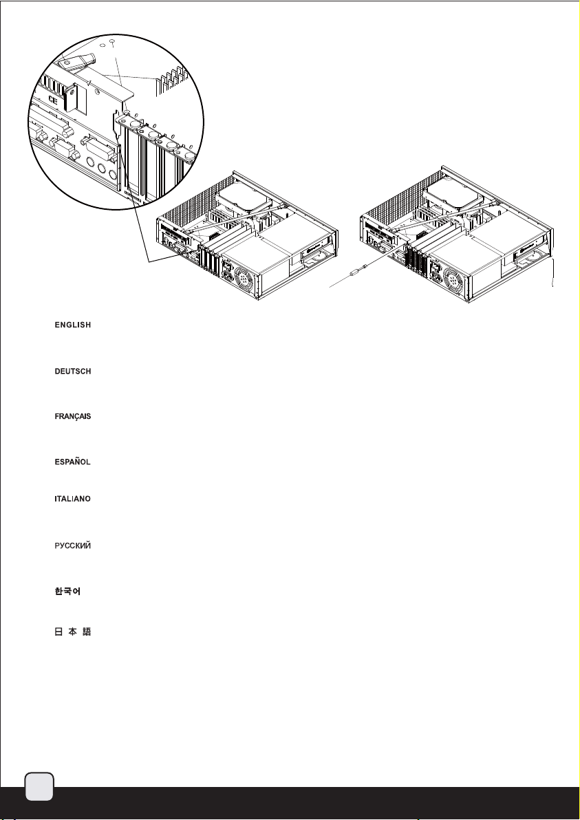
简体 中文
繁体 中文
2.
Break the VGA (D-sub) cutout from the case and install the VGA (D-sub) connector.
The case’s cutout supports mounting of the connector in both orientations so you may choose one that best suit your graphics
card’s requirement.
Durchstoßen Sie die VGA- (D-Sub-) Ausfräsung des Gehäuses und installieren Sie den VGA- (D-Sub-) Anschluss.
Die Ausfräsung des Gehäuses unterstützt die Montage des Anschlusses in beide Richtungen; wählen Sie die am besten für Ihre
Grafikkarte geeignete Option.
Retirer le cache prédécoupé pour le connecteur VGA (D-sub) et installez le connecteur VGA (D-sub).
Le cache prédécoupé du boîtier peut subir n’importe quelle orientation de montage selon les nécessités dues aux contraintes de
votre carte graphique.
Abra el agujero precortado para VGA (D-sub) de la carcasa e instale el conector VGA (D-sub). El agujero de la carcasa acepta montar
el conector en ambas direcciones, luego podría escoger la más adecuada para su tarjeta gráfica.
Break the VGA (D-sub) cutout from the case and install the VGA (D-sub) connector.
The case’s cutout supports mounting of the connector in both orientations so you may choose one that best suit your graphics
card’s requirement.
Сделайте паз VGA (D-sub) в корпусе и установите разъем VGA (D-sub).
Паз в корпусе позволит установить разъем в обоих направлениях, поэтому можно выбрать необходимый вариант в
зависимости от графической карты.
VGA(D-SUB)가 있는 곳의 철판을 제거해, VGA(D-SUB) 커넥터를 설치합니다.
케이스의 구멍은 커넥터 마운팅을 양쪽방향에서 모두 지원하기 때문에 그래픽 카드에 맞는 적절한 방향으로 설치 바랍니다.
ケースからVGA(D-sub)開口部を開け、VGA(D-sub)コネクタをインストールします。
ケースの開口部は両方の方向のコネクタ設置をサポートするので、グラフィックカードの必要条件に最適な向きを選ぶことができます。
繁体中文
扭開機殼上的不斷孔,將VGA插座裝上去;
機殼上的孔位是配合各種不同的顯示卡,可以正反安裝,請根據您的顯示卡需求,選一種最好的方向安裝。
简体中文
扭开机壳上的不断孔,将VGA插座装上去;
机壳上的孔位是配合各种不同的显示卡,可以正反安装,请根据您的显示卡需求,选一种最好的方向安装。
33
Page 35

Page 36
September, 2010
NO: G11212480
 Loading...