

Page 1

Mammoth Series
MM01
Professional chassis with integrated HEPA filter
for harsh or critical environments
Page 2

Installation and system optimization guide:
Specification
P.2
Introduction
P.1
Disassemble chart
P.3
Installation guide
P.5
Connector definition
P.17
Front I/O connector guide
P.19
Component size limitations
P.20
CPU and graphic card supporter
P.29
Optimal Thermal Performance Layout
P.32
Upgrade And Maintenance
P.39
Warranty Information
P.47Q & A
P.55
The following manual and guides were carefully prepared by the SilverStone engineering team
to help you maximize the potential of your SilverStone product. Please keep this manual for
future reference when upgrading or performing maintenance on your system. A copy of this
manual can also be downloaded from our website at:http://www.silverstonetek.com
Page 3
The following manual and guides were carefully prepared by the SilverStone engineering team to
help you maximize the potential of your SilverStone product. Please keep this manual for future
reference when upgrading or performing maintenance on your system. A copy of this manual can also
be downloaded from our website at:
http://www.silverstonetek.com
Installation and system optimization guide:
Product Overview
Specifications
Disassemble Chart
Installation Guide
Connector Definition
Front I/O connector Guide
Component Size Iimitations
CPU And Graphic Card Supporter
Optimal Thermal Performance Layout
Upgrade And Maintenance
Q&A
Warranty Information
P.1
P.2
P.3
P.5
P.17
P.19
P.20
P.29
P.33
P.39
P.47
P.55
Page 4
Product Overview
1
Introduction
For computer designers, creating a chassis capable of surviving harsh environments is a tough task, especially if dust
is a major problem. Most resort to fanless configuration as this eliminates the possibility of dust buildup introduced by active
airflow into the chassis, which is the main cause of system overheating over time. But limited heat dissipation capacity
afforded by fanless designs confines systems to lower powered CPUs and Mini-ITX boards with less features.
To overcome this limitation, SilverStone’s R&D team once again challenged and overturned convention by coming up
with an answer in the Mammoth MM01 chassis. Instead of completely sealing off airflow to prevent dust, the MM01 has a
partially-sealed design with active filtering. To prevent dust from entering the chassis, a HEPA filter is used to cover the air
intake area, making MM01 the first retail computer chassis to incorporate this internationally recognized filtering technology.
Used frequently by clean room in factories, operating room in hospitals, or facilities requiring dust-free environment, the
HEPA filter has the ability to remove airborne particles far exceeding what’s available in traditional computer equipments.
In order for this to work without suffocating airflow, two Air Penetrator fans were selected for use in the MM01. With a
combined rating of up to 340CFM, they provide air pulling power similar to typical household fans and make it possible to
maintain proper cooling for high-end components despite the presence of highly restrictive HEPA filters.
Complementing the tremendous ability to keep dust at bay, the MM01 also has unique, downward slanting front and
rear vents to keep liquid from flowing in from the top of the chassis. This simple, yet affective design helps MM01 take on
much harsher conditions required by professionals working in places not normally suitable for computers. For those
choosing to use MM01 in normal home or office, its superior filtering could potentially help clean up the working environment
as well!
Mammoth Series MM01
Page 5

Product Overview
2
Aluminum door, plastic anti-splash grille, steel panels and body
SSI-EEB, SSI-CEB, Extended ATX, ATX, Micro-ATX
Front
SST-MM01B (black)
USB 3.0 x 2 audio x 1 MIC x 1
1 x Optional standard PS2 (ATX) no length limitation
Compatible up to 13.3” long, width restriction-6.69”
183mm
8
271mm (W) x 542mm (H) x 597mm (D), 87.69 liters
Includes HEPA filter
*AP182’s original top speed is 2000rpm, but high resistance introduced by HEPA filter reduces top speed
by 200rpm.
3.5" x 7 ( hot-swap x1 ) , 2.5” x 4
2 x AP182 180mm intake fan 500~1800rpm*, 17~42 dBA
5.25" x 2
Internal
1 x 120mm fan slotRear
Exposed
Specifications
Material
Model
Motherboard
Drive Bay
Cooling System
Expansion Slot
Front I/O Port
Power Supply
Expansion Card
Limitation of CPU cooler
Dimension
Extra
Mammoth Series MM01
Page 6
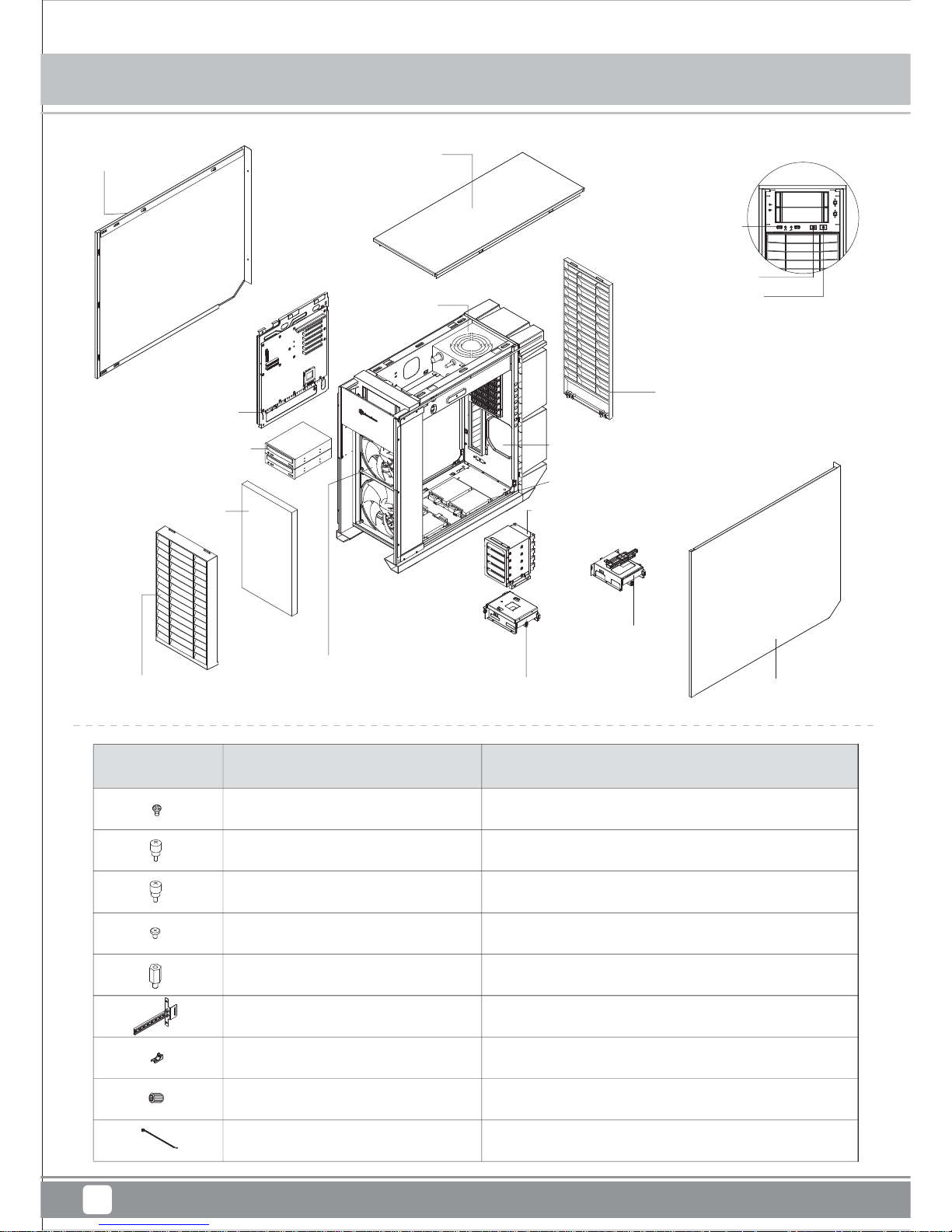
Disassemble Chart
3
Secure 2.5” HDD
Secure optical drives
Secure VGA holder and claw
Secure PSU, 12025 fan, motherboard and 3.5” HDD
Motherboard standoff
VGA supporter holder
VGA supporter claw
Standoff socket wrench
Cable management
SCREW - P - M3 4 - BK
SCREW - THUMB - M3 6 - BK
SCREW - THUMB - 6 - 32 6 - BK
SCREW - I - 6 - 32 5 - BK
STANDOFF - 6 - 32 6.5H - 6 - 32
VGA - SUPPORT - HOLDER
VGA - SUPPORT - CLAW
STANDOFF - SOCKET - WRENCH
BUNCH - WIRE - TIES
PICTURE ITEM PURPOSE
PSU (OPTION)
TOP COVER
REAR PANEL
RIGHT PANEL
FRONT PANEL
5.25” DRIVE BAY x 2
MOTHERBOARD TRAY
180 FAN x 2 OR
120 FAN x 3 (OPTION)
3.5” DRIVE BAY x 1
3.5” DRIVE BAY x 1
2.5” DRIVE BAY x 4
120 FAN x 1 (OPTION)
3.5” DRIVE BAY x 5
HEPA Filter
LEFT PANEL
USB3.0 x 2 + SPK + MIC
RESET BUTTON
POWER BUTTON
Mammoth Series MM01
*
*
*
*
*
Page 7
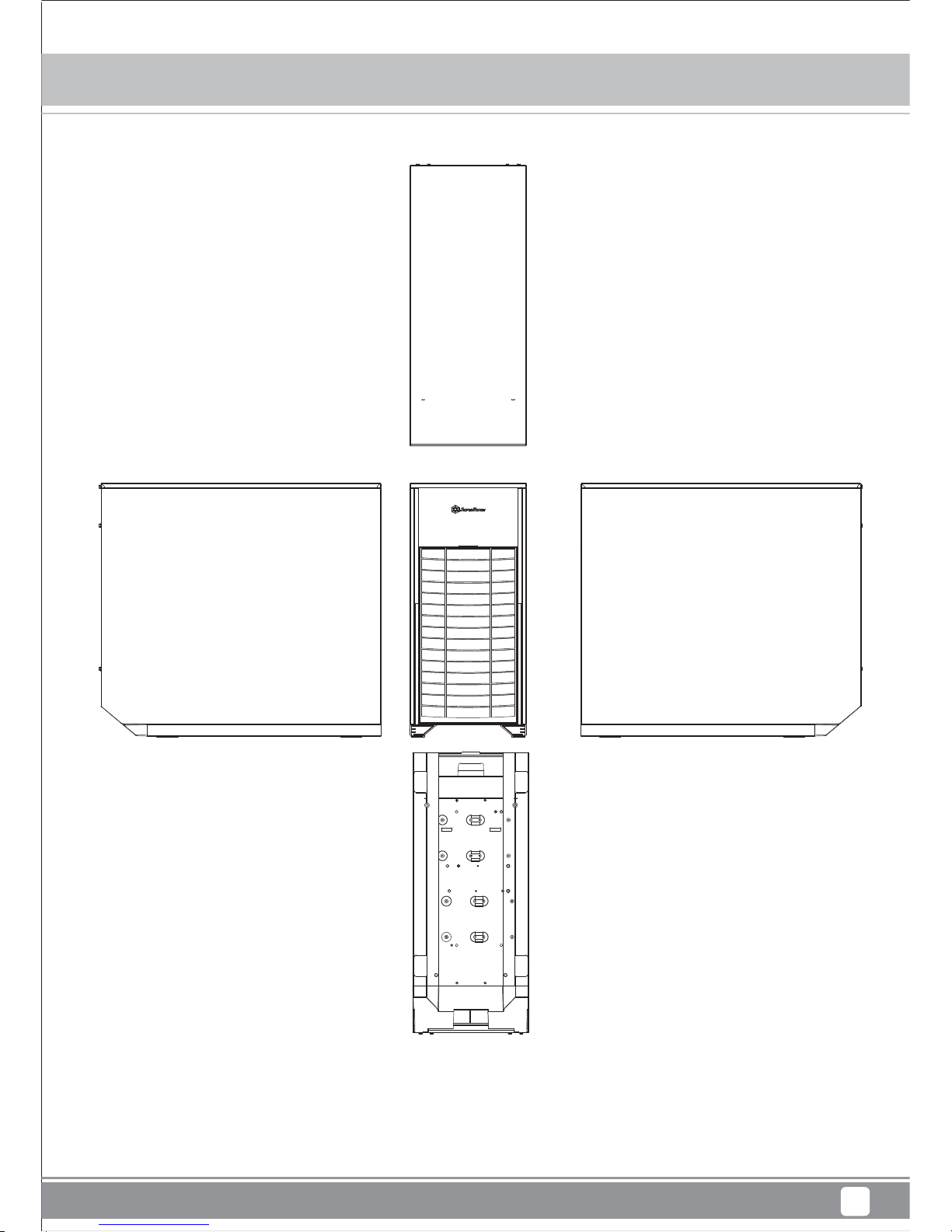
Disassemble Chart
4
Mammoth Series MM01
Page 8
Installation guide
5
Before you begin, please make sure that you
have all components collected
check that all components do not have compatibility problems with each other or with the case
if possible, assemble the components outside the case first to make sure they are working
keep the motherboard manual ready for reference during installation
1
2
3
4
01
02
Lösen Sie die beiden Schrauben
an den linken und rechten
Seitenwänden, nehmen Sie die
Seitenwände ab.
Desserrez les vis des deux
panneaux latéraux pour les
retirer.
Desatornille dos tornillos de los
paneles izquierdo y derecho para
quitarlos.
Per rimuovere i pannelli laterali
allentare, per entrambi, le due
viti di serraggio.
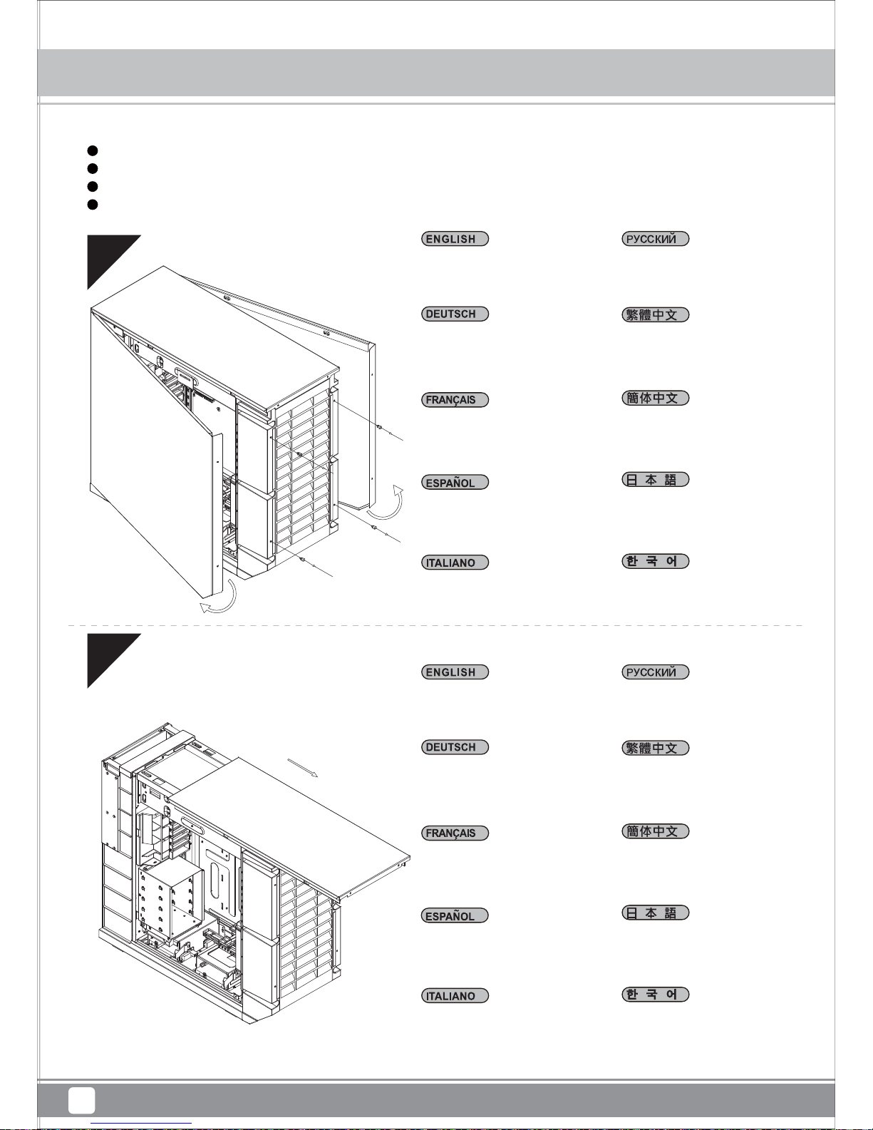
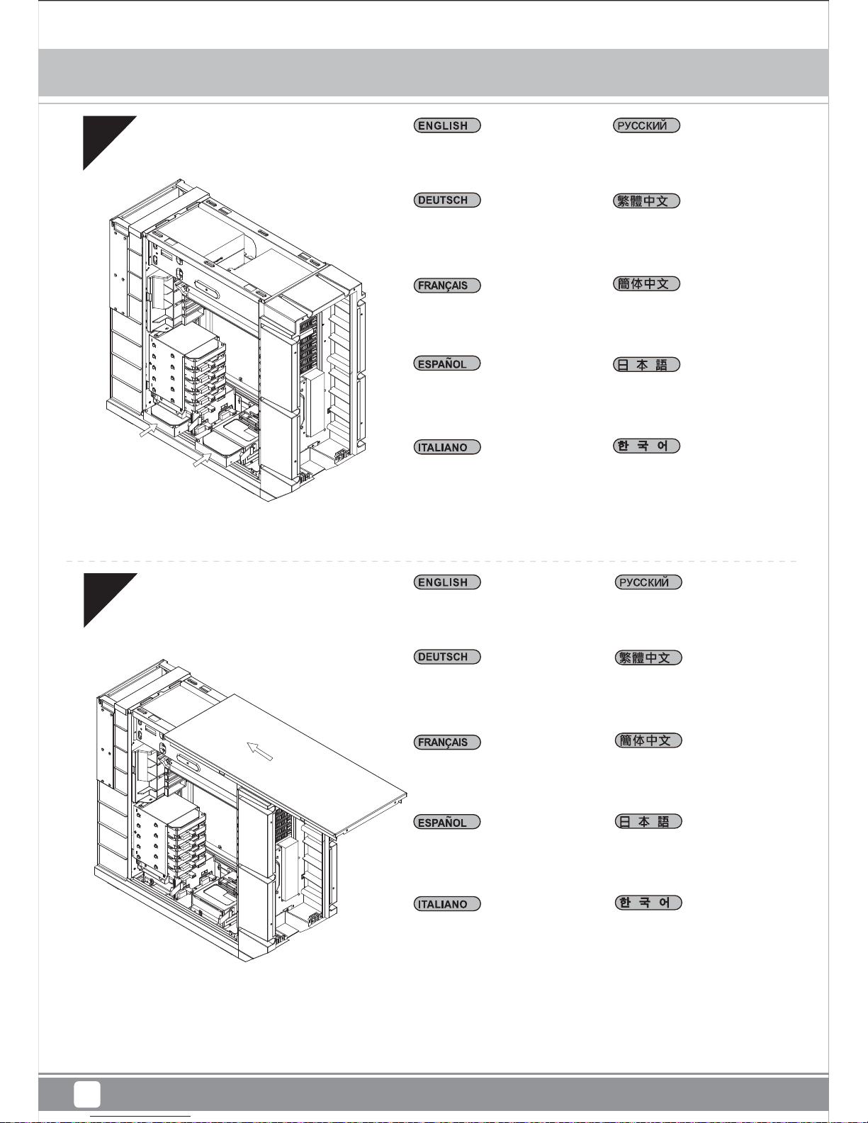
Loosen two screws from both
left and right side panels to
remove them.
Отвинтите по два винта,
крепящих левую и правую
боковых панели, и снимите
панели.
왼쪽과 오른쪽 사이드 패널에서
두 개씩 나사를 풀어 사이드
패널을 제거합니다.
取下左右側板各兩顆螺絲,
卸下側板。
取下左右侧板各两颗螺丝,
卸下侧板。
両方の左右パネルからネジ
2本を緩めて、取り外します。
Entfernen Sie die obere Blende,
indem Sie sie nach hinten
drücken.
Retirez le panneau supérieur en
le poussant vers l'arrière.
Retire el panel superior tirando
de él hacia la parte posterior.
Allentare le due viti sul lato
posteriore del telaio e poi
rimuovere il coperchio superiore.
Remove top panel by pushing
it toward the rear.
Снимите верхнюю панель,
переместив ее назад.
뒤쪽으로 밀어 상단 패널을
분리하십시오.
將上蓋往後推,取下上蓋。
将上盖往后推,取下上盖。
上部パネルを後方に
押して取り外します。
Mammoth Series MM01
Page 9
03
04
Lösen Sie die drei Schrauben,
welche die MotherboardHalterung fixieren, nehmen
Sie die Halterung ab.
Desserrez les trois vis tenant le
plateau de la carte mère pour le
démonter.
Desatornille tres tornillos que
sujetan la bandeja de la placa
base para quitarla.
Per rimuovere il supporto
scheda madre allentare le
tre viti di serraggio.
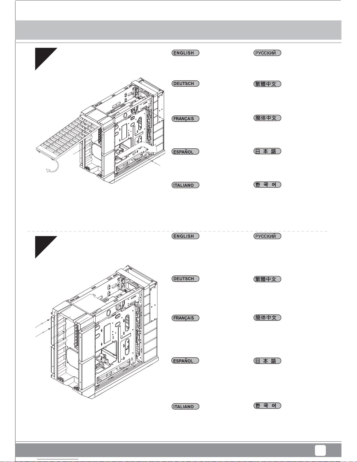
Loosen three screws holding
the motherboard tray to
remove it.
Отвинтите три винта,
крепящих кронштейн
материнской платы, и
снимите его.
3개의 나사를 풀어 메인보드
트레이를 제거합니다.
取下主機板托盤3顆螺絲,
將主機板托盤抽出。
取下主板托盘3颗螺丝,
将主板托盘抽出。
マザーボードトレイを固定
しているネジ3 本を緩 めて、
取り外します。
將電源供應器由上放入機殼內,
如果有12公分或以上尺寸的
風扇建議朝下放置。
将电源供应器由上放入机壳内,
如果有12公分或以上尺寸的
风扇建议朝下放置。
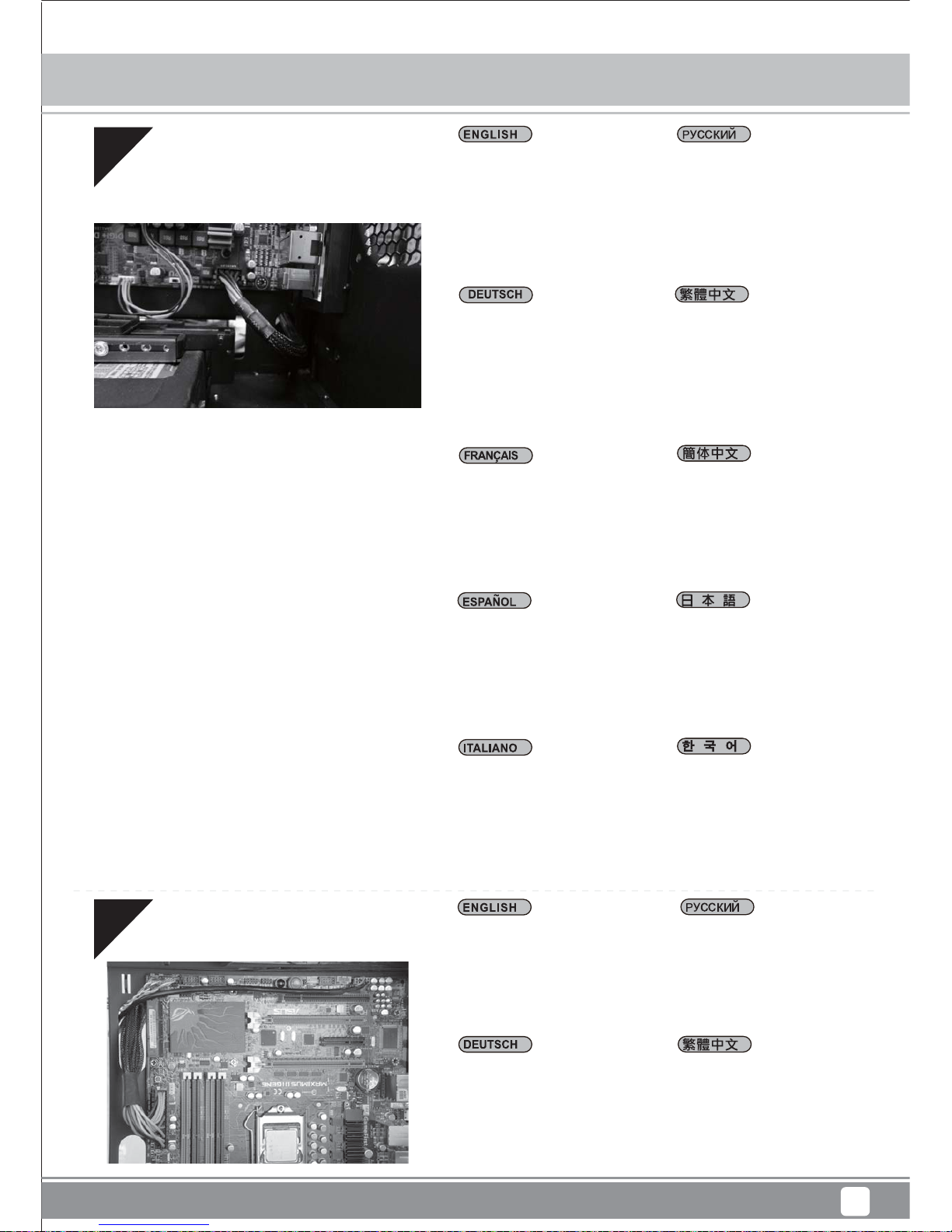
Insert the power supply from
the top, if the power supply has
a build-in 120mm fan or larger,
we recommend installing the
power supply with its fan facing
down.
Установите блок питания в
верхней части корпуса. Если
блок питания оснащен
встроенным вентилятором
размером 120 мм или
больше, рекомендуется
устанавливать блок питания
вентилятором вниз.
電源は上面から入れます。電
源に120mm以上のファンが内
蔵されている場合、電源のフ
ァンが下向きになるよう設置
することを推奨します。
전원 공급장치에 120mm
이상의 내장 팬이 있는 경우,
상단에서 전원 공급장치를
삽입하십시오. 팬이 아래쪽을
향하도록 전원 공급장치를
설치하는 것이 좋습니다.
Setzen Sie das Netzteil von
oben ein; sofern das Netzteil
über einen120 mm-Lüfter (oder
größer) verfügt, empfehlen wir,
das Netzteil mit dem Lüfter
nach unten einzubauen.
Insérez la source
d'alimentation d'en haut, si la
source d'alimentation a un
ventilateur intégré de 120mm
ou plus, nous vous
recommandons d'installer la
source d'alimentation avec le
ventilateur face vers le bas.
Inserte la fuente de
alimentación desde arriba, si
la fuente de alimentación tiene
un ventilador de 120mm o
mayor incorporado, le
recomendamos instalar la
fuente de alimentación con el
ventilador hacia abajo.
Inserire l'alimentatore dall'alto,
se l'alimentatore ha una
ventola integrata da
120mm - o più grande; si
raccomanda di installare
l'alimentatore con la sua
ventola rivolta verso il basso
Installation guide
6
Mammoth Series MM01
Page 10
05
06
Nehmen Sie die 3,5
Zoll-Laufwerkhalterung
heraus.
Retirez le casier des
lecteurs 3.5”.
Quite la carcasa para
dispositivos de 3,5”
Rimuovere il supporto hard
drive da 3,5”
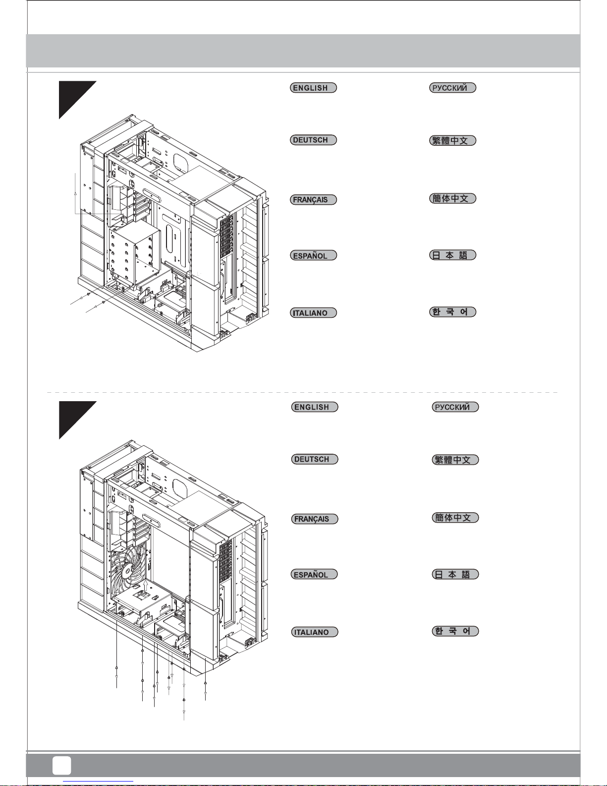
Remove 3.5” drive cage.
Извлеките кронштейн для
3,5-дюймовых жестких
дисков.
3.5” 드라이브 케이지를
제거합니다.
移除3.5吋主硬碟架。
移除3.5吋主硬盘架。
3.5インチドライブケージを取
り外します。
Lösen Sie die Schrauben,
welche den unteren
Festplattenkäfig fixieren,
nehmen Sie den Käfig ab.
Dévissez les vis pour l'enlever
en tenant la cage du lecteur
inférieur pour le retirer.
Afloje los tornillos sujetando
la carcasa para discos inferior
para retirarla.
Allentare le viti che fissano il
cage unità inferiore per
rimuoverlo.
Loosen the screws holding
the lower drive cages to
remove them.
Отверните винты крепления
нижнего отсека для жестких
дисков и извлеките его.
하단 드라이브 케이지를
고정하는 나사를 풀어
케이지를 분리하십시오.
拆除底部硬碟架螺絲,
取下硬碟架。
拆除底部硬盘架螺丝,
取下硬盘架。
下部ドライブケージを保持
しているネジを ゆるめて
取り外します。
Installation guide
7
Mammoth Series MM01
Page 11

07
08
Installieren Sie das 2,5
Zoll-Laufwerk im unteren Teil
des Gehäuses; anschließend
mit Schrauben fixieren.
Installez le lecteur 2.5” dans le
bas du boîtier et fixez-le avec
des vis.
Instale el disco de 2,5” en la
parte inferior de la carcasa y
fíjelo con tornillos.
Installare il drive da 2,5” nella
parte bassa dello chassis ed
assicurarlo alla struttura con le
viti in dotazione.
Install 2.5” drive into the bottom
of the chassis and secure with
screws.
Установите 2,5-дюймовый
жесткий диск в нижнюю
часть корпуса и закрепите
его винтами.
2.5”드라이브를 케이스 바닥에
장착한 후 나사로 고정합니다.
將2.5吋硬碟裝入機殼底部,
並鎖上螺絲。
将2.5吋硬盘装入机壳底部,
并锁上螺丝。
ケース底部に2.5インチドライブ
を装着し、ネジで固定します。
Bringen Sie den unteren
Festplattenkäfig wieder an.
Wenn Sie den CP05 nutzen
möchten, können Sie ihn jetzt
installieren.
Réinstallez la cage de lecteur
inférieur. Si vous voulez utiliser
le CP05, vous pouvez l'installer
maintenant.
Reinstale la carcasa para discos
inferior. Si desea instalar la CP05,
lo puede hacer ahora.
Installare di nuovo la gabbia unità
inferiore. Se si vuole usare CP05,
è possibile installarlo adesso.
Reinstall the lower drive cage.
If you want to utilize CP05, you
can install it now.
Установите на место нижний
отсек для жестких дисков.
Если вы хотите использовать
CP05, вы можете установить
его прямо сейчас.
하단 드라이브 케이지를 다시
설치합니다. CP05를
활용하려면 지금 이를 설치할
수 있습니다.
將底部硬碟架裝回,如果有需
要安裝CP05,可在這時安裝。
将底部硬盘架装回,如果有需
要安装CP05,可在这时安装。
下部ドライブケージを再び取
り付けます。CP05の利用を希望
する場 合、今取り付けることが で
きます。
Installation guide
8
Mammoth Series MM01
Page 12
09
10
Installieren Sie das hintere
I/O-Blech im Gehäuse.
Installez la plaque arrière de la
carte mère dans le boîtier.
Instale la placa trasera de E/S
de la placa base en la carcasa.
Installare la placca I/O della
scheda madre nella sede
preposta.
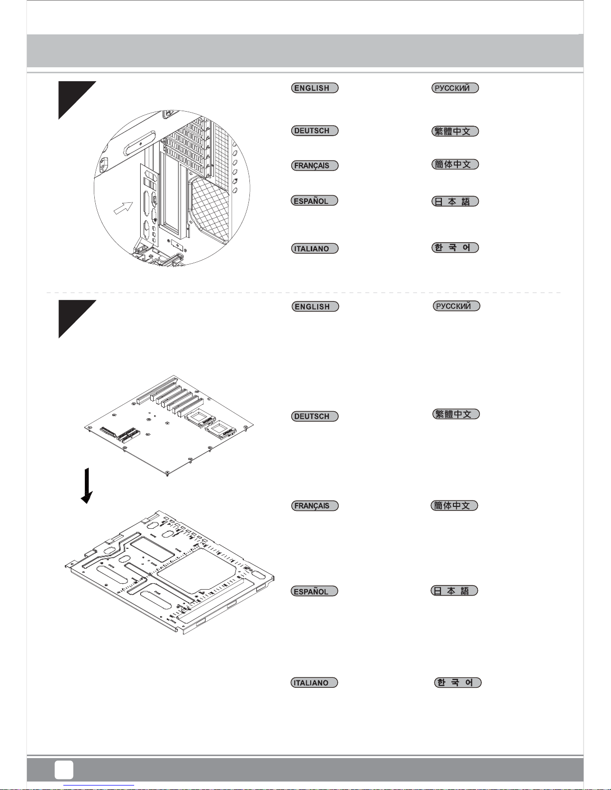
Install motherboard rear I/O
plate into the chassis.
Установите в корпус заднюю
панель ввода-вывода
материнской платы.
메인보드 후방 I/O 판을
케이스에 장착합니다.
將I/O彈片裝上機殼。
将I/O弹片装上机壳。
ケース内にマザーボード後部
I/ Oプレ ートをインストールし
ます。
Installieren Sie das Motherboard
auf der Motherboard-Halterung.
Sofern Sie bereits einen großen
CPU-Kühler auf dem Motherboard
installiert haben, empfehlen wir,
die 4-poligen ATX12V- oder
8-poligen EPS-Kabel vom
Netzteil jetzt an das Motherboard
anzuschließen; dies erleichtert
die weitere Installation.
Instale la placa base en la
bandeja de la placa base.
Si ya tiene instalado un
disipador grande de CPU
en la placa base, le
recomendamos que conecte
los cables ATX12V 4 pines ó
EPS 8 pines de su fuente de
alimentación a la placa base ahora
para que la instalación sea más fácil
después.
Installare la scheda madre sul
supporto. Se avete già montato
un dissipatore per CPU di grandi
dimensioni, vi consigliamo di
collegare i connettori dei cavi
ATX12V 4pin o EPS 8pin dell’
alimentatore subito, per renderne
più semplice la connessione.
Install motherboard onto the
motherboard tray. If you have
already installed a large CPU
cooler on the motherboard,
we recommend connecting
ATX12V 4pin or EPS 8pin
cables from your power supply to
the motherboard now to make
installation easier later on.
Установите материнскую
плату на кронштейн
материнской платы. Если на
материнскую плату уже
установлен процессорный
кулер большого размера, на
данном этапе рекомендуется
подсоединить к материнской
плате 4-контактный разъем
кабеля ATX 12 В или
8-контактный разъем кабеля
EPS от блока питания для
упрощения дальнейшего
процесса установки.
메인보드를 메인보드 트레이에
설치합니다. 메인보드에 커다란
CPU쿨러를 설치한 경우,
ATX12V 4핀이나 EPS 8핀
케이블을 파워 서플라이에서
메인보드로 미리 연결하여,
나중의 설치를 편하게 합니다.
將主機板安裝於主機板托盤,
如果您已經裝上大型CPU散熱器,
我們建議您先在機殼外把
ATX 4Pin / EPS 8pin插上電
源線。如果電源線夠長或為模
組化電源線,安裝步驟將更為
順利。
将主板安装于主板托盘,如果
您已经装上大型CPU散热器,
我们建议您先在机壳外把
ATX 4Pin / EPS 8pin插上电
源线。如果电源线够长或为模
块化电源线,安装步骤将更为
顺利。
マザーボードトレイ上にマザー
ボードを取り付けます。マザー
ボードに大型CPUクーラーがイ
ンストール済みならば、あとの
インストールが容易に行えるよう、
電源からATX12V4ピンまたは
EPS8ピンケーブルをマザーボ
ードにこの時点で接続しておく
ようにお勧めします。
Installez la carte mère sur son
support. Si vous avez déjà installé
un dissipateur de processeur de
grande taille sur la carte mère,
nous vous recommandons de
brancher tout de suite les câbles
ATX12V 4pin ou EPS 8pin de
votre alimentation à sur votre carte
mère pour rendre l'installation plus
facile plus tard.
Installation guide
9
Mammoth Series MM01
Page 13
11
12
Setzen Sie die MotherboardHalterung nebst Motherboard
wieder in das Gehäuse ein. Sofern
Sie das 4-polige ATX12V- oder
das 8-polige EPS-Kabel bereits
angeschlossen haben, achten Sie
darauf, dass das Kabel durch die
Öffnung zwischen Netzteil und
Motherboard verläuft.
Reinstale la bandeja de la placa
base montada de nuevo en el
chasis. Si tiene instalado el cable
ATX12V 4 pines ó EPS 8 pines,
asegúrese por favor de haberlos
pasado a través de la abertura
entre la fuente de alimentación y
el compartimento de la placa base.
Reinstallare la scheda madre ed
il supporto nel cabinet. Se avete
collegato anche i connettori dei
cavi ATX12V 4pin o EPS 8pin,
assicuratevi di averli fatti passare
nell’apertura posta tra l’alimentatore
ed il compartimento della scheda
madre.
Reinstall the assembled
motherboard tray back into the
chassis. If you have either the
ATX12V 4pin or EPS 8pin cables
connected, please make sure to
have it pass through the opening
between power supply and the
motherboard compartment.
Установите кронштейн с
материнской платой в сборе
в корпус. Если был подключен
4-контактный разъем кабеля
ATX 12 В или 8-контактный
разъем кабеля EPS, кабель
необходимо проложить через
отверстие между блоком
питания и отсеком для
материнской платы.
조립된 메인보드 트레이를
케이스에 재 설치합니다. 만약
ATX12V 4핀이나 EPS 8핀
케이블이 연결되어 있다면,
파워 서플라이와 메인보드 쪽
빈공간을 케이블이 지나가도록
합니다.
将主板托盘装回机壳,如果已
经接上ATX 4pin / EPS 8Pin
线材,请注意线材通过下方
的缺口。
將主機板托盤裝回機殼,如果
已經接上ATX 4pin / EPS 8Pin
線材,請注意線材通過下方的
缺口。
組み上げたマザーボードトレイ
をケースに戻します。ATX12V4
ピンまたはEPS8ピンケーブル
のいずれかが接続されているな
らば、ケーブルが電源とマザーボ
ードコンパートメントの間の開口
部を通っていることを確かめてく
ださい
Remettez la carte mère assemblé
à son support dans le boîtier. Si
vous avez soit le câble ATX12V
4pin soit le câble EPS 8pin déjà
branché, veuillez bien vérifier de
l'avoir passé par l'ouverture entre
l'alimentation et le compartiment
de la carte mère.
Wir empfehlen, jetzt mit dem
Verlegen der Kabel zu beginnen
und die 24-poligen ATX-, Front-I/O und sämtliche weiteren Kabel von
Geräten an der Frontblende
anzuschließen.
We recommend that you start
cable manage now and connect
cables such as the ATX 24pin,
front I/O connectors, and any
other connectors from front
panel devices.
На этом этапе рекомендуется
начать прокладку кабелей и
подсоединить кабели, например
кабель ATX с 24-контактным
разъемом, разъемы вводавывода передней панели и
любые другие разъемы от
устройств на передней панели.
我們建議您可以在此時開始理線
,請先安上ATX24Pin接線,
Front panel controller 與
Front I/O。
Installation guide
10
Mammoth Series MM01
Page 14
13
Verlegen Sie sämtliche
Netzteilkabel durch die Öffnung
links vom Netzteil.
Faîtes passer tous les câbles de
l'alimentation par l'ouverture situé
à sa gauche.
Enrute todos los cables de la
fuente de alimentación por la
abertura a la izquierda de la
fuente de alimentación.
Convogliare tutti i cavi dell’
alimentatore verso l’apertura alla
sinistra dell’alimentatore stesso.
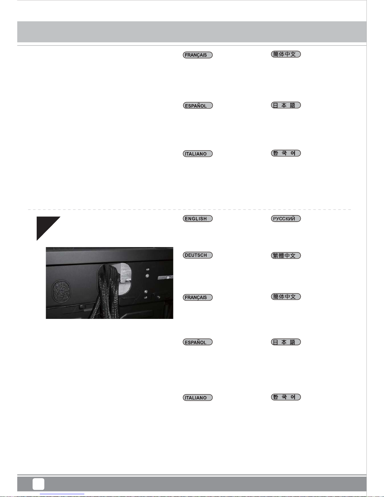
Route all power supply cables to
the opening on the left of the
power supply.
Проложите все кабели
питания через отверстие
слева от блока питания
모든 파워서플라이 케이블을
파워서플라이의 왼쪽 빈 공간에
정리해줍니다.
請將所有電源線穿過電源左邊
的開孔。
请将所有电源线穿过电源左边
的开孔。
全ての電源ケーブルを電源の
左上の開口部に通します。
Installation guide
11
Nous vous recommandons de
commencer à gérer l'organisation
des câbles maintenant comment
l'ATX 24pin, les connecteurs des
ports E/S de façade, et tout autre
connecteur des appareils du
panneau frontal.
Le recomendamos que
empiece a gestionar el enrutado
de cables ahora y conecte cables
como el ATX 24 pines, los
conectores frontales E/S y
cualquier otro conector de los
dispositivos del panel frontal.
Vi raccomandiamo di iniziare
subito la sistemazione delle
connessioni e collegare quindi
i connettori relativi ai cavi ATX
24pin, alle connessioni I/O frontali
e qualsiasi altro collegamento
delle periferiche poste
frontalmente.
이 단계에서부터 ATX 24핀,
전면 I/O 커넥터, 그리고 전면
패널에서의 다른 커넥터 등
케이블 정리를 하시기를
권장합니다.
我们建议您可以在此时开始理线,
请先安上ATX24Pin接线,Front
panel controller 与Front I/O。
この 時点でケーブ ル 取り回しを
考えながら、ATX24ピン、フロン
トI/ Oコネクタ、その他フロントパ
ネルデバイスからのコネクタ類の
ケーブルを接続するようお勧めし
ます。
Mammoth Series MM01
Page 15
14
15
Bauen Sie 3,5-Zoll-Festplatten
in die Laufwerkhalterung ein.
Installez les disques durs 3.5”
dans le casier.
Instale discos duros de 3,5”
en la carcasa para dispositivos
Installare gli hard drive da 3,5”
nel supporto.
Install 3.5” hard drives into the
drive cage.
Установите 3,5-дюймовые
жесткие диски в кронштейн
для жестких дисков.
3.5” 하드 드라이브를 드라이브
케이지에 설치합니다.
將3.5吋硬碟安裝至主硬碟架。
将3.5吋硬盘安装至主硬盘架。
ドライブケージに3. 5インチハー
ドドラ イブ を 装 着しま す。
Bauen Sie die Laufwerkhalterung
wieder das Gehäuse ein.
Achten Sie darauf, die Kabel
sauber zu verlegen.
Remettez le casier dans le
boîtier avec faisant cheminer
correctement les câbles.
Instale de nuevo la carcasa
para discos duros en la carcasa
con los cables enrutados.
Riposizionare il supporto nel
case con i cavi opportunamente
sistemati.
Install hard drive cage back
into the case with cables routed.
Установите кронштейн для
жестких дисков на место в
корпус с проложенными
кабелями.
하드 드라이브 케이지를
케이스에 넣은 후 케이블을
정리합니다.
將3.5吋主硬碟架裝回機殼,
同時請注意理線。
将3.5吋主硬盘架装回机壳,
同时请注意理线。
ケーブルを取り回しながら、
ハードドライブケージを元 に
戻します。
Installation guide
12
Mammoth Series MM01
Page 16

16
17
Dem Sie die Abdeckung der
5,25-Zoll-Laufwerkschächte ab,
installieren Sie die gewünschten
5,25-Zoll-Geräte.
Retirez les caches des baies
5.25” pour installer vos appareils.
Quite las cubiertas para bahía de
dispositivos de 5,25” para instalar
los dispositivos de 5,25”
necesarios.
Allentare le due viti sul lato
posteriore del telaio e poi
rimuovere il coperchio superiore.
Remove the 5.25” drive bay
covers to install required 5.25”
devices.
Снимите крыши отсеков для
5,25-дюймовых устройств и
установите необходимые
5,25-дюймовые устройства.
5.25”드라이브 베이 커버를
제거한 후 필요한 5.25” 장치를
설치합니다.
移除5.25吋檔板,
安裝上5.25吋裝置。
移除5.25吋文件板,
安装上5.25吋装置。
5.25インチドライブベイカバー
を外して、必要な5.25インチデ
バイスを装着します。
Schließen Sie sämtliche Kabel für
verwendete 5,25-, 3,5- und
2,5-Zoll-Laufwerke an.
Branchez tous les câbles pour
les lecteurs 5.25”, 3.5”, et 2.5”
selon vos besoins
Conecte todos los cables
necesarios para dispositivos
de 5,25”, 3,5” y 2,5”
Per installare le necessarie
periferiche da 5,25”, rimuovere
il cover del bay da 5,25”
Connect all cables for 5.25”, 3.5”,
and 2.5” drives as needed..
Подсоедините все кабели
5,25-дюймовых, 3,5-дюймовых и
2,5-дюймовых устройств
соответствующим образом.
5.25”, 3.5”, 2.5” 드라이브 의
모든 케이블을 필요한 만큼
연결한 후
先連接上所有磁碟需要用到的
線材(包含5.25吋、3.5吋以及
2.5吋)
先连接上所有磁盘需要用到的
线材(包含5.25吋、3.5吋以及
2.5吋)
必要に応じて5.25インチ、3.5
インチ、および2.5インチのドラ
イブ用のケーブル全部を接続。
Installation guide
13
Mammoth Series MM01
Page 17
18
Entfernen Sie
Steckplatzabdeckungen,
installieren Sie die gewünschten
Erweiterungskarten. Bei nicht
verwendeten Steckplätzen sollten
die Abdeckungen angebracht
bleiben.
Retirez les équerres pour
installer vos cartes d'extension.
Les emplacements inutilisés
doivent garder leur équerre.
Quite las cubiertas de los
zócalos de expansión para
instalar las tarjetas de expansión
necesarias. Los zócalos no
usados deberían tener cubiertas
instaladas.
Rimuovere i cover degli slot di
espansione per installare le
schede. Gli slot inusati dovrebbero
conservare i cover.
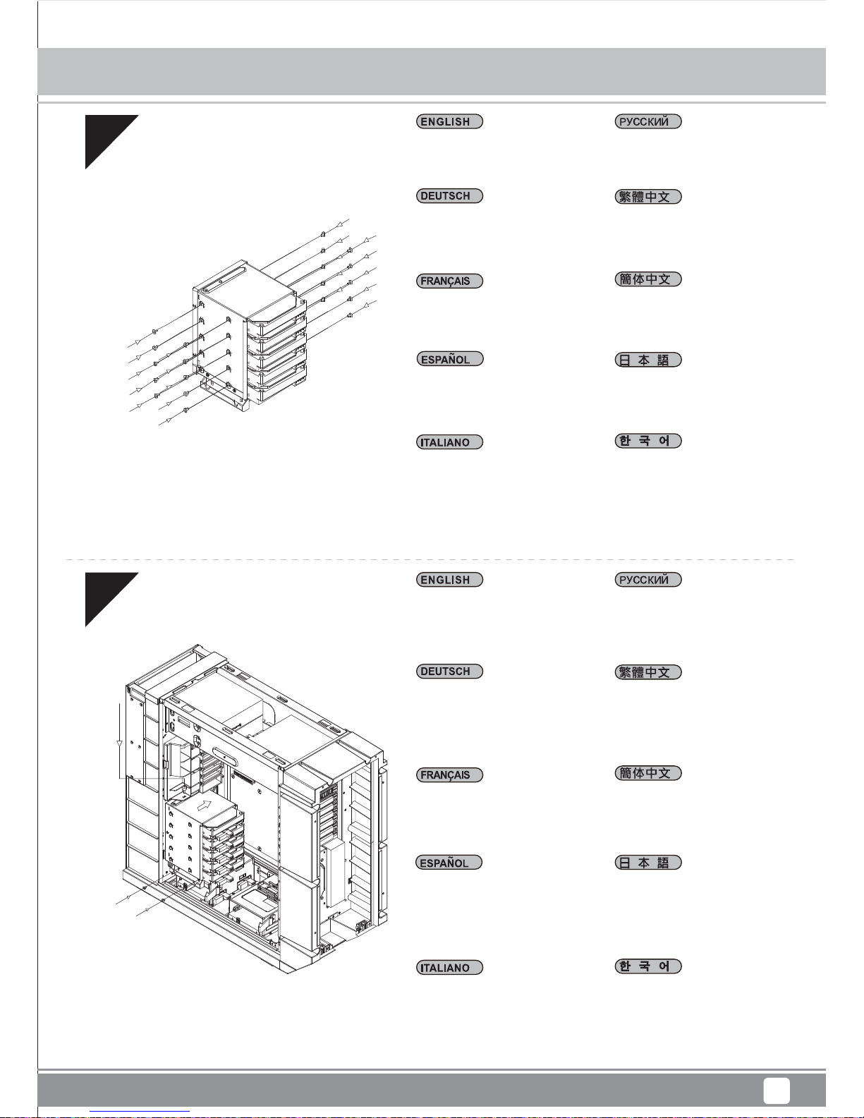
Remove expansion slot covers
to install required expansion
cards. Unused slots should
have covers installed.
Ослабьте два винта на
задней панели корпуса и
снимите верхнюю крышку.
확장슬롯 커버를 제거한 후,
필요한 확장카드를 설치 합니다.
사용되지 않은 슬롯의 슬롯
커버는 다시 설치 합니다.
移除擴充槽檔片並安裝擴充卡,
未使用的擴充槽請將檔片裝回
並以內附螺絲鎖固。
移除扩展槽档片并安装扩充卡,
未使用的扩展槽请将档片装回
并以内附螺丝锁固。
拡張スロットカバーを取り外して、
必要な拡張カードを装着します。
未使用のスロットにはカバーを
取り付けた ままにします。
Installation guide
14
Mammoth Series MM01
Page 18
19
20
Setzen Sie eine 3,5-ZollFestplatte in den unteren
Festplattenkäfig ein
Insérez le lecteur 3,5" dans
la cage du lecteur inférieur .
Inserte el disco duro de 3,5”
en la carcasa inferior para
discos duros.
Inserire il disco rigido 3.5” nel
cage unità inferiore.
Insert 3.5” hard drive into the
lower hard drive cage
Установите 3,5-дюймовый
жесткий диск в нижний отсек
для жестких дисков
3.5” 하드 드라이브를 하단 하
드 드라이브 케이지에 삽입하
십시오.
額外的3.5吋硬碟,請安裝於
底部硬碟架。
额外的3.5吋硬盘,请安装于
底部硬盘架。
一生懸命に3.5を挿入して」下部
のハードディスク・ケージに運転
します
Bauen Sie die obere
Abdeckung wieder ein.
Réinstallez le panneau
supérieur.
Reinstale el panel
superior
Reinstallare il pannello
superiore.
Reinstall the top panel.
Установите на место
верхнюю панель.
상부 패널을 재 설치 합니다.
裝回上蓋。
装回上盖。
上部パネルを元に戻します
Installation guide
15
Mammoth Series MM01
Page 19

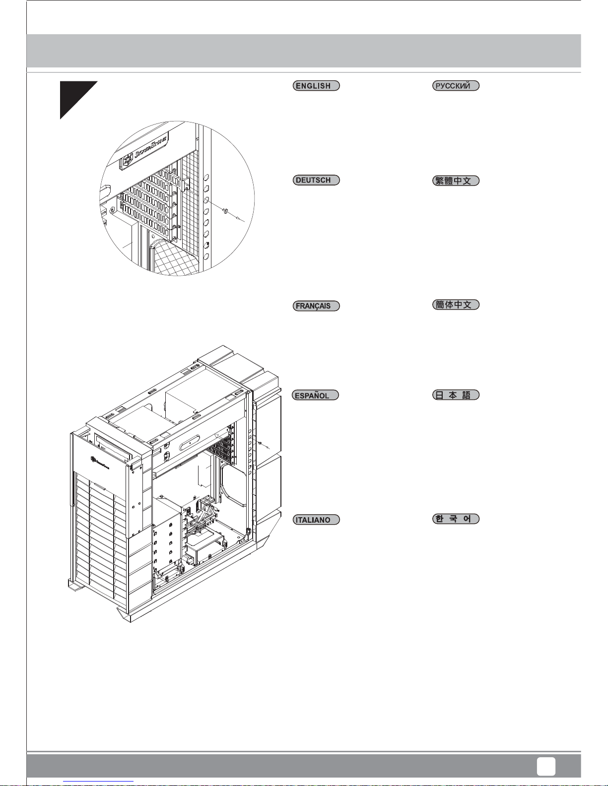
21
Installieren Sie zum Abschluss
der Installation die linke und
rechte Seitenwand wieder.
Réinstallez les deux panneaux
latéraux pour terminer le
montage.
Reinstale los paneles laterals
izquierdo y derecho para
completar la instalación.
Reinstallare entrambi i pannelli
laterali per completare
l’installazione..
Reinstall both left and right
side panel to complete
installation.
Для завершения установки
установите на место левую
и правую боковые панели.
왼쪽과 오른쪽 사이드 패널을
모두 재 설치해 설치를 마칩니
다.
裝回左右側板,完成組裝。
装回左右侧板,完成组装。
両方の左右パネルを元に戻す
と、インストールは 完了です。
Installation guide
16
Mammoth Series MM01
Page 20

(1) Front Panel Connector installation
Power switch and reset switch installation guide:
Please refer to the motherboard manuals for the motherboard’s “Front Panel Connector” or “System Panel Connector” pin definition.
Power switch and reset switch have no polarity, so they can be connected in any orientation.
Guida all’installazione dei connettori Power Switch e Reset Switch:
Fare riferimento al manuale della scheda madre nella sezione “Connettori del pannello frontale” o “Connettori del pannello di sistema”.
Power switch e reset switch non hanno polarità, posso essere pertanto connessi con qualsiasi orientamento.
파워 스위치 및 리셋 스위치 설치 가이드
메인보드 매뉴얼의 전면패널 커넥터 혹은 시스템패널 커넥터 핀을 참조하기 바랍니다. 파워 스위치와 리셋 스위치는 극성이 없어
어떤 방향으로 설치해도 무방합니다.
電源スイッチおよびリセットスイッチのインストールガイド:
マザーボードの「フロントパネルコネクタ」または「システムパネルコネクタ」のピン配列についてはマザーボードマニュアルを参照
してください。電源スイッチとリセットスイッチに極性はないので、いずれの方向でも接続できま。
Power Switch 與Reset Switch安裝說明:
請參考主機說明書的Front Panel Connectors安裝Pin Define,將Connector插上;Power Switch 與Reset Switch並無正負極性之分,
反插正插都不影響功能性。
Power Switch 与Reset Switch安装说明:
请参考主机说明书的Front Panel Connectors 安装Pin Define,将Connector插上;Power Switch与Reset Switch并无正负极性之分,
反插正插都不影响功能性。
Guide d'installation des interrupteurs d'allumage et de réinitialisation :
Veuillez-vous référer au manuel de votre carte mère pour la description des broches "des connecteurs du panneau frontal" et des broches
"des connecteurs du panneau système". Les interrupteurs d'allumage et de réinitialisation ne possède pas de polarité, donc ils peuvent être
branché dans les deux sens.
Guía de instalación de los interruptores de encendido y reseteo:
Por favor, consulte en los manuales de la placa base la configuración de pines del “Conector de panel frontal” ó “Conector de panel de
sistema”
de su placa base. Los interruptores de encendido y reseteo no tienen polaridad, luego se pueden conectar con cualquier orientación.
Инструкция по подключению выключателя питания и кнопки перезагрузки (reset):
Описание контактов разъемов приведены в разделах “Разъемы передней панели” или “Разъемы системной панели” руководства
пользователя материнской платы. Выключатель питания и кнопка перезагрузки не имеют полярности, поэтому их можно
подключать в любой ориентации
Ein-/Ausschalter und Rücksetztaste (Reset) installieren:
Bitte suchen Sie in der Motherboard-Dokumentation nach der Pinbelegung der Anschlüsse des Frontbedienfeldes („Front Panel
Connectors“oder „System Panel Connectors“). Ein-/Austaste und Rücksetztaste benötigen keine bestimmte Polarität, können daher
beliebig (ohne auf +und - zu achten) angeschlossen werden.
Connector definition
17
Mammoth Series MM01
Page 21

Connector definition
18
(1) Front Panel Connector installation
Please refer to the motherboard manuals for the motherboard’s “Front Panel Connector ” or “System Panel Connector” pin definition.;
the white/black wires are negative while other colors are positive wires. The Power LED wires are separate pins for compatibility with different
motherboard so please make sure they are connected in the right polarity by referring to your motherboard manual.
:
Bitte suchen Sie in der Motherboard-Dokumentation nach der Pinbelegung der Anschlüsse des Frontbedienfeldes („Front Panel Connectors
“ oder „ System Panel Connectors“). Die weißen/ schwarz Adern sind negativ (-), die farbigen Adern positiv (+).Die Kabel für die
Betriebsanzeige-LED sind zur Kompatibilität mit unterschiedlichsten Motherboards einzeln, nicht als kompletter Stecker ausgeführt. Achten
Sie hier bitte auf die richtige Polarität, lesen Sie in der Dokumentation Ihres Motherboards nach.
Veuillez-vous référer au manuel de votre carte mère pour la description des broches "des connecteurs du panneau frontal" et des broches
"des connecteurs du panneau système". Les câbles colorés en blanc/noir sont négatifs alors que ceux d'une autre couleur sont positifs. Les
câbles de la LED Power sont séparés afin d'être compatible avec différentes cartes mères, donc vérifiez bien qu'ils sont branchés avec la
bonne polarité en vous référant au manuel de votre carte mère
Por favor, consulte en los manuales de la placa base la configuración de pines del “Conector de panel frontal” ó “Conector de panel de
sistema” de su placa base. Los cables de color blanco/negro son negativos mientras que los de color son positivos. Los cables LED de
potencia tienen pines separados para compatibilidad con diferentes definiciones de pines de la placa base luego por favor, asegúrese de
que están conectados en la polaridad correcta consultando el manual de su placa base.
Fare riferimento al manuale della scheda madre nella sezione “Connettori del pannello frontale” o “Connettori del pannello di sistema”. I cavi
di colore bianco/nero sono il polo negativo, mentre quelli di colore diverso il positivo.
Описание контактов разъемов приведены в разделах “Разъемы передней панели” или “Разъемы системной панели” руководства
пользователя материнской платы. Белые/черный провода - отрицательной полярности, цветные провода - положительной
полярности. Провода светодиодного индикатора питания имеют отдельные контакты для совместимости с различными типами
контактов материнских плат, поэтому обратитесь к руководству пользователя материнской платы и убедитесь, что
полярность
соблюдена.
請參考主機說明書的Front Panel Connectors安裝Pin Define,將Connector插上; 白/黑色線的部分為負極,彩色線的部分是正極。Power LED
為了適應各主機板的不同, 特別設計為散Pin樣式,請安心使用。
请参考说明书的Front Panel Connectors安装Pin Define,将Connector插上;白/黑色线的部份为负极,彩色线的部份为正极。Power LED为了
适应主机板的不同, 特别设计为散Pin样式,请安心使用。
マザーボードの「フロントパネルコネクタ」または「システムパネルコネクタ」ピン配列についてはマザーボードマニュアルを参照してく
ださい。白/黑色のリード線はマイナスで、色の着いたリード線がプラスです。電源LEDリード線は種々のマザーボードピン定義と互換性を
持たせるため分離されたピンとなっているので、ご使用のマザーボードマニュアルを参照して、適切な極性に接続されるようお確かめくだ
さい。
메인보드 매뉴얼의 전면패널 커넥터 혹은 시스템패널 커넥터 핀을 참조하기 바랍니다. 하얀/검은선의 경우 음극이며, 다른 색의 경우
양극입니다. 파워 LED 선은 분리되어 다양한 메인보드에서 동작할 수 있도록 되어 있습니다. 그러므로 메인보드 매뉴얼을 참조하여
올바를 극성을 주의해 선택하시기 바랍니다.
Mammoth Series MM01
Page 22

(2) Front I/O connector guide
下表為Front I/O Connectors的Pin Define,請參閱主機板說明書的各Front I/O Connectors Pin Define一一核對。
MM01的Front I/O Connectors完全採用集合Pin方式以簡化安裝。
下表为Front I/O Connectors的Pin Define,请参阅主板说明书的各Front I/O Connectors Pin Define一一核对。
MM01的Front I/O Connectors完全采用集合Pin方式以简化安装。
以下はフロントI/Oコネクタピン配列ですが、お持ちのマザーボードのフロントI/Oピンヘッダは、マザーボードマニュアルをご参照ください。
MM01のI/Oコネクタは、インストールの容易なブロックタイプになっています。
아래는 전면 I/O 커넥터의 핀 사양입니다. 메인보드 매뉴얼을 참조해, 메인보드의 전면 I/O 핀사양을 재 확인한 후 설치합니다. MM01의 I/O
커넥터는 블록 타입으로 구성되어 있어 간편한 설치가 가능합니다.
Below are the front I/O connectors pin definition, please also check your motherboard manual to cross reference with
motherboard’s front I/O pin headers. MM01’s I/O connectors are in block type to simplify installation.
Nachstehend finden Sie die Pinbelegung der vorderen E/A-Anschlüsse; bitte gleichen Sie zudem das Handbuch Ihres Motherboards
mit den vorderen E/A-Pinzuweisungen ab. MM01 E/A-Anschlüsse befinden sich zur Vereinfachung der Installation in Blockart.
Au dessous de la description des broches des ports d'E/S, veuillez aussi vérifier sur le manuel de votre carte mère de
manière croisée que les broches sont correctement placées. Les connecteurs d'E/S de MM01 sont en bloc pour en simplifier
leur installation.
A continuación se detallan los pines para conectores E/S frontales, compruebe también por favor el manual de su placa base
para cotejar los pines E/S frontales de la misma. Los conectores E/S de MM01 son del tipo bloque para simplificar la
instalación.
Di seguito lo schema delle connessioni I/O frontali, confrontare lo schema con quanto riportato sul manuale della scheda
madre per effettuare un controllo incrociato. I connettori I/O MM01, per semplificare l’installazione, sono del tipo “a blocco”
Ниже приведено описание контактов передних разъемов ввода/вывода. Обратитесь также к руководству пользователя
материнской платы за описанием передних разъемов ввода/вывода типа "пин-хедер". Разъемы ввода/вывода "MM01" - блочного
типа, что облегчает сборку.
Connector definition
19
Mammoth Series MM01
Page 23

Component Size Limitations
20
(1) CPU cooler height limitation
The MM01 can accommodate all standard size components and even some that are out of spec, please
refer to the following guidelines for component selection and future upgrade considerations:
The height limit is 183mm and there is 13mm of clearance around the motherboard’s top edge.The clearance toward the front of the case is
variable depending on how much you fill the hard drive cage. There is 223mm of clearance from the end of an installed hard drive to the
motherboard minus a approximately 11mm for a 90 degree angled SATA connector (less room with 180 degree connectors). If you intend to fill
the drive cage, please install CPU fan on the rear side of the CPU cooler as shown in the photo illustration to avoid interference.
TDas Höhenlimit beträgt 183 mm, an der Oberkante des Motherboards verbleiben 13 mm Freiraum.
Der Freiraum zur Front des Gehäuses hin ist variabel und hängt davon ab, wie die Laufwerkhalterung gefüllt wurde. Zwischen dem Ende einer
installierten Festplatte und dem Motherboard verbleiben 223 mm Freiraum abzüglich etwa 11 mm bei um 90 ° abgewinkelten SATA-Verbindern
(bei 180 °-Verbindern bleibt weniger Platz frei). Wenn Sie die Laufwerkhalterung bestücken möchten, installieren Sie den CPU-Lüfter bitte an
der hinteren Seite des CPU-Kühlers (siehe Foto), damit es nicht zu Kollisionen kommt.
La hauteur maximale est de 183mm et il y a une espace de 13mm autour du bord supérieur de la carte mère.
L'espace vers l'avant du boîtier varie selon la façon dont vous avez remplie le casier à disques durs. Il y a un espace de 223mm entre le bord
des disques durs installés et de la carte mère moins approximativement 11mm pour un connecteur SATA à 90 degrés (encore moins d'espace
avec un connecteur standard à 180 degrés). Si vous essayez de remplir le casier à lecteurs, veuillez le ventilateur à l'arrière du dissipateur de
processeur comme montré sur l'illustration afin d'empêcher toutes interférences.
La altura límite es de 183mm y existe un espacio de 13mm alrededor del extremo superior de la placa base. El espacio hacia el frontal de la
carcasa es variable dependiendo de lo mucho que llene la carcasa para discos duros. Existe un espacio de 223mm hacia el final de un disco
duro instalado en la placa base menos unos 11mm para un conector SATA en ángulo de 90 grados (menos espacio con conectores de 180
grados) Si pretende llenar la carcasa para discos duros, por favor instale el ventilador para CPU en el lateral del disipador de la CPU como se
muestra en la foto para evitar interferencias.
Il limite in altezza è di 183mm e ci sono 13mm di tolleranza intorno al bordo superiore della scheda madre. La tolleranza verso la parte frontale
del case dipende da quanti hard drive sono installati nel supporto. Ci sono 223mm di tolleranza tra l’estremità di un hard drive installato e la
scheda madre meno approssimativamente 11mm di un connettore SATA a 90° (meno spazio con connettori a 180°). Se intendete riempire il
supporto hard drive, installate la ventola della CPU nella parte posteriore del dissipatore come mostrato in figura, per evitare interferenze.
Максимальная высота кулера – 183 мм, и зазор вокруг верхнего края материнской платы должен составлять 13 мм. Зазор до передней
панели корпуса зависит от количества устройств в кронштейне для жестких дисков. Зазор должен
составлять 223 мм от края
установленного жесткого диска до материнской платы минус приблизительно 11 мм для углового SATA-разъема (90 градусов) (с
плоскими разъемами (180 градусов) остается меньше места). Если предполагается полностью заполнить кронштейн для жестких
дисков, установите вентилятор ЦП на заднюю панель процессорного кулера, как показано на
Cooler限高是183mm,Cooler外缘允许超出主板上边界13mm。
Cooler前边界则需要视您需不需要安装大量硬盘,硬盘尾部距离主板后端有223mm,再扣除90度线材所需要最短的空间11mm。如果您购买的
主板CPU位置比较前面,建议您可以如图示把CPU风扇安装在Cooler后方,避免硬盘线材干扰扇叶。
高さ制限は183mmであり、マザーボード上の周囲に38mmの隙間があります。
ハードドライブケージに何台装着するかによって、ケース正面への距離は変わります。インストールされたハードドライブの終わりからマ
ザーボードまでから約11mm引くと、90度角のSATAコネクタ(180度コネクタより少ない空間)のために223mmの隙間があります。ドライブケー
ジに全装着するつもりであれば、干渉を避けるために、CPUファンを写真説明に示すようにCPUクーラーの後ろ側にインストールしてくださ
い。
높이는183mm로 제한되며, 메인보드의 상부 가장자리와13mm의 간격이 있습니다. 케이스 전면과의 여유 공간은 얼마나 많은 드라이브를
설치하는가에 따라 다릅니다. 설치된 드라이브로 부터 메인보드까지 약223mm의 여유 공간이 있고,90도 SATA 커넥터를 사용할 경우 11mm
가 줄어 듭니다. (일반180도 커넥터를 사용할 경우 이 공간은 더 줄어듭니다. ) 만약 드라이브 케이지를 다 채우게 될 경우 CPU쿨러의 팬을
그림에서와 같이 CPU쿨러의 뒷쪽에 장착하여 서로 간섭되는 것을 방지 합니다.
Cooler限高是183mm,Cooler外緣允許超出主機板上邊界13mm。
Cooler前邊界則需要視您需不需要安裝大量硬碟,硬碟尾部距離主機板後端有223mm,再扣除90度線材所需要最短的空間11mm。如果您購買的
主機板CPU位置比較前面,建議您可以如圖示把CPU風扇安裝在Cooler後方,避免硬碟線材干擾扇葉。
Mammoth Series MM01
Page 24

(2) Power supply and optical drive limitation
A: Length limitation
The Total length for power supply and optical drive: Power supply and the optical drive space in the MM01 share the same plane so the total
limit is 439mm including possible room for cables. We recommend maximum size for power supply of up to 220mm such as the SilverStone’s
ST1500. Maximum length limitation for PSU only is 285mm.
A: Ограничение на длину
Общая длина блока питания и приводов оптических дисков:
Блок питания и привод оптических дисков в корпусе MM01 расположены на одной панели, поэтому их общая длина не может
превышать 439 мм, включая возможное пространство для кабелей. Рекомендуется использовать блок питания длиной не более 220
мм, например модель SilverStone ST1500. Ограничение по
длине для блока питания составляет 285 мм.
A: Längenbeschränkung
Gesamtlänge Netzteil und optisches Laufwerk:
Netzteil und optisches Laufwerk liegen beim MM01 in derselben Ebene; daher stehen maximal 439 mm einschließlich Raum für Kabel zur
Verfügung. Wir empfehlen Netzteile mit einer maximalen Größe bis 220mm, z. B. das SilverStone ST1500.Das Netzteil darf nur maximal 285
mm lang sein.
A: Limitation de longueur
Longueur totale de l'alimentation et du lecteur :
Les logements pour l''alimentation et le lecteur optique partage le même plan dans le MM01 est dispose d'un longueur limite de 439mm en
incluant l'espace pour les câbles. Nous vous recommandons une taille maximale pour l'alimentation de 220mm comme la SilverStone
ST1500.La limite maximum de longueur de PSU est seulement de 285 mm.
A: Limitación de longitud
Longitud total de la fuente de alimentación y dispositivo óptico: El espacio de la fuente de alimentación y el dispositivo óptico en la MM01
comparten el mismo plano, luego el límite total es 439mm, incluyendo espacio posible para cables. Le recomendamos un tamaño máximo de
la fuente de alimentación de hasta 220mm, como la Silverstone ST1500. La limite maximum de longueur de PSU est seulement de 285 mm.
A: Limite in lunghezza
Lunghezza totale per alimentatore e drive ottico:
Lo spazio per l’alimentatore ed il drive ottico, nel case MM01, condividono lo stesso piano che ha una lunghezza totale di 439mm incluso lo
spazio per eventuali cavi. Vi raccomandiamo di scegliere alimentatori con lunghezza massima di 220mm come il SilverStone ST1500. La
limitazione della lunghezza massima solo per la PSU è di 285 mm.
A:長度限制
PSU與光碟機的總合限制:
MM01的電源供應器與光碟機相對,允許的總長度是439mm,需另外再扣除線材所需空間。
我們建議最大安裝到220mm長的電源供應器,例如銀欣ST1500電源。在不安裝光碟機單獨安裝電源供應器的情況下,電源長度限制是285mm。
A:長さ制限
電源および光学ドライブの全長:
電源と光学ドライブはMM01内で同じ面を共有した配置なので、ケーブルのための余裕を含んだ合計長さ限度は439mmです。電源に対し
ては、SilverStoneのST1500.などの最大サイズ220mmの電源が推薦されます。PSUのための最大の長さ制限は、285mmであるだけです。
A: 길이 제한
파워 서플라이와 광드라이브의 총 길이 제한.
파워서플라이와 광드라이브 는 MM01에 있어서 동일한 공간을 사용하며, 케이블에 필요한 여유공간을 감안하여 총 사용가능 길이는
439mm입니다. 파워 서플라이의 경우SilverStone의 ST1500와 같이 220mm 까지의 파워 서플라이 사용을 권장합니다. PSU만의 최대
길이 제한은 285mm입니다.
A:长度限制
PSU与光驱的总合限制:
MM01的电源供应器与光驱相对,允许的总长度是439mm,需另外再扣除线材所需空间。
我们建议最大安装到220mm长的电源供应器,例如银欣ST1500电源。在不安装光驱单独安装电源供应器的情况下,电源长度限制是285mm。
Component Size Limitations
21
Mammoth Series MM01
Page 25

Component Size Limitations
22
The absolute maximum length for optical drive is 225mm. Once the optical drive length surpasses 225mm, it will start to encroach the cable
routing hole to the right of the power supply compartment.
Die absolute Maximallänge von optischen Laufwerken liegt bei 225 mm. Überschreitet die Länge des optischen Laufwerks 225 mm, wird
dadurch die Kabelführungsöffnung rechts neben dem Netzteil beeinträchtigt.
La taille maximale des lecteurs optique est de 225mm. Si le lecteur optique dépasse les 225mm, il commencera à occuper l'espace destiné au
trou du compartiment de l'alimentation utilisé pour faire passer les câbles.
La longitud máxima absoluta para un dispositivo óptico es de 225mm. Una vez la longitud del dispositivo óptico sobrepasa los 225mm,
empezará a ocupar el espacio del agujero de enrutado a la derecha del compartimento de la fuente de alimentación
La lunghezza massima assoluta per il drive ottico è di 225mm. Una volta che il drive ottico supera i 225mm, inizierà ad interferire con il foro per
il cable routing disposto alla destra della zona dell’alimentatore.
Максимально допустимая длина привода оптических дисков составляет 225 мм. Если длина привода оптических дисков превышает
225 мм, он будет блокировать отверстие для прокладки кабелей в правой части отсека блока питания.
光碟機長度限制為225mm,若光碟機超過225mm,將會擋住電源左邊的背位理線孔。
光驱长度限制为225mm,若光驱超过225mm,将会挡住电源左边的背位理线孔。
光学ドライブのための最大絶対長は225mmです。光学ドライブ長が225mmを超えると、それは電源コンパートメント右へのケーブル通しホール
にカブり始め ます。
광드라이브를 위한 최대 공간은 225mm 입니다. 광드라이브가 225mm를 상회할 경우 파워 서플라이 오른쪽의 케이블 정리 공간과 간섭이
일어나기 시작합니다.
Mammoth Series MM01
Page 26

(2) Power supply and optical drive limitation
B: Power supply cable length recommendation
Below is the recommended cable length for retail ATX motherboards. If the cables are not long enough, please purchase extension cables.
B: Netzteilkabel – Längenempfehlungen:
Nachfolgend finden Sie die empfohlenen Kabellängen für handelsübliche ATX-Motherboards. Sind die Kabel zu kurz, kaufen Sie
Verlängerungskabel.
B: Recommandations de longueurs des câble de l'alimentation:
Ci-dessous est la longueur de câble recommandée pour les cartes mères ATX. Si les câbles ne sont pas assez long, veuillez acheter des
rallonges.
B: Recommandations de longueurs des câble de l'alimentation:
A continuación se encuentra la longitud de cable recomendada para placas base ATX. Si los cables no son lo bastante largos, por favor
compre cables de extensión.
B: Raccomandazioni per la lunghezza dei cavi dell’alimentatore:
Di seguito sono elencate le lunghezze raccomandate dei cavi d’alimentazione per le schede madre ATX vendute al dettaglio. Acquistare
delle prolunghe qualora i cavi non fossero sufficientemente lunghi.
B: Рекомендации по длине кабелей блока питания
Ниже приведены рекомендации по длине кабелей для самостоятельно приобретаемых системных плат ATX. Если длина кабелей
недостаточна, приобретите удлинительные кабели.
B:電源線材建議長度:
以下是以一般市售ATX主機板抓出來的各線材建議長度列表,請先確認電源線長度是否足夠如果不夠,請選購所需要的延長線。
B:电源线材建议长度:
以下是以一般市售ATX主板抓出来的各线材建议长度列表,请先确认电源线长度是否足够如果不够,请选购所需要的延长线。
B:電源ケーブル推奨長さ
下図はリテールATXマザーボード用のケーブル推奨長さです。ケーブル長が不十分の場合は、延長ケーブルをご購入ください。
B:파워 서플라이 케이블 길이 및 권장사항
다음은 소매 ATX 메인보드용 권장 케이블 길이입니다. 케이블이 충분히 길지 않을 경웅 연장 케이블을 구매하십시오.
Component Size Limitations
23
Cable type and location
EPS 8pin/ATX4pin (from left side of PSU)
ATX 24Pin (from left side of PSU)
SATA 15Pin (from left side of PSU to top opticaldrive)
SATA 15Pin (from left side of PSU to bottom most3.5” hard drive)
SATA 15Pin (from left side of PSU to 2.5” harddrive)
PCIE 8/6pin (to first expansion slot)
Minimum length
530mm
300mm
50mm
430mm
600mm
380mm
Mammoth Series MM01
Page 27

Component Size Limitations
24
When using a non-modular PSU with a depth of 140mm, route the CPU 8/4 Pin through the indicated hole first. PP07 extension cables can be
used if the cable is not long enough
Bei Einsatz eines nicht-modularen Netzteils mit einer Tiefe von 140 mm führen Sie zunächst den CPU-Anschluss 8/4 durch die angezeigte
Bohrung. Ist das Kabel zu kurz, können Sie ein PP07-Verlängerungskabel verwenden.
Quand vous utilisez un PSU non-modulaire d'une profondeur de 140 mm, placez d'abord la broche 8/4 du CPU à travers le trou indiqué. Des
câbles d'extension PP07 peuvent être utilisés si le câble n'est pas assez long.
Cuando se usa una FA no modular con una profundidad de 140mm, primero enrute los 8/4 pines de la CPU a través del agujero indicado. Los
cables de extensión PP07 se pueden usar si el cable no es lo bastante largo.
如果您使用非模組化的電源供應器,電源深度為140mm。 CPU 8/4 Pin線材請優先由這個小洞穿過,這是最短的走線距離。如果您的線材長度還
是不足,建議您可以選購銀欣PP07延長線加以延長。
如果您使用非模块化的电源供应器,电源深度为140mm。 CPU 8/4 Pin线材请优先由这个小洞穿过,这是最短的走线距离。如果您的线材长度还
是不足,建议您可以选购银欣PP07延长线加以延长。
奥行き140mmの非モジュール式PSUを使用する場合、CPU 8/4ピンを表示された孔に通してください。ケーブル長が不足している場合は、PP07延
長ケーブルが利用できます。
깊이가 140mm인 비모듈식 PSU를 사용하는 경우, 먼저 CPU 8/4 핀을 표시된 구멍을 통과시키십시오. 케이블의 길이가 충분히 길지 않을
경우 확장 케이블 PP07을 사용할 수 있습니다.
При использовании немодульного блока питания с глубиной 140 мм сначала пропустите разъем процессора 8/4 через показанное
отверстие. Если длина кабеля окажется недостаточной, в корпусе PP07 можно использовать удлинительные кабели.
Quando si usa una PSU non modulare con una profondità di 140 mm, prima infilare nel foro indicato i pin 8/4 della CPU. Se il cavo non è
sufficientemente lungo, possono essere usati cavi di prolunga PP07.
Mammoth Series MM01
Page 28

(3) Graphics card/expansion card length limitation
MM01 can support 13.3”(338mm) consumer level graphics cards.
Das MM01 nimmt bis zu 338 mm lange Grafikkarten auf.
Le MM01 est compatible avec les cartes graphiques de 13.3” ou 338 mm.
La MM01 puede aceptar tarjetas gráficas de hasta 13,3” (338mm).
MM01 può supportare schede grafiche con una lunghezza massima di 13,3” (338mm).
MM01 поддерживает графические карты потребительского уровня размером 13,3 дюйма (338 мм)
MM01支援到PCIE規格定義的上限長度為13.3”的顯示卡。
如果您還是有安裝不下的顯示卡,請與我們聯繫,並告知我們顯示卡的廠牌與型號,由我們協助您後續安裝事宜。
MM01支持到PCIE规格定义的上限长度为13.3”的显卡。
如果您还是有安装不下的显卡,请与我们联系,并告知我们显卡的厂牌与型号,由我们协助您后续安装事宜。
MM01は13.3インチ(338mm)の市販グラフィックカードをサポートできます。
MM01은 최대 13.3”(338mm)의 그래픽 카드를 지원합니다.
Component Size Limitations
Mammoth Series MM01
25
Page 29

Component Size Limitations
26
There is 61mm of distance between the motherboard to the hard drive. If you use a memory similar to the one shown in the illustration, please
remove the heatsink on it prior to installation.
Zwischen Motherboard und Festplatte verbleiben 61 mm Platz. Sofern Sie Speichermodule verwenden, die dem Modul in der Illustration
ähneln, entfernen Sie vor der Installation den Kühlkörper.
Il y a une distance de 61mm entre la carte mère et les disques durs. Si vous avez des barrettes mémoires similaires à celles montrées dans
l'illustration, veuillez démonter les dissipateurs avant de les installer.
Existe una distancia de 61mm desde la placa base hasta el disco duro. Si usa una memoria similar a la que se muestra en la ilustración, quite
por favor el radiador antes de la instalación
Ci sono 61mm di distanza tra la scheda madre e l’hard drive. Se utilizzate memorie simili a quelle mostrate in foto, rimuovete il dissipatore
superiore prima dell’installazione.
Расстояние между материнской платой и жестким диском должно составлять 61 мм. При использовании модуля памяти, аналогичного
показанному на рисунке перед установкой снимите с него радиатор.
從主機板表面至硬碟的距離有61mm ,視您的主機板而定。主硬碟架上的硬碟有可能會檔在記憶體上方,如果你有如類似下圖的記憶體,請移除
上面的散熱片部分。
从主机板表面至硬盘的距离有61mm ,视您的主机板而定。主硬盘架上的硬盘有可能会档在记忆体上方,如果你有如类似下图的记忆体,请移
除上面的散热片部分。
マザーボードからハードドライブまでは61mmの距離があります。図示されたものに類似したメモリを使う場合、装着に先がけてそれの上のヒート
シンクを 取り外してください 。
메인보드에서 하드 드라이브까지 61mm의 공간 여유가 있습니다. 아래 그림과 유사한 메모리를 사용할 경우 설치 전에 히트싱크를
제거하시기 바랍니다.
(4) Memory height limitation
Mammoth Series MM01
Page 30

(5) Motherboard size limitation
MM01 supports up to SSI-EEB (Extended ATX motherboard). New generation of SSI-CEB server or workstation motherboards no longer
require CPU cooler mounting holes on the motherboard tray. Coolers can now be installed directly on the motherboard. As a result, we
eliminated support for SSI-CEB CPU cooler mounting holes and instead increased the large gap on the motherboard tray to support CPU
cooler back plates swapping with more LGA 1150/1155 motherboards. The MM01 chassis’ support for new and future SSI-CEB motherboards
should be unaffected by this change.
Note: MM01 has standard screw hole for motherboards and does not include additional screw hole that some server motherboards require.
MM01 unterstützt maximal SSI-EEB (Extended-ATX-Motherboard). Hochmoderne Motherboards von SSI-CEB-Servern und -Arbeitsrechnern
benötigen keine Löcher zur CPU-Kühlermontage am Motherboard-Einschub mehr. Die Kühler können nun direkt am Motherboard installiert
werden. Dadurch haben wir die Unterstützung der Löcher zur SSI-CEB-CPU-Kühlermontage aufgegeben und stattdessen den Abstand am
Motherboard-Einschub vergrößert; dadurch werden CPU-Kühlerrückplatten unterstützt, die mit einer größeren Anzahl an LGA 1150-/1155Motherboards kompatibel sind. Die Unterstützung neuer und zukünftiger SSI-CEB-Motherboards durch das MM01-Gehäuse wird durch diese
Änderung nicht beeinflusst.
Hinweis: Das MM01 hat ein Standardschraubenloch für Motherboards; es verfügt über kein zusätzliches Schraubenloch, das einige
Server-Motherboards benötigen.
MM01 supporte jusqu'à SSI EEB-(carte mète Extended ATX). Les portes-carte mère destinés à la nouvelle génération de cartes mères pour
station de travail ou serveur SSI-CEB n'ont plus besoin de trous de montage pour le refroidisseur de l'unité centrale. Les refroidisseurs
peuvent désormais s'installer directement sur la carte mère. Nous avons ainsi éliminé le support destiné aux trous de montage pour le
refroidisseur de l'unité centrale SSI-CEB. L'espace sur le porte-carte mère permettant de permuter les plaques arrière du refroidisseur, avec
plus de cartes mères LGA 1150/1155, est agrandi. Le support du châssis MM01 pour les nouvelles cartes mères SSI-CEB et celles à venir,
ne sera pas affecté par cette modification.
Note : MM01 a un trou de vis standard pour les cartes mères et n'inclut pas de trou de vis supplémentaire que certains serveurs de carte-mère
demandent.
La MM01 acepta hasta SSI-EEB (Placa base ATX Extendida). a nueva generación de servidores SSI-CEB ó placas base para estaciones de
trabajo ya no precisan de agujeros de montaje en la bandeja de la placa base para el disipador de la CPU. Ahora puede instalar los
disipadores directamente sobre la placa base. Como resultado, eliminamos los agujeros de montaje para disipadores SSI-CEB de la CPU y
en cambio aumentamos el gran hueco en la bandeja de la placa base para así poder aceptar el cambio de placas traseras para CPU con más
placas base LGA 1150/1155. La compatibilidad del chasis de la MM01 con placas base SSI-CEB nuevas y futuras no debería verse afectada
con este cambio.
Nota: La FT04 tiene un agujero de tornillo estándar para placas bases y no incluye un agujero para tornillo adicional que algunas placas base
para servidor precisan.
MM01 supporta schede madre SSI-EEB (ATX estesa). La nuova generazione di schede madri per server o workstation in formato SSI-CEB
non richiede più i fori di montaggio dei dissipatori sui supporti delle mainboard stesse. I cooler possono essere ora montati direttamente sulla
scheda madre. In conseguenza di ciò sono stati eliminati i fori specifici ed è stata ricavata un’apertura di maggiori dimensioni nel supporto
della motherboard. Questo ha permesso di aumentare l’accessibilità al back plate della CPU in un maggior numero di schede basate su
socket LGA 1150/1155. Il supporto alle nuove e future motherboard SSI-CEB non è e non sarà influenzato da questo cambiamento.
Nota: MM01 ha un foro standard per le schede madri e non include altri fori richiesti per alcune schede madre server.
Component Size Limitations
27
Mammoth Series MM01
Page 31

Component Size Limitations
28
MM01 supporta schede madre SSI-EEB (ATX estesa). La nuova generazione di schede madri per server o workstation in formato SSI-CEB
non richiede più i fori di montaggio dei dissipatori sui supporti delle mainboard stesse. I cooler possono essere ora montati direttamente sulla
scheda madre. In conseguenza di ciò sono stati eliminati i fori specifici ed è stata ricavata un’apertura di maggiori dimensioni nel supporto
della motherboard. Questo ha permesso di aumentare l’accessibilità al back plate della CPU in un maggior numero di schede basate su
socket LGA 1150/1155. Il supporto alle nuove e future motherboard SSI-CEB non è e non sarà influenzato da questo cambiamento.
Nota: MM01 ha un foro standard per le schede madri e non include altri fori richiesti per alcune schede madre server.
MM01最大支援至SSI-EEB(俗稱E-ATX)規格主機板。新一代SSI-CEB規格伺服器主機板,已經沒有依照SSI規範的Xeon Cooler在機殼上的鎖固孔
位,其Cooler本身是鎖在主機板上。我們新一代的機殼為了配合LGA1150/1155的位置,將主機板底板對應的開孔加大,因而取消了SSI規範上
的Cooler鎖固螺柱。並不是不相容於SSI CEB主機板,只是因應主機板規格的演進而修改設計。須請您注意的是,許多伺服器主機板可能會有
多增加一些非標準的鎖固孔位。
MM01只會有規範上應該有的鎖固孔位。
MM01最大支持至SSI-EEB(俗称E-ATX)规格主板。新一代SSI-CEB规格服务器主板,已经没有依照SSI规范的Xeon Cooler在机壳上的锁固孔位,
其Cooler本身是锁在主板上。我们新一代的机壳为了配合LGA1150/1155的位置,将主板底板对应的开孔加大,因而取消了SSI规范上的Cooler
锁固螺柱。并不是不兼容于SSI CEB主板,只是因应主板规格的演进而修改设计。须请您注意的是,许多服务器主板可能会有多增加一些非标
准的锁固孔位。
MM01只会有规范上应该有的锁固孔位。
MM01はSSI-EEB(拡張ATXマザーボード)までサポートしています。新世代のSSI-CEBサーバまたはワークステーションマザーボードは、
マザーボードトレイ上のCPUクーラー設置孔をもはや必要としていません。クーラーは現在直接マザーボードに装着できます。結果として
、弊社はSSI-CEBCPUクーラー設置孔サポートをやめ、代わりに、より多くのLGA1150/1155マザーボードと互換性のあるCPUクーラー後
部プレートをサポートするため、マザーボードトレイ上のギャップをより増大させました。この変更は、FT04ケースの新しい、将来の
SSI-CEBマザーボードへのサポートには影響しません。
注:MM01はマザーボードのために標準的なネジ穴を持って、何枚かのサーバー・マザーボードが必要とする更なるネジ・ホールを含みま
せん。
MM01은 SSI-EEB(Extended ATX 메인보드)까지 지원합니다. SSI-CEB 서버나 워크스테이션은 더이상 메인보드 트레에에 CPU 쿨러
마운팅 홀을 필요로 하지 않습니다. 쿨러가 메인보드에 직접 장착이 가능하고, 그 결과 SSI-CEB 쿨러 마운팅 홀을 제거 했으며, 메인보드
트레이에 큰 공간을 두어 LGA1150/1155 을 지원하는 보다 많은 메인보드 CPU 쿨러 백플레이트를 지원 할 수 있게 하였습니다. 이런
변화들은 SSI-CEB 메인보드 신제품 혹은 미래에 출시될 제품을 지원하는데 영향이 없을 것입니다.
참고: MM01에는 메인보드를 고정하기 위한 표준 나사 구멍이 있으나, 일부 서버 메인보드에 필요한 추가 나사 구멍은 없습니다.
Mammoth Series MM01
Page 32

(1) : CPU Cooler Supporter
a. First set the chassis on its side, make sure it is on a level surface.
b. The CPU supporter has already been installed in a commonly used position. You can loosen the screw in the middle to fully extend it.
c. If the supporter position is not optimal for your setup, remove two more screws on left and right side to move the supporter. After finding the
optimal position for your setup, secure with screws.
d.Move the supporter arm up to touch the installed CPU cooler and then secure the middle screw.
e. Place the chassis upright to let the CPU cooler rest naturally on the supporter.
f. Recommended usage range for supporter:
From 13mm beyond edge of the motherboard to 45mm inward from the motherboard edge.
Most 120mm fan based tower-style CPU cooler should be compatible.
a. Legen Sie das Gehäuse zunächst auf die Seite, achten Sie auf einen ebenen Untergrund.
b. Falls sich die Halterposition nicht für Ihren Bedarf eignen sollte, entfernen Sie zum Verschieben des Halters zwei weitere Schrauben auf
der linken und rechten Seite. Nachdem Sie die optimale Position gefunden haben, wieder mit den Schrauben fixieren.
c. Falls sich die Halterposition nicht für Ihren Bedarf eignen sollte, entfernen Sie zum Verschieben des Halters zwei weitere Schrauben auf
der linken und rechten Seite. Nachdem Sie die optimale Position gefunden haben, wieder mit den Schrauben fixieren.
d. Bewegen Sie den Halterarm nach oben, bis er den installierten CPU-Kühler berührt; anschließend mit der mittleren Schraube fixieren.
e. Stellen Sie das Gehäuse wieder aufrecht, damit der CPU-Kühler auf dem Halter zu liegen kommt.
f. Empfohlener Halter-Einsatzbereich:
Von 13 mm jenseits der Motherboard-Kante bis 45 mm von der Motherboard-Kante einwärts.
Die meisten CPU-Tower-Kühler mit 120 mm-Lüfter sollten passen.
a. Premièrement mettez le boîtier sur le côté, vérifiez bien qu'il soit bien à plat
b. Le support intégré du processeur a déjà été installé dans une position couramment utilisé. Vous pouvez desserrer la vis du milieu pour
l'étendre complètement.
c. Si la position du support n'est pas optimale pour votre configuration, retirez deux vis supplémentaires sur les côtés gauche et droit pour
bougez le support. Après avoir trouvé la position optimale pour votre configuration, fixez les vis.
d. Poussez le bras du support pour toucher le dissipateur de processeur installé et ensuite fixez la vais du milieu.
e. Remettez le boîtier debout pour laisser le dissipateur du processeur s'appuyer naturellement sur le support.
f. Intervalle recommandé pour le support:
De au delà de 13mm du bord de la carte mère à 45mm à l'intérieur du bord de la carte mère.
La plupart des dissipateurs de type tour équipé d'un ventilateur de 120mm doivent être compatible.
CPU And Graphic Gard Supporter
29
abc
d
ef
Mammoth Series MM01
Page 33

CPU And Graphic Card Supporter
30
a.請先翻倒機殼,維持機殼平躺。
b.CPU Cooler支撐架已經預先安裝在適當的位置,請先鬆開前面的螺絲,把支撐架展開。
c.如果支撐架的位置不適當,請再移除中間螺絲;將支撐架前後移動至適當位置再鎖固。
d.將支撐架展開至剛好接觸到CPU Cooler本體部分的下邊緣,然後鎖固中間的螺絲。
e.直立起機殼,Cooler會自然的躺在支架上。
f.支撐架的適用範圍:板外13mm ~ 板內45mm 請斟酌使用。我們建議您使用在120mm以上風扇規格的塔型Cooler
a.请先翻倒机壳,维持机壳平躺。
b.CPU Cooler支撑架已经预安装在适当的位置,请先松开前面的螺丝,把支撑架展开。
c.如果支撑架的位置不适当,请再移除中间螺丝;将支撑架前后移动至适当位置再锁固。
d.将支撑架展开至刚好接触到CPU Cooler本体部分的下边缘,然后锁固中间的螺丝。
e.直立起机壳,Cooler会自然的躺在支架上。
f.支撑架的适用范围:板外13mm ~ 板内45mm 请斟酌使用。我们建议您使用在120mm以上风扇规格的塔型Cooler
a.まず、側面を下にしてケースを置き、水平面にあるのを確かめます
b.CPUサポーターは一般的に使われる位置にインストール済みです。完全にそれを拡張するには、中間のネジを緩めます。
c.サポーター位置がセットアップのために最適でないならばサポーターを移動するため左右のネジ2本を外します。セットアップのため
に最適の位置を見つけたら、ネジで固定します。
d.サポーターアームが、インストールされたCPUクーラーに触れるよう移動させ、それから中間のネジを固定します。
e.CPUクーラーが自然にサポーターに載るよう、ケースを立てて置きます。
f.サポーターのための推奨使用範囲:
マザーボード縁を13mm越えた位置からマザーボード縁から内側45mmまで。
大部分のタワースタイルCPUクーラー付属の120mmファンは互換性があります。
a. 케이스를 옆으로 놓은 후에 평평하게 놓여 있는지 확인합니다.
b. CPU 서포터는 가장 많이 쓰이는 위치에 이미 장착되어 있습니다. 가운데 있는 나사를 풀어 늘릴 수 있습니다.
c. 서포터의 위치가 적절하지 않다면, 왼쪽과 오른쪽에 있는 두개의 나사를 더 풀어 서포터를 움직입니다. 적절한 위치를 찾은 후, 나사로
고정시킵니다.
d. 서포터 암을 움직여 설치된 CPU 쿨러에 닿도록 하고 중간 나사를 조여 고정시킵니다.
e. 케이스를 바로 세운 후, CPU 쿨러가 서포터에 자연스럽게 닿도록 합니다.
f. 서포터 사용 권장 범위
메인보드 끝 13mm에서 안쪽을 45mm 까지, 대부분의 120mm 팬 방식의 타워형태 CPU쿨러와 호환됨.
a. Per prima cosa disporre il cabinet su un fianco, possibilmente su una superficie piana.
b. Il supporto per il dissipatore è già installato nel case in una posizione standard. Potete allentare le viti al centro per estenderlo
completamente.
c. Se il supporto non si trova in posizione ottimale per il vostro setup, rimuovere due ulteriori viti a destra ed a sinistra per posizionare il
supporto stesso. Dopo aver trovato la corretta posizione per il vostro setup, avvitare nuovamente le viti.
d. Spostare il braccio del supporto verso l’alto fino a toccare il dissipatore per CPU installato, quindi avvitare le viti al centro.
e. imettere in piedi il cabinet, il dissipatore CPU si appoggerà in modo naturale sul supporto.
f. Range di utilizzo del supporto:
Da 13mm oltre il bordo della scheda madre a 45mm verso l’interno del bordo stesso.
La maggior parte dei dissipatori a torre con ventola da 120mm dovrebbero essere perfettamente compatibili.
a. (Сначала положите корпус набок на ровную поверхность.
b. Опора процессорного кулера уже установлена в обычном положении. Можно ослабить винты в центре, чтобы полностью
выдвинуть ее.
c. Если положение опоры не соответствует необходимой конфигурации, для перемещения опоры отвинтите еще два винта слева и
справа. Подобрав оптимальное
положение, для необходимой конфигурации затяните винты.
d. Переместите рычаг опоры вверх до соприкосновения с установленным процессорным кулером, а затем закрепите средний винт.
e. Установите корпус в вертикальное положение, чтобы процессорный кулер лежал на опоре.
f. Ниже приведены рекомендуемые положения опоры.
От 13 мм наружу от края материнской платы до 45 мм внутрь от края
материнской платы. Большинство процессорных кулеров со
120-мм вентиляторами башенного типа совместимы с данной опорой.
a. Primero tumbe la carcasa de lado, asegúrese de que está en una superficie lisa.
b. El soporte de la CPU ya ha sido instalado en una posición de uso corriente. Puede aflojar el tornillo medio para extenderlo por completo.
c. Si la posición del soporte no es óptima para su configuración, quite dos tornillos más de la izquierda y la derecha para mover el soporte.
Tras encontrar la posición óptima para su configuración, fíjela con tornillos.
d. Mueve el brazo soporte hasta tocar el disipador de CPU instalado y fije el tornillo medio
e. Ponga el chasis derecho para dejar que el disipador de la CPU descanse de forma natural en el soportef. Rango de uso recomendado f.
f. para el soporte:
Desde 13mm más allá del borde de la placa base hasta 45mm hacia el interior del borde de la placa base. La mayoría de los ventiladores
de 120mm para disipador de CPU estilo torre deberían ser compatibles.
Mammoth Series MM01
Page 34

a. Legen Sie das Gehäuse zunächst auf die Seite, achten Sie auf einen ebenen Untergrund.
b. Installieren Sie den VGA-Träger am Gehäuse; richten Sie ihn so aus, dass er die Netzanschlüsse an der Grafikkarte nicht blockiert.
c. Installieren Sie entsprechend dem verwendeten Steckplatz Klemmen am VGA-Träger.
Hinweis: Bei Installation mehrerer Grafikkarten dürfen Sie diese nicht nebeneinander installieren, da die Klemme nicht zwischen zwei
benachbarte Grafikkarte passt.
a. Premièrement mettez le boîtier sur le côté, vérifiez bien qu'il soit bien à plat
b. Installez le preneur en charge VGA sur le boîtier et réglez-le de façon à éviter les connecteurs électriques de la carte graphique.
c. Installez les clips du preneur en charge VGA en fonction de la fente installée.
Note : Si plus d'une carte graphique est installée, évitez de les installer en position adjacente l'une de l'autre car le clip peut ne pas s'insérer
entre deux cartes graphiques adjacentes.
a. Primero tumbe la carcasa de lado, asegúrese de que está en una superficie lisa.
b. Instale el soporte VGA en el chasis y ajústelo para evitar conectores de potencia en la tarjeta gráfica.
c. Instale los clips en el soporte VGA según el zócalo que se use.
Nota: si se instala más de una tarjeta gráfica, evite ponerlas una junto a la otra, ya que el enganche podría no encajar entre dos tarjetas
gráficas adyacentes.
a. Per prima cosa disporre il cabinet su un fianco, possibilmente su una superficie piana.
b. Installare il supporto VGA sul telaio e regolarlo per evitare i connettori d’alimentazione sulla scheda video.
c. Installare i fermagli sul supporto VGA in base all’alloggio installato.
Nota: Se è installata più di una scheda video, evitare di installarle una a fianco dell’altra, diversamente i fermagli potrebbero non essere
installati tra due schede video adiacenti.
a. Сначала положите корпус набок на ровную поверхность.
b. Установите планку порта VGA в корпус таким образом, чтобы не допустить соприкосновения с разъемами питания на графической
карте.
c. Установите фиксаторы на планку порта VGA в соответствии с установленным слотом.
Примечание. Если устанавливается
более одной графической карты, не устанавливайте их рядом, так как фиксатор может не
поместиться между двумя соседними графическими картами.
(2): Graphic card supporter
a. First set the chassis on its side, make sure it is on a level surface.
b. Install VGA supporter onto the chassis and adjust it to avoid power connectors on the graphic card.
c. Install clips onto the VGA supporter according to the installed slot.
Note: if more than one graphic card is installed, avoid installing them adjacent to each other as the clip may not fit between two adjacent
graphic cards.
ab c
CPU And Graphic Card Supporter
31
Mammoth Series MM01
Page 35

CPU And Graphic Card Supporter
32
a.請先翻倒機殼,維持機殼平躺。
b.將顯示卡支撐架鎖上機殼,可前後調整至不擋住顯卡電源插頭的位置。
c.視顯示卡槽位而定,鎖上支撐架的掛鉤。
注意:如果有多卡安裝時,不要讓顯示卡相鄰安裝,掛勾無法伸入兩張卡之間的縫隙。
a.请先翻倒机壳,维持机壳平躺。
b.将显卡支撑架锁上机壳,可前后调整至不挡住显卡电源插头的位置。
c.视显卡槽位而定,锁上支撑架的挂钩。
注意:如果有多卡安装时,不要让显示适配器相邻安装,挂勾无法伸入两张卡之间的缝隙。
a.まず、側面を下にしてケースを置き、水平面にあるのを確かめます
b.VGAサポーターをシャシー上にインストールして、それがグラフィック・カードの上で電力コネクターを避けるように調整してくださ。
c.装置されたスロットによってクリップをVGAサポーター上にインストールしてください。
注:複数のグラフィック・カードが設置されるならば、クリップが2枚の隣接したグラフィック・カードの間で合わないかもしれないので、
互いに隣接して彼らを就任させることを避けてください。
a. 케이스를 옆으로 놓은 후에 평평하게 놓여 있는지 확인합니다.
b. 섀시에 VGA 지지대를 설치하고 그래픽 카드에 있는 전원 커넥터를 방해하지 않도록 조정하십시오.
c. 설치된 슬롯에 따라 VGA 지지대에 클립을 설치하십시오.
참고: 2개 이상의 그래픽 카드가 설치된 경우, 클립이 인접한 2개의 그래픽 사이에 들어가지 못할 수 있기 때문에 2개의 그래픽 카드를 서로
인접하게 설치하지 마십시오.
Mammoth Series MM01
Page 36

(2) Graphics Card
When choosing a graphics card, we recommend models that have fan blowing exhaust air to the rear slot, this will ensure smooth and
efficient airflow within the MM01 for maximum cooling performance.
Bei der Auswahl von Grafikkarten empfehlen wir Modelle, die warme Luft über eine Öffnung im hinteren Teil des Steckplatzes in die
Außenwelt ableiten; dies gewährleistet eine ungestörte und wirksame Luftzirkulation innerhalb des MM01 und sorgt für eine optimale
Kühlung.
(1) CPU Cooler
If you are installing a tower-style CPU cooler, we recommend that the CPU fan blows rearward to work with MM01’s overall airflow.
Falls Sie einen tower-artigen CPU-Kühler installieren, empfehlen wir, den CPU-Lüfter die Luft nach hinten blasen zu lassen, damit er mit der
gesamten Luftbewegung im MM01 zusammenarbeitet.
Si vous installez un dissipateur de processeur de type "tour", nous vous recommandons que le ventilateur du dissipateur souffle vers l'arrière
pour fonctionner dans le même sens que le flux d'air généré par le MM01 lui-même.
Si está instalando un disipador de CPU para torre, le recomendamos que el ventilador de la CPU ventile hacia trasera para estar en
concordancia con el flujo de aire global de la MM01.
Se scegliete un dissipatore a torre, assicuratevi che il flusso d’aria della ventola sia disposto posteriore, per seguire in modo naturale il flusso
interno di MM01.
Если вы устанавливаете башенный кулер ЦП, то мы рекомендуем установить его таким образом, чтобы воздушный поток
вентилятора ЦП был направлен задний и совпадал с общим направлением воздушного потока внутри корпуса MM01.
如果您使用塔型散熱器,我們建議您將散熱器安裝方向為風扇往後吹的方式,以順著MM01的風流
如果您使用塔型散热器,我们建议您将散热器安装方向为风扇往后吹的方式,以顺着MM01的风流
タワースタイルCPUクーラーを取り付ける場合、MM01の全体の気流に合わせた動作のため、CPUのエアーが後方に送られるようにお勧め
します。
만약 타워 스타일의 CPU 쿨러를 사용한다면, CPU 팬이 후방으로 향하도록 하여, MM01의 전체적인 공기흐름과 잘 조화되도록 합니다.
Optimal Thermal Performance Layout
33
Mammoth Series MM01
Page 37

Lorsque vous choisirez une carte graphique, nous recommandons les modèles qui ont des ventilateurs qui soufflent en ext haut pour
fonctionner dans le même sens que le flux d'air généré par le MM01 lui-même raction par l'équerre arrière, ceci assurera un flux d'air
régulier et efficace dans le MM01 pour des performances de refroidissement maximales.
Cuando escoja una tarjeta gráfica, le recomendamos modelos que tengan la salido de aire del ventilador hacia el zócalo trasero, esto le
asegurará un flujo de aire suave y eficiente dentro de la MM01 para así conseguir una capacidad de refrigeración máxima.
Quando scegliete una scheda grafica, vi raccomandiamo di optare per un modello che espella l’aria al di fuori del case, questo assicurerà
un più efficiente flusso d’aria e massimizzerà le prestazioni di raffreddamento interno di MM01.
Мы рекомендуем выбирать такие модели графических карт, у которых вентилятор гонит отработанный воздух к заднему слоту. Это
обеспечивает беспрепятственную и эффективную циркуляцию воздуха в корпусе MM01 и максимальную защиту от перегрева.
如果您安裝高階顯示卡,我們建議您選購風向為朝向Slot端的方式,這樣安裝上MM01時,風扇才會朝後吹,順著MM01的氣流配置
如果您安装高阶显卡,我们建议您选购风向为朝向Slot端的方式,这样安装上MM01时,风扇才会朝后吹,顺着MM01的气流配置
グラフィックカードを選ぶ際、ファン送風が後部スロット方向に排気を行うモデルを推奨します。これはMM01の中にスムーズで効率的な
気流を生じ、最大の冷却性能を実現します。
그래픽 카드를 선택할때, 슬롯 후면으로 팬의 바람 방향이 슬롯 후면 쪽으로 되어 있는 제품을 선택하기를 바랍니다. 이런 그래픽 카드를
선택해야, MM01의 공기흐름에 맞추어 최대의 냉각 성능을 발휘 할 수 있습니다.
Optimal Thermal Performance Layout
34
(3) Tips For Cable Management
Please refer to the following diagrams
a. There are plenty of cable tie bridges behind the motherboard tray, which you can utilize to organize cables.
b. The illustration explains which cables the openings are designed for cable placements, the illustration are based on most common
motherboard designs
c. There is less than 10mm gap between the front edge of motherboard tray and left side panel. The gap between the top of the 5.25” drive
tray and the top cover is also less than 10mm. These were designed as part of structure strengthening areas and are not made for
storing cables and connectors so please don’t use these small gaps for cable routing to avoid damage.
d. If multiple hard drives are installed, we recommend using CP06-E to ease cable routing.
Bitte beachten Sie folgende Abbildungen
a. Hinter der Motherboard-Halterung finden Sie reichlich Kabelhalter, mit denen Sie die Kabel sauber verlegen können.
b. The illustration explains which cables the openings are designed for cable placements, the illustration are based on most common
motherboard designs
c. Zwischen der Vorderkante der Motherboard-Halterung und der linken Seitenrand verbleiben weniger als 10mm Platz. Die Lücke zwischen
dem Oberteil der 5,25-Zoll-Laufwerkhalterung und der oberen Abdeckung beträgt ebenfalls weniger als 10 mm. Diese Bereiche wurden zur
Verstärkung des Gehäuses vorgesehen, nicht jedoch zum Verstauen von Kabeln und Steckern. Missbrauchen Sie diese schmalen Lücken
daher nicht zur Kabelführung; andernfalls kann es zu Schäden kommen.
d. Falls mehrere Festplatten installiert sind, empfehlen wir zur einfachen Kabelführung den CP06-E.
Please refer to the following diagrams
a. There are plenty of cable tie bridges behind the motherboard tray, which you can utilize to organize cables.
b. L’illustration suivante vous indique l'usage des différents orifices de sortie des câble
c. Il y a moins de 10mm entre le bord frontal du support de la carte mère et le panneau latéral gauche. L'espace entre le bord supérieur du
casier 5.25” et le panneau supérieur est également inférieur à 10mm. Ces espaces ont été conçus pour renforcer la structure du boîtier et
ne sont pas dédiés pour stocker des câbles et des connecteurs donc veuillez ne pas les utiliser pour éviter des dégâts.s.
d. Si plusieurs disques durs sont installés, nous vous recommandons d'utiliser CP06-E pour un acheminement de câble facile.
Mammoth Series MM01
Page 38

Por favor, consulte los diagramas siguientes
a. Existen muchas bridas para cables tras la bandeja de la placa base, que puede utilizar para organizar los cables.
b. Si plusieurs disques durs sont installés, nous vous recommandons d'utiliser CP06-E pour un acheminement de câble facile.
c. Hay un espacio de menos de 10mm entre el extremo frontal de la bandeja de la placa base y el panel del lado izquierdo. El espacio entre
la parte superior de la bandeja para dispositivos de 5,25” y la cubierta superior es también de menos de 10mm. Fueron diseñados como
fortalecimiento de partes de la estructura y no se diseñaron para almacenar cables y conectores, luego por favor no use esos pequeños
huecos para enrutar cables si quiere evitar daños.
d. Si se instalan varios discos duros, le recomendamos usar el CP06-E para enrutar los cables con facilidad.
Fare riferimento alle figure che seguono
a. Vi sono numerosi punti, dietro al supporto scheda madre, che possono erre utilizzati per l’organizzazione dei cavi.
b. L’illustrazione di seguito spiega come utilizzare le aperture disposte sul supporto scheda madre, dedicate in modo specifico ai cavi
evidenziati.
c. Zwischen der Vorderkante der Motherboard-Halterung und der linken Seitenrand verbleiben weniger als 10mm Platz. Die Lücke zwischen
dem Oberteil der 5,25-Zoll-Laufwerkhalterung und der oberen Abdeckung beträgt ebenfalls weniger als 10 mm. Diese Bereiche wurden
zur Verstärkung des Gehäuses vorgesehen, nicht jedoch zum Verstauen von Kabeln und Steckern. Missbrauchen Sie diese schmalen
Lücken daher nicht zur Kabelführung; andernfalls kann es zu Schäden kommen.
d. Se sono installati più dischi rigidi, si raccomanda di usare CP06-E per facilitare il cablaggio dei cavi.
Обращайтесь к следующим чертежам
a. За лотком системной платы имеется множество проушин для безопасного крепления кабелей.
b. Se sono installati più dischi rigidi, si raccomanda di usare CP06-E per facilitare il cablaggio dei cavi.
c. Зазор между передним краем кронштейна материнской платы и левой боковой панелью составляет менее 10 мм. Зазор между
верхним краем отсека для 5,25-дюймовых устройств и верхней крышкой также составляет менее 10 мм. Эти зазоры образуют
структурные элементы
жесткости корпуса и не предназначены для размещения кабелей или разъемов, поэтому во избежание
повреждений не следует использовать эти небольшие зазоры для прокладки кабелей.
d. Если устанавливается несколько жестких дисков, мы рекомендуем использовать корпус CP06-E для облегчения прокладки
кабелей.
您可以参考下图范例做整线规画
特别说明:
a.背面有大量的理线凸桥,可以斟酌把线材固定其上。
b.下图表示主板托盘开孔的用途,请您参考使用。
c.主板前折边与左侧板,光驱架上缘与上盖的间隙都不足10mm。请不要让线材穿过这些地方,避免损坏。这些都是结构补强所必要的机构,
请见谅。
d.如果有需要在主硬盘架安装多颗硬盘时,我们建议您选购银欣CP06-E线材帮助理线。
您可以參考下圖範例做整線規畫
特別說明:
a. 背面有大量 的理線凸橋,可以斟酌把線材固定其上。
b. 下表示主機板托盤開孔的用途,請您參考使用。
c. 主機板前折邊與左側板,光碟機架上緣與上蓋的間隙都不足10mm。請不要讓線材穿過這些地方,避免損壞。這些都是結構補強所必要的機
構,請見諒。
d. 如果有需要在主硬碟架安裝多顆硬碟時,我們建議您選購銀欣CP06-E線材幫助理線。
䓟以下の図を参照してください
a.マザーボードトレイ背面には、ケーブル取り回しに利用できる多くのケーブルタイバンドブリッジがあります。
b.図には開口部が、どのケーブルのために設計されているかが示されています。
c.マザーボードトレイのフロント縁と左側パネルの間には10mm未満の間隙があります。5.25インチドライブトレイ上部と上部カバーの間
の間隙も10mm未満です。これらは構造強化エリアの一部として設計されており、ケーブルやコネクタ類を保存する目的はありません。
それで損傷防止のため、ケーブル取り回しにこれらの小さな間隙を使わないでください。
d.複数のハードディスクが設置されるならば、我々はケーブル・ルーティングを容易にするためにCP06-Eを使うことを勧めます。
Optimal Thermal Performance Layout
35
Mammoth Series MM01
Page 39

Optimal Thermal Performance Layout
36
다음 다이어그램을 참조하십시오
a. 메인보드 트레이 뒷면에는 다수의 케이블 타이 브릿지가 존재하며, 케이블 정리하는데 용이 합니다.
b. 그림에는 개구부가 어떠한 케이블을 위해 설계되었는지 나와 있습니다.
c. 메인보드 트레이 전면 가장자리와 왼쪽 사이드 패널 사이의 간격은 10mm 정도 있습니다. 5.25” 드라이브 트레이와 상부 커버의 간격도
약 10mm 정도 있습니다. 이 간격들은 케이스 구조보강을 위한 공간이며, 케이블 정리를 위한 공간이 아니므로 사용할 경우 손상이
발생할 수 있으므로 , 이 작은 간격에 케이블을 통과시키거나 정리하는 공간을 사용하지 않기를 권장합니다.
d. 여러 개의 드라이블가 설치된 경우, CP06-E을 사용하여 케이블 라우팅을 간편하게 할 것을 권장합니다.
HD
AUDIO
FRONT
CONTRAL
PCIE 8/6
SATA
Data
24PSATA
Power
CPU 4/8 P
CP06-E2
CP06-E4
a
c
d
b
Mammoth Series MM01
Page 40

(4) Fan Speed Adjustment
MM01’s Air Penetrator fans are speed adjustable between 500rpm~1800rpm.
The speeds are designed for silent or performance usage.
Air Penetrator-Lüfter MM01 mit einstellbarer Geschwindigkeit: 500 bis 1800 U/min.
Die Geschwindigkeiten dienen einem geräuscharmen oder besonders leistungsstarken Betrieb.
La vitesse des ventilateurs MM01 Air Penetrator est réglable entre 500rpm ~ 1800rpm.
Les vitesses ont été conçues pour une utilisation silencieuse et performante.
Los ventiladores Air Penetrator MM01 tienen una velocidad ajustable entre 500rpm~1800rpm.
Las velocidades están diseñadas para modo silencioso ó de alto rendimiento.
La velocità delle ventole Air Penetrator di MM01 può essere regolata tra 500 rpm ~ 1800 rpm.
Le velocità sono state progettate per un uso in silenziosità o per le prestazioni.
Скорость вращения вентиляторов Air Penetrator в корпусе MM01 можно изменять: 500 об/мин.~ 1800 об/мин.
Скорость вращения определяет бесшумный или высокопроизводительный режим работы.
MM01的180mm穿甲彈風扇可於500rpm ~ 1800rpm之間無段調速。
MM01的180mm穿甲弹风扇可于500rpm ~ 1800rpm之间无段调速。
MM01の空の侵入者ファンは、500rpm~1800rpmの間で可調速度です。
速度は、無言であるかパフォーマンス使用のために設計されます。
MM01의 Air Penetrator 팬은 500rpm ~ 1800rpm으로 속도를 조정할 수 있습니다.
저소음 또는 성능 용도에 맞출 수 있도록 여러 속도가 설계된 것입니다.
Optimal Thermal Performance Layout
37
Mammoth Series MM01
Page 41

Optimal Thermal Performance Layout
38
(5) Fan Replacement
As of 2014, the MM01 is equipped with the best available 180mm fan on the market in AP182 so there is no need for upgrade. SilverStone
does offer three retail 180mm fans for replacement or downgrade as option. Thermal performance is not always directly related to overall
airflow, in most situations, Air Penetrator fan’s air focusing design is most optimal for use in the MM01.
Ab dem Jahr 2014 ist das MM01 mit dem besten verfügbaren 180-mm-Lüfter auf dem Markt, dem AP182, ausgestattet, sodass eine
Aufrüstung nicht erforderlich ist. SilverStone bietet drei im Handel erhältliche 180-mm-Lüfter zum optionalen Auswechseln oder
Herunterstufen. Wärmeleistung steht nicht immer direkt mit der Gesamtluftzirkulation in Zusammenhang; in den meisten Situationen ist das
Luftbündelungsdesign des Air Penetrator-Lüfters die beste Lösung im MM01.
Depuis 2014, le MM01 est doté du meilleur ventilateur de 180 mm disponible sur le marché, le AP182 ; une mise à niveau n'est donc pas
nécessaire. SilverStone vous propose trois ventilateurs de base de 180 mm pour vos remplacements ou déclassements. Bien souvent la
performance thermique n’est pas directement liée à la circulation d’air globale ; le design spécifique du ventilateur Air Penetrator qui cible
une circulation de l’air performante s’utilise de façon optimale avec le MM01.
Para el 2014, el MM01 está equipado con el mejor ventilador de 180mm disponible en el mercado, el AP182, luego no hay necesidad de
mejorarlo. SilverStone tiene a la venta tres ventiladores de 180mm como reemplazo o como opción de reducción de rendimiento. El
rendimiento térmico no está siempre relacionado directamente con el flujo de aire global, en la mayoría de las situaciones, el diseño de
enfoque de aire del ventilador Air Penetrator es el mejor para su uso en el MM01.
Dal 2014, MM01 è dotato delle migliori ventole da 180 mm disponibili sul mercato, le AP182, quindi non sono necessari aggiornamenti.
SilverStone offre come opzione tre ventole da 180 mm per la sostituzione o il downgrade. Le prestazioni termiche non sempre sono
correlate direttamente al flusso complessivo dell’aria, nella maggior parte dei casi il flusso dedicato dell’aria delle ventole Air Penetrator è la
scelta ottimale per l'uso in MM01.
Начиная с 2014 года MM01 оснащается лучшим из доступных на рынке 180-мм вентиляторов AP182, поэтому модернизация не
требуется. Компания SilverStone предлагает три доступных в продаже типа 180-мм вентиляторов для замены или переход на
более раннюю версию в качестве варианта. Эффективность
рассеивания тепла не всегда связана с общим потоком воздуха, в
большинстве случаев воздушный поток, создаваемый вентиляторами Air Penetrator с фокусировкой воздушного потока,
оптимально подходит для применения с корпусом MM01.
截至2014年,MM01已經配置了目前市面上最好的18公分扇- AP182,因此並無升級必要。銀欣並有另外三款零售180mm風扇做為汰換或降級的
選擇,我們認為風流量不足以代表整體散熱效能,在大部分的狀況下,穿甲彈的流場對MM01而言,是最有利的。
截至2014年,MM01已经配置了目前市面上最好的18公分扇- AP182,因此并无升级必要。银欣并有另外三款零售180mm风扇做为汰换或降级的
选择,我们认为风流量不足以代表整体散热效能,在大部分的状况下,穿甲弹的流场对MM01而言,是最有利的。
2014の時点で、MM01はAP182に対して市場に出回る最も優れた180mmファンを登載しており、アップグレードの必要はありません。
SilverStoneはオプションとして交換用またはダウングレード用に3つのリテール製品180mmファンを用意しています。多くの状況で、放
熱性能は必ずしも全体的なエアフローのみでは評価できませんが、AirPenetratorファンのエアー重視の設計はMM01における使用に最適
化されていると言えます。
2014년 현재 MM01에는 AP182에서 출시된 팬 중 최상의 180mm 팬이 장착되어 있기 때문에 업그레이드할 필요가 없습니다. SilverStone
는 교체 또는 다운그레이드용 180mm 팬을 세 가지 소매 모델 옵션을 제공합니다. 대부분 상황에서 열 성능이 항상 전반적인 공기 흐름에
직접 영향을 미치는 것은 아니지만 Air Penetrator 팬의 공기 중심 설계는 MM01에서 사용하는 데 가장 적합합니다.
Mammoth Series MM01
Page 42

(1) Fan filter removal guide
MM01’s positive air pressure design is an effective configuration that will reduce dust buildup inside the case. Small air particles or lint will
accumulate over time on intake filters instead of on the components inside the case. To maintain MM01’s cooling performance and lengthen
HEPA’s filter usage life, we recommend cleaning MM01’s pre-filter regularly every three months or half a year (depending on your
environment). Below are steps to remove fan filters.
Das vorteilhafte Luftdruckdesign des MM01 ist eine effektive Konfiguration, die Staubablagerungen innerhalb des Gehäuses vermindert. Im
Laufe der Zeit sammeln sich kleine Partikel und Fusseln an den Luftzufuhrfiltern, anstatt an den Komponenten im Gehäuseinneren, an. Zur
Wahrung der Kühlleistung des MM01 und zur Verlängerung der Benutzungsdauer des HEPA-Filters sollten Sie den Vorfilter des MM01
regelmäßig alle drei oder sechs Monate (je nach Umgebung) reinigen. Nachstehend finden Sie die Schritte zur Entfernung der Lüfterfilter.
La conception à pression d'air positive du MM01 est une configuration efficace permettant de réduire l'accumulation de la poussière dans le
boîtier. De petites particules d'air ou de
peluche vont s'accumuler avec le temps sur les filtres d'aspiration, et non sur les composants à l'intérieur du boîtier. Pour conserver les
excellentes performances de refroidissement du MM01 et allonger la durée d'utilisation du filtre HEPA au fil des ans, nous vous
recommandons de nettoyer régulièrement le pré-filtre MM01, tous les trois ou six mois (selon votre environnement). Vous trouverez
ci-dessousles étapes vous expliquant comment retirer les filtres des ventilateurs.
El diseño de presión de aire positiva de la MM01 es una configuración efectiva que reducirá la acumulación de polvo dentro de la carcasa.
Pequeñas partículas de polvo ó pelusa se irán acumularán con el transcurso del tiempo en los filtros de entrada en lugar de en los
componentes del interior de la carcasa. Para mantener la capacidad de refrigeración del MM01 y alargar la vida del filtro HEPA, le
recomendamos limpiar el pre-filtro del MM01 de forma regular cada tres meses o medio año (dependiendo de donde vida). A continuación
están los pasos para quitar los filtros de los ventiladores.
Il design a pressione positiva di MM01 riduce considerevolmente gli accumuli di polvere all’interno del case. Le piccole particelle si
accumulano infatti sui filtri invece che sui componenti interni.Per mantenere le prestazioni di raffreddamento di MM01 e per allungare la
durata del filtro HEPA, si consiglia di pulire il pre-filtro di MM01 regolarmente ogni tre mesi o ogni sei mesi (in base all’ambiente). Di seguito
i passi per la rimozione dei filtri.
Конструкция корпуса MM01 обеспечивает избыточное давление воздуха и, таким образом, имеет эффективную конфигурацию,
препятствующую скоплению пыли внутри корпуса. Небольшие частицы и волокна, содержащиеся в воздухе, со временем будут
скапливаться на впускных фильтрах, а не на компонентах
, находящихся внутри корпуса. Для поддержания требуемых
характеристик охлаждения корпуса MM01 и продления срока службы фильтра HEPA мы рекомендуем периодически раз в три
месяца или один раз в полгода (в зависимости от условий применения) очищать фильтр предварительной очистки корпуса MM01.
Ниже приведена процедура для удаления фильтров вентиляторов.
MM01的正壓差搭配濾網方式是經的起時間考驗最有效的防塵方式。在使用相當長一段時間後,棉屑灰塵或其他可能妨礙散熱效能的小異物只
會卡在濾網,而不是電腦內的元件上面。我們重視的散熱效能,是在您使用電腦長達2~3年後還能維持與全新的無異,您只需要定期清理濾網
,而不是電腦內部積灰的元件。為了維持MM01出色的散熱效能與延長HEPA濾網的使用壽命,我們建議您每3~6個月清理一次初級濾網(視環境
而定),以下是濾網的拆卸步驟。
MM01的正压差搭配滤网方式是经的起时间考验最有效的防尘方式。在使用相当长一段时间后,棉屑灰尘或其他可能妨碍散热效能的小异物只
会卡在滤网,而不是计算机内的组件上面。我们重视的散热效能,是在您使用计算机长达2~3年后还能维持与全新的无异,您只需要定期清理
滤网,而不是计算机内部积灰的组件。为了维持MM01出色的散热效能与延长HEPA滤网的使用寿命,我们建议您每3~6个月清理一次初级滤网(
视环境而定),以下是滤网的拆卸步骤。
MM01の正圧設計は、ケース内のホコリの蓄積を減少させる有効な構造です。時と共に空気中の微粒子または糸くずはケース内のコンポー
ネト上の代わりに取入れ口フィルタに溜まります。MM01の冷却性能およびHEPAのフィルター使用時間を持続させるべく、当社はMM01
のプレフィルターを3ヶ月ないし半年(ご使用環境に依存)に1度清掃するようお勧めいたします。以下は、ファンフィルタを取り外す手順
で
す。
MM01의 양압 디자인은 케이스 내부에 먼지가 싸이는 것을 방지 하기 위한 효과적인 디자인입니다. 작은 분진이나 먼지는 케이스 내부에
있는필터에 시간에 따라 쌓이게 됩니다.MM01의 냉각 성능을 유지하고 HEPA의 필터 사용 수명을 늘리기 위해 MM01의 프리 필터를 사용
환경에 따라 3개월 또는 6개월마다 정기적으로 청소하는 것을 권장합니다.다음의 필터 제거 과정을 참고하세요.
Upgrade And Maintenance
39
Mammoth Series MM01
Page 43

Upgrade And Maintenance
40
HEPA filter cannot be cleaned, it can only be replaced
Figure A: Grab hold of the bottom front panel and pull to remove pre-filter
Figure B: Remove HEPA filter
To purchase a retail fan filter as an upgrade or replacement in the event of loss, damage or simply as a backup, you can search on our
website for the nearest resellers or distributor: http://www.silverstonetek.com/wheretobuy_all.php
HEPA-Filter kann nicht gereinigt, sondern nur ersetzt werden
Abbildung A: Greifen Sie die untere Frontblende und ziehen Sie den Vorfilter heraus
Abbildung B: Entnehmen Sie den HEPA-Filters.
Wenn Sie einen Lüfterfilter als Zusatz, zum Austausch bei Verlust oder Beschädigung oder einfach als Reserve erwerben möchten, suchen
Sie einfach auf unseren Internetseiten nach
einem Händler oder Distributor in Ihrer Nähe: http://www.silverstonetek.com/wheretobuy_all.php
Le filtre HEPA ne peut pas être nettoyé, seul un remplacement est possible
Figure A : Attrapez le bas du panneau frontal et tirez pour retirer le pré-filtre.
Figure B : Enlevez le filtre HEPA.
Pour acheter un filtre du ventilateur au détail comme pour l’améliorer ou pour le remplacer en caisson de perte, de dommage ou
simplement en rechange, vous pouvez rechercher sur notre site Internet pour connaître les revendeurs ou les distributeurs les plus proches
de chez vous: http://www.silverstonetek.com/wheretobuy_all.php
El filtro HEPA no se puede limpiar, solo se puede reemplazar
Figura A: Agarre el panel frontal inferior y tire para retirar el pre-filtro
Figura B: Retire filtro HEPA
Para comprar un filtro para ventilador como mejora o reemplazo en caso de pérdida, daño o simplemente como recambio, puede buscar en
nuestra página web para encontrar el distribuidor o vendedor autorizado más cercano: http://www.silverstonetek.com/wheretobuy_all.php
Il filtro HEPA non può essere pulito, può essere solo sostituito
Figura A: Afferrare la parte inferiore del pannello anteriore e tirare per rimuovere il pre-filtro
Figura B: Rimuovere il filtro HEPA
Acquisto di un altro filtro della ventola
Per acquistare un filtro della ventola al dettaglio per la sostituzione in caso di perdita, danni o semplicemente uno di riserva, è possibile
cercare sul nostro sito web i rivenditori o distributori più vicini: http://www.silverstonetek.com/wheretobuy_all.php
Фильтр HEPA очистке не подлежит, его можно только заменить
Рис. A: Чтобы извлечь фильтр предварительной очистки, возьмитесь за нижнюю часть передней панели и потяните ее
Рис. B: Снимите фильтра HEPA
Приобретение дополнительного фильтра вентилятора
На нашем сайте Вы найдете ближайшего торгового посредника или дистрибьютора, у которого можно приобрести фильтр
вентилятора для замены в случае потери или повреждения старого фильтра, или про запас.
http://www.silverstonetek.com/wheretobuy_all.php
HEPA濾網無法清理,只能直接更換。
圖A :按住前面板底部,拉出初級濾網
圖B :移除HEPA濾網
添購濾網:
如果您不慎遺失、人為損壞或只是想要多購買濾網備用。請與我們的經銷點聯絡進行購買。 請上SilverStone網站查詢各區域經銷
http://www.silverstonetek.com.tw/wheretobuy_all.php
AB
Mammoth Series MM01
Page 44

Upgrade And Maintenance
41
(2) Hot-swap
HEPA滤网无法清理,只能直接更换。
图A :按住前面板底部,拉出初级滤网
图B :移除HEPA滤网
添购滤网:
如果您不慎遗失、人为损坏或只是想要多购买滤网备用。请与我们的经销点联络进行购买。 请上SilverStone网站查询各区域经销
http://www.silverstonetek.com.cn/wheretobuy_all.php
HEPAフィルターは清掃不可能で交換のみ可能です。
図A:フロントパネル底部を押さえ、プレフィルターを引き抜きます。
図B:HEPAフィルターを取り外します。
追加ファン・フィルタの購入
アップグレードまたは損失の場合の交換用、または単にバックアップとして小売ファン・フィルタを購入するには、最寄りの小売業者ま
たは卸売業者を下記の当社ウェブサイトから検索できます。http://www.silverstonetek.com/wheretobuyall.php
HEPA 필터는 청소할 수 없고, 교체만 가능합니다.
그림 A: 하단 전면 패널을 잡고 당겨 프리 필터를 분리합니다.
그림 B: HEPA 필터를 분리합니다.
추가 팬 필터 구입
팬 필터가 분실 또는 손상되어 소매로 팬 필터를 구입하거나 단순히 여분으로 구입하려는 경우, 당사의 웹사이트에서 가까운 판매점을
검색할 수 있습니다. http://www.silverstonetek.com/wheretobuy_all.php
CP05 and CP05-SAS can be purchased separately if you wish to have hot-swap function. Please note the following:
A. If you need to swap hard drives while running an operating system (hot-swap), you need to make sure the SATA chipset (or motherboard
southbridge) used to connect to hard drives has proper support and driver to do so. For more information on how to setup your system for
hot-swap hard drives, please refer to the video at this link: http://www.youtube.com/watch?v=NoNiEMPnSEk
B. Once you have successfully set up hot-swap functionality in your system, we recommend using separate power cables for system drive
and data drives. It is best to use hot-swap function on data drives and connect system drive directly to SATA 15 Pin connector. (Ignore this
if you are using CP05-SAS)
CP05 und CP05-SAS können separat erworben werden, falls Sie Hot-Swapping-Funktionalität wünschen. Bitte beachten Sie Folgendes:
A. Wenn Sie Festplatten im laufenden Betrieb austauschen müssen (Hot-Swapping), muss der SATA-Chipsatz (oder die Southbridge des
Motherboards) diese Funktion unterstützen; außerdem sind entsprechende Treiber erforderlich. Weitere Informationen zum Einrichten Ihres
Systems mit Hot-Swapping-Festplatten finden Sie im folgenden Video: http://www.youtube.com/watch?v=NoNiEMPnSEk
B. Sobald Sie die Hot-Swapping-Funktionalität erfolgreich in Ihrem System eingerichtet haben, empfehlen wir Ihnen den Einsatz separater
Netzkabel für das Systemlaufwerk und die Datenlaufwerke. Idealerweise sollten Sie die Hot-Swapping-Funktionalität bei Festplatten
einrichten und das Systemlaufwerk direkt mit dem 15-poligen SATA-Anschluss verbinden. (Ignorieren Sie dies beim CP05-SAS)
CP05 et CP05-SAS peuvent être achetés séparément si vous souhaitez avoir la fonction hot-swap. Veuillez noter ce qui suit :
A. Si vous avez besoin de changer de disque dur pendant que le système d'exploitation fonctionne (hot-swap), vous avez besoin d'être sur et
certains que la puce SATA (ou la puce southbridge de la carte mère) utilisé pour brancher le disque dur possède un bon support et un bon
pilote pour cette fonctionnalité. Pour plus d'informations sur comment configurer votre système pour utiliser les disques durs hot-swap,
veuillez vous référer à la vidéo disponible à ce lien : http://www.youtube.com/watch?v=NoNiEMPnSEk
B. Une fois que vous aurez réglé la fonction hot-swap dans votre système, nous vous recommandons d'utiliser des câbles d'alimentation
distincts pour le lecteur du système et pour les lecteurs de données. Il est préférable d'utiliser la fonction hot-swap sur les lecteurs de données
et de connecter le lecteur du système directement sur la broche du connecteur SATA 15. (Ignorez ceci si vous utilisez CP05-SAS)
La CP05 y CP05-SAS se pueden comprar por separado si desea tener función de cambio en caliente.
Por favor, tenga en cuenta lo siguiente:
A. Si necesita cambiar sus discos duros mientras se ejecuta un sistema operativo (cambio en caliente), necesita asegurarse de que el chipset
SATA (ó southbridge de la placa base) usado para conectar los discos duros tiene los controladores y funcionalidad adecuados. Para más
información sobre cómo configurar su sistema para cambiar en caliente los discos duros, por favor consulte el video de este
vínculo: http://www.youtube.com/watch?v=NoNiEMPnSEk
B. Una vez haya conseguido configurar la función de cambio en caliente de su sistema, le recomendamos usar cables de potencia separados
para los discos del sistema y de datos. Es mejor usar la función de cambio en caliente con discos de datos y conectar el disco del sistema
directamente a un conector SATA de 15 pines. (Ignore esto si está usando el CP05-SAS)
Mammoth Series MM01
Page 45

Upgrade And Maintenance
42
如果您有需要SATA hot-swap功能,可以額外選購 CP05或CP05 SAS模組。但請您注意以下幾點:
A.如果有需要在開機的狀態下,插拔硬碟(即熱插拔)。請先確認您的SATA控制晶片有支援熱插拔,並已正確的驅動。關於SATA熱插拔的啟動
請參考以下影片:http://www.youtube.com/watch?v=NoNiEMPnSEk
B.如果您已經成功使用熱插拔,我們建議您將系統硬碟與資料硬碟的硬碟接線分開。最好是資料硬碟才使用熱插拔模組,而系統硬碟直接使
用 Power的SATA 15 Pin接線。(如果您使用的是CP05-SAS模組,可直接忽略本點)
如果您有需要SATA hot-swap功能,可以额外选购 CP05或CP05 SAS模块。但请您注意以下几点:
A.如果有需要在开机的状态下,插拔硬盘(即热插入)。请先确认您的SATA控制芯片有支持热插入,并已正确的驱动。关于SATA热插入的启动
请参考以下影片:http://www.youtube.com/watch?v=NoNiEMPnSEk
B.如果您已经成功使用热插入,我们建议您将系统硬盘与数据硬盘的硬盘接线分开。最好是数据硬盘才使用热插入模块,而系统硬盘直接使
用 Power的SATA 15 Pin接线。(如果您使用的是CP05-SAS模块,可直接忽略本点)
あなたが熱い交換機能がありたいならば、CP05とCP05-SASは別に購入されることができます。以下に注意してください:
A.オペレーティングシステム稼働中にハードディスクドライブを交換する(ホットスワップ)必要がある場合、ハードディスクドライブ接続
に使用されるSATAチップセット(またはマザーボードのサウスブリッジ)およびドライバが正しく対応していることを確認してください。
ご使用のシステムをハードディスクドライブのホットスワップ対応に設定する方法については、下記リンクのビデオをご参照ください。
http://www.youtube.com/watch?v=NoNiEMPnSEk
B.一旦あなたがあなたのシステムで熱い交換機能をうまく準備するならば、我々はシステムドライブのために別々のパワーケーブルを使
うことを勧めます、そして、データは運転します。データ・ドライブに関して熱い交換機能を使用して、直接システムドライブをサタ15
に接続することがコネクタにピンでとめることは、最高です。(あなたがCP05-SASを使っているならば、これを無視してください)
핫스왑 기능을 사용하려면 CP05와 CP05-SAS를 별도로 구입할 수 있습니다. 다음에 주의하십시오:
A. 운영체제가 동작하는 중에 하드 드라이브를 스왑(핫스왑)핑 하려면, 메인보드 사우스브리지의 SATA 칩셋을 확인해, 드라이버가 하드
드라이브를 정상적으로 지원하는지 확인해야 합니다. 핫스와 하드 드라이브 장착에 필요한 보다 더 자세한 정보를 는 다음 링크를
참조하시기 바랍니다. http://www.youtube.com/watch?v=NoNiEMPnSEk
B. 시스템이 핫스왑 기능을 성공적으로 설치한 경우 시스템 드라이브와 데이터 드라이브용 케이블을 별도로 사용할 것을 권장합니다.
핫스왑 기능은 데이터 드라이브에서 사용하고 시스템 드라이브는 SATA 15 핀 커넥터에 직접 연결하는 것이 가장 좋은 방법입니다.
(CP05-SAS를 사용한 경우 위의 지침을 무시하십시오)
CP05 e CP05-SAS possono essere acquistati separatamente se si vuole avere la funzione hot-swap. Prendere nota di quanto segue:
A. Se avete bisogno di effettuare un hot-swap mentre è attivo il sistema operativo, dovete essere sicuri che il chipset di controllo del SATA
(od il southbridge della scheda madre) siano dotati del supporto e dei driver specifici. Per maggiori informazioni su come configurare il
vostro sistema per hard disk hot-swap, fate riferimento al video presente presso il seguente link:
http://www.youtube.com/watch?v=NoNiEMPnSEk
B. Dopo aver impostato correttamente sul sistema la funzione hot-swap, si raccomanda di usare cavi d’alimentazione separati per le unità di
sistema e le unità di dati. È meglio usare la funzione hot-swap su dischi di dati e collegare le unità di sistema direttamente al connettore
SATA 15 pin. (Ignorare queste istruzioni se si usa CP05-SAS)
Если вы хотите пользоваться функцией горячего подключения, можно приобрести отдельно корпуса CP05 и CP05-SAS. Обратите
внимание на следующее:
A. Если вам надо подключить жесткие диски при запущенной операционной системе (горячее подключение), убедитесь, что чипсет
SATA (или южный мост материнской платы), используемый для подключения жестких дисков, поддерживает эту возможность, и
нужный драйвер установлен. Дополнительную информацию о том, как настроить систему для горячего подключения жестких
дисков, вы найдете в видеоролике по ссылке: http://www.youtube.com/watch?v=NoNiEMPnSE
B. После настройки функции «горячего» подключения компонентов системы рекомендуется использовать отдельные кабели
питания для системного
диска и дисков данных. Лучше всего использовать функцию горячего подключения с дисками данных, а
системный диск подключить непосредственно к 15-контактному разъему SATA. (Это не относится к корпусу CP05-SAS)
Mammoth Series MM01
Page 46

Upgrade And Maintenance
43
(3) Front fan removal
A
B
Nehmen Sie rechte und linke
Seitenwand ab
Retirez les deux panneaux
latéraux
Quite los paneles izquierdo y
derecho
Rimuovere entrambi i
pannelli laterali
Remove both right and left side
panels.
Снимите левую и правую
боковые панели.
오른쪽과 왼쪽 사이드 패널을
제거 합니다.
已經拆卸左右板的狀態。
已经拆卸左右板的状态。
左右の側面パネル両方を
取り外します。
Alle Filter entfernen
Retirer tous les filtres
Quite todos los filtros
Rimuovere tutti i filtri
Remove all filters
Извлеките все фильтры
모든 필터 제거
移除所有濾網。
移除所有滤网。
全部のフィルターを取り外す
Mammoth Series MM01
Page 47

Upgrade And Maintenance
44
Mammoth Series MM01
C
D
Lösen Sie zum Entfernen die
Schrauben der
HEPA-Filterhalterung.
Dévissez les vis du support du
filtre HEPA pour l'enlever
Afloje los tornillos que sujetan
el bracket del filtro HEPA para
retirarlo
Allentare le viti che fissano la
staffa del filtro HEPA per
rimuoverlo.
Loosen screws holding the
HEPA filter bracket to remove it.
Отверните винты крепления
кронштейна фильтра HEPA,
чтобы извлечь его.
HEPA 필터 브래킷을 고정하는
나사를 풀어 브래킷을 제거합
니다.
移除螺絲固定的HEPA濾網支架。
移除螺丝固定的HEPA滤网支架。
HEPAフィルターブラケットを
固定しているネジを外して、
フィルターを 取り外しま す
Lösen Sie die Fixierschrauben
des Lüfters, nehmen Sie den
Lüfter heraus.
Desserrez les vis fixant le
ventilateur pour le démonter
Afloje los tornillos que sujetan
el ventilador para quitarlo
Allentare le viti della ventola
per rimuoverla.
Loosen screws holding
the fan to remove it.
Отвинтите винты, крепящие
вентилятор, и снимите его
팬을 고정하고 있는 나사를
풀어 팬을 제거 합니다.
卸除固定風扇的螺絲,
卸除風扇。
卸除固定风扇的螺丝,
卸除风扇。
ファンを固定して いるネ ジ を緩
めて、取り外します。
Page 48

Upgrade And Maintenance
45
E
F
Lösen Sie die Schrauben des
Lüftergeschwindigkeitsschalters;
führen Sie den Schalter durch das
Loch an der Frontblende. (Hinweis:
Bitte verwenden Sie dazu einen
dkleinen Schraubendreher)
Dévissez les vis qui tiennent le
commutateur de vitesse du
ventilateur, puis placez le
commutateur à travers le trou du
panneau frontal. (Note : Veuillez
utiliser un petit tournevis pour ceci)
Afloje los tornillos que sujetan el
interruptor de velocidad del
ventilador, luego enrute el
interruptor a través del agujero
del panel frontal. (Nota: por favor
use un destornillador pequeño
para esto)
Allentare le viti che fissano
l’interruttore di velocità della
ventola, quindi infilare
l'interruttore attraverso il foro
sul pannello frontale. (Nota: usare
un piccolo cacciavite per eseguire
questa operazione)
Loosen screws holding the fan
speed switch, then route the switch
through the hole on front panel.
(Note: please use a small
screwdriver for this)
Отверните винты крепления
переключателя скорости
вентилятора и пропустите
переключатель через
отверстие в передней панели.
(Примечание: используйте
для этого маленькую отвертку)
팬 속도 스위치를 고정하는
나사를 풀고 스위치를 프론트
패널에 있는 구멍을 통과시키
십시오. (참고: 이 경우 작은
스크류드라이버를 사용하십
시오)
卸除固定轉速切換開關的螺絲,
將轉速切換開關由前面板的洞
穿出機殼。(溫馨小提醒:這裡
需使用更小的螺絲起子進行拆裝)
卸除固定转速切换开关的螺丝,
将转速切换开关由前面板的洞
穿出机壳。(温馨小提醒:这里
需使用更小的螺丝起子进行拆装)
ファン速度スイッチを保持して
いるネジをゆるめてください、
そして、フロントパネルの上に
穴を 通してスイッチを送ってく
ださい。(注:これのために小さ
なネジ回しを使ってください)
Zum Wiedereinbau des Lüfters
führen Sie die obigen Schritte
einfach in umgekehrter
Reihenfolge aus.
Pour réinstaller le ventilateur,
veuillez simplement suivre les
instructions en sens inverse.
Para reinstalar el ventilador,
tan sólo siga los pasos al revés.
Per reinstallare la ventola,
seguire i passi precedenti al
contrario.
To reinstall the fan, simply
follow the steps in reverse
Чтобы установить
вентилятор на место, просто
выполните указанные
действия в обратном порядке.
다시 팬을 설치하려면, 위의
단계를 거꾸로 실행하면.
依照相反的順序安裝回去。
依照相反的顺序安装回去。
ファンを装着し直すには上記
ステップを逆順で行い。
Mammoth Series MM01
Page 49

46
Release the latch, and pull out hard drive using the strap.
Lösen Sie den Riegel, ziehen Sie die Festplatte an der Schlaufe heraus.
Quite el seguro y tire del disco duro usando la correa
Освободите фиксатор и вытяните жесткий диск с помощью ленты..
Sbloccare la serratura ed estrarre il disco rigido usando la fascetta.
將卡榫扳開,取下拉帶,將硬碟抽出。
将卡榫扳开,取下拉带,将硬盘抽出。
掛け金を発表してください、そして、ひもを使っているハードディスクを引き抜いてください。
래치를 해제하고 스트랩을 사용하여 하드 드라이브를 잡아당겨 분리하십시오.
Libérez le verrou, puis sortez le disque dur en utilisant la sangle.
Upgrade And Maintenance
(4) Bottom hard drive removal guide
Mammoth Series MM01
Page 50

Q&A
Mammoth Series MM01
47
Q: If I have a tower-style CPU cooler, is it possible to run it without CPU fan installed?
A: It’s possible but for best balance of cooling and quietness, installing a fan directly on the CPU cooler is usually more effective than installing
exhaust fan on rear of the case.
F: Ich habe einen Tower-CPU-Kühler; ist es möglich, ihn ohne installierten CPU-Lüfter laufen zu lassen?
A: Dies ist möglich; zur optimalen Balance aus Kühlung und geräuscharmem Betrieb ist es jedoch üblicherweise sinnvoller, einen Lüfter direkt
am CPU-Kühler zu installieren, anstatt einen Abluftlüfter an der Gehäuserückseite anzubringen.
Q: Si j'ai un dissipateur de processeur de type tour, est-il possible de l'utiliser sans ventilateur?
R: C'est possible mais pour un meilleur équilibre entre refroidissement et silence, installer un ventilateur directement sur le refroidisseur CPU
est habituellement plus efficace que d'installer le ventilateur extracteur à l'arrière du boîtier.
P: Si tengo un disipador para CPU tipo torre, ¿es posible usarlo sin un ventilador para CPU instalado?
R: Es posible pero para un mejor equilibrio de refrigeración y sonoridad, instalar un ventilador directamente en el disipador de la CPU suele
ser más efectivo que instalar un ventilador de extracción en la parte posterior de la carcasa.
D: Se possiedo un dissipatore per CPU a torre, è possibile utilizzarlo senza montare le ventole in dotazione?
R. È possibile, ma per il miglior equilibrio tra raffreddamento e silenziosità, l'installazione di una ventola direttamente sul dissipatore della CPU
solitamente è più efficace dell’installazione di una ventola di scarico sul retro del case.
В: При наличии процессорного кулера башенного типа можно ли обойтись без установки процессорного вентилятора?
О: Это возможно, но для достижения оптимального баланса охлаждения и бесшумности работы установка вентилятора
непосредственно на кулер процессора обычно приводит к более эффективному результату, чем установка вытяжного
вентилятора
на задней панели корпуса.
Q:我使用塔式CPU散熱器,可不可以不裝風扇?
A:可能不會過熱,但是以噪音與散熱效能相比而言,將風扇安裝在CPU散熱器上會比安裝在後抽風扇更有效率。
Q:我使用塔式CPU散热器,可不可以不装风扇?
A:可能不会过热,但是以噪音与散热效能相比而言,将风扇安装在CPU散热器上会比安装在后抽风扇更有效率。
Q:タワータイプCPUクーラーがある場合、CPUファンをインストールせずに稼働することは可能ですか?
A:あります、候補者、冷却と静けさの最高のバランスのために、CPUクーラーの上で直接ファンを就任させること、通常、ケースの後
部の上の装置している換気扇より効果的です。
Q: 만약 타워형 CPU 쿨러를 사용할 경우 CPU팬 없이 사용 가능할까요 ?
A. 가능한 방법이지만, 냉각과 저소음을 균형을 최상으로 맞추려면 일반적으로 팬을 CPU 쿨러에 직접 설치하는 것이 배기 팬을 케이스의
뒤쪽에 설치하는 것보다 효과가 더 좋습니다.
Page 51

Q&A
48
Q: Why isn’t an exhaust fan included?
A: The MM01’s airflow path has been optimized using positive pressure design to dissipate heat. The two front 180mm fan will provide equal
airflow for both CPU and graphic card area. From our test results, a rear exhaust fan creates an imbalanced airflow that lowers the CPU
temperature slightly at the cost of greater cooling performance loss for the graphics card area. Even without an exhaust fan installed the hot
air will still exit naturally from the rear. We have also found out through testing that installing a fan directly onto the CPU cooler results in overall
quieter case compared to having a fan mounted in the rear exhaust fan slot due the latter’s more exposed location and turbulence against the
fan grille. So with all things considered, an exhaust fan is unnecessary with this case’s design, but the rear fan mount is still included for
convenient placement of all-in-one liquid cooling solution.
F: Warum ist kein Abluftlüfter enthalten?
A: Der Luftstrompfad des MM01 wurde durch ein Überdruckdesign zur Wärmeableitung optimiert. Die beiden vorderen 180 mm-Lüfter sorgen
im CPU- und Grafikkartenbereich für einen gleichmäßigen Luftstrom. Laut unseren Testergebnissen erzeugt ein rückseitiger Abluftlüfter einen
unausgewogenen Luftstrom, der die CPU-Temperatur auf Kosten höheren Kühlleistungsverlusts im Grafikkartenbereich leicht verringert.
Selbst ohne installierten Abluftlüfter wird heiße Luft auf natürliche Weise an der Rückseite abgeleitet. Außerdem haben wir anhand von Tests
herausgefunden, dass die Installation eines Lüfters am CPU-Kühler für einen insgesamt geräuschärmeren Betrieb im Vergleich zur
Installation eines Lüfters am Steckplatz des rückseitigen Abluftlüfters sorgt, da sich Letzterer an einer freiliegenderen Stelle befindet und
Turbulenzen am Lüftergitter verursacht. Unter Berücksichtigung all dieser Umstände ist ein Abluftfilter bei diesem Gehäusedesign unnötig;
dennoch verfügt es über eine Montagevorrichtung für einen rückseitigen Lüfter. Dort können Sie komfortabel eine Alles-in-EinemFlüssigkühllösung anbringen.
Q: Pourquoi aucun ventilateur extracteur n'est fourni?
R: La circulation d'air de MM01 a été optimisée par l'utilisation de design de pression positive pour dissiper la chaleur. Les deux ventilateurs
frontaux de 180 mm fourniront un flux d'air à la fois pour le CPU et pour la carte graphique. D'après les résultats des tests, un ventilateur
extracteur arrière crée une circulation d'air déséquilibrée qui diminue légèrement la température du CPU au prix d'une perte plus importante
de performance de refroidissement de la zone de la carte graphique. Même sans ventilateur extracteur installé l'air chaud sortira tout de même
naturellement par l'arrière. Nous avons aussi découvert grâce aux tests qu'installer directement un ventilateur sur le refroidisseur de CPU
permet d'obtenir un boîtier plus silencieux par rapport à un ventilateur monté sur la fente arrière de ventilateur extracteur parce que
l'emplacement de ce dernier est plus exposé et à cause de la gêne avec la grille du ventilateur. Donc toute chose considérée, un ventilateur
extracteur n'est pas nécessaire avec le design de ce boîtier, mais le montage du ventilateur arrière est toujours inclus pour le positionnement
pratique de solution de refroidissement liquide toute-en-un.
P: ¿Por qué no se incluye un ventilador de extracción?
R: La ruta del flujo de aire del MM01 ha sido optimizada usando un diseño de presión de aire positiva para disipar el calor. Los dos
ventiladores frontales de 180mm proporcionarán un flujo de aire idéntico para la zona de CPU y tarjeta gráfica. Según los resultados de
nuestras pruebas, un ventilador de extracción posterior crea un flujo de aire desequilibrado que reduce ligeramente la temperatura de la CPU
a costa de una pérdida de rendimiento de refrigeración mayor en la zona de la tarjeta gráfica. Incluso sin un ventilador de extracción instalado
el aire caliente saldrá de forma natural por la parte posterior. También hemos descubierto con nuestras pruebas que instalar un ventilador
directamente en el disipador de la CPU produce una carcasa más silenciosa en su conjunto si se compara con tener un ventilador montado
en el zócalo trasero para ventilador de extracción, debido a la situación más expuesta de este último y la turbulencia contra la rejilla del
ventilador. Por tanto y con todo considerado, un ventilador de extracción es innecesario con el diseño de esta carcasa, pero la montura del
ventilador trasero se incluye de todos modos como un lugar apropiado para una solución de refrigeración líquida multifunción.
D. Perché non è inclusa una ventola di scarico?
R. Il percorso del flusso d'aria di MM01 è stato ottimizzato usando il design a pressione positiva per dissipare il calore. Le due ventole frontali
da 180 mm forniranno un flusso d'aria uguale per l’area della CPU e della scheda video. Dai risultati dei nostri test, una ventola di scarico
posteriore crea un flusso d'aria squilibrato che diminuisce leggermente la temperatura CPU al costo di una maggiore perdita di prestazioni di
raffreddamento per l'area della scheda video. Anche senza una ventola di scarico installata, l'aria calda uscirà sempre in modo naturale dalla
parte posteriore. Con i nostri test abbiamo inoltre scoperto che installando una ventola direttamente sul dissipatore di calore della CPU si
ottiene un case complessivamente più silenzioso rispetto ad una ventola installata nell'alloggio posteriore ventola di scarico a causa della
posizione più esposta di quest'ultima e della turbolenza contro la griglia della ventola. Quindi, tutto sommato, una ventola di scarico non è
necessaria con questo design di case, tuttavia l'attacco ventola posteriore è incluso per un opportuno posizionamento della soluzione tutto in
uno di raffreddamento a liquido.
Mammoth Series MM01
Page 52

Q&A
49
Q: 為何沒有附後抽風扇?
A: MM01的風道是經過高度最佳化的,以正壓差平行的氣流來達成散熱。以前置兩顆180mm風扇而言,會平均分配給CPU與顯示卡區塊。經我們
測試,在後方加裝風扇會造成氣流不均衡,雖然降低了CPU溫度,而顯示卡溫度卻提升了;即使不安裝風扇,空氣依然會由後方的排氣孔自然
排出。而以帶風扇的塔型CPU散熱器而言,我們測試過將風扇安裝於Cooler上與機殼後方的差異。在機殼後方由於風扇比較外露,在加上網孔
的因素;噪音量比起只在CPU Cooler安裝風扇還要大聲許多。由測試結果來看,後抽風扇是沒必要的。而這個風扇安裝槽是設計給有需要安裝
簡便一體式水冷用的。
Q: 为何没有附后抽风扇?
A: MM01的风道是经过高度优化的,以正压差平行的气流来达成散热。以前置两颗180mm风扇而言,会平均分配给CPU与显示适配器区块。经我
们测试,在后方加装风扇会造成气流不均衡,虽然降低了CPU温度,而显示适配器温度却提升了;即使不安装风扇,空气依然会由后方的排气
孔自然排出。而以带风扇的塔型CPU散热器而言,我们测试过将风扇安装于Cooler上与机壳后方的差异。在机壳后方由于风扇比较外露,在加
上网孔的因素;噪音量比起只在CPU Cooler安装风扇还要大声许多。由测试结果来看,后抽风扇是没必要的。而这个风扇安装槽是设计给有需
要安装简便一体式水冷用的。
Q: 理由は、換気扇でないを含めてです?
A: MM01の気流行く手がそうであったA.は、熱を放散させるために陽圧設計を使うことを最適化しました。2人の前部180mmのファンは
、等しい気流をCPUとグラフィック・カード域に提供します。我々の試験結果から、後部の換気扇は、グラフィックス・カード域のために
より大きな冷却のパフォーマンス損失を犠牲にしてわずかにCPU温度を降ろすアンバランスな気流をつくります。設置される換気扇なしで
さえ、熱気は自然に後部からまだ出ます。我々は、CPUクーラーの上へ直接ファンを就任させることがファンをファン格子に対して後
者のより吹きさらしの場所と乱気流に与えられるべきものである後部の換気扇スロットに取り付けさせることと比較して全体的により静
かなケースに終わるとテストを通してもわかりました。それで、すべてのものを考慮して、換気扇はこのケースのデザインで不必要です
、しかし、後部のファン馬はオールインワン液体冷却解決の便利な配置のためにまだ含まれます。
Q. 배기 팬을 포함시키지 않은 이유가 무엇입니까?
A. MM01의 공기 흐름 경로는 열 방출을 위해 양압 설계를 사용하여 최적화했습니다. 180mm짜리 2개의 프론트 팬은 CPU와 그래픽 카드
영역 모두에 똑같은 공기 흐름을 제공합니다. 테스트 결과, 뒤쪽 배기 팬은 균형이 잡히지 않은 공기 흐름을 생성함으로써 CPU 온도를 약간
낮추지만 그대신 그래픽 카드 영역에 대한 냉각 성능이 상당히 떨어지게 됩니다. 배기 팬을 설치하지 않더라도 뜨거운 공기는 어쩔 수 없이
여전해 뒤쪽에 존재합니다. 또한 철저한 테스트 결과 팬을 CPU 쿨러에 직접 설치할 경우, 뒤쪽 배기 팬 슬롯에 팬을 설치한 경우와 비교할
때 전반적으로 소음이 낮다는 것을 확인했습니다. 왜냐하면 뒤쪽 배기 팬 슬롯에 팬을 설치할 경우 노출 위치가 더 많고 팬 그릴에 대해
난류를 생성하기 때문입니다. 이 모든 점을 고려할 때, 이 케이스의 디자인에서는 배기 팬이 필요하지 않습니다. 그러나 뒤쪽 팬 장착을
여전히 포함시키는 것은 일체형 수냉 솔루션의 경우 배치가 편리하기 때문입니다.
В: Почему не используется вытяжной вентилятор?
О: Направление потока воздуха в корпусе MM01 оптимизировано, благодаря использованию технологии создания избыточного
давления для рассеяния тепла. Два фронтальных 180-мм вентилятора обеспечивают равномерный поток воздуха как в зону
процессора, так и в зону графической карты. Результаты проведенных нами тестовых испытаний показывают, что вытяжной
вентилятор на
задней панели создает неравномерный поток воздуха, который незначительно понижает температуру процессора за
счет значительного снижения характеристик охлаждения зоны графической карты. Даже без установки вытяжного вентилятора
горячий воздух выходит через заднюю панель естественным путем. В ходе тестовых испытаний мы также установили, что установка
вентилятора непосредственно на кулер процессора приводит к снижению
уровня шума по сравнению с установкой вентилятора в
гнездо вытяжного вентилятора на задней панели корпуса из-за его размещения в более открытой позиции, что приводит к созданию
турбулентных потоков в решетке вентилятора. С учетом вышесказанного, в корпусе данной конструкции нет необходимости
устанавливать вытяжной вентилятор, тем не менее, установка вентилятора на задней
панели возможна для удобного размещения
устройства жидкостного охлаждения.
Mammoth Series MM01
Page 53
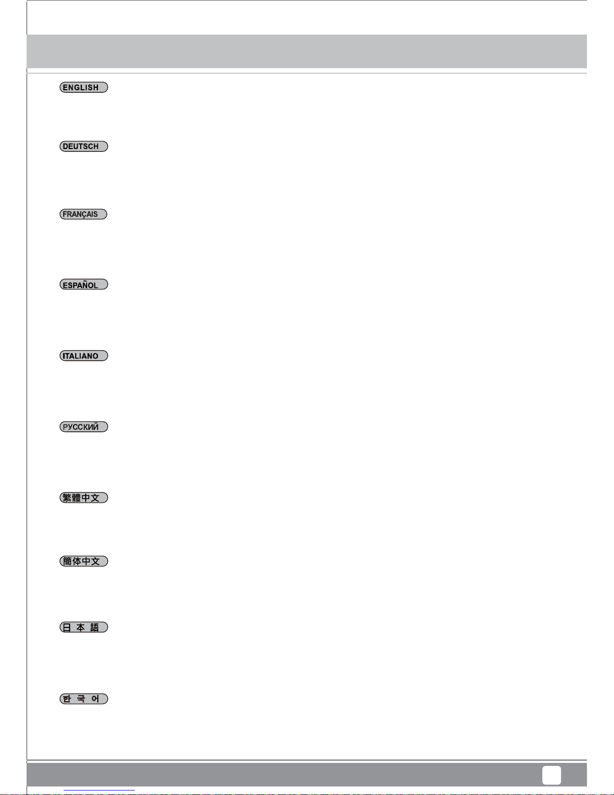
Q&A
50
Q: Can I remove and clean the front fan filter while the computer is turned on?
A: To reduce the chance of foreign objects touching and damaging the spinning fans while the system is on, we recommend only removing
and cleaning the filter when the system is off.
F: Kann ich den vorderen Lüfterfilter entfernen und reinigen, während der Computer eingeschaltet ist?
A: Damit bei eingeschaltetem System keine Gegenstände mit den rotierenden Lüftern in Kontakt kommen und diese beschädigen,
empfehlen wir, den Lüfter erst nach dem Ausschalten des Systems zu entfernen und zu reinigen.
Q: Puis-je enlever et nettoyer le filtre du ventilateur frontal lorsque l’ordinateur est allumé ?
R: Pour réduire le risque d’objet touchant et endommageant les ventilateurs en marche lorsque le système est allumé, nous vous
recommandons de n’enlever et de ne nettoyer les filtres que lorsque le système est éteint.
P: ¿Puedo retirar y limpiar el filtro del panel frontal mientras el ordenador está encendido?
R: Para reducir la posibilidad de que un objeto extraño toque y dañe las aspas en movimiento mientras el sistema está encendido, le
recomendamos que retire y limpie el filtro cuando el sistema esté apagado.
Q: Puis-je enlever et nettoyer le filtre du ventilateur frontal lorsque l’ordinateur est allumé ?
R: Pour réduire le risque d’objet touchant et endommageant les ventilateurs en marche lorsque le système est allumé, nous vous
recommandons de n’enlever et de ne nettoyer les filtres que lorsque le système est éteint.
В: Можно ли снимать и очищать фильтр переднего вентилятора во время работы компьютера?
О: Для снижения вероятности касания и повреждения инородными предметами вращающихся вентиляторов рекомендуется
снимать и очищать фильтр только после выключения системы.
Q: 可以在開機狀態下清理前面濾網嗎?
A: 在開機狀態下移除濾網,有可能會讓異物碰到正在運轉的扇葉。所以我們建議您先關機再清理濾網。
Q: 可以在开机状态下清理前面滤网吗?
A: 在开机状态下移除滤网,有可能会让异物碰到正在运转的扇叶。所以我们建议您先关机再清理滤网。
Q: コンピュータがオンの状態で、フロントファンフィルタを取り外して清掃してもよいですか?
A: システムがオンの間、異物が回転しているファンに触れて破損する可能性を小さくするため、システムがオフであるときにだけフィル
タを取り外して清掃することをお勧めします。
Q: 컴퓨터가 켜진 상태에서 프론트 팬 필터를 분리하여 청소해도 됩니까?
A: 시스템이 켜 있는동안 이물질이 회전 팬에 닿아 팬을 손상시킬 확률을 줄이기 위해 필터를 분리하여 청소할 때는 시스템을 끌 것을
권장합니다.
Mammoth Series MM01
Page 54

Q&A
51
Q: When I turn on the computer, why doesn’t the front 180mm spin?
A:
If your fan is connected to the motherboard, we suggest you to turn off temperature control function in the BIOS. If you want to use
temperature control function on your motherboard, we recommend you to set the MM01’s physical fan speed switch to high for a lower starting
voltage and a wider range of control. If the fans still do not spin, please contact reseller or SilverStone to arrange for replacement.
F: Warum dreht der vordere 180 mm-Lüfter nicht, wenn ich den Computer einschalte?
A: Falls Ihr Lüfter mit dem Motherboard verbunden ist, sollten Sie die Temperatursteuerungsfunktion im BIOS abschalten. Falls Sie die
Temperatursteuerungsfunktion an Ihrem Motherboard nutzen möchten, empfehlen wir, den physikalischen Lüftergeschwindigkeitsschalter
des MM01 auf hohe Geschwindigkeit einzustellen; dadurch werden eine geringere Startspannung und ein breiterer Steuerungsbereich
ermöglicht. Falls die Lüfter dennoch nicht drehen, wenden Sie sich zum Ersatz bitte an Ihren Händler oder SilverStone.
Mammoth Series MM01
Q: Quand j'allume l'ordinateur, pourquoi est-ce que le ventilateur frontal 180 mm ne tourne pas ?
R: Si votre ordinateur est connecté à la carte mère, nous vous suggérons de désactiver la fonction de contrôle de température du BIOS. Si
vous souhaitez utiliser la fonction de contrôle de la température de la carte mère, nous vous recommandons de régler le commutateur de
vitesse du ventilateur physique du MM01 sur Haut pour une tension au démarrage moins élevée et pour une gamme de contrôle plus
importante. Si le ventilateur ne tourne toujours pas, veuillez contacter le revendeur ou Silverstone pour convenir d'un remplacement.
.
P: Cuando enciendo el ordenador, ¿por qué no gira el ventilador frontal de 180mm?
R: Si su ventilador está conectado a la placa base, le sugerimos que apague la función de control de temperatura de la BIOS. Si desea usar
la función de control de temperatura de su placa base, le recomendamos que fije el interruptor de velocidad del ventilador físico del MM01 en
alto para un voltaje de inicio menor y un rango de control más amplio. Si los ventiladores todavía no giran, por favor contacte con su
distribuidor ó con SilverStone para conseguir un reemplazo.
D. Quando si accende il computer, perché la ventola anteriore da 180 mm non funziona?
R. Se la ventola è collegata alla scheda madre, si consiglia di disattivare la funzione di controllo della temperatura nel BIOS. Se si vuole usare
la funzione di controllo della temperatura sulla scheda madre, si raccomanda di impostare l’interruttore fisico di MM01 sull’alta velocità per una
tensione d’avvio più bassa ed una gamma di controllo più ampia. Se la ventola continua a non funzionare, contattare il rivenditore o
SilverStone per organizzare per la sostituzione.
В:
Почему при включении компьютера не вращается фронтальный 180-мм вентилятор?
О: Если вентилятор подключен к системной плате, мы предлагаем отключить функцию температурного контроля в BIOS. Если вы
хотите использовать функцию температурного контроля с системной платой, мы рекомендуем установить переключателем скорости
вентилятора в корпусе MM01 высокую скорость вращения для снижения напряжения запуска и расширения диапазона
контроля.
Если и в этом случае вентилятор не вращается, обратитесь к продавцу или в компанию SilverStone для его замены.
Q: 开机了但前置180mm风扇不会运转?
A: 如果您是把风扇插头插在主板上。建议您可以先将主板BIOS的风扇温控功能关掉。如果您想利用主板的温控功能,建议您应该把风扇的
转速切到高转,以得到更低的启动电压与更大的控制范围。如果无论如何风扇都不会运转,请尽速联络购买处,处理换货事宜。
Q: 私がコンピュータをオンにする、なぜ、正面180mmは回りませんか?
A: あなたのファンがマザーボードに接続しているならばA.と、我々はBIOSで温度調節機能をオフにするためにあなたに示唆します。あな
たがあなたのマザーボードの上で温度調節機能を使用したいならば、我々は低い立上げ電圧と支配のより広い範囲のためにMM01の身体的
なファン速度スイッチを高さに設定するとあなたに勧めます。扇風機がまだ回転しないならば、置き換えを手配するために、再販業者ま
た はシルバーストーンと交信してください。
Q. 컴퓨터를 켰을 때 프론트 180mm 팬이 회전하지 않는데,이유가 무엇입니까?
A. 팬을 메인보드에 연결했다면, BIOS에서 온도 제어 기능을 끌 것을 제안합니다. 메인보드에서 온도 제어 기능을 사용하고 싶을 경우, 더
낮은 전 압에서 시작하고 더 광범위하게 제어할 수 있도록 MM01의 실제 팬 속도 스위치를 고속으로 설정할 것을 권장합니다. 팬이 여전히
회전하지 않으면, 대리점 또는 SilverStone에 연락하여 교체하도록 하십시오.
Q: 開機了但前置180mm風扇不會運轉?
A: 如果您是把風扇插頭插在主機板上。建議您可以先將主機板BIOS的風扇溫控功能關掉。如果您想利用主機板的溫控功能,建議您應該把
風扇的轉速切到高轉,以得到更低的啟動電壓與更大的控制範圍。如果無論如何風扇都不會運轉,請儘速聯絡購買處,處理換貨事宜。
Page 55

Q&A
52
Q: I want to install customized liquid cooling system, do you have any recommendation?
A: Customized liquid cooling systems do not have a definite installation procedure. Typical chassis will not have provision for this. DIY users
must make provisions themselves. If you want to install a 3 x 120mm radiator, we recommend Magicool Dual 180 Radiator instead. Although
both types of radiators have the same length, the dual 180mm radiator has approximately 50% larger surface area for much higher
performance potential.
F: Ich möchte ein angepasstes Flüssigkühlsystem installieren; gibt es diesbezüglich irgendwelche Empfehlungen?
A: Angepasste Flüssigkühlsysteme haben kein eindeutiges Installationsverfahren. Typische Gehäuse bieten keine entsprechenden
Vorrichtungen. Bastler müssen derartige Vorrichtungen selbst vornehmen. Wir empfehlen Ihnen anstelle der Installation eines dreifachen 120
mm Kühlers die Verwendung eines zweifachen 180 mm Kühlers, beispielsweise “Magicool Dual 180”. Obwohl beide Kühlertypen etwa die
gleiche Länge haben, verfügt der zweifache 180mm Kühler über eine um etwa 50% größere Oberfläche und bietet so eine viel höhere
Kühlleistung.
Q: Je souhaite installer un système de refroidissement liquide personnalisé, avez-vous des recommandations?
R: Les systèmes de refroidissement liquide personnalisés n'ont pas de procédure d'installation définie. Un boîtier typique n'a pas de
dispositions pour cela. Les utilisateurs bricoleurs doivent prendre des dispositions eux-mêmes. Wir empfehlen Ihnen anstelle der Installation
eines dreifachen 120 mm Kühlers die Verwendung eines zweifachen 180 mm Kühlers, beispielsweise“Magicool Dual 180”. Obwohl beide
Kühlertypen etwa die gleiche Länge haben, verfügt der zweifache 180mm Kühler über eine um etwa 50% größere Oberfläche und bietet so
eine viel höhere Kühlleistung.
F: Ich möchte ein angepasstes Flüssigkühlsystem installieren; gibt es diesbezüglich irgendwelche Empfehlungen?
A: Angepasste Flüssigkühlsysteme haben kein eindeutiges Installationsverfahren. Typische Gehäuse bieten keine entsprechenden
Vorrichtungen. Bastler müssen derartige Vorrichtungen selbst vornehmen. Wir empfehlen Ihnen anstelle der Installation eines dreifachen 120
mm Kühlers die Verwendung eines zweifachen 180 mm Kühlers, beispielsweise “Magicool Dual 180”. Obwohl beide Kühlertypen etwa die
gleiche Länge haben, verfügt der zweifache 180mm Kühler über eine um etwa 50% größere Oberfläche und bietet so eine viel höhere
Kühlleistung.
D. Voglio installare il sistema personalizzato di raffreddamento a liquido, ci sono delle raccomandazioni?
A: I sistemi personalizzati di raffreddamento a liquido non hanno una procedura definita di installazione. I telai tipici non hanno istruzioni per
questo caso. Gli utenti fai da te devono trovare da sé le istruzioni. Se si sta pensando di installare una radiatore con ventole da 120 mm, si
raccomanda vivamente di installare invece un radiatore con due ventole da 180 mm, come “Magicool Dual 180”. Sebbene entrambi i tipi di
radiatore abbiano la stessa lunghezza, il radiatore con due ventole da 180 mm ha una superficie più grande di circa il 50 % per un potenziare
di prestazioni di gran lunga maggiore.
Q: 我需要安裝DIY水冷,有沒有什麼建議?
A: DIY水冷配件並沒有相關的定義來規範鎖固方式。一般機殼不會提供任何鎖固孔位,大多是玩家自己想辦法安裝。如果您考慮在前方安裝一
個3x120風扇規格的水冷排,我們建議您可以考慮Magicool Dual 180 Radiator。雖然長度一樣,但是從面積算上來2X180水冷排比3X120多了足
足有50%,可以提供更大的冷卻效能。
Q: 我需要安装DIY水冷,有没有什么建议?
A: 水冷配件并没有相关的定义来规范锁固方式。一般机壳不会提供任何锁固孔位,大多是玩家自己想办法安装。如果您考虑在前方安装一
个3x120风扇规格的水冷排,我们建议您可以考虑Magicool Dual 180 Radiator。虽然长度一样,但是从面积算上来2X180水冷排比3X120多了足
足有50%,可以提供更大的冷却效能。
В:
Я хочу установить заказную систему жидкостного охлаждения, могу я получит какие-либо рекомендации?
О: Заказные системы жидкостного охлаждения не имеют определенной процедуры установки. Типовые корпуса не
предусматривают такой возможности. Пользователи-умельцы (DIY-пользователи - "сделай сам") должны сделать это
самостоятельно. Если вы намерены установить тройной 120-мм радиатор, мы настоятельно рекомендуем вместо него
установить
двойной 180-мм радиатор типа "Magicool Dual 180". Хотя оба типа радиаторов имеют одинаковую длину, зона поверхности двойного
180-мм радиатора приблизительно на 50% больше, что обеспечивает улучшенные рабочие характеристики.
Mammoth Series MM01
Page 56

Q&A
53
Q:私がインストールしたいQ.は液体の冷却装置をカスタマイズしました、あなたには推薦がありますか?
A: カスタマイズされた液体冷却装置には、確かなインストール手順がありません。典型的シャシーは、これに対する準備をしません。D
IYユーザーは、準備自体をしなければなりません。3 x 120mmラジエターの設置をお望みの場合、その代わりMagicool Dual 180ラジエ
ターの装着をお勧めいたします。両タイプのラジエター共、同じ長さですが、デュアル180mmラジエターは表面積が約50%広く、より高
い性能を備えています。
Q. 사용자 지정 수냉 시스템을 설치하려고 합니다. 권장할 만한 사항이 있습니까?
A. 사용자 지정 수냉 시스템에는 한 가지로 정해진 설치 절차가 없습니다. 일반적인 섀시는 이에 대한 제공품이 없습니다. DIY 사용자가
필요한 부품을 직접 만들어야 합니다. 트리플 120mm 라디에이터 설치를 고려하고 있는 경우 트리플 대신 “Magicool Dual 180”과 같이 듀얼
180mm 라디에이터를 적극 권장합니다. 두 가지 유형의 라디에이터 모두 길이가 동일하지만 듀얼 180mm 라디에이터의 경우 면적이 약
50% 정도 넓어 성능이 훨씬높을 가능성이 있습니다.
Q: Why can’t the fans spin up to their top speed of 2000rpm in the MM01?
A: Usually high resistance introduced by HEPA filter (compared to ordinary computer filters) can reduce the top speed of AP182 by 200rpm.
This same effect will apply to any other fan installed in the MM01.
F: Warum erreichen die Lüfter im MM01 nicht ihre Spitzengeschwindigkeit von 2000 U/min?
A: Der durch den HEPA-Filter verursachte hohe Widerstand (im Vergleich zu herkömmlichen Computerfiltern) kann die Spitzengeschwindigkeit des AP182 um 200 U/min reduzieren. Dies gilt auch für andere im MM01 installierte Lüfter.
.
Q: Pourquoi les ventilateurs ne peuvent-ils pas tourner à leur vitesse maximale de 2000 rpm dans le MM01 ?
R: En général, la forte résistance induite par le filtre HEPA (par rapport à des filtres d'ordinateurs ordinaires) peut réduire la vitesse maximale
du AP182 de 200 rpm. Le même effet s'applique sur n'importe quel autre ventilateur installé dans le MM01.
.
P: ¿Por qué no pueden girar los ventiladores a su velocidad máxima de 2000rpm en el MM01?
R: Por lo general la alta resistencia que presenta el filtro HEPA (comparada con los filtros para ordenador normales) puede reducir la
velocidad máxima del AP182 en 200rpm. Este mismo efecto se aplicará a cualquier otro ventilador instalado en el MM01.
D. Perché le ventole di MM01 non girano alla loro velocità massima di 2000 rpm?
A. Solitamente l’alta resistenza introdotta dal filtro HEPA (rispetto ai normali filtri) può ridurre la velocità massima di AP182 di 200 rpm. Questo
stesso effetto si applica a qualsiasi altra ventola installata su MM01.
.
B: Почему скорость вращения вентиляторов не достигает максимального значения 2000 об/мин. при использовании в корпусе
MM01?
O: Обычно более высокое по сравнению с другими компьютерными фильтрами сопротивление воздушному потоку, создаваемое
фильтром HEPA может стать причиной
снижения максимальной скорости вращения вентилятора AP182 до 200 об/мин. Такой же
эффект присущ любым другим вентиляторам, устанавливаемым в корпус MM01.
Q: 开机了但前置180mm风扇不会运转?
A: 如果您是把风扇插头插在主板上。建议您可以先将主板BIOS的风扇温控功能关掉。如果您想利用主板的温控功能,建议您应该把风扇的转
速切到高转,以得到更低的启动电压与更大的控制范围。如果无论如何风扇都不会运转,请尽速联络购买处,处理换货事宜。
Q: 開機了但前置180mm風扇不會運轉?
A:
如果您是把風扇插頭插在主機板上。建議您可以先將主機板BIOS的風扇溫控功能關掉。如果您想利用主機板的溫控功能,建議您應該把風
扇的轉速切到高轉,以得到更低的啟動電壓與更大的控制範圍。如果無論如何風扇都不會運轉,請儘速聯絡購買處,處理換貨事宜。
Mammoth Series MM01
Page 57
54
Q&A
Q.どうしてMM01では、ファン回転数が最高速度の2000rpmに達しないのですか?
A. 通常、HEPAフィルターによる高い抵抗は(通常のコンピュータフィルターに比較して)、AP182の最高速度を200rpmほど低下させます。
これと同様の効果がMM01に装着された他のファンにも適用されます。
Q. MM01에서 팬이 최대 속도인 2,000rpm으로 회전하지 못합니다.
A. 일반적으로 HEPA 필터에 의한 높은 저항(일반적인 컴퓨터 필터에 비해)이 AP182의 최대 속도를 200rpm 정도 떨어뜨릴 수 있습니다.
이와 동일한 결과가 MM01에 설치된 다른 팬에도 적용됩니다.
Mammoth Series MM01
Page 58

55
Mammoth Series MM01
Warranty Information
For China (support@silverstonetek.com.cn)
For Europe (support.eu@silverstonetek.de)
For all other regions (support@silverstonetek.com)
Page 59

56
Mammoth Series MM01
Page 60

G11222061
 Loading...