

Page 1

LC10 / LC10M
Page 2

Specification:
Product Overview
LC10
Disassemble Chart
6025 FAN * 2
9225 FAN
3.5 BAY * 3 (HIDDEN)
STANDARD ATX M/B
FRONT IO (USB * 4)
FRONT IO (1394 + AUDIO)
POWER SW
RESET SW
5.25 BAY * 1
TOP PANEL
3.5 BAY * 1 (HIDDEN)
PS2 POWER SUPPLY
Material: Aluminum front panel, 1.0mm SECC body
Color: Black & Silver
Motherboard: A TX, Micro ATX
Drive Bay: External - 5.25" x 1
Internal - 5.25" x 1 / 3.5" x 4
Cooling System: Front - 92mm intake, 2100rpm, 21dBA
Rear - 2 x 60mm exhaust, 3000rpm, 23dBA
Expansion Slot: 7
Front I/O Port: USB2.0 x 4, IEEE1394 x 1, audio x 1, MIC x 1
Power Supply: Optional standard PS2 (ATX)
Net Weight: 8 kg
Dimension: 430 mm (W) x 163 mm (H) x 429 mm (D)
VFD (LC10M)
Page 3

Product Overview
Specification:
LC10M
Material: Aluminum front panel, 1.0mm SECC body
Color: Black & Silver
Motherboard: ATX, Micro ATX
Drive Bay: External - 5.25" x 1
Internal - 5.25" x 1 / 3.5" x 4
Cooling System: Front - 92mm intake, 2100rpm, 21dBA
Rear - 2 x 60mm exhaust, 3000rpm, 23dBA
Expansion Slot: 7
Front I/O Port: USB2.0 x 4, IEEE1394 x 1, audio x 1, MIC x 1
Multimedia: VFD, IR, remote control, iMon media center software
Power Supply: Optional standard PS2 (ATX)
Net Weight: 8 kg
Dimension: 430 mm (W) x 163 mm (H) x 429 mm (D)
LC10M
Multimedia Kit
Model Matrix
MODEL
LC10
LC10B(Black)
LC10S(Silver)
LC10B - M
LC10S - M
LC10M
W / Multimedia
Remote control, CD
Page 4

1. Unscrew four case screws to remove case
cover
13. Slide right front panel off from the case as
shown
19. A second 3.5" drive bracket is located
beneath the 5.25" drive bays with room for
one more hard drive. It can be taken out
of the case easily with a screw removed
20. After installing hard drive into the bracket,
slide it back underneath the 5.25" drive
bays
21. Secure reinstalled bracket with screw 22. For extra EMI protection, route front panel
cables through the included wire ring
23. Use included 3pin to 4pin adapter to connect
a case fan if your motherboard does not
support enough 3pin fan headers
24. After installing all other system components,
place the case cover back onto the case and
secure with screws to complete installation
14. Insert optical drive into the case 15. Slide right front panel back onto the case
and secure it with screws removed in
previous steps
16. Affix aluminum cover with double-sided tape
onto your optical drive tray door. Adjust
position of your optical drive so the aluminum
cover sits flush with the front panel
17. Secure optical drive with M3 screws 18. After optical drive is secured, reinstall 3.5"
drive bracket back into the case
7. Prepare your hard drive for installation 8. Use #6-32 x 6 screws to install hard drive
into the 3.5" drive bracket
9. Optical Drive Installation 10. Cut the included double-sided tape to match
your optical drive tray door and affix it to the
included aluminum cover prior to installation
11. Remove screw on top of the right front panel 12. Remove two screws behind the right front
panel
2. Check for Included accessories (screw bag,
3pin to 4pin adapter, EMI wire ring, aluminum
optical drive cover, double-sided tape)
3. Power Supply Installation- Insert power
supply into the case, secure with four #6 32 x 6 screws
6. Hard Drive Installation- Remove 3.5" drive
bracket from the case
5. Place motherboard into the case and
secure with screws
4. Motherboard Installation- Insert included
motherboard standoffs into holes on the
bottom of the case that will lineup with
your motherboard
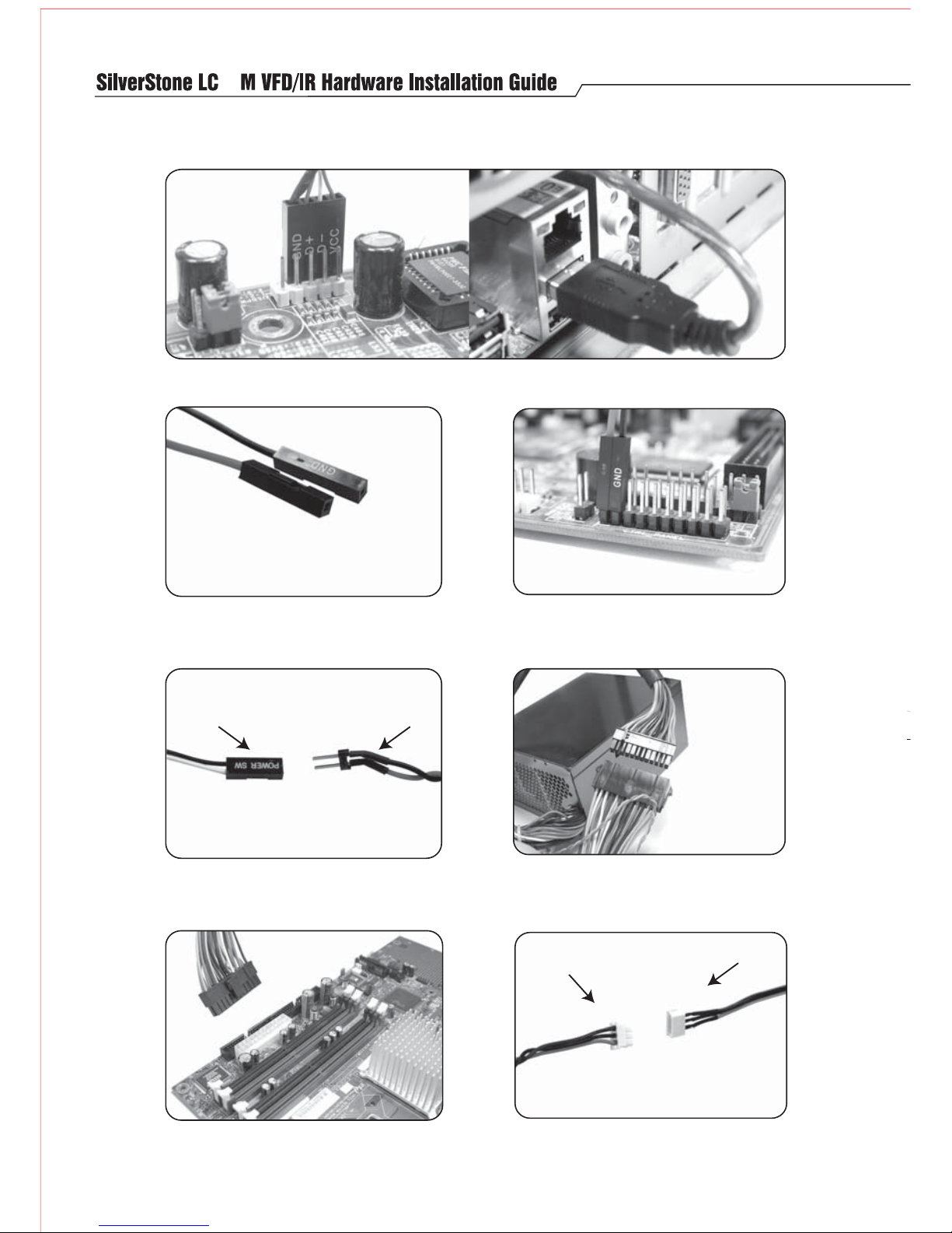
Page 5
10
From front panel From VFD/IR module
From ATX adapter
From VFD/IR module
Finally, connect the 3 pin power connector from
the VFD/IR module to the ATX adapter's 3pin cable
Connect the other end of the ATX adapter to your
motherboard. It is compatible with 24pin or 20pin
motherboards.
Connect the included ATX adapter to your power
supply's ATX connector.
Refer to your motherboard manual and connect
the two wire leads to "power switch" or "power
button" on the motherboard's front panel pin
headers
From the front panel VFD/IR module, locate two
female single wire leads colored in black and red.
The black wire should have the connector labeled,
"GND"
Insert the 4 pin USB connector from the VFD/IR module to your motherboard USB pin header. You can also
use the included USB adapter to connect to an external USB port header on the motherboard
Connect your power switch connector from the front
panel to the dual pin header from the VFD/IR module
Page 6

ation
Page 7

NO:11400207
December , 2005
 Loading...