

Page 1

Kublai Series
A remarkable and clever Micro-ATX tower chassis
KL06
Page 2

Page 3
The following manual and guides were carefully prepared by the SilverStone engineering team to
help you maximize the potential of your SilverStone product. Please keep this manual for future
reference when upgrading or performing maintenance on your system. A copy of this manual can also
be downloaded from our website at:
Warranty Information
Installation and system optimization guide:
Product Overview
Special Features
Specification
Disassemble Chart
Exterior Overview
Installation Chart
Connector Definition
Componet Size Limitations
Graphics Card Supporter
Optimal Thermal Performance Layout
Upgrade And Maintenance
Water pump installation on bottom panel
Protect Your Computer
Questions and Answers
P.1
P.1
P.1
P.2
P.3
P.4
P.22
P.25
P.32
P.34
P.38
P.43
P.44
P.45
Page 4
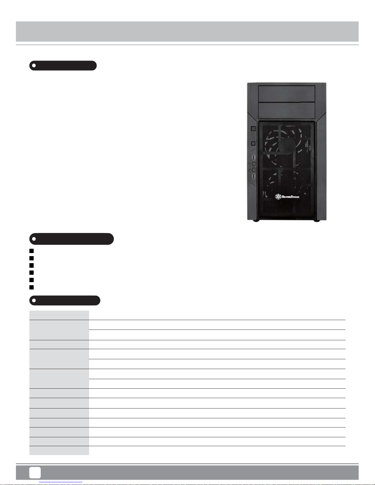
Product Overview
Specification
Material
Model
Motherboard
Drive Bay
Cooling System
Expansion Slot
Front I/O Port
Power Supply
Expansion Card
Limitation of CPU cooler
Limitation of PSU
Dimension
Plastic front panel with steel mesh, steel body
SST-KL06B (black)
SST-KL06B-W (black + window)
Micro ATX, Mini-DTX, Mini-ITX
Exposed
Internal
Front
Rear
4
USB 3.0 x 2, Audio x 1, MIC x 1
Optional PS2 (ATX)
Compatible up to 14.5” in length, width restriction – 6.99”
165mm
180mm*
211mm (W) x 375mm (H) x 405mm (D)
* Power supply and optical drive’s combined allowable total length is 404mm including connectors, which may take up additional 20mm. We suggest maximum length for PSU at 180mm (ST1500-GS).
5.25" x 2
3.5" x 1 , 2.5” x 8
120mm intake fan x 2, 1200rpm, 20dBA
120mm fan slot x 1
Kublai Series KL06
Introduction
1
Being the first Micro-ATX chassis in the Kublai series, a line of cases famed for
layout efficiency with classic styling, the KL06 fills the role perfectly. Equipped with
dual 120mm quiet fans for cooling multiple drives and high-end components, it retains
SilverStone’s signature positive pressure design for effective dust prevention.
With an internal body structure based on the benchmark Temjin TJ08-E and
Precision PS07, the KL06 was designed to meet current and future demands with
unique features. These include accommodation for 13.5 inch long graphics cards
and simultaneous front/rear all-in-one liquid cooler support without drive cage
removal. For more convenient access during assembly and for advanced enthusiasts,
the KL06 has removable drive cage, motherboard tray, and top panel plus provision
for custom liquid cooling pump. Maintenance is remarkably easy thanks to externally
accessible filters on the front panel and independent power supply vent. Finally for
storage expansion, the KL06 has a forward-thinking layout that focuses on 2.5” drives
with a total of eight bays that include tool-less cage and a special bracket from
RAVEN RV02 for showing off installed SSD on its side.
For those looking for an expertly designed Micro-ATX case built for the future and
designed to beautifully complement any computing environment, the SilverStone
Kublai KL06 is as clever of a choice as it gets.
Special Features
Up to eight 2.5” drives and one 3.5” drive capacity
Innovative drive cage design enables support for front and rear AIO liquid coolers
Modular design with removable drive cage, motherboard tray, and top panel
Includes two quiet 120mm fans
Convenient externally removable fan filters
Independent power supply intake vents
Page 5
Kublai Series KL06
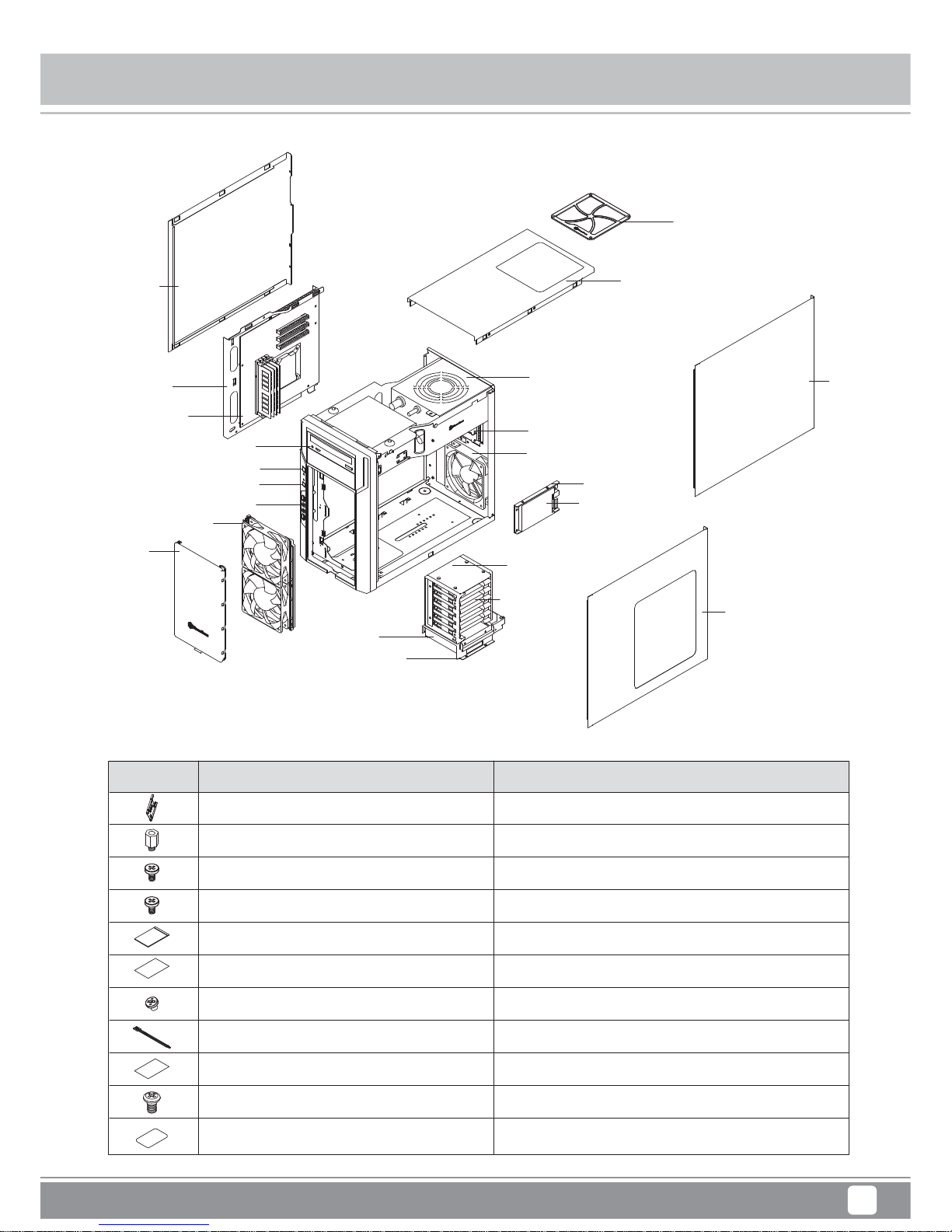
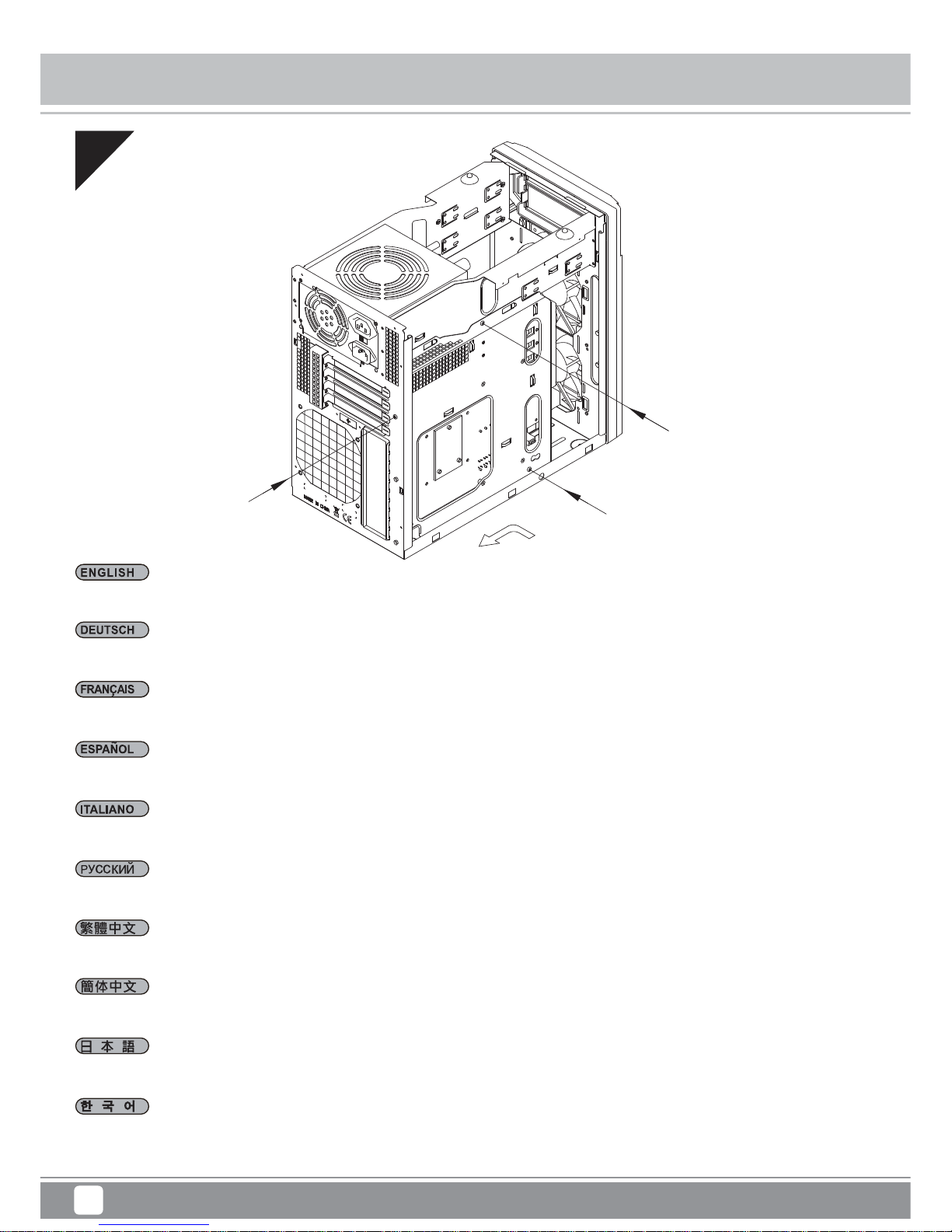
Disassemble Chart
2
PICTURE PURPOSEITEM
SCW - M3 X 6 (B)
ZIPPER BAG
SCW - M3 (A)
632 - 6.5 - STANDOFF
2 - 5 - HDD - BKT
MANUAL
SCW - 6 - 32
RUBBER GASKET EXTRA CARD SUPPORT
BUNCH WIRE TIES
SCW - 6 - 32 X 5
ZIPPER BAG
SECURE MOTHERBOARD
SECURE 2.5”HDD ON RIGHT BRACKET
SECURE WIRE
INSTALLATION GUIDE
SECURE MOTHERBOARD AND OPTICAL DRIVE
SECURE 2.5” HDD
SECURE HDD BRACKET
LEFT SIDE
PANEL
MOTHERBOARD
TRAY
MOTHERBOARD
(OPTION)
5.25” BAY X 2
POWER BUTTON
RESET BUTTON
FRONT I/O
12025 FAN X 2
FAN FILTER
3.5” HDD X 1
2.5” HDD X 6
2.5” HDD X 1
SSD BRACKET
EXPANSION SLOT X 4
PS2 PSU (OPTION)
TOP COVER
PSU FILTER
RIGHT
SIDE
PANEL
RIGHT SIDE PANEL
WINDOW
12025 FAN (OPTION)
2.5” HDD
DRIVE CAGE
2.5” HDD X 1
SECURE POWER SUPPLY
Page 6
Kublai Series KL06
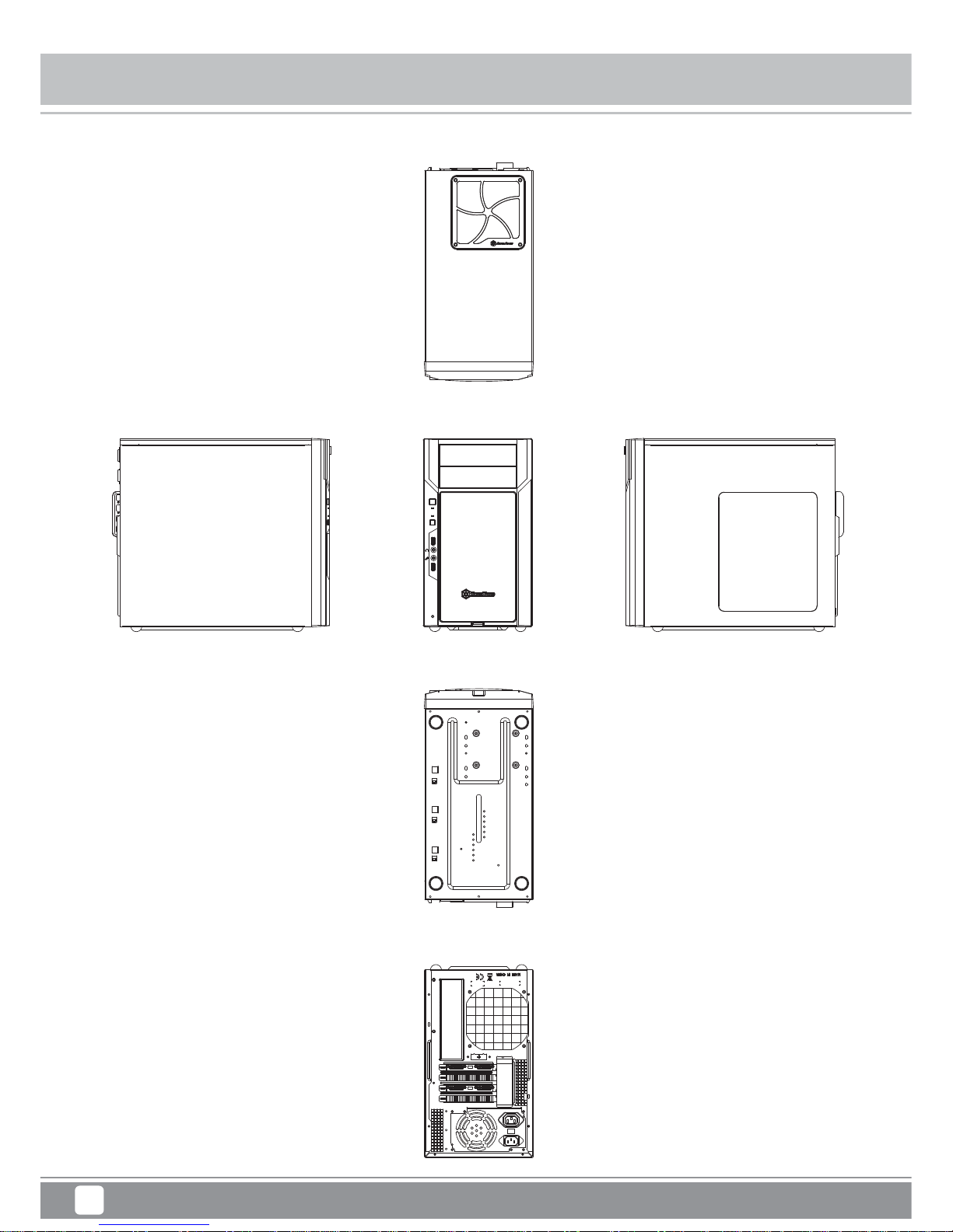
Exterior Overview
TOP
BOTTOM
FRONT
BACK
RIGHT SIDELEFT SIDE
3
Page 7
Kublai Series KL06
4
Installation Chart
have all components collected
check that all components do not have compatibility problems with each other or with the case
if possible, assemble the components outside the case first to make sure they are working
keep the motherboard manual ready for reference during installation
prepare a Philips screwdriver.
1
2
3
4
5
Before you begin, please make sure that you
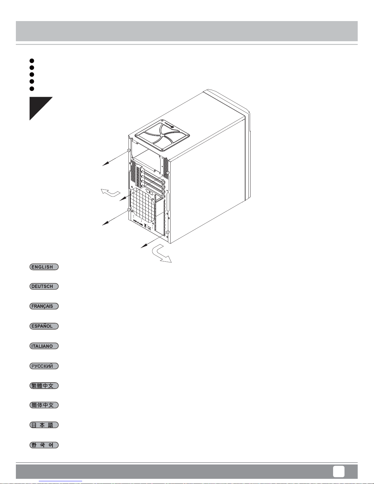
01
Lösen Sie die beiden Schrauben an den linken und rechten Seitenwänden, nehmen Sie die Seitenwände ab.
Desatornille dos tornillos de los paneles izquierdo y derecho para quitarlos.
Per rimuovere i pannelli laterali allentare, per entrambi, le due viti di serraggio.
Loosen two screws from both left and right side panels to remove them.
Отвинтите по два винта, крепящих левую и правую боковых панели, и снимите панели.
取下左右側板兩顆螺絲卸下側板。
取下左右侧板两颗螺丝卸下侧板。
왼쪽과 오른쪽 사이드 패널에서 두 개씩 나사를 풀어 사이드 패널을 제거합니다.
両方の左右パネルからネジ2本を緩めて、取り外します。
Desserrez les vis des deux panneaux latéraux pour les retirer.
Page 8
5
Installation Chart
02
Lösen Sie sechs Schrauben an der oberen Abdeckung, nehmen Sie die Abdeckung ab.
Desatornille seis tornillos del panel superior para quitarlo.
Per rimuovere il pannello superiore allentare le sei viti di serraggio.
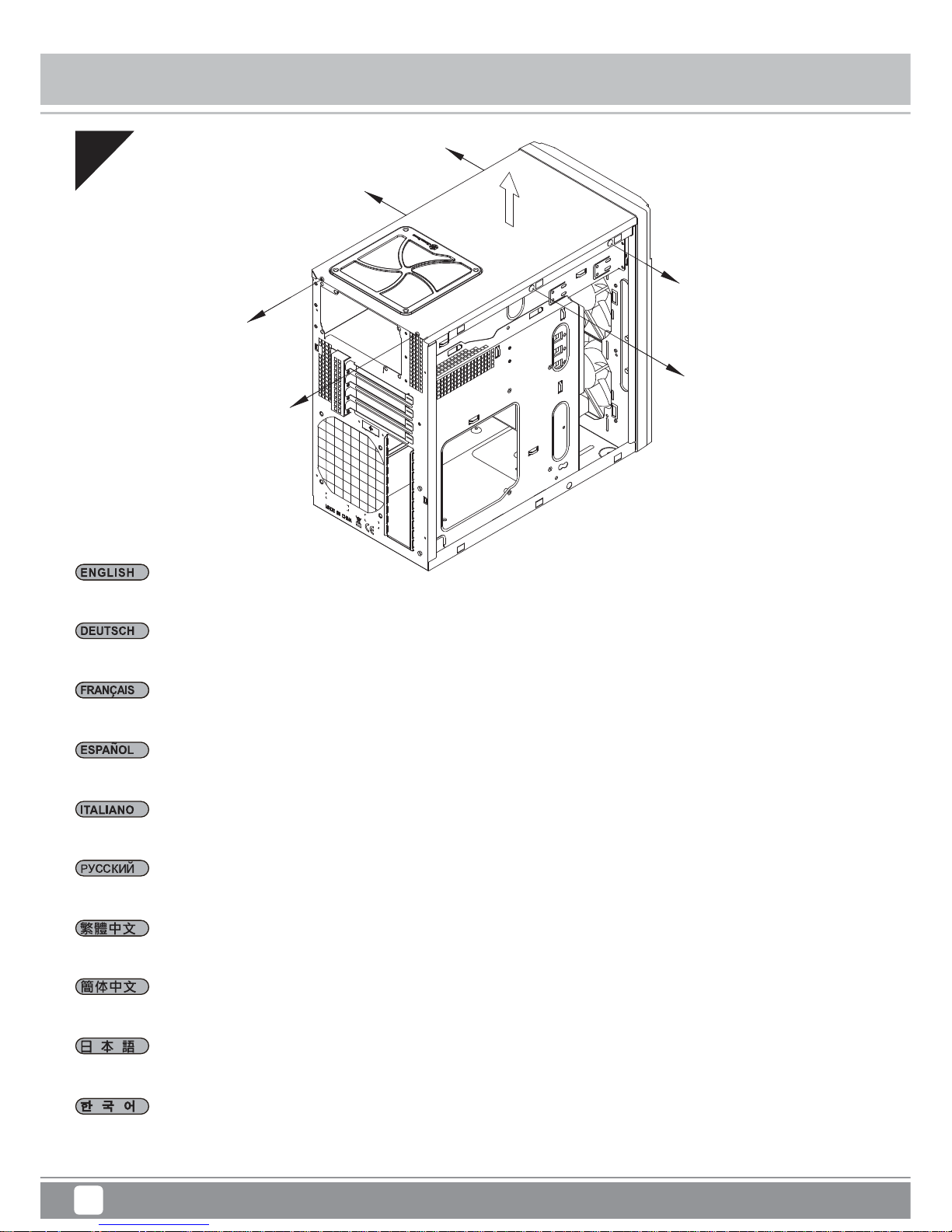
Loosen six screws from the top panel to remove it.
Отвинтите шесть винтов, крепящих верхнюю панель, и снимите ее.
取下上蓋6顆螺絲取出上蓋。
取下上盖6颗螺丝取出上盖。
상부패널의 6개 나사를 제거한 후 상부 패널을 제거합니다.
上部パネルからネジ6本を緩めて取り外します。
Desserrez les six vis du panneau supérieur pour le retirer.
Kublai Series KL06
Page 9

6
Installation Chart
03
Lösen Sie die drei Schrauben, welche die Motherboard-Halterung fixieren, nehmen Sie die Halterung ab.
Desatornille tres tornillos que sujetan la bandeja de la placa base para quitarla.
Per rimuovere il supporto scheda madre allentare le tre viti di serraggio.
Loosen three screws holding the motherboard tray to remove it.
Отвинтите три винта, крепящих кронштейн материнской платы, и снимите его.
取下主機板托盤3顆螺絲,將主機板托盤抽出。
取下主机板托盘3颗螺丝,将主机板托盘抽出。
3개의 나사를 풀어 메인보드 트레이를 제거합니다.
マザーボードトレイを固定しているネジ3本を緩めて、取り外します。
Desserrez les trois vis tenant le plateau de la carte mère pour le démonter.
Kublai Series KL06
Page 10
7
Installation Chart
04
Setzen Sie das Netzteil von oben ein; sofern das Netzteil über einen 120 mm-Lüfter (oder größer) verfügt, empfehlen wir, das Netzteil mit dem Lüfter
nach oben einzubauen.
Inserte la fuente de alimentación desde arriba, si la fuente de alimentación tiene un ventilador de 120mm ó más grande incluido, le recomendamos
que instale la fuente de alimentación con su ventilador hacia hasta.
Inserire l’alimentatore dalla parte superiore, se lo stesso possiede una ventola da 120mm o più grande, vi raccomandiamo di installarlo con la ventola
in cima.
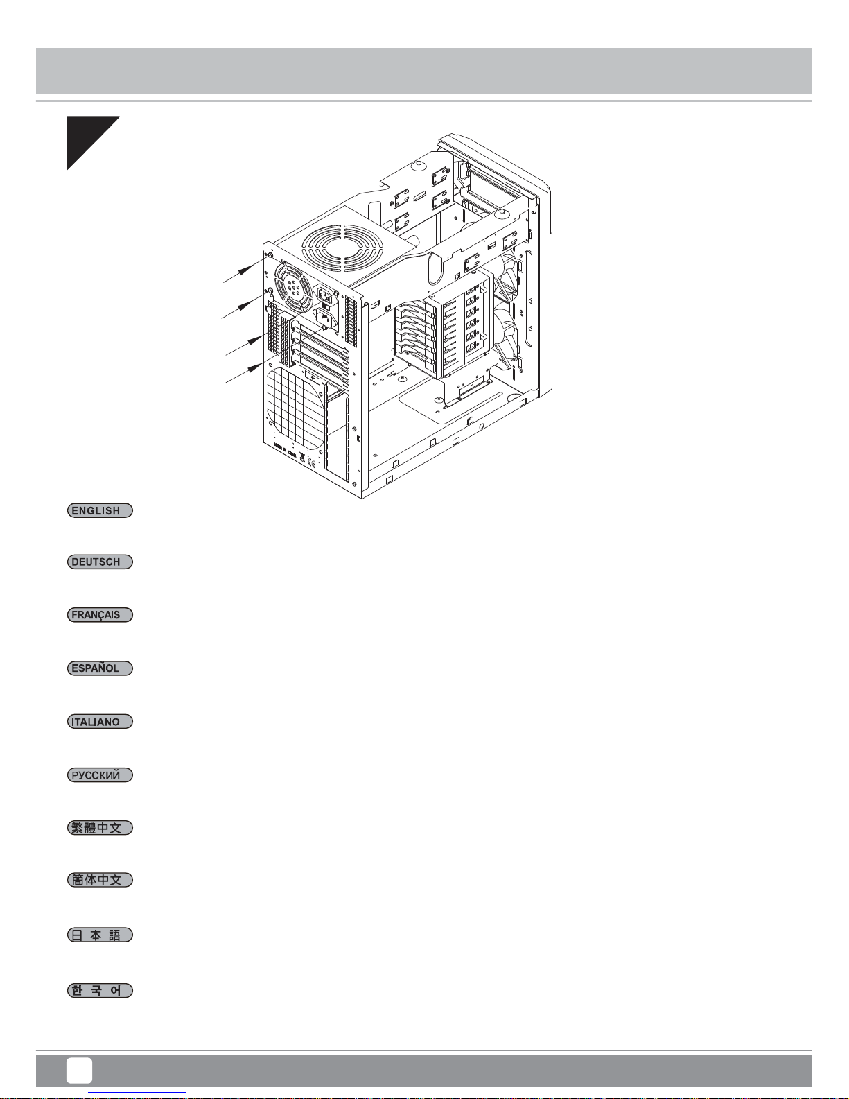
Insert the power supply from the top, if the power supply has a build-in 120mm fan or larger, we recommend installing the power supply with its fan
facing up.
Установите блок питания в верхней части корпуса. Если блок питания оснащен встроенным вентилятором размером 120 мм или больше,
рекомендуется устанавливать блок питания вентилятором вверх.
將電源供應器由上放入機殼內,如果有12公分或以上尺寸的風扇建議朝上放置
将电源供应器由上放入机壳内,如果有12公分或以上尺寸的风扇建议朝上放置
파워 서플라이를 위에서부터삽입합니다. 만약 파워서플라이에 120mm 이상의 팬이장착되어 잇는 경우 파워서플라이의 팬이 최대쪽을향하도록
설치합니다.
上部から電源を入れます。電源が内蔵で120mmまたはより大きなファンを備えている場合は、ファンが上向きになるよう電源を取り付けるようお
勧めします
Insérez l'alimentation par le dessus, si l'alimentation possède un ventilateur intégré de 120mm ou plus, nous vous recommandons de l'installer avec
le ventilateur orienté vers le haut.
Kublai Series KL06
Page 11

8
Installation Chart
05
Installieren Sie das 2,5 Zoll-Laufwerk im unteren Teil des Gehäuses; anschließend mit Schrauben fixieren.
Instale el disco de 2,5” en la parte inferior de la carcasa y fíjelo con tornillos.
Installare il drive da 2,5” nella parte bassa dello chassis ed assicurarlo alla struttura con le viti in dotazione.
Install 2.5” drive into the bottom of the chassis and secure with screws.
Установите 2,5-дюймовый жесткий диск в нижнюю часть корпуса и закрепите его винтами.
將2.5”硬碟裝入機殼底部,並鎖上螺絲。
将2.5”硬盘装入机箱底部,并锁上螺丝。
2.5”드라이브를 케이스 바닥에 장착한 후 나사로 고정합니다.
ケース底部に2.5インチドライブを装着し、ネジで固定します。
Installez le lecteur 2.5” dans le bas du boîtier et fixez-le avec des vis.
Kublai Series KL06
Page 12
9
Installation Chart
06
Installieren Sie das hintere I/O-Blech im Gehäuse.
Instale la placa trasera de E/S de la placa base en la carcasa.
Installare la placca I/O della scheda madre nella sede preposta.
Install motherboard rear I/O plate into the chassis.
Установите в корпус заднюю панель ввода-вывода материнской платы.
將I/O彈片裝上機殼。
将I/O弹片装上机箱。
메인보드 후방 I/O 판을 케이스에 장착합니다.
ケース内にマザーボード後部I/Oプレートをインストールします。
Installez la plaque arrière de la carte mère dans le boîtier.
Kublai Series KL06
Page 13

10
Installation Chart
07
Installieren Sie das Motherboard auf der Motherboard-Halterung. Sofern Sie bereits einen großen CPU-Kühler auf dem Motherboard installiert haben,
empfehlen wir, die 4-poligen ATX12V- oder 8-poligen EPS-Kabel vom Netzteil jetzt an das Motherboard anzuschließen; dies erleichtert die weitere
Installation.
Instale la placa base en la bandeja de la placa base. Si ya tiene instalado un disipador grande de CPU en la placa base, le recomendamos que
conecte los cables ATX12V 4 pines ó EPS 8 pines de su fuente de alimentación a la placa base ahora para que la instalación sea más fácil después.
Installare la scheda madre sul supporto. Se avete già montato un dissipatore per CPU di grandi dimensioni, vi consigliamo di collegare i connettori
dei cavi ATX12V 4pin o EPS 8pin dell’alimentatore subito, per renderne più semplice la connessione.
Install motherboard onto the motherboard tray. If you have already installed a large CPU cooler on the motherboard, we recommend connecting
ATX12V 4pin or EPS 8pin cables from your power supply to the motherboard now to make installation easier later on.
Установите материнскую плату на кронштейн материнской платы. Если на материнскую плату уже установлен процессорный кулер большого
размера, на данном этапе рекомендуется подсоединить к материнской плате 4-контактный разъем кабеля ATX 12 В или 8-контактный
разъем кабеля EPS от блока питания для упрощения дальнейшего процесса установки.
將主機板安裝於主機板托盤,如果您已經裝上大型CPU散熱器,我們建議您先在機殼外把ATX 4Pin / EPS 8pin插上電源線。如果電源線夠長或為模
組化電源線,安裝步驟將更為順利。
将主机板安装于主机板托盘,如果您已经装上大型CPU散热器,我们建议您先在机箱外把ATX 4Pin / EPS 8pin插上电源线。如果电源线够长或为模
块化电源线,安装步骤将更为顺利。
메인보드를 메인보드 트레이에 설치합니다. 메인보드에 커다란 CPU쿨러를 설치한 경우, ATX12V 4핀이나 EPS 8핀 케이블을 파워 서플라이에서
메인보드로 미리 연결하여, 나중의 설치를 편하게 합니다.
マザーボードトレイ上にマザーボードを取り付けます。マザーボードに大型CPUクーラーがインストール済みならば、あとのインストールが容易
に行えるよう、電源からATX12V 4ピンまたはEPS 8ピンケーブルをマザーボードにこの時点で接続しておくようにお勧めします。
Installez la carte mère sur son support. Si vous avez déjà installé un dissipateur de processeur de grande taille sur la carte mère, nous vous
recommandons de brancher tout de suite les câbles ATX12V 4pin ou EPS 8pin de votre alimentation à sur votre carte mère pour rendre l'installation
plus facile plus tard.
Kublai Series KL06
Page 14
11
Installation Chart
08
Setzen Sie die Motherboard-Halterung nebst Motherboard wieder in das Gehäuse ein. Sofern Sie das 4-polige ATX12V- oder das 8-polige EPS-Kabel
bereits angeschlossen haben, achten Sie darauf, dass das Kabel durch die Öffnung zwischen Netzteil und Motherboard verläuft.
Reinstale la bandeja de la placa base montada de nuevo en el chasis. Si tiene instalado el cable ATX12V 4 pines ó EPS 8 pines, asegúrese por favor
de haberlos pasado a través de la abertura entre la fuente de alimentación y el compartimento de la placa base.
Reinstallare la scheda madre ed il supporto nel cabinet. Se avete collegato anche i connettori dei cavi ATX12V 4pin o EPS 8pin, assicuratevi di averli
fatti passare nell’apertura posta tra l’alimentatore ed il compartimento della scheda madre.
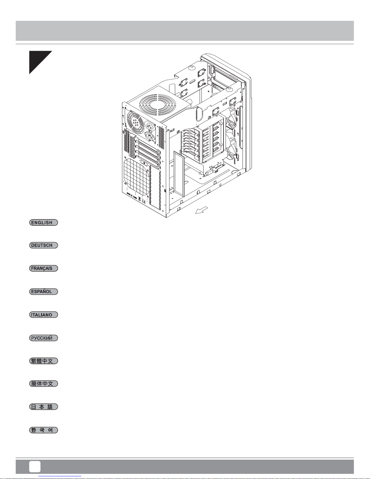
Reinstall the assembled motherboard tray back into the chassis. If you have either the ATX12V 4pin or EPS 8pin cables connected, please make
sure to have it pass through the opening between power supply and the motherboard compartment.
Установите кронштейн с материнской платой в сборе в корпус. Если был подключен 4-контактный разъем кабеля ATX 12 В или 8-контактный
разъем кабеля EPS, кабель необходимо проложить через отверстие между блоком питания и отсеком для материнской платы.
將MB底板裝回機殼,如果已經接上ATX 4pin / EPS 8Pin線材,請注意線材通過下方的缺口。
将MB底板装回机箱,如果已经接上ATX 4pin / EPS 8Pin线材,请注意线材通过下方的缺口。
조립된 메인보드 트레이를 케이스에 재 설치합니다. 만약 ATX12V 4핀이나 EPS 8핀 케이블이 연결되어 있다면, 파워 서플라이와 메인보드 쪽
빈공간을 케이블이 지나가도록 합니다.
組み上げたマザーボードトレイをケースに戻します。ATX12V 4ピンまたはEPS 8ピンケーブルのいずれかが接続されているならば、ケーブルが電
源とマザーボードコンパートメントの間の開口部を通っていることを確かめてください
Remettez la carte mère assemblé à son support dans le boîtier. Si vous avez soit le câble ATX12V 4pin soit le câble EPS 8pin déjà branché, veuillez
bien vérifier de l'avoir passé par l'ouverture entre l'alimentation et le compartiment de la carte mère.
Kublai Series KL06
Page 15

12
Installation Chart
09
Wir empfehlen, jetzt mit dem Verlegen der Kabel zu beginnen und die 24-poligen ATX-, Front-I/O- und sämtliche weiteren Kabel von Geräten an der
Frontblende anzuschließen.
Le recomendamos que empiece a gestionar el enrutado de cables ahora y conecte cables como el ATX 24 pines, los conectores frontales E/S y
cualquier otro conector de los dispositivos del panel frontal.
Vi raccomandiamo di iniziare subito la sistemazione delle connessioni e collegare quindi i connettori relativi ai cavi ATX 24pin, alle connessioni I/O
frontali e qualsiasi altro collegamento delle periferiche poste frontalmente.
We recommend that you start cable manage now and connect cables such as the ATX 24pin, front I/O connectors, and any other connectors from
front panel devices.
На этом этапе рекомендуется начать прокладку кабелей и подсоединить кабели, например кабель ATX с 24-контактным разъемом, разъемы
ввода-вывода передней панели и любые другие разъемы от устройств на передней панели.
我們建議您可以在此時開始理線,請先插上ATX 24Pin接線、Front panel controller與Front I/O。
我们建议您可以在此时开始理线,请先插上ATX 24Pin接线、Front panel controller与Front I/O。
이 단계에서부터 ATX 24핀, 전면 I/O 커넥터, 그리고 전면 패널에서의 다른 커넥터 등 케이블 정리를 하시기를 권장합니다.
この時点でケーブル取り回しを考えながら、ATX 24ピン、フロントI/Oコネクタ、その他フロントパネルデバイスからのコネクタ類のケーブルを
接続するようお勧めします。
Nous vous recommandons de commencer à gérer l'organisation des câbles maintenant comment l'ATX 24pin, les connecteurs des ports E/S de
façade, et tout autre connecteur des appareils du panneau frontal.
Kublai Series KL06
Page 16
13
Installation Chart
10
Verlegen Sie sämtliche Netzteilkabel durch die Öffnung links vom Netzteil. Nicht verwendete Kabel können Sie an der freien Stelle rechts vom Netzteil
unterbringen. Wenn Sie ein Netzteil mit modularen Kabel verwenden, entfernen Sie nicht gebrauchte Kabel bitte.
Enrute todos los cables de la fuente de alimentación por la abertura a la izquierda de la fuente de alimentación. Los cables que no se usen se pueden
almacenar en el espacio extra en el lado derecho de la fuente de alimentación. Si tiene una fuente de alimentación con cables modulares, quite por
favor los cables no usados.
Convogliare tutti i cavi dell’alimentatore verso l’apertura alla sinistra dell’alimentatore stesso. I cavi inutilizzati possono essere riposti nello spazio
extra alla destra dell’alimentatore. Se possedete una PSU modulare, rimuovete i cavi non utilizzati.
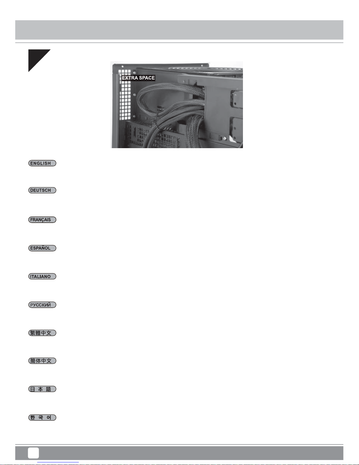
Route all power supply cables to the opening on the left of the power supply.
Unused cables can be stored in the extra space to the right of the power supply. If you have a power supply with modular cables, please
removed unused cables.
Проложите все кабели питания через отверстие слева от блока питания. Неиспользуемые кабели можно хранить в дополнительном отсеке
справа от блока питания. Если блок питания оснащен модульными кабелями, отсоедините неиспользуемые кабели.
請將所有電源線穿過電源左邊的開孔,將不需用到的線材綁在電源左側的空間;若使用模組化電源,請移除用不到的線材。
请将所有电源线穿过电源左边的开孔,将不需用到的线材绑在电源左侧的空间;若使用模块化电源,请移除用不到的线材。
모든 파워서플라이 케이블을 파워서플라이의 왼쪽 빈 공간에 정리해줍니다. 사용되지 않는 케이블은 파워 서플라이의 오른쪽 빈공간에 정리할 수
있습니다. 모듈라 케이블을 가진 파워서플라이의 사용되지 않는 케이블을 제거해 주십시요.
全ての電源ケーブルを電源の左上の開口部に通します。未使用のケーブルは電源右の専用スペースに収納できます。モジュラーケーブル装備の
電源の場合は、未使用のケーブルを取り外してください。
Faîtes passer tous les câbles de l'alimentation par l'ouverture situé à sa gauche. Les câbles non utilisés peuvent être logés dans l'espace
supplémentaire disponible à sa droite. Si vous avez une alimentation à câblage modulaire, veuillez-les détacher.
Kublai Series KL06
Page 17

14
Installation Chart
11
Dem Sie die Abdeckung der 5,25-Zoll-Laufwerkschächte ab, installieren Sie die gewünschten 5,25-Zoll-Geräte.
Quite las cubiertas para bahía de dispositivos de 5,25” para instalar los dispositivos de 5,25” necesarios.
Per installare le necessarie periferiche da 5,25”, rimuovere il cover del bay da 5,25”
Remove the 5.25” drive bay covers to install required 5.25” devices.
Снимите крыши отсеков для 5,25-дюймовых устройств и установите необходимые 5,25-дюймовые устройства.
移除5.25”檔板,安裝5.25”裝置。
移除5.25”档板,安装5.25”装置。
5.25”드라이브 베이 커버를 제거한 후 필요한 5.25” 장치를 설치합니다.
5.25インチドライブベイカバーを外して、必要な5.25インチデバイスを装着します。
Retirez les caches des baies 5.25” pour installer vos appareils.
Kublai Series KL06
Page 18

15
Installation Chart
12
Wenn sich die direkte Installation eines 3,5-Zoll-Laufwerks im unteren Käfig als schwierig erweist, kann der Käfig durch Lösen der Schrauben an
der Gehäuseunterseite entfernt werden.
Si instalar un dispositivo de 3,5” en la carcasa inferior resulta difícil, la carcasa se puede retirar quitando los tornillos de la parte inferior del chasis.
Se installare l’unità da 3,5" direttamente nella gabbia inferiore risulta difficoltoso, la gabbia può essere rimossa svitando le viti sulla parte inferiore
del telaio.
If installing 3.5” drive directly into the bottom cage is difficult, the cage can be removed by unscrewing screws on the bottom of the chassis.
Если вам трудно установить 3,5-дюймовый диск непосредственно в нижний отсек, отсек можно извлечь, отвернув винты в нижней части
корпуса.
安裝底部3.5吋硬碟時,如果難以安裝,可先移除底部螺絲,取出硬碟架,再將3.5吋硬碟鎖固於硬碟架上。
安装底部3.5吋硬盘时,如果难以安装,可先移除底部螺丝,取出硬盘架,再将3.5吋硬盘锁固于硬盘架上。
3.5” 드라이브를 하단 케이지에 직접 설치하기가 쉽지 않을 경우, 섀시 하단에 있는 나사를 풀어 케이지를 제거할 수 있습니다.
3.5”ドライブを底部ケージに装着するのが難しい場合、ケース底部のネジを外すことでケージが取り外せます。
Si l'installation du disque de 3,5" directement dans la cage du fond est difficile, cette cage peut être enlevée en retirant les vis de la partie inférieure
du châssis.
Kublai Series KL06
Page 19

16
Installation Chart
13
Bauen Sie 2,5-Zoll-Laufwerke in den Hauptlaufwerkkäfig ein.
Instalar dispositivos de 2,5” en la carcasa principal para dispositivos.
Installare le unità da 2,5” nella gabbia principale.
Install 2.5” drives into the main drive cage.
Установите 2,5-дюймовые диски в главный отсек для дисков.
將2.5吋硬碟安裝至主硬碟架。
将2.5吋硬盘安装至主硬盘架。
2.5” 드라이브를 기본 드라이브 케이지에 설치합니다.
2.5”ドライブを主ドライブケージに装着します。
Installez les disques de 2,5" dans la cage de disques principale.
Kublai Series KL06
Page 20

17
Installation Chart
14
Ein zusätzliches 2,5-Zoll-Laufwerk kann an der mitgelieferten (siehe Zubehörschachtel) 2,5-Zoll-Laufwerkhalterung installiert werden.
Se puede instalar un dispositivo adicional de 2,5” en la carcasa incluida para dispositivos de 2,5” de la caja de accesorios.
È possibile installare unità da 2,5” aggiuntive utilizzando il supporto disco rigido da 2,5” fornito insieme agli accessori.
Additional 2.5” drive can be installed onto the included 2.5” drive bracket from the accessories box.
Дополнительный 2,5-дюймовый диск можно установить на кронштейн для 2,5-дюймовых дисков из комплекта дополнительных
принадлежностей.
將2.5吋硬碟安裝至零件包的硬碟支架。
将2.5吋硬盘安装至零件包的硬盘支架。
액세서리 박스에 제공된 2.5” 드라이브 브래킷에 추가 2.5” 드라이브를 설치할 수 있습니다.
追加の2.5”ドライブは、付属のアクセサリーボックスに含まれる2.5”ドライブブラケットに装着できます。
Un disque de 2,5" supplémentaire peut être installé sur le support de disque 2,5" inclus dans la boîte d'accessoires.
Kublai Series KL06
Page 21

18
Installation Chart
15
Sichern Sie die 2,5-Zoll-Laufwerkhalterung am Gehäuse und verbinden Sie alle Kabel für 5,25-, 3,5- bzw. 2,5-Zoll-Laufwerke wie erforderlich mit
den verlegten Kabeln.
Asegure el bracket para dispositivos de 2,5” a la carcasa y conecte todos los cables para dispositivos de 5,25”, 3,5” y 2,5” según sea necesario con
los cables enrutados.
Fissare il supporto disco rigido da 2,5” sul case e collegare tutti i cavi per le unità da 5,25”, 3,5” e 2,5”, come necessario, disponendo i cavi in modo
appropriato.
Secure 2.5” drive bracket to the case and connect all cables for 5.25”, 3.5”, 2.5”drives as needed with cables routed.
Прикрепите кронштейн для 2,5-дюймового диска к корпусу и подключите все кабели для 5,25-дюймовых, 3,5-дюймовых, 2,5-дюймовых
дисков.
將2.5寸硬碟架鎖固於機身,並連接所有磁碟線材及整線排列(包含5.25吋、3.5吋、2.5吋)。
将2.5寸硬盘架锁固于机身,并连接所有磁盘线材及整线排列(包含5.25吋、3.5吋、2.5吋)。
2.5” 드라이브 브래킷을 케이스에 고정하고, 필요한 경우 케이블 경로를 정리하면서 5.25”, 3.5”, 2.5” 드라이브용 케이블을 모두 연결합니다.
2.5”ドライブブラケットをケースに固定し、必要に応じて5.25”, 3.5”, 2.5”ドライブのケーブル全てを配線して接続します。
Fixez le support de lecteur 2,5" sur le boîtier et raccordez tous les lecteurs 5,25", 3,5" ou 2,5" selon vos besoins, avec les câbles routés.
Kublai Series KL06
Page 22

19
Installation Chart
16
Entfernen Sie Steckplatzabdeckungen, installieren Sie die gewünschten Erweiterungskarten. Bei nicht verwendeten Steckplätzen sollten die
Abdeckungen angebracht bleiben.
Quite las cubiertas de los zócalos de expansión para instalar las tarjetas de expansión necesarias. Los zócalos no usados deberían tener cubiertas
instaladas.
Rimuovere i cover degli slot di espansione per installare le schede. Gli slot inusati dovrebbero conservare i cover.
Remove expansion slot covers to install required expansion cards. Unused slots should have covers installed.
Снимите крышки слотов расширения для установки необходимых плат расширения. На неиспользуемые слоты следует установить крышки.
移除擴充槽檔片並安裝擴充卡,未使用的擴充槽請將檔片裝回並以內附螺絲鎖固。
移除扩充槽档片并安装扩充卡,未使用的扩充槽请将档片装回并以内附螺丝锁固。
확장슬롯 커버를 제거한 후, 필요한 확장카드를 설치 합니다. 사용되지 않은 슬롯의 슬롯 커버는 다시 설치 합니다.
拡張スロットカバーを取り外して、必要な拡張カードを装着します。未使用のスロットにはカバーを取り付けたままにします。
Retirez les équerres pour installer vos cartes d'extension. Les emplacements inutilisés doivent garder leur équerre.
Kublai Series KL06
Page 23

20
Installation Chart
17
Bauen Sie die obere Abdeckung wieder ein.
Reinstale el panel superior
Reinstallare il pannello superiore.
Reinstall the top panel.
Установите на место верхнюю панель.
裝回上蓋。
装回上盖。
상부 패널을 재 설치 합니다.
上部パネルを元に戻します
Réinstallez le panneau supérieur.
Kublai Series KL06
Page 24

21
Installation Chart
18
Installieren Sie zum Abschluss der Installation die linke und rechte Seitenwand wieder.
Reinstale los paneles laterales izquierdo y derecho para completar la instalación.
Reinstallare entrambi i pannelli laterali per completare l’installazione.
Reinstall both left and right side panel to complete installation.
Для завершения установки установите на место левую и правую боковые панели.
裝回左右側板,完成組裝。
装回左右侧板,完成组装。
왼쪽과 오른쪽 사이드 패널을 모두 재 설치해 설치를 마칩니다.
両方の左右パネルを元に戻すと、インストールは完了です。
Réinstallez les deux panneaux latéraux pour terminer le montage.
Kublai Series KL06
Page 25

22
Connector Definition
Kublai Series KL06
A.Power switch and reset switch installation guide:
Please refer to the motherboard manuals for the motherboard’s “Front Panel Connector” or “System Panel Connector” pin definitio
Power switch and reset switch have no polarity, so they can be connected in any orientation.
Bitte suchen Sie in der Motherboard-Dokumentation nach der Pinbelegung der Anschlüsse des Frontbedienfeldes („Front Panel Conne
oder „ System Panel Connectors“). Ein-/Austaste und Rücksetztaste benötigen keine bestimmte Polarität, können daher beliebig (o
und - zu achten) angeschlossen werden.
Veuillez-vous référer au manuel de votre carte mère pour la description des broches "des connecteurs du panneau frontal" et des
"des connecteurs du panneau système". Les interrupteurs d'allumage et de réinitialisation ne possède pas de polarité, donc ils peuvent être
branché dans les deux sens.
Por favor, consulte en los manuales de la placa base la configuración de pines del “Conector de panel frontal” ó “Conector de panel de sistema”
de su placa base. Los interruptores de encendido y reseteo no tienen polaridad, luego se pueden conectar con cualquier orientac
Fare riferimento al manuale della scheda madre nella sezione “Connettori del pannello frontale” o “Connettori del pannello di sistema”. Power
switch e reset switch non hanno polarità, posso essere pertanto connessi con qualsiasi orientamento.
Описание контактов разъемов приведены в разделах “Разъемы передней панели” или “Разъемы системной панели” руководства
пользователя материнской платы. Выключатель питания и кнопка перезагрузки не имеют полярности, поэтому их можно подключать
в любой ориентации.
請參考主機板說明書的Front Panel Connectors安裝Pin Define,將Connector插上;Power Switch 與Reset Switch並無正負極性之分,
反插正插都不影響功能性。
请参考主机板说明书的Front Panel Connectors安装Pin Define,将Connector插上;Power Switch 与Reset Switch
并无正负极性之分,
反插正插都不影响功能性。
메인보드 매뉴얼의 전면패널 커넥터 혹은 시스템패널 커넥터 핀을 참조하기 바랍니다. 파워 스위치와 리셋 스위치는 극 성이 없어 어떤
방향으로 설치해도 무방합니다.
マザーボードの「フロントパネルコネクタ」または「システムパネルコネクタ」のピン配列についてはマザーボードマニュアルを参照してください。
電源スイッチとリセットスイッチに極性はないので、いずれの方向でも接続できま。
(1) Front Panel Connectors
Page 26

23
Connector Definition
Kublai Series KL06
Please refer to the motherboard manuals for the motherboard’s “Front Panel Connector ” or “System Panel Connector” pin definition.; the white/black
wires are negative while other colors are positive wires. The Power LED wires are separate pins for compatibility with different motherboard pin
definition so please make sure they are connected in the right polarity by referring to your motherboard manual.
Bitte suchen Sie in der Motherboard-Dokumentation nach der Pinbelegung der Anschlüsse des Frontbedienfeldes („Front Panel Connectors“ oder „
System Panel Connectors“). Die weißen/ schwarz Adern sind negativ (-), die farbigen Adern positiv (+).Die Kabel für die Betriebsanzeige-LED sind
zur Kompatibilität mit unterschiedlichsten Motherboards einzeln, nicht als kompletter Stecker ausgeführt. Achten Sie hier bitte auf die richtige
Polarität, lesen Sie in der Dokumentation Ihres Motherboards nach.
Veuillez-vous référer au manuel de votre carte mère pour la description des broches "des connecteurs du panneau frontal" et des broches "des connecteurs du panneau
système". Les câbles colorés en blanc/noir sont négatifs alors que ceux d'une autre couleur sont positifs. Les câbles de la LED Power sont séparés afin d'être compatible
avec différentes cartes mères, donc vérifiez bien qu'ils sont branchés avec la bonne polarité en vous référant au manuel de votre carte mère
Por favor, consulte en los manuales de la placa base la configuración de pines del “Conector de panel frontal” ó “Conector de panel de sistema” de
su placa base. Los cables de color blanco/negro son negativos mientras que los de color son positivos. Los cables LED de potencia tienen pines
separados para compatibilidad con diferentes definiciones de pines de la placa base luego por favor, asegúrese de que están conectados en la
polaridad correcta consultando el manual de su placa base.
Fare riferimento al manuale della scheda madre nella sezione “Connettori del pannello frontale” o “Connettori del pannello di sistema”. I cavi di
colore bianco/nero sono il polo negativo, mentre quelli di colore diverso il positivo.
Описание контактов разъемов приведены в разделах “Разъемы передней панели” или “Разъемы системной панели” руководства
пользователя материнской платы. Белые/черный провода - отрицательной полярности, цветные провода - положительной полярности.
Провода светодиодного индикатора питания имеют отдельные контакты для совместимости с различными типами контактов материнских
плат, поэтому обратитесь к руководству пользователя материнской платы и убедитесь, что полярность соблюдена.
請參考主機板說明書的Front Panel Connectors安裝Pin Define,將Connector插上;白/黑色線的部分為負極,彩色線的部分是正極。
Power LED為了適應各主機板的不同, 特別設計為散Pin樣式,請安心使用。
请参考主机板说明书的Front Panel Connectors安装Pin Define,将Connector插上;白/黑色线的部份为负极,彩色线的部份为正极。
Power LED为了适应主机板的不同, 特别设计为散Pin样式,请安心使用。
메인보드 매뉴얼의 전면패널 커넥터 혹은 시스템패널 커넥터 핀을 참조하기 바랍니다. 하얀/검은선의 경우 음극이며, 다른 색의 경우
양극입니다. 파워 LED 선은 분리되어 다양한 메인보드에서 동작할 수 있도록 되어 있습니다. 그러므로 메인보드 매뉴얼을 참조하여 올바를
극성을 주의해 선택하시기 바랍니다.
マザーボードの「フロントパネルコネクタ」または「システムパネルコネクタ」ピン配列についてはマザーボードマニュアルを参照してください。
白/黑色のリード線はマイナスで、色の着いたリード線がプラスです。電源LEDリード線は種々のマザーボードピン定義と互換性を持たせるため分離されたピ
ンとなっているので、ご使用のマザーボードマニュアルを参照して、適切な極性に接続されるようお確かめください。
B:LED indicators installation guide
(1) Front Panel Connectors
Page 27

24
Connector Definition
Kublai Series KL06
Below are the front I/O connectors pin definition, please also check your motherboard manual to cross reference with motherboard’s
front I/O pin headers. SilverStone’s I/O connectors are in block type to simplify installation.
Nachstehend finden Sie die Pinbelegung der vorderen E/A-Anschlüsse; bitte gleichen Sie zudem das Handbuch Ihres Motherboards mit
den vorderen E/A-Pinzuweisungen ab. SilverStones E/A-Anschlüsse befinden sich zur Vereinfachung der Installation in Blockart.
Au dessous de la description des broches des ports d'E/S, veuillez aussi vérifier sur le manuel de votre carte mère de manière croisée
que les broches sont correctement placées. Les connecteurs d'E/S de SilverStone sont en bloc pour en simplifier leur installation.
A continuación tiene la definición de pines de los conectores frontales de E/S, también debe consultar el manual de su placa base para c
omprobar la referencia de los pines para E/S frontales. Los conectores de E/S de SilverStone son de bloque para simplificar la instalación.
Di seguito lo schema delle connessioni I/O frontali, confrontare lo schema con quanto riportato sul manuale della scheda madre per
effettuare una controllo incrociato. I connettori I/O Silverstone, per semplificare l’installazione, sono del tipo “a blocco”.
Ниже приведено описание контактов передних разъемов ввода/вывода. Обратитесь также к руководству пользователя материнской
платы за описанием передних разъемов ввода/вывода типа "пин-хедер". Разъемы ввода/вывода "SilverStone" - блочного типа, что
облегчает сборку.
下表為Front I/O Connectors的Pin Define,請參閱主機板說明書的各Front I/O Connectors Pin Define一一核對。
Front I/O Connectors完全採用集合Pin方式以簡化安裝。
下表为Front I/O Connectors的Pin Define,请参阅主机板说明书的各Front I/O Connectors Pin Define一一核对。
Front I/O Connectors完全采用集合Pin方式以简化安装。
아래는 전면 I/O 커넥터의 핀 설정이며, 메인보드 매뉴얼을 참조해 메인보드의 전면 I/O 핀 헤더와 맞추어 설치합니다.
Silverstone의 I/O 커낵터는 블록 타이브로 구성되어 설치를 간편화 했습니다.
以下はフロントI/Oコネクタピン配列ですが、お持ちのマザーボードのフロントI/Oピンヘッダは、マザーボードマニュアルをご参照ください。
シルバーストーンのI/Oコネクタは、インストールの容易なブロックタイプになっています。
(2) Front I/O connector guide
USB 3.0 CONNECTOR HD CONNECTOR
Pin
PORT2L
SENSE_SEND
PORT2R
PORT1R
PORT1L
SENSE2_RETURN
PIN
SENSE1_RETURN
PRESENCE
AUD GND
Pin 19
Pin 11Pin 10
Pin 1
Vbus
IntA_P2_SSRX-
IntA_P2_SSTXIntA_P2_SSTX+
IntA_P2_DIntA_P2_D+
IntA_P2_SSRX+
GND
GND
Vbus
IntA_P1_SSRX-
IntA_P1_SSTX-
IntA_P1_SSTX+
IntA_P1_D-
IntA_P1_D+
IntA_P1_SSRX+
GND
GND
ID
Page 28

25
Component Size Limitations
Kublai Series KL06
(1) CPU cooler height limitation
The KL06 can accommodate all standard size components and even some that are out of spec, please refer to the following guidelines for component
selection and future upgrade considerations:
The height limit is 165mm and there is 18mm of clearance around the motherboard’s top edge.
The clearance toward the front of the case is variable depending on how much you fill the hard drive cage. There is 252mm of clearance from the
end of an installed hard drive to the motherboard minus a approximately 11mm for a 90 degree angled SATA connector (less room with 180 degree
connectors).
Das Höhenlimit beträgt 165 mm, an der Oberkante des Motherboards verbleiben 18 mm Freiraum. Der Freiraum zur Front des Gehäuses hin ist
variabel und hängt davon ab, wie die Laufwerkhalterung gefüllt wurde. Zwischen dem Ende einer installierten Festplatte und dem Motherboard
verbleiben 252 mm Freiraum abzüglich etwa 11 mm bei um 90 ° abgewinkelten SATA-Verbindern (bei 180 °-Verbindern bleibt weniger Platz frei).
La hauteur maximale est de 165mm et il y a une espace de 18mm autour du bord
supérieur de la carte mère. L'espace vers l'avant du boîtier varie selon la façon dont vous avez remplie le casier à disques durs. Il y a un espace
de 252mm entre le bord des disques durs installés et de la carte mère moins approximativement 11mm pour un connecteur SATA à 90 degrés
(encore moins d'espace avec un connecteur standard à 180 degrés).
La altura límite es de 165mm y existe un espacio de 18mm alrededor del extremo superior de la placa base. El espacio hacia el frontal de la carcasa
es variable dependiendo de lo mucho que llene la carcasa para discos duros. Existe un espacio de 252mm hacia el final de un disco duro instalado
en la placa base menos unos 11mm para un conector SATA en ángulo de 90 grados (menos espacio con conectores de 180 grados).
Il limite in altezza è di 165mm e ci sono 18mm di tolleranza intorno al bordo superiore della scheda madre. La tolleranza verso la parte frontale del
case dipende da quanti hard drive sono installati nel supporto. Ci sono 252mm di tolleranza tra l’estremità di un hard drive installato e la scheda
madre meno approssimativamente 11mm di un connettore SATA a 90° (meno spazio con connettori a 180°).
Максимальная высота кулера – 165 мм, и зазор вокруг верхнего края материнской платы должен составлять 18 мм. Зазор до
передней панели корпуса зависит от количества устройств в кронштейне для жестких дисков. Зазор должен составлять 252 мм от края
установленного жесткого диска до материнской платы минус приблизительно 11 мм для углового SATA-разъема (90 градусов) (с плоскими
разъемами (180 градусов) остается меньше места).
높이는165mm로 제한되며, 메인보드의 상부 가장자리와18mm의 간격이 있습니다. 케이스 전면과의 여유 공간은 얼마나 많은 드라이브를
설치하는가에 따라 다릅니다. 설치된 드라이브로 부터 메인보드까지 약252mm의 여유 공간이 있고,90도 SATA 커넥터를 사용할 경우 11mm가
줄어 듭니다. (일반180도 커넥터를 사용할 경우 이 공간은 더 줄어듭니다. )
Cooler限高是165mm,Cooler外緣允許超出主機板上邊界18mm。Cooler前邊界則需要視您需不需要安裝大量硬碟,硬碟尾部距離主機板後端有252mm,再
扣除90度線材所需要最短的空間11mm。
Cooler限高是165mm,Cooler外缘允许超出主板上边界18mm。Cooler前边界则需要视您需不需要安装大量硬盘,硬盘尾部距离主板后端有252mm,再扣除
90度线材所需要最短的空间11mm。
高さ制限は165mmであり、マザーボード上の周囲に18mmの伱間があります。ハードドライブケージに何台装着するかによって、ケース正面へ
の距離は変わります。インストールされたハードドライブの終わりからマザーボードまでから約11mm引くと、90度角のSATAコネクタ(180度コ
ネクタより少ない空間)のために252mmの伱間があります。
252mm
18mm
165mm
Page 29

26
Component Size Limitations
Kublai Series KL06
(2) Power supply and optical drive limitation
The Total length for power supply and optical drive:
Power supply and the optical drive space in the KL06 share the same plane so the total limit is 404mm including possible room for cables. We
recommend maximum size for power supply of up to 180mm such as the SilverStone’s ST1500-GS.
Gesamtlänge Netzteil und optisches Laufwerk:
Netzteil und optisches Laufwerk liegen beim KL06 in derselben Ebene; daher stehen maximal 404 mm einschließlich Raum für Kabel zur Verfügung.
Wir empfehlen Netzteile mit einer maximalen Größe bis 180
mm, z. B. das SilverStone ST1500-GS.
Longueur totale de l'alimentation et du lecteur :
Les logements pour l''alimentation et le lecteur optique partage le meme plan dans le KL06 est dispose d'un longueur limite de 404mm en incluant
l'espace pour les câbles. Nous vous recommandons une taille maximale pour l'alimentation de 180mm comme la SilverStone ST1500-GS.
Longitud total de la fuente de alimentación y dispositivo óptico:
El espacio de la fuente de alimentación y el dispositivo óptico en la KL06 comparten el mismo plano, luego el límite total es 404mm, incluyendo
espacio posible para cables. Le recomendamos un tamaño máximo de la fuente de alimentación de hasta 180mm, como la Silverstone ST1500-GS.
Lunghezza totale per alimentatore e drive ottico:
Lo spazio per l’alimentatore ed il drive ottico, nel case KL06, condividono lo stesso piano che ha una lunghezza totale di 404mm incluso lo spazio
per eventuali cavi. Vi raccomandiamo di scegliere alimentatori con lunghezza massima di 180mm come il SilverStone ST1500-GS.
Общая длина блока питания и приводов оптических дисков:
Блок питания и привод оптических дисков в корпусе KL06 расположены на одной панели, поэтому их общая длина не может превышать
404 мм, включая возможное пространство для кабелей. Рекомендуется использовать блок питания длиной не более 180 мм, например
модель SilverStone ST1500-GS.
파워 서플라이와 광드라이브의 총 길이 제한.
파워서플라이와 광드라이브 는 KL06에 있어서 동일한 공간을 사용하며, 케이블에 필요한 여유공간을 감안하여 총 사용가능 길이는 404mm입니다.
파워 서플라이의 경우SilverStone의 ST1500-GS와 같이 180mm 까지의 파워 서플라이 사용을 권장합니다.
PSU與光碟機的總合限制:
KL06的電源與光碟機相對,允許的總長度是404mm,另外扣除線材所需要的空間,我們建議最大安裝到180mm的電源供應器,例如銀欣ST1500-GS。
PSU与光驱的总合限制:
KL06的电源与光驱相对,允许的总长度是404mm,另外扣除线材所需要的空间,我们建议最大安装到180mm的电源供应器,例如银欣ST1500-GS。
電源および光学ドライブの全長:
電源と光学ドライブはKL06内で同じ面を共有した配置なので、ケーブルのための余裕を含んだ合計長さ限度は404mmです。電源に対しては、
SilverStoneのST1500-GS.などの最大サイズ180mmの電源が推薦されます。
404mm
185mm
242mm
Page 30

27
Component Size Limitations
Kublai Series KL06
The absolute maximum length for optical drive is 242mm. Once the optical drive length surpasses 207mm, it will start to encroach the cable routing
hole to the right of the power supply compartment.
Die absolute Maximallänge von optischen Laufwerken liegt bei 242 mm. Überschreitet die Länge des optischen Laufwerks 207 mm, wird dadurch
die Kabelführungsöffnung rechts neben dem Netzteil beeinträchtigt.
La taille maximale des lecteurs optique est de 242mm. Si le lecteur optique dépasse les 207mm, il commencera à occuper l'espace destine au trou
du compartiment de l'alimentation utilisé pour faire passer les câbles.
La longitud máxima absoluta para un dispositivo óptico es de 242mm. Una vez la longitud del dispositivo óptico sobrepasa los 207mm, empezará
a ocupar el espacio del agujero de enrutado a la derecha del compartimento de la fuente de alimentación.
La lunghezza massima assoluta per il drive ottico è di 242mm. Una volta che il drive ottico supera i 207mm, inizierà ad interferire con il foro per il
cable routing disposto alla destra della zona dell’alimentatore.
Максимально допустимая длина привода оптических дисков составляет 242 мм. Если длина привода оптических дисков превышает 207 мм,
он будет блокировать отверстие для прокладки кабелей в правой части отсека блока питания.
광드라이브를 위한 최대 공간은 242mm 입니다. 광드라이브가 207mm를 상회할 경우 파워 서플라이 오른쪽의 케이블 정리 공간과 간섭이
일어나기 시작합니다.
光碟機的長度限制為242mm。而光碟機只要長度超過207mm將會擋住電源左邊的背位理線孔。
光驱的长度限制为242mm。而光驱只要长度超过207mm将会挡住电源左边的背位理线孔。
光学ドライブのための最大絶対長は242mmです。光学ドライブ長が207mmを超えると、それは電源コンパートメント右へのケーブル通しホー
ルにカブり始めます。
Page 31

28
Component Size Limitations
Kublai Series KL06
Power supply cable length recommendation
Netzteilkabel – Längenempfehlungen
Recommandations de longueurs des câble de l'alimentation:
Recomendaciones de la longitud del cable de la fuente de alimentación:
Рекомендации по длине кабелей блока питания
Рекомендации по длине кабелей блока питания
파워 서플라이 케이블 길이 및 권장사항
電源線材建議長度:
电源线材建议长度:
電源ケーブル推奨長さ:
Page 32

29
Component Size Limitations
Kublai Series KL06
(3) Liquid cooler install limitations
240mm (120mm x 2)
radiator mounting holes
140mm (140mm x 1)
radiator mounting holes
Secure with 3 screws
Secure with 3 screws
Secure with 4 screwsMove main drive cage toward
the rear by 30mm
Move main drive cage toward
the rear by 45mm
Move main drive cage toward
the rear by 60mm
Secure with 4 screws
Page 33

30
Component Size Limitations
Kublai Series KL06
Liquid cooler install limitations
KL06 can support 240mm (120mm x 2) or 140mm radiators and its main drive cage has three mounting points for 30/45/60mm of additional room to
support various radiator thickness.
*Note* Moving main drive cage toward the rear requires sacrifice of bottom 2.5”drive space. 240mm radiator installation my also take up room in
the second 5.25” drive bay.
Beschränkungen bei der Installation eines Flüssigkühlers
KL06 kann 240-mm- (120 mm x 2) oder 140-mm-Kühlkörper aufnehmen und sein Hauptlaufwerkgehäuse hat drei Montagepunkte für 30/45/60 mm
zusätzlichen Platz zur Unterstützung unterschiedlich dicker Kühlkörper.
*Hinweis* Wenn Sie die Hauptlaufwerkhalterung nach hinten bewegen möchten, müssen Sie auf Platz für das untere 2,5-Zoll-Laufwerk verzichten.
Die Installation eines 240-mm-Kühlkörpers kann zudem Platz im zweiten 5,25-Zoll-Laufwerkschacht erfordern.
Limitations relatives à l'installation d'un refroidissement liquide
Le KL06 peut prendre en charge des radiateurs de 240 mm (120 mm x 2) ou 140 mm et sa cage de lecteurs principale comprend trois points de
fixation pour 30/45/60 mm d'espace supplémentaire afin de prendre en charge différentes épaisseurs de radiateurs.
*Remarque* Le fait de déplacer la cage de lecteurs principale vers l'arrière nécessite de sacrifier l'emplacement disque 2,5" du fond. L'installation
du radiateur 240 mm peut également prendre de la place dans la seconde baie de lecteur 5,25".
Limitaciones para la instalación de refrigeración líquida
El KL06 acepta radiadores de 240mm (120mm x 2) o 140mm y su carcasa principal para dispositivos tiene tres puntos de montaje para 30/45/60mm
de espacio adicional para aceptar diversos grosores de radiadores.
*Nota* Mover la carcasa principal de dispositivos hacia la parte trasera precisa de sacrificar espacio inferior para un dispositivo de 2,5”. La instalación
de un radiador de 240mm también podría ocupar espacio en la segunda bahía para dispositivos de 5,25”.
Limitazioni d’installazione dei sistemi di raffreddamento a liquido
KL06 supporta radiatori da 240 mm (120 mm x 2) o da 140 mm e la sua gabbia principale è dotata di tre punti d’installazione dotati di 30/45/60 mm
di spazio aggiuntivo per accomodare radiatori di vari spessori.
*Nota* Spostando la gabbia principale verso la parte posteriore sarà sacrificato lo spazio inferiore per l’unità da 2,5”. Anche l’installazione del
radiatore da 240 mm può occupare parte dello spazio del secondo alloggio unità da 5,25”.
Ограничения по установке кулера с жидкостным охлаждением
KL06 поддерживает установку 240-мм (120-мм x 2) или 140-мм радиаторов, а главный отсек для дисков имеет три точки крепления с
дополнительным пространством 30/45/60 мм для установки радиаторов различной толщины.
*Примечание* Для перемещения главного отсека для дисков к задней части потребуется пожертвовать пространством для установки
2,5-диска в нижней части. Установка 240-мм радиатора может также занять пространство второго 5,25-дюймового отсека.
수냉식 쿨러 설치 한계
KL06은 240mm(120mm x 2) 또는 140mm 라디에이터를 지원할 수 있고, 기본 드라이브 케이지에 30/45/60mm의 추가 공간용 장착 포인트가
3개 있어 다양한 라디에이터 두께를 지원할 수 있습니다.
*참고* 기본 드라이브 케이지를 후면으로 이동하면 하단의 2.5”드라이브 공간이 줄어듭니다. 또한 240mm 라디에이터 설치 시 보조 5.25”
드라이브 베이의 공간을 차지할 수 있습니다.
水冷排安裝限制
KL06前方鎖固孔位能支援120X2或是140X1水冷排安裝,而主硬碟架可以根據水冷排進行讓位調整,允許往後退30/45/60mm。
※硬碟架往後退之後,將會犧牲最底部的一個2.5吋硬碟空間,而安裝120X2水冷排可能會干涉到第二層的5.25吋空間
水冷排安装限制
KL06前方锁固孔位能支持120X2或是140X1水冷排安装,而主硬盘架可以根据水冷排进行让位调整,允许往后退30/45/60mm。
※硬盘架往后退之后,将会牺牲最底部的一个2.5吋硬盘空间,而安装120X2水冷排可能会干涉到第二层的5.25吋空间
液冷クーラー取り付け限度
KL06は240mm (120mm x 2)または140mmラジエターに対応し、そのメインドライブケージには各種ラジエターの厚みに対応した30/45/60mmという3
種の取り付け個所が備わっています。
*メモ* メインドライブケージを後方に移動すると、底部2.5”ドライブのスペースを犠牲にすることになります。240mmのラジエター設置も、2
番目の5.25”ドライブベイの場所を取ることになります。
Page 34

31
Component Size Limitations
Kublai Series KL06
(4) Graphics card/expansion card length limitation
KL06 can support 14.5”(368mm) consumer level graphics cards.
Das KL06 nimmt bis zu 14.5”(368mm) lange Grafikkarten auf.
Le KL06 est compatible avec les cartes graphiques de 14.5” ou 368 mm.
La KL06 puede aceptar tarjetas gráficas de hasta 14,5” (368mm).
KL06 può supportare schede grafiche con una lunghezza massima di 14,5” (368mm).
KL06 поддерживает графические карты потребительского уровня размером 14,5 дюйма (368 мм)
KL06은 최대 14.5”(368mm)의 그래픽 카드를 지원합니다.
KL06可支援14.5”(368mm)長擴充卡。
KL06可支持14.5”(368mm)长扩充卡。
KL06は14.5インチ(368mm)の市販グラフィックカードをサポートできます。
368mm
Page 35

(1) For graphics card with backplate
The plastic surface on top of the main drive cage can support the weight of a high-end graphics card that has integrated backplate at least 3mm
thick.
Die Kunststofffläche an der Oberseite des Hauptlaufwerkkäfigs kann das Gewicht einer Highend-Grafikkarte mit einer integrierten Rückplatte von
mindestens 3 mm Dicke tragen
La surface en plastique sur le dessus de la cage de lecteurs principale peut supporter le poids d'une carte graphique haut de gamme avec une
plaque arrière intégrée d'au moins 3 mm d'épaisseur.
La superficie de plástico sobre la carcasa principal para dispositivos puede soportar el peso de una tarjeta gráfica de alto rendimiento que tenga
una placa trasera integrada de al menos 3mm de grosor.
La superficie di plastica sulla parte superiore della gabbia principale può sostenere il peso di una scheda grafica di fascia alta che integra una
piastra di appoggio di almeno 3 mm di spessore.
Пластиковая поверхность главного отсека для дисков может выдержать вес высококачественной видеокарты со встроенной соединительной
платой толщиной не менее 3 мм.
기본 드라이브 케이지 상부의 플라스틱 표면은 최소 3mm 두께의 통합 백플레이트가 있는 고급 그래픽 카드의 무게를 지탱할 수 있습니다.
硬碟架上方的塑膠平面,會支撐到第一槽介面卡的背面,目前設計是針對有帶背板的高階顯示卡,支撐面在介面卡電路板下方3mm處。
硬盘架上方的塑料平面,会支撑到第一槽显卡的背面,目前设计是针对有带背板的高端显卡,支撑面在显卡电路板下方3mm处。
メインドライブケージ上面のプラスチックは、最低3mm圧のバックプレーンに装着されたハイエンドグラフィックスカードの重量を支えることが
できます。
Graphics Card Supporter
32
Graphics Card Supporter
Kublai Series KL06
Page 36

33
Graphics Card Supporter
Kublai Series KL06
If the graphics card you use does not have a backplate, please adhere the included foam pad onto the plastic block supporter to enhance support.
Falls Sie eine Grafikkarte ohne Rückwand nutzen, bringen Sie bitte den mitgelieferten Schaumstoffblock am Kunststoffblock-Halter an, damit die
Grafikkarte fest gehalten wird.
Si la carte graphique que vous utilisez ne possède pas de plaque arrière, veuillez coller le bloc de mousse inclus sur le support en plastique du
casier pour améliorer le maintien.
Si la tarjeta gráfica que usa no tiene una placa trasera, adhiera por favor la alfombrilla de espuma incluida en el soporte de plástico para mejorar
el apoyo.
Se la scheda grafica in vostro possesso non è dotata di backplate, attaccare sul supporto il pad in gomma fornito in dotazione.
Если используется видеокарта без задней пластины, прикрепите входящую в комплект поставки прокладку из пеноматериала на пластиковую
цельную опору для улучшения поддержки.
백플레이트가 없는 그래픽 카드를 사용할 경우, 플래스틱 서포터에 동봉된 폼패드를 부착해 지지가 잘되도록 합니다.
如果是沒帶背板的顯示卡,請在塑膠塊上黏貼零件包附的泡棉,以強化支撐性。
如果是没带背板的显示卡,请在塑料块上黏贴零件包附的泡棉,以强化支撑性。
ご使用のグラフィックカードにバックプレートが付属していない場合、サポートを強化するために、プラスチックのブロックサポーター上に付属
のフォームパッドを付けてください。
The minimal length for graphics cards that require support is 250mm (or 10 inches), cards that are shorter do not require graphics card supporter feature.
Die minimale Länge von Grafikkarten, die unterstützt werden sollten, liegt bei 250 mm. Kürzere Karten müssen nicht unterstützt werden.
La taille minimale des cartes graphiques requérant un maintient est de 250mm (ou 10 pouces), les cartes plus courtes n'ont pas besoin d'utiliser la
fonction de support.
La longitud mínima para tarjetas gráficas que precisen de apoyo es 250mm (ó 10 pulgadas), las tarjetas que sean más cortas no necesitarán un
soporte para tarjeta gráfica.
Il supporto è dedicato a schede grafiche che abbiano una lunghezza minima di 250mm, schede più corte non ne hanno bisogno.
Минимальная длина видеокарт, которым необходима опора составляет 250 мм (10 дюйма), видеокартам меньшей длины опора не требуется.
그래픽카드 서포터가 지원하는 최소 그래픽 카드 길이는 250mm 또는 10인치로 이보다 작은 그래픽카드는 서포터가 필요치 않습니다.
支撐對應的顯示卡長度下限為250mm(約10”),低於此長度的顯示卡都不算太長,不需要支撐輔助。
支撑对应的显示卡长度下限为250mm(约10”),低于此长度的显示卡都不算太长,不需要支撑辅助。
サポートを必要としているグラフィックカードの最小長さは250mm(または10インチ)であり、より短いカードはグラフィックカードサポーター機
能を必要としません。
(2) For graphics card without backplate
(3) For graphics card shorter than 250mm (or 10 inches)
Page 37

(1) CPU cooler
(2) Radiator
If you are installing a tower-style CPU cooler, we recommend that the CPU fan blows rearward to work with KL06’s overall airflow.
Falls Sie einen tower-artigen CPU-Kühler installieren, empfehlen wir, den CPU-Lüfter die Luft nach hinten blasen zu lassen, damit er mit der
gesamten Luftbewegung im KL06 zusammenarbeitet.
Si vous installez un dissipateur de processeur de type "tour", nous vous recommandons que le ventilateur du dissipateur souffle vers l'arrière
pour fonctionner dans le même sens que le flux d'air généré par le KL06 lui-même.
Si está instalando un disipador de CPU para torre, le recomendamos que el ventilador de la CPU ventile hacia trasera para estar en concordancia
con el flujo de aire global de la KL06.
Se scegliete un dissipatore a torre, assicuratevi che il flusso d’aria della ventola sia disposto posteriore, per seguire in modo naturale il flusso
interno di KL06.
Если вы устанавливаете башенный кулер ЦП, то мы рекомендуем установить его таким образом, чтобы воздушный поток вентилятора ЦП был
направлен задний и совпадал с общим направлением воздушного потока внутри корпуса KL06.
만약 타워 스타일의 CPU 쿨러를 사용한다면, CPU 팬이 후방으로 향하도록 하여, KL06의 전체적인 공기흐름과 잘 조화되도록 합니다.
如果您使用塔型散熱器,我們建議您將散熱器安裝方向為風扇往後吹的方式,以順著KL06的散熱風流。
如果您使用塔型散热器,我们建议您将散热器安装方向为风扇往後吹的方式,以顺着KL06的散热风流。
タワースタイルCPUクーラーを取り付ける場合、KL06の全体の気流に合わせた動作のため、CPU のエアーが後方に送られるようにお勧めします。
We recommend installing both 120mm front intake fans regardless of the type of radiator you have.
Wir empfehlen unabhängig von der Art des Kühlkörpers die Installation beider frontseitigen 120-mm-Zuluftlüfter.
Nous conseillons d'installer les deux ventilateurs d'entrée d'air avant de 120 mm quel que soit le type de radiateur que vous avez.
Le recomendamos instalar ambos ventiladores de entrada de 120mm sin tener en cuenta el tipo de radiador que posea.
Si raccomanda di installare entrambe le ventole di aspirazione frontali da 120 mm indipendentemente dal tipo di radiator.
Рекомендуется установить оба 120-мм нагнетательных вентилятора на передней панели вне зависимости от типа используемого радиатора.
당사는 사용 중인 라디에이터 유형과 관계없이 2개의 120mm 전면 흡기 팬 설치를 권장합니다.
不管你使用什麼規格的前置水冷排,我們建議前方兩顆120mm風扇都要安裝。
不管你使用什么规格的前置水冷排,我们建议前方两颗120mm风扇都要安装。
ラジエターの種類に拘わらず、2台の120mmフロント給気ファンを設置するようお勧めいたします。
34
Optimal Thermal Performance Layout
Kublai Series KL06
Page 38

35
Component Size Limitations
Kublai Series KL06
When choosing a graphics card, we recommend models that have fan blowing exhaust air to the rear slot, this will ensure smooth and efficient
airflow within the KL06 for maximum cooling performance.
Bei der Auswahl von Grafikkarten empfehlen wir Modelle, die warme Luft über eine Öffnung im hinteren Teil des Steckplatzes in die Außenwelt
ableiten; dies gewährleistet eine ungestörte und wirksame Luftzirkulation innerhalb des KL06 und sorgt für eine optimale Kühlung.
Lorsque vous choisirez une carte graphique, nous recommandons les modèles qui ont des ventilateurs qui soufflent en ext haut pour fonctionner
dans le même sens que le flux d'air généré par le KL06 lui-même raction par l'équerre arrière, ceci assurera un flux d'air régulier et efficace
dans le KL06 pour des performances de refroidissement maximales.
Cuando escoja una tarjeta gráfica, le recomendamos modelos que tengan la salido de aire del ventilador hacia el zócalo trasero, esto le asegurará
un flujo de aire suave y eficiente dentro de la KL06 para así conseguir una capacidad de refrigeración máxima.
Quando scegliete una scheda grafica, vi raccomandiamo di optare per un modello che espella l’aria al di fuori del case, questo assicurerà un più
efficiente flusso d’aria e massimizzerà le prestazioni di raffreddamento interno di KL06.
Мы рекомендуем выбирать такие модели графических карт, у которых вентилятор гонит отработанный воздух к заднему слоту. Это обеспечивает
беспрепятственную и эффективную циркуляцию воздуха в корпусе KL06 и максимальную защиту от перегрева.
그래픽 카드를 선택할때, 슬롯 후면으로 팬의 바람 방향이 슬롯 후면 쪽으로 되어 있는 제품을 선택하기를 바랍니다. 이런 그래픽 카드를 선택해야,
KL06의 공기흐름에 맞추어 최대의 냉각 성능을 발휘 할 수 있습니다.
如果您安裝高階顯示卡,我們建議您選購風向為朝向Slot端的產品。這樣安裝於KL06時,風扇才會朝後順著KL06的氣流配置將廢熱排出。
如果您安装高阶显示卡,我们建议您选购风向为朝向Slot端的产品。这样安装于KL06时,风扇才会朝後顺着KL06的气流配置将废热排出。
グラフィックカードを選ぶ際、ファン送風が後部スロット方向に排気を行うモデルを推奨します。これはKL06の中にスムーズで効率的な気流を
生じ、最大の冷却性能を実現します。
(3) GPU cooler
Page 39

(4) Tips For Cable Management
01
02
Hinter der Motherboard-Halterung
finden Sie reichlich Kabelhalter,
mit denen Sie die Kabel sauber
verlegen können.
Il y a plein d'accroches-câbles
disponible derrière le support de
la carte mère que vous pouvez
utiliser pour organiser votre
câblage.
Existen muchas bridas para
cables tras la bandeja de la placa
base, que puede utilizar para
organizar los cables.
Vi sono numerosi punti, dietro al
supporto scheda madre, che
possono erre utilizzati per
l’organizzazione dei cavi.
There are plenty of cable tie
bridges behind the motherboard
tray, which you can utilize to
organize cables.
За кронштейном материнской
платы предусмотреномножество
креплений длястяжек кабелей,
которые можно использовать
для распределения кабелей.
메인보드 트레이 뒷면에는 다수의
케이블 타이 브릿지가 존재하며,
케이블 정리하는데 용이 합니다.
背面有大量的理線凸橋,
可以斟酌把線材固定於其上。
背面有大量的理线凸桥,
可以斟酌把线材固定于其上。
マザーボードトレイ背面には、ケ
ーブル取り回しに利用 できる多く
のケーブルタイバンドブリッジが
あります。
Versuchen Sie, die Kabel
möglichst durch die drei ovalen
Durchführungsöffnungen zu
verlegen.
Essayer de faire passer vos câble
à travers les trois trous ovales
Intente enrutar los cables a través
de los tres agujeros ovalados.
Provate sempre a far passare i
cavi attraverso i 3 fori passanti
ovali.
Try to route cables through the
three oval pass-thru holes
Постарайтесь проложить
кабели через три овальных
сквозных отверстия.
케이블을 정리할때, 3개의 타원
구멍으로 케이블을 통과시키실
것을 권장합니다.
線材請儘量通過三個橢圓孔來走線
线材请尽量通过三个椭圆孔来走线
ケーブルは3つの楕円形ホールに
通せます。
36
Optimal Thermal Performance Layout
Kublai Series KL06
Page 40

37
Optimal Thermal Performance Layout
Kublai Series KL06
Zwischen der Vorderkante der Motherboard-Halterung und der linken Seitenrand verbleiben weniger als 10 mm Platz. Die Lücke zwischen dem
Oberteil der 5,25-Zoll-Laufwerkhalterung und der oberen Abdeckung beträgt ebenfalls weniger als 10 mm. Diese Bereiche wurden zur Verstärkung
des Gehäuses vorgesehen, nicht jedoch zum Verstauen von Kabeln und Steckern. Missbrauchen Sie diese schmalen Lücken daher nicht zur
Kabelführung; andernfalls kann es zu Schäden kommen.
Hay un espacio de menos de 10mm entre el extremo frontal de la bandeja de la placa base y el panel del lado izquierdo. El espacio entre la parte
superior de la bandeja para dispositivos de 5,25” y la cubierta superior es también de menos de 10mm. Fueron diseñados como fortalecimiento de
partes de la estructura y no se diseñaron para almacenar cables y conectores, luego por favor no use esos pequeños huecos para enrutar cables
si quiere evitar daños.
Vi sono meno di 10mm tra il bordo frontale della scheda madre ed il pannello laterale sinistro. Il gap tra la parte superiore del drive tray da 5,25” è
anch’esso inferiore ai 10mm. Queste parti sono state progettate come rinforzo della struttura e non sono state pensate per disporvi cavi. Per evitare
danneggiamenti non utilizzare quindi gli spazi sopracitati per il cable management.
There is less than 10mm gap between the front edge of motherboard tray and left side panel. The gap between the top of the 5.25” drive tray and the
top cover is also less than 10mm. These were designed as part of structure strengthening areas and are not made for storing cables and connectors
so please don’t use these small gaps for cable routing to avoid damage.
Зазор между передним краем кронштейна материнской платы и левой боковой панелью составляет менее 10 мм. Зазор между верхним
краем отсека для 5,25-дюймовых устройств и верхней крышкой также составляет менее 10 мм. Эти зазоры образуют структурные элементы
жесткости корпуса и не предназначены для размещения кабелей или разъемов, поэтому во избежание повреждений не следует использовать
эти небольшие зазоры для прокладки кабелей.
主機板前折邊與左側板,光碟機架上緣與上蓋的間隙都不足10mm。請不要讓線材穿過這些地方,避免損壞。
這些都是結構補強所必要的機構,請見諒。
主机板前折边与左侧板,光驱架上缘与上盖的间隙都不足10mm。请不要让线材穿过这些地方,避免损坏。
这些都是结构补强所必要的机构,请见谅。
메인보드 트레이 전면 가장자리와 왼쪽 사이드 패널 사이의 간격은 10mm 정도 있습니다. 5.25” 드라이브 트레이와 상부 커버의
간격도 약 10mm 정도 있습니다. 이 간격들은 케이스 구조보강을 위한 공간이며, 케이블 정리를 위한 공간이 아니므로 사용할
경우 손상이 발생할 수 있으므로 , 이 작은 간격에 케이블을 통과시키거나 정리하는 공간을 사용하지 않기를 권장합니다.
マザーボードトレイのフロント縁と左側パネルの間には10mm未満の間隙があります。5.25インチドライブトレイ上部と上部カバーの間の
間隙も10mm未満です。これらは構造強化エリアの一部として設計されており、ケーブルやコネクタ類を保存する目的はありません。それ
で損傷防止のため、ケーブル取り回しにこれらの小さな間隙を使わないでください。
Il y a moins de 10mm entre le bord frontal du support de la carte mère et le panneau latéral gauche. L'espace entre le bord supérieur du casier 5.25”
et le panneau supérieur est également inférieur à 10mm. Ces espaces ont été conçus pour renforcer la structure du boîtier et ne sont pas dédiés pour
stocker des câbles et des connecteurs donc veuillez ne pas les utiliser pour éviter des dégâts.
Page 41

KL06
’s positive air pressure design is an effective configuration that will reduce dust buildup inside the case. Small air particles or lint will
accumulate over time on intake filters instead of on the components inside the case. To maintain
KL06
’s excellent cooling performance for years
to come, we recommend to clean all fan filters regularly every three months or half a year (depending on your environment). Below are steps to
remove fan filters.
Das vorteilhafte Luftdruckdesign des
KL06
ist eine effektive Konfiguration, die Staubablagerungen innerhalb des Gehäuses vermindert. Im Laufe
der Zeit sammeln sich kleine Partikel und Fusseln an den Luftzufuhrfiltern, anstatt an den Komponenten im Gehäuseinneren, an. Sie können eine
jahrelange optimale Kühlleistung des
KL06
gewährleisten, indem Sie alle Lüfterfilter regelmäßig alle drei bis sechs Monate reinigen (je nach
Umgebungsbedingungen). Nachstehend finden Sie die Schritte zur Entfernung der Lüfterfilter.
La conception à pression d'air positive du
KL06
est une configuration efficace permettant de réduire l'accumulation de la poussière dans le boîtier.
De petites particules d'air ou de peluche vont s'accumuler avec le temps sur les filtres d'aspiration, et non sur les composants à l'intérieur du boîtier.
Pour conserver les excellentes performances de refroidissement du
KL06
au fil des ans, nous vous recommandons de nettoyer l'ensemble des
filtres des ventilateurs, tous les trois ou six mois (selon votre environnement). Vous trouverez ci-dessous les étapes vous expliquant comment retirer
les filtres des ventilateurs.
El diseño de presión de aire positiva de la
KL06
es una configuración efectiva que reducirá la acumulación de polvo dentro de la carcasa.
Pequeñas partículas de polvo ó pelusa se irán acumularán con el transcurso del tiempo en los filtros de entrada en lugar de en los componentes
del interior de la carcasa. Para mantener la excelente capacidad de refrigeración de la
KL06
en años venideros, le recomendamos que limpie
con regularidad todos los filtros de los ventiladores cada tres meses ó seis meses (dependiendo de dónde viva). A continuación están los pasos
para quitar los filtros de los ventiladores.
Il design a pressione positiva di
KL06
riduce considerevolmente gli accumuli di polvere all’interno del case. Le piccole particelle si accumulano
infatti sui filtri invece che sui componenti interni. Per mantenere le eccellenti prestazioni di raffreddamento di
KL06
negli anni a venire vi
raccomandiamo di procedere ad una regolare pulizia dei filtri (con cadenza trimestrale o semestrale dipendentemente dall’ambiente un cui è
disposto il sistema). Di seguito i passi per la rimozione dei filtri.
Конструкция корпуса
KL06
обеспечивает избыточное давление воздуха и, таким образом, имеет эффективную конфигурацию,
препятствующую скоплению пыли внутри корпуса. Небольшие частицы и волокна, содержащиеся в воздухе, со временем будут
скапливаться на впускных фильтрах, а не на компонентах, находящихся внутри корпуса. Для поддержания превосходного охлаждения
компонентов в корпусе
KL06
в течение многих лет рекомендуется регулярно очищать все фильтры вентиляторов: раз в 3 месяца или
раз в полгода (в зависимости от условий окружающей среды). Ниже приведена процедура для удаления фильтров вентиляторов.
KL06
의 양압 디자인은 케이스 내부에 먼지가 싸이는 것을 방지 하기 위한 효과적인 디자인입니다. 작은 분진이나 먼지는 케이스 내부에 있는
필터에 시간에 따라 쌓이게 됩니다.
KL06
의 우수한 냉각 성능을 계속 유지하기 위헤서 매 3개월 혹은 6개월(사용환경에 따라)마다 필터 청소를
권장합니다. 다음의 필터 제거 과정을 참고하세요.
KL06
的正壓差搭配濾網方式是經的起時間考驗最有效的防塵方式。在使用相當長一段時間後,棉屑灰塵或其他可能妨礙散熱效能的小異物只會卡在濾
網,而不是電腦內的元件上面。我們重視的散熱效能,是在您使用電腦長達2~3年後還能維持與全新的無異。為了維持這種散熱效能您只需要定期清理濾
網,而不是電腦裡面的元件。視環境而定,我們建議您每6個月~1年必須清理濾網,以下是濾網的拆卸步驟。
KL06
的正压差搭配滤网方式是经的起时间考验最有效的防尘方式。在使用相当长一段时间后,棉屑灰尘或其它可能妨碍散热效能的小异物只会卡在
滤网,而不是计算机内的组件上面。我们重视的散热效能,是在您使用计算机长达2~3年后还能维持与全新的无异。为了维持这种散热效能您只需要定
期清理滤网,而不是计算机里面的组件。视环境而定,我们建议您每6个月~1年必须清理滤网,以下是滤网的拆卸步骤。
KL06
の正圧設計は、ケース内のホコリの蓄積を減少させる有効な構造です。時と共に空気中の微粒子または糸くずはケース内のコンポーネト
上の代わりに取入れ口フィルタに溜まります。この先何年もの間
KL06
の素晴らしい冷却性能を維持するには、全てのファンを3ヶ月ないしは半年(
環境に依存) ごとに規則的に清掃するようお勧めします。以下は、ファンフィルタを取り外す手順です。
38
Upgrade And Maintenance
Kublai Series KL06
Page 42

39
Upgrade And Maintenance
Kublai Series KL06
Entfernen Sie die vordere Gitterplatte, indem Sie sie von unten vorne anheben. Sie sollten Filter und Metallgitter mit einem Staubsauger reinigen.
Retire el panel de la rejilla frontal levantándola desde el frontal inferior. Le recomendamos usar un aspirador para limpiar el filtro y la rejilla de metal.
Rimuovere la griglia anteriore sollevandola dalla parte anteriore inferiore. Si raccomanda di utilizzare un aspirapolvere per pulire il filtro e la griglia
di metallo.
Remove the front grille panel by lifting from the front bottom. We recommend using a vacuum cleaner to clean the filter and the metal grille.
Приподнимите переднюю решетчатую панель снизу и снимите ее. Для очистки фильтра и металлической решетки рекомендуется
пользоваться пылесосом.
請從底部卡勾手動移除前方鐵網,我們建議您用吸塵器將濾網與鐵網一起清理。
请从底部卡勾手动移除前方铁网,我们建议您用吸尘器将滤网与铁网一起清理。
전면 하단에서 들어올려 전면 그릴 패널을 제거합니다. 당사는 필터와 금속 그릴을 청소할 때 진공 클리너 사용을 권장합니다.
前方底部から引き上げるようにしてフロントグリルパネルを取り外します。フィルターおよび金属グリルの清掃には、掃除機のご使用をお勧めし
ます。
Retirez le panneau grillagé avant en le soulevant depuis l'avant-bas. Nous conseillons d'utiliser un aspirateur pour nettoyer le filtre et la grille métallique.
(1) Fan filter removal guide
01
Page 43

Den Netzteilfilter an der oberen Abdeckung ziehen Sie einfach vom Gehäuse ab.
El filtro de la FA en el panel superior se puede quitar tirando hacia fuera del chasis.
Il filtro della PSU sul pannello superiore può essere rimosso tirandolo verso l’esterno.
The PSU filter on top panel can be removed by pulling it away from the chassis.
Фильтр блока питания на верхней панели можно снять, вытянув наружу из корпуса.
頂部的電源濾網可以直接拔起。
顶部的电源滤网可以直接拔起。
상부패널의 PSU 필터는 케이스로 부터 당겨서 제거 할 수 있습니다.
上部パネルのPSUフィルタは、ケースからそれを引き離すことによって取り外しできます。
Le filtre de l'alimentation du panneau supérieur peut être démonté en l'éloignant du boîtier.
02
40
Upgrade And Maintenance
Kublai Series KL06
Page 44

41
Upgrade And Maintenance
Kublai Series KL06
Das KL06 unterstützt die SST-CLEARCMOS-Installation an einem dazu vorgesehenen Teil des Gehäuses; bitte halten Sie sich an das nachstehende
Beispiel:
La KL06 acepta la instalación de SST-CLEARCMOS en una parte dedicada a ello en la carcasa, por favor vea el ejemplo siguiente:
KL06 supporta l’installazione, in una specifica zona del case, di SST-CLEARCMOS, come da esempio seguente:
KL06 Rear view photo
KL06 supports SST-CLEARCMOS installation on a designated part of the case, please see example below:
В корпусе KL06 в специально отведенном месте может быть установлен разгонщик SST-CLEARCMOS, ниже приводится пример:
KL06支援SST-CLEARCMOS安裝在非佔用Slot卡槽的地方,請參考下圖:
KL06支持SST-CLEARCMOS安装在非占用Slot卡槽的地方,请参考下图:
KL06는 SST-CLEARCMOS 설치는 아래 예와 같이 케이스에 지정된 부분에 설치합니다:
KL06はケースの指定された部分でのSST-CLEARCMOSインストールに対応しています。下の例をご参照ください:
Le KL06 est compatible avec l'installation du SST-CLEARCMOS dans une partie spéciale du boîtier, voici un exemple ci-dessous:
(2) ClearCMOS
Page 45

A. Entfernen Sie beide Seitenblenden und die vordere Platte mit Metallgitter.
B. Lösen Sie die Schrauben der Lüfterhalterung zum Entfernen der Lüfter.
A. Retire ambos paneles laterales y el panel de metal de la rejilla frontal.
B. Quite los tornillos del bracket para ventilador para retirar los ventiladores.
A. Rimuovere entrambi i pannelli laterali e la griglia metallica anteriore.
B. Svitare le viti del supporto ventola per rimuovere le ventole.
A. Remove both side panels and the front metal grille panel.
B. Unscrew fan bracket screws to remove fans.
A. Снимите обе боковые панели и лицевую панель с металлической решеткой.
B. Отверните винты крепления кронштейна вентиляторов.
A. 拆卸左右側板與前方鐵網面板。
B. 卸除固定風扇架的螺絲,拆卸風扇。
A. 拆卸左右侧板与前方铁网面板。
B. 卸除固定风扇架的螺丝,拆卸风扇。
A. 2개의 측면 패널과 전면 금속 그릴 패널을 제거합니다.
B. 팬 브래킷 나사를 풀어 팬을 제거합니다.
A. 両サイドパネルおよびフロントの金属グリルパネルを取り外します。
B. ファンブラケットのネジを外してファンを取り外します。
A. Retirez les deux panneaux latéraux et le panneau grillagé métallique avant.
B. Retirez les vis du support de ventilateur pour enlever les ventilateurs.
Fan bracket
screws
42
Upgrade And Maintenance
Kublai Series KL06
(3) Front fan removal guide
Page 46

43
Water pump installation on bottom panel
Kublai Series KL06
Installation der Wasserpumpe an der Bodenplatte:
Die Bodenplatte des KL06 unterstützt die Installation einer Flüssigkühlpumpe, wie der Liang DDC. Befestigungsschrauben und Abstandhalter sind
im Lieferumfang der Pumpe enthalten. Sie sollten die Abstandhalter im Gehäuse platzieren und von der Außenseite der Bodenplatte befestigen.
Instalación de la bomba de agua en el panel inferior:
El panel inferior de la KL06 acepta la instalación de una bomba de refrigeración líquida como la Liang DDC. Los tornillos de montaje y los soportes
se incluyen con la compra de la bomba. Le recomendamos colocar los soportes dentro de la carcasa y sujetarlos desde fuera del panel inferior.
Installazione della pompa ad acqua sul pannello inferior:
Il pannello inferiore di KL06 supporta l'installazione di pompe di raffreddamento a liquido, come Liang DDC. Viti di montaggio e distanziatori sono
forniti in dotazione alla pompa. Si raccomanda di collocare i distanziatori all'interno del case e di fissarli dall’esterno del pannello inferiore.
Water pump installation on bottom panel:
KL06’s bottom panel supports installation of liquid cooling pump such as Liang DDC. Mounting screws and standoffs are included with the purchase
of the pump. We recommend placing the standoffs inside the case and secure them from outside of the bottom panel.
Установка водяного насоса на нижней панели:
Нижняя панель корпуса KL06 поддерживает установку насоса жидкостного охлаждения, такого как Liang DDC. Монтажные винты и опорные
стойки входят в комплект поставки насоса. Рекомендуется установить опорные стойки внутри корпуса и закрепить их снаружи нижней панели.
底部的水冷幫浦安裝:
KL06底部支援水冷幫浦安裝,支援的樣式為Liang DDC,鎖固的螺絲與螺柱在購買幫浦時就會附贈。我們建議您螺絲在外,螺柱在內,往裡面鎖。
底部的水冷帮浦安装:
KL06底部支持水冷帮浦安装,支持的样式为Liang DDC,锁固的螺丝与螺柱在购买帮浦时就会附赠。我们建议您螺丝在外,螺柱在内,往里面锁。
하단 패널 상의 물 펌프 설치:
KL06의 하단 패널은 Liang DDC와 같은 수냉식 펌프의 설치를 지원합니다. 펌프 구매 시 장착 나사와 스탠드오프가 포함됩니다.
당사는 스탠드오프를 케이스 내부에 배치하고 이를 하단 패널의 외부에서 고정할 것을 권장합니다.
底部パネル上へのウォーターポンプの設置:
KL06の底部パネルは、Liang DDCのような液冷ポンプの設置に対応しています。取り付けネジおよびスペーサーはポンプ購入時に付属しています。
ケース内側にスペーサーを置いてから底部パネル外側からネジ止めするようお勧めいたします。
Installation de la pompe à eau sur le panneau inférieur:
Le panneau inférieur du KL06 prend en charge l'installation d'une pompe de refroidissement liquide telle que la Liang DDC. Les vis et entretoises de
montage sont incluses avec la pompe à l'achat. Nous vous conseillons de placer les entretoises à l'intérieur du boîtier et de les fixer depuis l'extérieur
du panneau inférieur.
Page 47

Im Fachhandel erhalten Sie passende Schlösser und Kabel zum Anschluss an den Kensington-Sicherheitsschlitz; auf diese Weise können
Sie verhindern, dass der gesamte Computer gestohlen wird oder die Seitenwände abgenommen werden.
Achtung: Bitte erkundigen Sie sich zuvor, ob Schlösser und Kabel zu den Kensington-Sicherheitsschlitzen des KL06 passen.
Se puede comprar una cerradura y un cable en el mercado para usarlos en los zócalos para seguridad Kensington situados en la parte
trasera de la KL06 para evitar abrir todo el ordenador o los paneles laterales.
Advertencia: Compruebe por favor la compatibilidad antes de comprar la cerradura y el cable para usarlos con los zócalos de seguridad
Kensington de la KL06.
Cavo e dispositivo di blocco possono essere acquistati separatamente per l’utilizzo con la fessura Kensington security posta dietro al
KL06 per prevenire la rimozione del computer o dei pannelli laterali.
Attenzione: Controllare che cavo e dispositivo di blocco siano compatibili con la fessura Kensington security presente sul KL06
A lock and cable can be purchased on the market for use with the Kensington security slots located on rear of KL06 to prevent removal
of the entire computer or side panels.
Caution: Please check for compatibility before purchasing the lock and cable for use with KL06’s Kensington security slots
В продаже имеются замки и тросы, используемые с разъемами для защитных замков защитного замка Kensington,
расположенными на задней панели корпуса KL06, в целях предотвращения кражи всего компьютера и снятия боковых панелей.
Внимание! Перед приобретением замков и тросов под разъемы для защитных замков Kensington корпуса KL06 убедитесь в их
совместимости.
安全纜線鎖
註:您的電腦並未隨附安全纜線鎖。
安全纜線鎖是從市面上可以買到的防盜裝置。若要使用該鎖,請將其連接至您的KL06上的安兩個全纜線孔。可以避免整台電腦被搬走,
同時保護左右側板避免被開啟
注意事項:購買防盜裝置之前,請確定它適用於您電腦上的安全纜線孔。
安全缆线锁
注:您的计算机并未随附安全缆线锁。
安全缆线锁是从市面上可以买到的防盗装置。若要使用该锁,请将其连接至您的KL06上的安两个全缆线孔。可以避免整台计算机被搬走
同时保护左右侧板避免被开启
注意事项:购买防盗装置之前,请确定它适用于您计算机上的安全缆线孔。
켄싱턴 보안 슬롯에 사용할 수 있는 자물쇠와 케이블은 별도로 구입 하실 수 있으며, KL06의 뒤쪽을 잠그므로, 컴퓨터 전체의
사이드 패널을 제거 할 수 없게 해 줍니다.
주의: KL06용 켄싱터 보안 잠금 장치를 구입하기전에 호환성을 확인하시기 바랍니다.
KL06後部に配置されたケンジントンセキュリティスロットに合ったロックとケーブルは市場で購入でき、コンピュータ全体またはパネ
ルの盗難を防止するのに使用できます。
注意:KL06のケンジントンセキュリティスロットに使用するロックとケーブルを購入する前に、互換性をチェックしてください。
Un câble de verrouillage peut être acheté pour utilisé l'emplacement de sécurité Kensington situé à l'arrière du KL06 pour empêcher le
boîtier d'être déplacé ou ouvert.
Prudence : Veuillez vérifier la compatibilité avant d'acheter le verrou et le câble pour l'utiliser avec l'emplacement de sécurité Kensington
du KL06.
44
Protect Your Computer
Kublai Series KL06
Kensington Security Slot
Page 48

45
Questions and Answers
Kublai Series KL06
F: Wie entnehme ich eine Festplatte aus dem untersten externen 3,5-Zoll-Schacht, wenn das Motherboard bereits eingebaut ist?
A: Falls das Motherboard bei der Installation der untersten Festplatte stört, entfernen Sie bitte den Festplattenkäfig, indem Sie die Schrauben an der
unteren Blende lösen, die den Festplattenkäfig halten.
P: ¿Cómo quito un disco duro instalado en el extremo inferior de las bahías externas de 3,5” con la placa base ya instalada?
R: Si la placa base interfiere con la instalación del disco duro de la parte inferior, por favor retire la carcasa de los discos duros aflojando los tornillos
del panel inferior que sujeta la carcasa para discos duros.
D: Come posso rimuovere un hard drive situato nel bay più esterno in basso con la scheda madre già installata?
A: Se la scheda madre interferisce con il montaggio dell’hard drive posto più in basso, rimuovere il supporto hard drive allentando le viti (sul pannello
inferiore) per mezzo delle quali è fissato il supporto stesso.
Q: How do I remove a hard drive installed in the bottom most external 3.5” bay with the motherboard already installed?
A: If the motherboard interferes with installation of the bottom-most hard drive, please remove the drive cage by loosening the screws from the bottom
panel holding the drive cage.
В: Как извлечь жесткий диск, установленный в самом нижнем отсеке для внешних 3,5-дюймовых устройств, если материнская плата уже
установлена?
О: Если материнская плата затрудняет установку самого нижнего жесткого диска, снимите кронштейн для жестких дисков, отвинтив
удерживающие его винты в нижней панели.
Q: 主機板的元件擋著最下面安裝在軟碟槽的硬碟,請問如何拆卸?
A:請從底部拆除鎖固硬碟架的螺絲,並可將該硬碟架拆除。
Q: 主机板的组件挡着最下面安装在软盘槽的硬盘,请问如何拆卸?
A:请从底部拆除锁固硬盘架的螺丝,并可将该硬盘架拆除。
Q: 메인보드가 이미 설치되어 있을때, 가장 바닥에 설치된 3.5” 외장 베이의 하드 드라이브는 어떻게 제거 할 수 있나요 ?
A: 메인보드가 맨 아래의 하드 드라이브에 걸리면, 드라이브 케이스를 고정하고 있는 바닥 패널에서 나사를 풀어 드라이브 케이스를 제거하십시오.
Q:すでにマザーボードが装着されている状態で、最下部の3.5インチベイにインストールされたハードドライブをどのように取り外しますか?
A: 最下部ハードドライブのインストールにマザーボードが妨げとなる場合、ドライブケージを固定しているネジを底部から緩めて、ドライブケー
ジを取り外します。
Q: Comment puis-je démonter un disque dur installé dans la baie 3.5" la plus basse avec la carte mère installée ?
R: Si la carte mère interfère avec l’installation du disque dur le plus en bas, veuillez enlever la cage de disque en dévissant les vis du panneau inférieur
tenant la cage de disque.
Page 49

F: Ich habe einen Alles-in-Einem-Flüssigkühler an CPU und Grafikkarte; wie installiere ich sie?
A: Wir empfehlen, den Kühler der CPU vorne und den Kühler der Grafikkarte hinten zu installieren.
P: Tengo un sistema de refrigeración líquida multifunción en la CPU y la tarjeta gráfica, ¿cómo lo instalo?
R: Le recomendamos instalar el refrigerador de la CPU a la parte frontal y el de la tarjeta gráfica a la posterior.
D: Ho un dispositivo di raffreddamento a liquido all-in-one per CPU e scheda grafica, come faccio ad installarli?
R: Si raccomanda di installare dispositivo di raffreddamento della CPU sulla parte anteriore ed il dispositivo di raffreddamento della scheda grafica
sulla parte posteriore.
Q: I have all-in-one liquid cooler on the CPU and the graphics card, how do I install them?
A: We recommend installing CPU’s cooler to the front and graphics card’s to the rear.
B: Я приобрел моноблочные кулеры с жидкостным охлаждением для процессора и видеокарты, как их следует устанавливать?
О: Рекомендуется установить кулер для процессора спереди, а кулер для видеокарты сзади.
Q: CPU與顯示卡都有一體式水冷,要怎麼安裝?
A: 建議你把CPU的一體式水冷裝在前面,顯示卡的裝在後面。
Q: CPU与显示卡都有一体式水冷,要怎么安装?
A: 建议你把CPU的一体式水冷装在前面,显示卡的装在后面。
Q: CPU용 일체형 수냉식 쿨러와 그래픽 카드가 있는데, 어떻게 설치해야 합니까?
A: 당사의 경우, CPU용 쿨러는 전면에 설치하고 그래픽 카드는 후면에 설치할 것을 권장합니다.
Q: CPUやグラフィックスカード上にオールインワン液冷クーラーを取り付ける場合どのように設置したらいいですか?
A: CPUのクーラーはフロントに、グラフィックスカード用は後部に設置することをお勧めします。
Q: J'ai un refroidissement liquide tout-en-un sur le CPU et la carte graphique, comment puis-je les installer ?
R: Nous vous conseillons d'installer le refroidissement de CPU à l'avant et celui de la carte graphique à l'arrière.
46
Questions and Answers
Kublai Series KL06
Page 50

Warranty Information
This product has a limited 1 year warranty in North America and Australia.
For information on warranty periods in other regions, please contact your reseller or SilverStone authorized distributor.
1. Product component defects or damages resulted from defective production is covered under warranty.
Defects or damages with the following conditions will be fixed or replaced under SilverStone Technology’s jurisdiction.
a) Usage in accordance with instructions provided in this manual, with no misuse, overuse, or other inappropriate actions.
b) Damage not caused by natural disaster (thunder, fire, earthquake, flood, salt, wind, insect, animals, etc…)
c) Product is not disassembled, modified, or fixed. Components not disassembled or replaced.
d) Warranty mark/stickers are not removed or broken.
Loss or damages resulted from conditions other than ones listed above are not covered under warranty.
2. Under warranty, SilverStone Technology’s maximum liability is limited to the current market value for the product (depreciated value, excluding
shipping, handling, and other fees). SilverStone Technology is not responsible for other damages or loss associated with the use of product.
3. Under warranty, SilverStone Technology is obligated to repair or replace its defective products. Under no circumstances will SilverStone
Technology be liable for damages in connection with the sale, purchase, or use including but not limited to loss of data, loss of business, loss of
profits, loss of use of the product or incidental or consequential damage whether or not foreseeable and whether or not based on breach of warranty,
contract or negligence, even if SilverStone Technology has been advised of the possibility of such damages.
4. Warranty covers only the original purchaser through authorized SilverStone distributors and resellers and is not transferable to a second hand
purchaser.
5. You must provide sales receipt or invoice with clear indication of purchase date to determine warranty eligibility.
6. If a problem develops during the warranty period, please contact your retailer/reseller/SilverStone authorized distributors or SilverStone
http://www.silverstonetek.com.
Please note that: (i) You must provide proof of original purchase of the product by a dated itemized receipt; (ii) You shall bear the cost of shipping
(or otherwise transporting) the product to SilverStone authorized distributors. SilverStone authorized distributors will bear the cost of shipping
(or otherwise transporting) the product back to you after completing the warranty service; (iii) Before you send the product, you must be issued a
Return Merchandise Authorization (“RMA”) number from SilverStone. Updated warranty information will be posted on SilverStone’s official website.
Please visit http://www.silverstonetek.com for the latest updates.
Warranty terms & conditions
Additional info & contacts
For North America (usasupport@silverstonetek.com)
SilverStone Technology in North America may repair or replace defective product with refurbished product that is not new but has been functionally tested.
Replacement product will be warranted for remainder of the warranty period or thirty days, whichever is longer. All products should be sent
back to the place of purchase if it is within 30 days of purchase, after 30 days, customers need to initiate RMA procedure with SilverStone Technology
in USA by first downloading the “USA RMA form for end-users” form from the below link and follow its instructions.
http://silverstonetek.com/contactus.php
For Australia only (support@silverstonetek.com)
Our goods come with guarantees that cannot be excluded under the Australian Consumer Law.
You are entitled to a replacement or refund for a major failure and for compensation for any other reasonably foreseeable loss or damage.
Y ou are also entitled to have the goods repaired or replaced if the goods fail to be of acceptable quality and the failure does not amount to a major failure.
Please refer to above “Warranty terms & conditions” for further warranty details.
SilverStone Technology Co., Ltd. 12F No. 168 Jiankang Rd., Zhonghe Dist., New Taipei City 235 Taiwan R.O.C. + 886-2-8228-1238
(standard international call charges apply)
For Europe (support.eu@silverstonetek.de)
For all other regions (support@silverstonetek.com)
Kublai Series KL06
Page 51

Page 52

G11223490
 Loading...