

Page 1
GD09
Page 2
Installation and system optimization guide:
The following manual and guides were carefully prepared by the SilverStone
engineering team to help you maximize the potential of your SilverStone product.
Please keep this manual for future reference when upgrading or performing
maintenance on your system. A copy of this manual can also be downloaded from
our website at:
www.silverstonetek.com
Product Overview
Specification
Disassemble Chart
Installation Guide
Connector Definition
Componet Size Limitations
Recommended Cooling Device Setup And Selection
Upgrade And Maintenance
Protect Your Computer
Q&A
Warranty Information
P.1
P.1
P.2
P.3
P.15
P.18
P.25
P.28
P.32
P.33
Page 3
Product Overview
GD
09
The perfect HTPC case for everyone
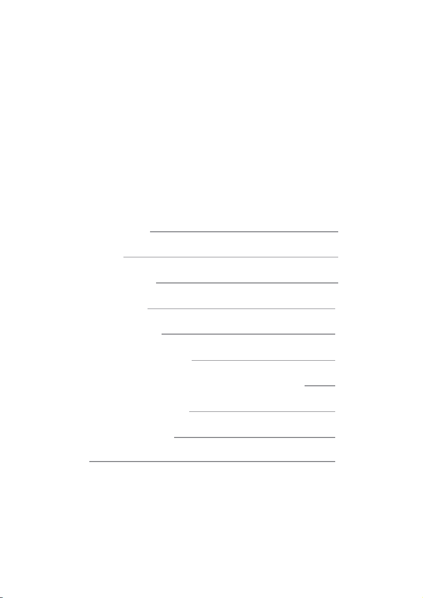
Introduction
The Grandia GD09 is a culmination of SilverStone’s decade-long experience in HTPC case design and manufacturing into a product
that every PC enthusiast can enjoy. The incredible efficiency in which it utilizes all available space results in a case that is close in
size externally to Micro-ATX based GD04 and GD05, yet capable of fitting most important full size standard components including
wider ATX motherboards (SSI-CEB) such as ROG or other gaming-centric models. All drive cages have been designed similarly to
those from the popular ML03 case to provide maximum flexibility in drive configuration without the need for additional adapters. For
cooling, all positive pressure and smooth airflow designs were retained from previous Grandia models while improvements were made
to filter access for even easier maintenance. With the GD09, there has never been a more attractively sized HTPC case that is as
capable and user-friendly. So whether one is looking to build an affordable or a powerful PC, this case can definitely satisfy both
ends of the requirement.
Specification
Material
Model
Motherboard
Drive Bay
Cooling System
Expansion Slot
Front I/O Port
Power Supply
Expansion Card
Limitation of CPU cooler
Dimension
Plastic front panel with faux aluminum finish, 0.8mm steel body
SST-GD09B (black)
SSI CEB, ATX, Micro ATX*
Exposed
Internal
Right
Rear
Top
Left
7 + 1
USB 3.0 x 2, audio x 1, MIC x 1
Standard PS2 (ATX)
220mm maximum, 180mm recommended
Support cards up to 12.2”, width restriction 5.25”
138mm
440mm (W) x 170mm (H) x 358mm (D), 26.8 liters
5.25" x 1 (compatible with 3.5” x 1 or 2.5” x 2)
3.5" x 2 (one compatible with 2.5”), 2.5” x1
1 x 120mm intake fan, 900rpm, 18dBA
1 x 120mm fan slot
2 x 80mm fan slot
Expansion card vent
1 x 120mm fan slot, compatible with 80mm fan
1
Page 4
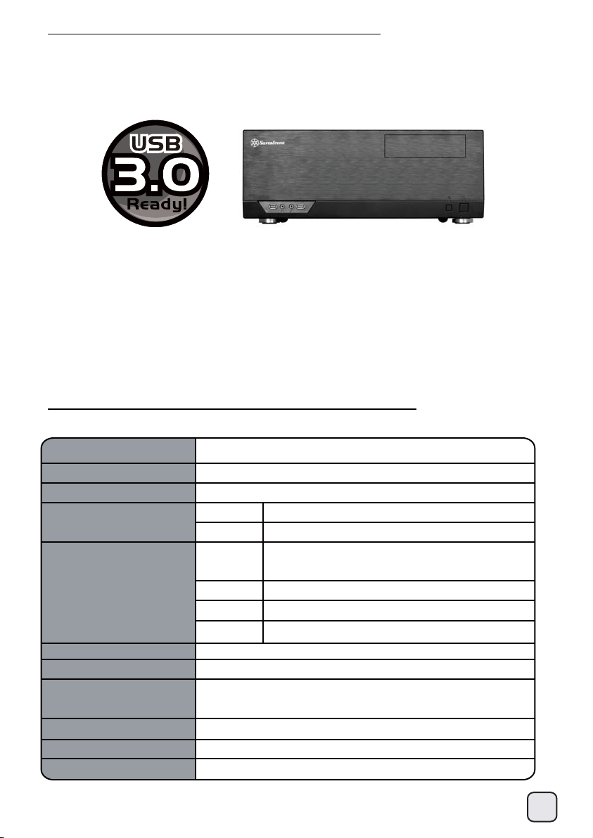
Disassemble Chart
TOP - COVER
5.25” DRIVE BAY X 1 OR
3.5” DRIVE BAY X 1 OR
2.5” DRIVE BAY X 2
FILTER
USB 3.0 X 2 + SPK + MIC
5.25” DRIVE BAY X 1
RESET - BUTTON
POWER - BUTTON
12025 FAN X 1 OR 8025 FAN (OPTION)
PS2 - PSU (OPTION)
EXPANSION SLOTS X 8
8025 FAN X 2 (OPTION)
12025 FAN X 1
12025 FAN X 1 (OPTION
FILTER
3.5” DRIVE BAY X 1 OR
2.5” DRIVE BAY X 1
PICTURE ITEM PURPOSE
SHOCK TANT - RING - YEL - GRAY
STANDOFF - 6 - 32 X 6.5H - 6 - 32
SCREW - I - 6 - 32 X 5 - BK
SCREW - P / W - M3 X 6 - BK
Anti-vibration rings
Motherboard standoff
Secure motherboard, PSU, 3.5” drives
Secure 3.5” hard drive tray
3.5” DRIVE BAY X 1
SCREW - P / W - M3 X 6 - BK
SCREW - PAN - 4 X 4.8H - 6 - 32 X 3.4 - NI
BUNCH - WIRE - TIES
Secure 2.5” drives
Secure 3.5” drives
Cable management
2
Page 5
Installation Chart
Before you begin, please make sure that you
(1) have all components collected
(2) check that all components do not have compatibility problems with each other or
with the case
(3) if possible, assemble the components outside the case first to make sure they are working
(4) keep the motherboard manual ready for reference during installation
(5) prepare a Philips screwdriver.
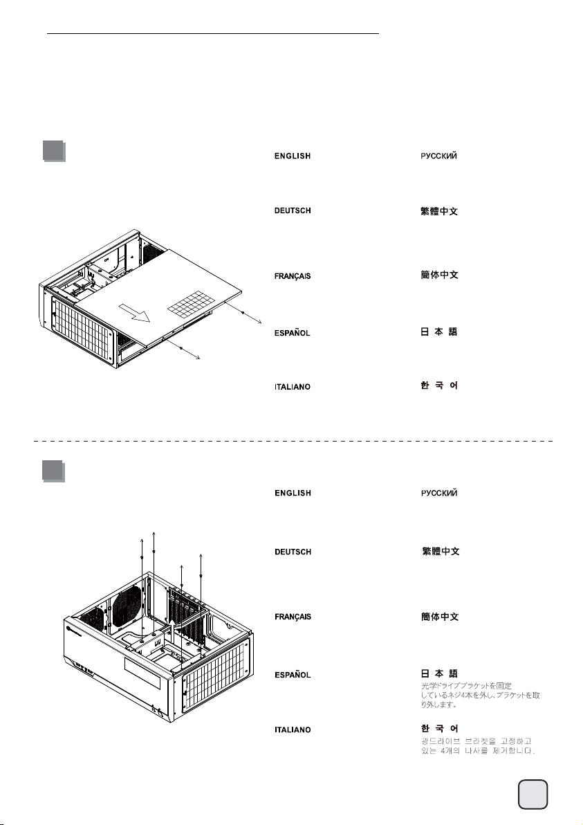
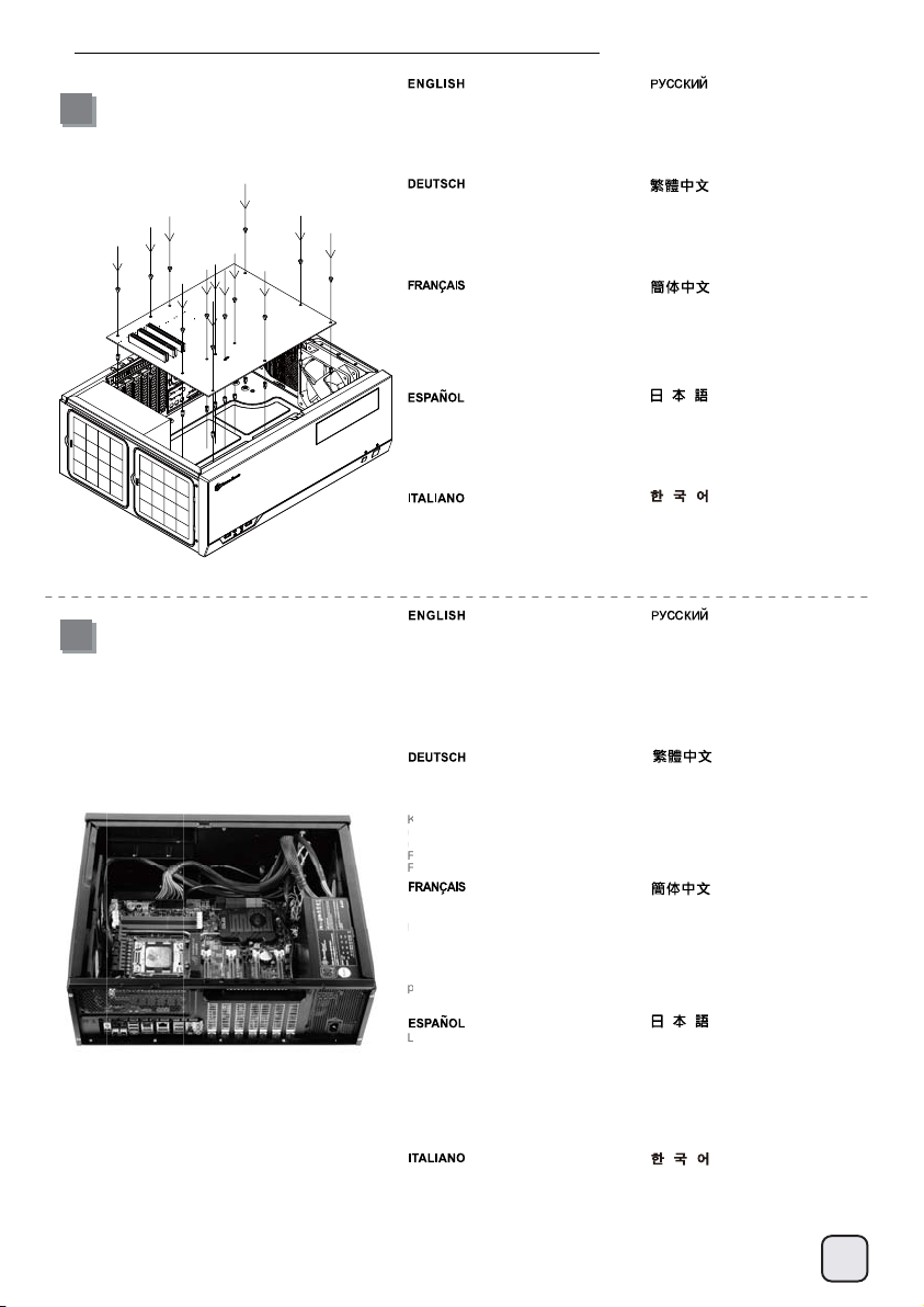
1
Unscrew screws from the rear of
the chassis then remove the top
cover
Ослабьте два винта на задней
панели корпуса и снимите
верхнюю крышку.
der Rückseite des Gehäuses,
entfernen Sie dann die obere
Abdeckung.
Dévissez les deux vis de l'arrière du
boîtier puis retirez le panneau
supérieur.
Afloje dos tornillos de la parte posterior
del chasis para retirar la cubierta
superior.
Allentare le due viti sul lato posterior
del telaio e poi rimuovere il coperchio
superiore.
取下上蓋螺絲,取下上蓋板Lösen Sie die beiden Schrauben von
取下上盖螺丝,取下上盖板
ケース後部のネジ2本をゆるめ
てからトップカバーを取り
外します。
섀시 후면에 있는 두 개의
나사를 푼 다음
상단 커버를 분리합니다.
2
Unscrew four screws from the
optical drive bracket to remove it
Lösen Sie die vier Schrauben,
welche den Schacht für das optische
Laufwerk halten, nehmen Sie den
Schacht heraus.
Открутите четыре шурупа,
удерживающих кронштейн
жесткого диска, и выньте
кронштейн.
鬆開光碟架4顆螺絲,卸下光碟架
Dévissez les quatre vis fixant le casier
du lecteur optique afin de le retirer
Desatornille cuatro tornillos que
sujetan el bracket del dispositivo óptico
y luego retírelo.
Svitare le 4 viti che tengono la staffa
del drive ottico e quindi rimuoverlo.
松开光盘架4颗螺丝,卸下光盘架
3
Page 6
Installation Guide
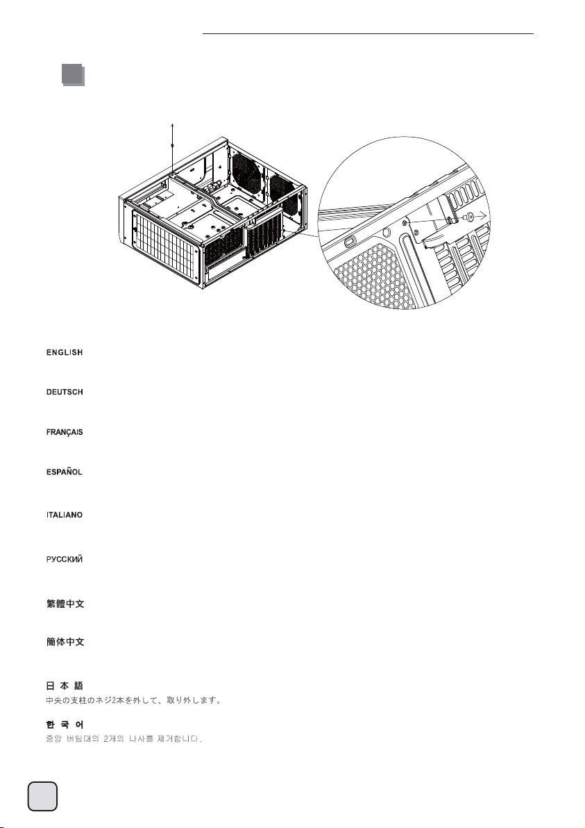
3
Unscrew two screws from the center brace to remove it
Lesen Sie die beiden Schrauben an der mittleren Halterung, nehmen Sie die Halterung heraus.
Dévissez les deux vis de la barre centrale afin de la retirer.
Desatornille dos tornillos del eje central para quitarlo.
Svitare le due viti del gancio centrale per rimuoverlo.
Открутите два шурупа на центральной скобе и выньте ее.
鬆開中支架2顆螺絲,卸下中支架
松开中支架2颗螺丝,卸下中支架
4
Page 7
Installation Guide
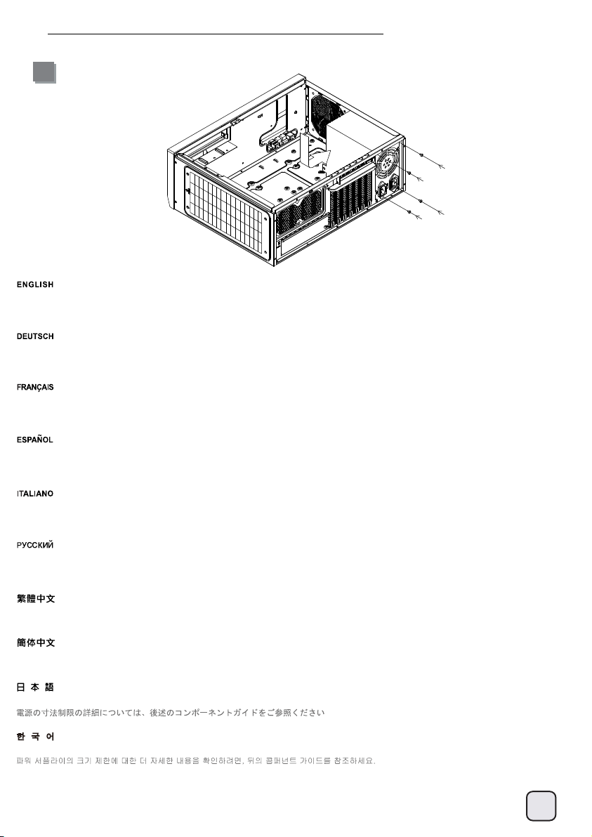
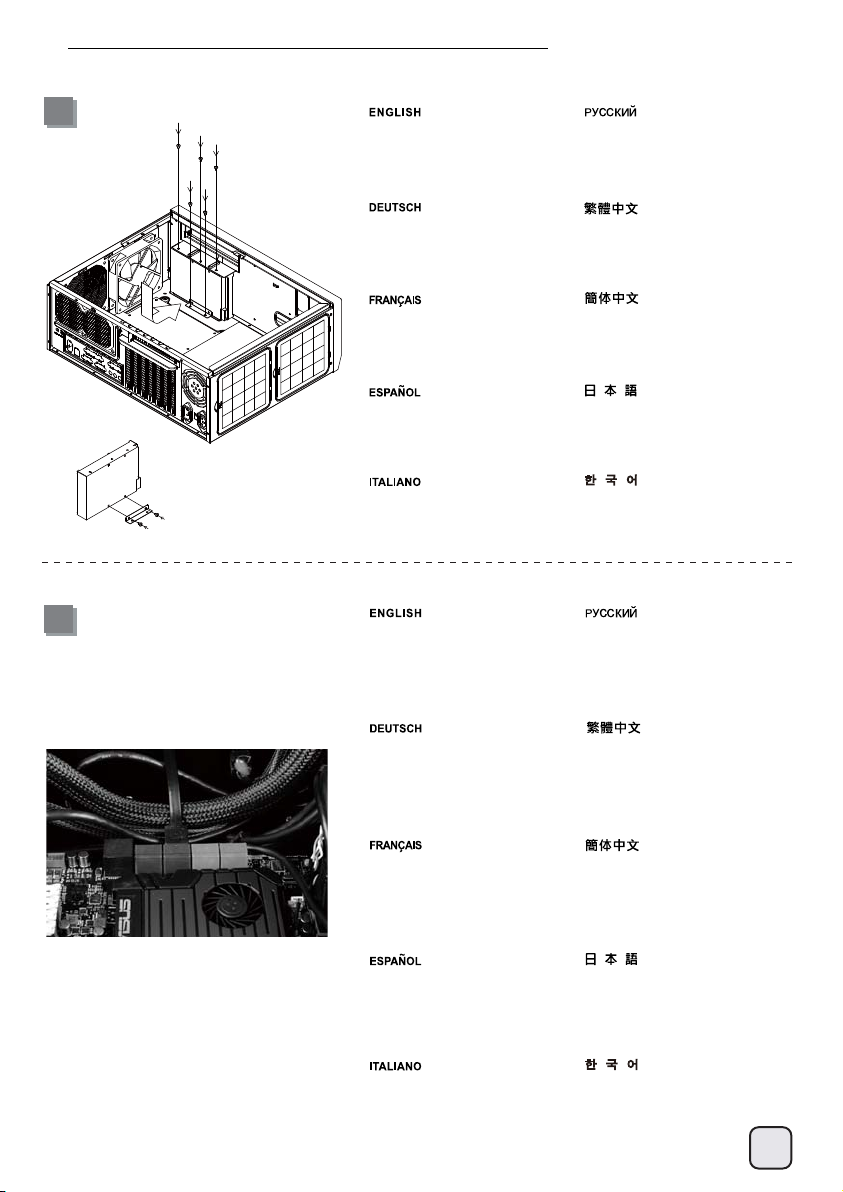
4
Install power supply into the case. If you use a power supply with 120mm fan or bigger, we recommend installing it with the fan facing left (outwards).
For more information regarding power supply size limitations, please refer to the component guide in later pages
Falls Sie ein Netzteil mit einem 120 mm-Lüfter (oder größer) verwenden, empfehlen wir eine Installation, bei der der Lüfter nach links (außen) zeigt.
Weitere Hinweise zur Größenbeschränkung bei Netzteilen finden Sie in den Komponentenhinweisen auf den folgenden Seiten.)
Si vous utilisez une source d'alimentation avec un ventilateur de 120mm ou plus, nous vous recommandons d'installer avec le ventilateur tourné
vers la gauche (vers l'extérieur).
Si usa una fuente de alimentación con un ventilador de 120mm o mayor, le recomendamos instalarlo con el ventilador hacia la izquierda
(hacia afuera). Para tener mas informacion sobre las limitaciones de tamano de la fuente de alimentacion, por favor consulte la guia de
componenetes que aparece en paginas posteriores.
Se si utilizza un alimentatore con ventola da 120 mm o più grande, si consiglia di installarlo con la ventola rivolta verso sinistra (verso l'esterno).
Per maggiori informazioni in merito alle limitazioni in dimensioni degli alimentatori installabili, fare riferimento alla guida nelle pagine seguenti.
При использовании блока питания со 120-мм и более мощным вентилятором мы рекомендуем устанавливать его, направленным влево
(наружу). Более подробную информацию об ограничениях на габариты блока питания вы найдете на следующих страницах руководства.
將電源供應器由上放入機殼內,如果有12cm或以上尺寸的風扇,我們建議朝左(外部)(關於電源供應器長度規格,請參考元件尺寸限制)
将电源供应器由上放入机壳内,如果有12cm或以上尺寸的风扇,我们建议朝左(外部)(关于电源供应器长度规格,请参考组件尺寸限制)
120mmまたはそれより大きいファンの付属した電源を使用される場合は、ファンが左側(外向き)になるように設置することを推奨します。
전원 공급장치에 120mm 이상의 팬이 있는 경우 팬이 정면 왼쪽(바깥쪽)을 향하도록 설치할 것을 권장합니다.
5
Page 8
Installation Guide
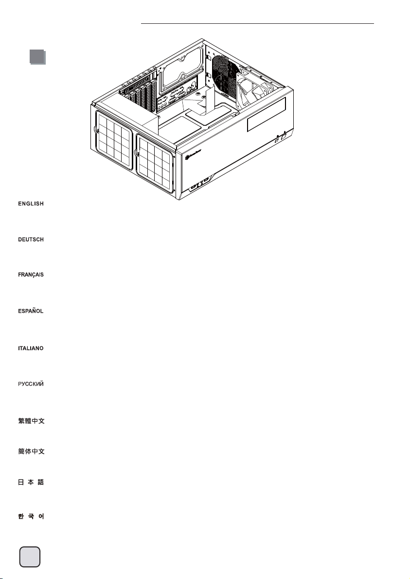
5
Insert the I/O shield included with your motherboard into the rear I/O slot on the case
Setzen Sie das mit Ihrem Motherboard gelieferte I/O-Blech in die Aussparungen an der Rückseite des Gehäuses ein,
installieren Sie anschließend das Motherboard im Gehäuse.
Insérez la plaque d'E/S inclus avec votre carte mère, puis installez la carte mère dans le boîtier
Inserte el protector de E/S incluido en su placa base, luego instale la placa base en la carcasa.
Installare la mascherina I/O inclusa con la scheda madre, quindi installare la mainboard nel case.
Установите заглушку для разъёмов задней панели материнской платы, прилагаемую к материнской плате,
затем установите материнскую плату в корпус.
將I/O彈片裝上機殼
将I/O弹片装上机壳
お持ちのマザーボードに付属のI/Oシールドを挿入してから、ケースの中にマザーボードを取り付けます。
메인보드와 같이 동봉된 I/O Shield 를삽입한 후, 메인보드를케이스에설치합니다.
6
Page 9
Installation Guide
d
K(2(4Fc
c
c
CdpdL
6
7
If required, install additional
motherboard standoffs onto the
motherboard tray, then install the
motherboard into the case and secure
with SCREW C
If required, install additional
motherboard standoffs onto the
motherboard tray, then install the
motherboard into the case and secure
with SCREW C
Si nécessaire, veuillez installer des
entretoises de carte mère
supplémentaires sur le plateau de la
carte mère, puis installer la carte mère
dans le boîtier et attachez-la avec la
VIS C.
Si es necesario, instale soportes
adicionales para placas base en la
bandeja de la placa base, luego
instale la placa base en la carcasa y
fíjela con TORNILLOS C
Se necessario, installare distanziatori
supplementari della scheda madre
cassetto della scheda madre, quindi
installare la scheda madre nel case e
fissarla con la VITE C
We recommend at this point to start
thinking about routing the cables
cleanly before connecting them to
the motherboard, cables include fan
cables, power supply 24pin cable,
CPU ATX 4pin/EPS12V 8pin, front
panel connectors, and front I/O
connectors
При необходимости установите
дополнительные опорные винты
на лоток системной платы, затем
установите системную плату в корпус
и закрепите с помощью винта C
請依需求將SCREW D 的主機板螺柱鎖
固於機殼,再將主機板裝入機殼,
用SCREW C 螺絲將其鎖固
请依需求将SCREW D 的主板螺柱锁固
于机壳,再将主板装入机壳,
用SCREW C 螺丝将其锁固
必要な場合は、マザーボードトレイに
追加のマザーボードスペーサーを取り
付けてから、ネジCでマザーボードをケ
ースに固定します。
필요할 경우 메인보드 트레이 위에
메인보드 스탠드오프를 추가 설치한 다음
메인보드를 케이스에 끼우고 나사 C로
고정하십시오.
Мы рекомендуем задуматься о
прокладке кабелей до их подключения
к материнской плате. Имеются в
следующие кабели: кабели
вентиляторов, 24-контактный силовой
кабель, 4-контактный ATX и
8-контактный EPS 12В кабели ЦП,
разъемы передней панели и передние
разъемы ввода/вывода.
виду
An diesem Punkt empfehlen wir Ihnen,
über eine saubere Verlegung der Kabel
nachzudenken, bevor Sie die Kabel an
das Motherboard anschließen. Zu den
Kabeln zählen Stromversorgungskabel
(24-polig), CPU ATX-Kabel
(4-polig)/EPS 12 V-Kabel (8-polig),
Frontblenden-Anschlusskabel sowie
Front-I/O-Kabel.
A ce stade nous recommandons de
commencer à organiser proprement
les câbles avant de les brancher à la
carte mère, câbles de ventilateurs,
connecteur 24pin de l'alimentation,
Connecteur ATX 4 pin/EPS12V 8pin
du processeur, connecteurs du
panneau frontal, et les connecteurs
des ports E/S frontaux.
Le recomendamos que en este punto
comience a enrutar los cables con
limpieza antes de conectarlos a la placa
base. El término “cables” incluye los
cables de los ventiladores, el cable de
24 pines de la fuente de alimentación,
el de 4 pines CPU ATX/8 pines EPS12V,
conectores del panel frontal y
conectores de E/S frontales.
A questo punto, si raccomanda di
pensare a come gestire la disposizione
dei cavi interni prima di connetterli alla
scheda madre. Si fa riferimento ai i cavi
delle ventole, all cavo dell’alimentatore
a 24 pin, al 4pin ATX ed EPS 12V 8 pin,
alle connessioni del pannello frontale
ed alle connessioni frontali I/O.
我們建議您可以在這時開始理線,
請先安插好ATX24Pin接線,
Front panel controller
與Front I/O
我们建议您可以在这时开始理线,
请先安插好ATX24Pin接线,
Front panel controller
与Front I/O
マザーボードにケーブルを接続する前に、
すっきりしたケーブルの取り回しを考え
始めるようお勧めします。これには、
ファンケーブル、電源24ピンケーブル、
CPU ATX 4ピン/EPS12V 8ピン、フロン
トパネルコネクタ、およびフロントI/Oコ
ネクタが含まれます。
이번 단계에서부터 케이블 정리에대해
생각해주시기를권장합니다.팬케이블,
파워 서플라이 24핀케이블, CPU,
ATX 4핀/EPS 12V 8pin,전면패널 커넥터,
전면 IO 커넥터등이 대상이 됩니다.
7
Page 10
Installation Guide
8
Install 2.5” drive onto the floor of the case and secure with screws. Make sure drive connectors are facing the rear of the case
Installieren Sie das 2,5 Zoll-Laufwerk im unteren Teil des Gehäuses; anschließend mit Schrauben fixieren. Stellen Sie sicher,
dass die Laufwerksanschlüsse in Richtung Gehäuserückseite zeigen
Installez le lecteur 2,5" dans la partie inférieure du châssis et attachez-le avec des vis. Vérifiez que les connecteurs
pour lecteur font face à l'arrière du châssis
Instale el dispositivo de 2,5" en el suelo de la carcasa y fíjelo con tornillos. Asegúrese de que los conectores de los dispositivos se
orientan hacia la parte trasera de la carcasa.
Installare l’unità 2.5” sulla base del case e fissarla con le viti. Assicurarsi che connettori dell'unità siano rivolti verso la parte posteriore del case
Установите 2,5-дюймовый дисковод в нижней части корпуса и закрепите его винтами. Разъемы подключения диска должны
быть обращены к задней панели корпуса
將2.5”硬碟裝入底板,並鎖固,接頭朝後
将2.5”硬盘装入底板,并锁固,接头朝后
2.5”ドライブをケース底部に設置しネジで固定します。ドライブのコネクタがケース後部に向いていることを確認します。
2.5”ドライブをケース底部に設置しネジで固定します。ドライブのコネクタがケース後部に向いていることを確認します。
8
Page 11
Installation Guide
9
10
Use small bracket included in the
accessories box to install 3.5” drive
beneath the optical drive area
Verwenden Sie die mitgelieferte
kleine Halterung zur Installation des
3,5-Zoll-Laufwerks unter dem Bereich
des optischen Laufwerks
Utiliser le petit support fourni dans la
boîte d'accessoires pour installer le
disque 3,5" sous la zone de lecteur
optique.
Use el bracket pequeño incluido en
la caja de accesorios para instalar el
dispositivo de 3,5” bajo la zona del
dispositivo óptico
Utilizzare la piccola staffa inclusa nella
scatola degli accessori per installare
l’unità da 3,5" sotto la zona dell’unità
ottica
Depending on your configuration,
pre-connect any SATA cables to
your motherboard before installing
expansion cards
Для установки 3,5-дюймового диска
под оптическим приводом используйте
малый кронштейн из пакета
аксессуаров
使用零件包內附小架,
安裝光碟機下方的3.5”硬碟
使用零件包内附小架,
安装光驱下方的3.5”硬盘
3.5”ドライブは、アクセサリボックス
内の小型ブラケットを使って、
光学ドライブの下方に設置します。
액세서리 상자에 들어 있는 소형 브래킷을
이용해서 광 드라이브 영역 아래쪽에
3.5" 드라이브를 설치하십시오.
В зависимости от конфигурации,
перед установкой карт расширения
подключите к системной плате
кабели SATA
Je nach Konfiguration schließen
Sie jegliche SATA-Kabel an Ihrem
Motherboard an, bevor Sie
Erweiterungskarten installieren
Selon votre configuration,
veuillez pré-brancher les câbles
SATA de votre carte mère avant
d'installer des cartes d'extension.
Dependiendo de su configuración,
pre-conecte cualquier cable SATA
a su placa base antes de instalar
las tarjetas de expansión
In base alla configurazione,
pre-collegare tutti i cavi SATA alla
scheda madre prima di installare le
schede di espansione
視配置而定,介面卡可能擋住主機板
的SATA插槽,建議您先數好需要的
SATA線材,這時先插好
视配置而定,适配卡可能挡住主板
的SATA插槽,建议您先数好需要的
SATA线材,这时先插好
ご使用の構成に依存しますが、
拡張カード装着の前に必要な
SATAケーブルを前もってマザーボー
ドに接続しておきます。
사용자의 구성에 따라서는 확장 카드를
설치하기 전에 메인보드에 SATA
케이블을 미리 연결해야 합니다.
9
Page 12

Installation Guide
11
Remove expansion slot covers as required, install expansion cards and secure with screws
Entfernen Sie die Abdeckungen des Erweiterungssteckplatzes wie erforderlich; installieren
Sie die Erweiterungskarten und sichern Sie mit Schrauben
Retirez les caches des fentes d’extension si nécessaire, installez les cartes d'extension et attachez-les avec des vis.
Retire las cubiertas de los zócalos de expansión según lo necesite, instale tarjetas de expansión y fíjelas con tornillos
Rimuovere le coperture degli alloggi di espansione come necessario, installare schede di espansione e fissarle con le viti
При необходимости снимите крышки слотов расширения, установите карты расширения и закрепите винтами
先取下擴充槽上的蓋板與擋片,再將擴充卡裝入,並以內附螺絲鎖固。
先取下扩展槽上的盖板与挡片,再将扩充卡装入,并以内附螺丝锁固。
必要に応じて拡張スロットカバーを外し、拡張カードを装着してからネジで固定します。
확장 슬롯 커버를 분리한 다음, 필요한 확장 카드를 설치하고 제공된 나사를 사용하여 고정시키십시오.
10
Page 13

Installation Guide
12
Install hard drive and optical drive to optical drive bracket as required. For more details on installation of this bracket, please refer to the
guides in the later pages
Installieren Sie Festplatte und optisches Laufwerk wie erforderlich in der Halterung für optische Laufwerke. Weitere Einzelheiten zur
Installation dieser Halterung entnehmen Sie bitte den Anleitungen auf späteren Seiten
Installez le disque dur et le lecteur optique sur le support de lecteur optique si nécessaire. Pour plus de détails sur l'installation de ce support,
veuillez consulter les guides dans les pages suivantes.
Instale un disco duro o dispositivo óptico en el bracket para dispositivo óptico según lo precise. Para más detalles sobre la instalación
de este bracket, por favor consulte las guías de páginas posteriores
Installare il disco rigido e l’unità ottica al supporto dell'unità ottica come necessario. Per altri dettagli sull'installazione di questa staffa,
di consultare le guide nelle pagine successive
Установите жесткий диск и оптический привод соответствующим образом на кронштейн оптического привода. Подробная информация
по установке этого кронштейна дана в руководствах, приведенных далее
將硬碟與光碟安裝上光碟架,如果要用向下相容的方式安裝,請參考說明
将硬盘与光盘安装上光盘架,如果要用向下兼容的方式安装,请参考说明
必要に応じて、光学ドライブ・ブラケットにハードディスクドライブと光学ドライブをインストールします。
このブラケットのインストールに関する詳細は、後述ページにおけるガイドをご参照ください。
필요할 경우 하드 드라이브와 광 드라이브를 광 드라이브 브래킷에 설치하십시오. 이 브래킷 설치에 관한 자세한 내용은
다음 페이지의 지시사항을 참조하십시오.
11
Page 14

Installation Guide
13
14
Remove 5.25” drive bay cover
if needed
Entfernen Sie die Abdeckung des
5,25-Zoll-Laufwerkseinschubs,
falls erforderlich
Retirez le couvercle de la
baie de lecteur 5,25" si
nécessaire.
Retire la cubierta de la bahía de
dispositivos de 5,25” si lo necesita
Rimuovere la copertura
dell’alloggio unità 5,25",
se necessario
Reinstall the center brace back
into the case
Bauen Sie die mittlere Halterung
wieder in das Gehäuse ein.
При необходимости снимите
крышку отсека 5,25-дюймового
диска
移除需要安裝的5.25”檔板
移除需要安装的5.25”檔板
必要ならば5.25”ドライブ
ベイカバーを取外します。
필요할 경우 5.25" 드라이브
베이 커버를 벗기십시오.
Вставьте центральную скобу
обратно в корпус.
安裝中支架
12
Réinstallez la barre central
dans le boîtier.
Reinstale el eje central
en la carcasa.
Reinstallare il gancio centrale
nel case.
安装中支架
Page 15

Installation Guide
Sc
Ne
La
Bra
et d
s
à 9
e
15
16
Reinstall the optical drive bracket
back into the case
Installieren Sie die Halterung für
optische Halterungen wieder im
Gehäuse
Réinstallez le support du lecteur
optique dans le boîtier.
Reinstale el bracket para
dispositivo óptico de nuevo en
la carcasa
Reinstallare il supporto dell'unità
ottica sul telaio
Connect all data and power cables
for installed drives. 90 degree
angled connectors are recommended
for better space saving
Установите кронштейн оптического
привода в корпус
將光碟架裝回機殼
将光盘架装回机壳
光学ドライブ・ブラケッ
トをケースに戻します。
광 브라이브 브래킷을 케이스에
도로 끼우십시오.
Подключите все кабели данных и
питания к установленным приводам.
Для оптимального использования
объема корпуса рекомендуется
использовать Г-образные разъемы
Schließen Sie alle Daten- und
Netzkabel für die installierten
Laufwerke an. 90 Grad
Branchez tous les câbles de données
et d'alimentation pour les lecteurs
installés. Des connecteurs coudés
in
à 90 degrés sont recommandés pour
mieux économiser de l'espace.
mi
Conecte todos los cables de datos
y potencia para los dispositivos
instalados. Los conectores en ángulo
de 90 grados se recomiendan para
ahorrar más espacio
Collegare tutti i cavi dati e di
alimentazione per le unità installate.
Sono raccomandati connettori ad
angolo di 90 gradi per un migliore
risparmio di spazio
安裝所有Drive Bay的連接線,
無論是排線或是電源線,我們都建議
最好用90度的,比較省空間
安装所有Drive Bay的连接线,
无论是扁平电缆或是电源线,我们都建
议最好用90度的,比较省空间
装着されたドライブの用のデータ
および電源ケーブルを全部接続します。
より優れたスペース節約には、90度ア
ングルコネクタがお勧めです。
설치된 드라이브를 위한 모든 데이터와
전원 케이블을 연결하십시오. 좁은
공간의 경우 90도 각도의 커넥터
사용을 권장합니다.
13
Page 16

Installation Guide
17
Reinstall top cover back onto the case to complete installation
Bringen Sie zum Abschluss der Installation die obere Abdeckung wieder am Gehäuse an
Réinstallez le couvercle supérieur sur le boîtier pour terminer l'installation.
Reinstale la cubierta superior de nuevo en la carcasa para completar la instalación
Reinstallare la copertura superiore sul case per completare l'installazione
Установите верхнюю крышку на корпус
裝回上蓋板,完成組裝
装回上盖板,完成组装
上部カバーをケースに戻すと、インストールは完了です。
상단 커버를 케이스에 도로 씌우면 설치가 완료됩니다.
14
Page 17

Connector definition
(1) Front panel connector installation no polarity, so they can be connected
in any orientation
Power switch and reset switch installation guide:
Please refer to the motherboard manuals for the motherboard’s “Front Panel Connector” or “System Panel Connector” pin definitio
Power switch and reset switch have no polarity, so they can be connected in any orientation.
Bitte suchen Sie in der Motherboard-Dokumentation nach der Pinbelegung der Anschlüsse des Frontbedienfeldes („Front Panel Conne
oder „ System Panel Connectors“). Ein-/Austaste und Rücksetztaste benötigen keine bestimmte Polarität, können daher beliebig (o
und - zu achten) angeschlossen werden.
Veuillez-vous référer au manuel de votre carte mère pour la description des broches "des connecteurs du panneau frontal" et des
"des connecteurs du panneau système". Les interrupteurs d'allumage et de réinitialisation ne possède pas de polarité, donc ils peuvent être
branché dans les deux sens.
Por favor, consulte en los manuales de la placa base la configuración de pines del “Conector de panel frontal” ó “Conector de panel de sistema”
de su placa base. Los interruptores de encendido y reseteo no tienen polaridad, luego se pueden conectar con cualquier orientac
Fare riferimento al manuale della scheda madre nella sezione “Connettori del pannello frontale” o “Connettori del pannello di sistema”. Power
switch e reset switch non hanno polarità, posso essere pertanto connessi con qualsiasi orientamento.
Описание контактов разъемов приведены в разделах “Разъемы передней панели” или “Разъемы системной панели” руководства
пользователя материнской платы. Выключатель питания и кнопка перезагрузки не имеют полярности, поэтому их можно подключать
в любой ориентации.
메인보드 매뉴얼의 전면패널 커넥터 혹은 시스템패널 커넥터 핀을 참조하기 바랍니다. 파워 스위치와 리셋 스위치는 극성이 없어 어떤
방향으로 설치해도 무방합니다.
マザーボードの「フロントパネルコネクタ」または「システムパネルコネクタ」のピン配列についてはマザーボードマニュアルを参照してください。
電源スイッチとリセットスイッチに極性はないので、いずれの方向でも接続できま。
請參考主機說明書的Front Panel Connectors安裝Pin Define,將Connector插上;Power Switch 與Reset Switch並無正負極性之分,
反插正插都不影響功能性。
请参考主机说明书的Front Panel Connectors安装Pin Define,将Connector插上;Power Switch 与Reset Switch并无正负极性之分,
反插正插都不影响功能性。
15
Page 18

Connector definition
(2) LED indicators installation guide
Please refer to the motherboard manuals for the motherboard’s “Front Panel Connector ” or “System Panel Connector” pin definition.; the white/black
wires are negative while other colors are positive wires. The Power LED wires are separate pins for compatibility with different motherboard pin
definition so please make sure they are connected in the right polarity by referring to your motherboard manual.
Bitte suchen Sie in der Motherboard-Dokumentation nach der Pinbelegung der Anschlüsse des Frontbedienfeldes („Front Panel Connectors“ oder „
System Panel Connectors“). Die weißen/ schwarz Adern sind negativ (-), die farbigen Adern positiv (+).Die Kabel für die Betriebsanzeige-LED sind
zur Kompatibilität mit unterschiedlichsten Motherboards einzeln, nicht als kompletter Stecker ausgeführt. Achten Sie hier bitte auf die richtige
Polarität, lesen Sie in der Dokumentation Ihres Motherboards nach.
Veuillez-vous référer au manuel de votre carte mère pour la description des broches "des connecteurs du panneau frontal" et des broches "des connecteurs du panneau
système". Les câbles colorés en blanc/noir sont négatifs alors que ceux d'une autre couleur sont positifs. Les câbles de la LED Power sont séparés afin d'être compatible
avec différentes cartes mères, donc vérifiez bien qu'ils sont branchés avec la bonne polarité en vous référant au manuel de votre carte mère
Por favor, consulte en los manuales de la placa base la configuración de pines del “Conector de panel frontal” ó “Conector de panel de sistema” de
su placa base. Los cables de color blanco/negro son negativos mientras que los de color son positivos. Los cables LED de potencia tienen pines
separados para compatibilidad con diferentes definiciones de pines de la placa base luego por favor, asegúrese de que están conectados en la
polaridad correcta consultando el manual de su placa base.
Fare riferimento al manuale della scheda madre nella sezione “Connettori del pannello frontale” o “Connettori del pannello di sistema”. I cavi di
colore bianco/nero sono il polo negativo, mentre quelli di colore diverso il positivo.
Описание контактов разъемов приведены в разделах “Разъемы передней панели” или “Разъемы системной панели” руководства
пользователя материнской платы. Белые/черный провода - отрицательной полярности, цветные провода - положительной полярности.
Провода светодиодного индикатора питания имеют отдельные контакты для совместимости с различными типами контактов материнских
плат, поэтому обратитесь к руководству пользователя материнской платы и убедитесь, что
메인보드 매뉴얼의 전면패널 커넥터 혹은 시스템패널 커넥터 핀을 참조하기 바랍니다. 하얀/검은선의 경우 음극이며, 다른 색의 경우
양극입니다. 파워 LED 선은 분리되어 다양한 메인보드에서 동작할 수 있도록 되어 있습니다. 그러므로 메인보드 매뉴얼을 참조하여 올바를
극성을 주의해 선택하시기 바랍니다.
マザーボードの「フロントパネルコネクタ」または「システムパネルコネクタ」ピン配列についてはマザーボードマニュアルを参照してください。
白/黑色のリード線はマイナスで、色の着いたリード線がプラスです。電源LEDリード線は種々のマザーボードピン定義と互換性を持たせるため分離されたピ
ンとなっているので、ご使用のマザーボードマニュアルを参照して、適切な極性に接続されるようお確かめください。
請參考主機說明書的Front Panel Connectors安裝Pin Define,將Connector插上; 白/黑色線的部分為負極,彩色線的部分是正極。
Power LED為了適應各主機板的不同, 特別設計為散Pin樣式,請安心使用。
请参考说明书的Front Panel Connectors安装Pin Define,将Connector插上;白/黑色线的部份为负极,彩色线的部份为正极。
Power LED为了适应主机板的不同, 特别设计为散Pin样式,请安心使用。
полярность соблюдена.
16
Page 19

Connector definition
(3) Front I/O connector guide
Below are the front I/O connectors pin definition, please also check your motherboard manual to cross reference with motherboard’s
front I/O pin headers. SilverStone’s I/O connectors are in block type to simplify installation.
Nachstehend finden Sie die Pinbelegung der vorderen E/A-Anschlüsse; bitte gleichen Sie zudem das Handbuch Ihres Motherboards mit
den vorderen E/A-Pinzuweisungen ab. SilverStones E/A-Anschlüsse befinden sich zur Vereinfachung der Installation in Blockart.
Au dessous de la description des broches des ports d'E/S, veuillez aussi vérifier sur le manuel de votre carte mère de manière croisée
que les broches sont correctement placées. Les connecteurs d'E/S de SilverStone sont en bloc pour en simplifier leur installation.
A continuación tiene la definición de pines de los conectores frontales de E/S, también debe consultar el manual de su placa base para c
omprobar la referencia de los pines para E/S frontales. Los conectores de E/S de SilverStone son de bloque para simplificar la instalación.
Di seguito lo schema delle connessioni I/O frontali, confrontare lo schema con quanto riportato sul manuale della scheda madre per
effettuare una controllo incrociato. I connettori I/O Silverstone, per semplificare l’installazione, sono del tipo “a blocco”.
Ниже приведено описание контактов передних разъемов ввода/вывода. Обратитесь также к руководству пользователя материнской
платы за описанием передних разъемов ввода/вывода типа "пин-хедер". Разъемы ввода/вывода "SilverStone" - блочного типа, что
облегчает сборку.
아래는 전면 I/O 커넥터의 핀 설정이며, 메인보드 매뉴얼을 참조해 메인보드의 전면 I/O 핀 헤더와 맞추어 설치합니다.
Silverstone의 I/O 커낵터는 블록 타이브로 구성되어 설치를 간편화 했습니다.
以下はフロントI/Oコネクタピン配列ですが、お持ちのマザーボードのフロントI/Oピンヘッダは、マザーボードマニュアルをご参照ください。
シルバーストーンのI/Oコネクタは、インストールの容易なブロックタイプになっています。
下表為Front I/O Connectors的Pin Define,請參閱主機板說明書的各Front I/O Connectors Pin Define一一核對。
Front I/O Connectors完全採用集合Pin方式以簡化安裝。
下表为Front I/O Connectors的Pin Define,请参阅主机板说明书的各Front I/O Connectors Pin Define一一核对。
Front I/O Connectors完全采用集合Pin方式以简化安装。
USB3.0 CONNECTOR
PIN 1
VBUS
INTA_P2_SSRX-
INTA_P2_SSRX+
GND
INTA_P2_SSTX-
INTA_P2_SSTX+
GND
INTA_P1_D-
INTA_P1_D+
ID
PIN 10
PIN 19
VBUS
INTA_P2_SSRX-
INTA_P2_SSRX+
GND
INTA_P2_SSTX-
INTA_P2_SSTX+
GND
INTA_P2_D-
INTA_P2_D+
HD AUDIO CONNECTOR
AUD GND
PRESENCE
SENSE1_RETURN
PIN
SENSE2_RETURN
PIN 11
PORT1L
PORT1R
PORT2R
SENSE_SEND
PORT2L
PIN
17
Page 20

Component size limitations
The GD09 was designed to be compatible with standard sized or some larger
components, please refer to the following guidelines for component selection
and future upgrade considerations.
(1) CPU cooler height limitation
138MM
(A)
8MM
341MM
(B)
170MM
88MM
A. The GD09 has 138mm height limitation for CPU cooler and clearance of 8mm beyond the motherboard. If no optical drive is installed,
there is 170mm of room from the front panel to the motherboard edge.
B. The clearance below the optical drive is 88mm.
The total distance from the front optical drive opening to the rear of the motherboard is 348mm, so if you know how long the optical drive is,
then you can easily calculate the available area with the optical drive installed.
A. Das GD09 hat eine Höhenbeschränkung von 138 mm bei CPU-Kühlern und einen Abstand von 8 mm jenseits des Motherboards.
Falls kein optisches Laufwerk installiert wird, gibt es einen Freiraum von 170 mm Platz zwischen Frontblende zur Kante des Motherboards.
B. Der Abstand unter dem optischen Laufwerk beträgt 88 mm.
Der Gesamtabstand zwischen Öffnen des vorderen optischen Laufwerks und der Rückseite des Motherboards beträgt 348 mm; falls Sie also
wissen, wie lang das optische Laufwerk ist, können Sie den verfügbaren Platz mit installiertem optischem Laufwerk einfach berechnen.
A. Le GD09 a une limitation de hauteur de 138mm pour le refroidisseur de CPU et un espace libre de 8mm au-delà de la carte mère. Si aucun
lecteur optique n'est installé, il y a 170mm d'espace à partir du panneau avant jusqu'au bord de la carte mère.
B. L'espace libre en dessous du lecteur optique est 88mm.
La distance totale de l'ouverture avant du lecteur optique à l'arrière de la carte mère est 348 mm, donc si vous connaissez la longueur du lecteur
optique, alors vous pouvez facilement calculer la surface disponible avec le lecteur optique installé.
A. La GD09 tiene una limitación de altura de 138mm para el disipador de la CPU y un espacio libre de 8mm más allá de la placa base. Si no se
instalan dispositivos ópticos, existe un espacio de 170mm de espacio desde el panel frontal hasta el borde de la placa base.
B. El espacio libre necesario bajo el dispositivo óptico es de 88mm.
La distancia total desde la abertura del dispositivo óptico frontal hasta la parte posterior de la placa base es de 348mm, luego si conoce la longitud
del dispositivo óptico, podrá calcular fácilmente el espacio disponible con el dispositivo óptico instalado.
A. GD09 ha una limitazione in altezza di 138 mm per il dispersore di calore CPU ed uno spazio libero di 8 mm al di là della scheda madre. Se non
è installata alcuna unità ottica, c’è uno spazio di 170 mm dal pannello frontale al bordo della scheda madre.
B. Lo spazio libero sotto l'unità ottica è di 88 mm.
La distanza totale dall'apertura frontale dell’unità ottica ala parte della scheda madre è 348 mm, quindi se si sa quanto à lunga l'unità ottica si può
facilmente calcolare l'area disponibile quando l'unità ottica è installata.
A. Корпус GD09 имеет ограничение по высоте 138-мм для системы охлаждения процессора и зазор 8-мм над системной платой. Если
оптический привод не устанавливается, остается пространство 170-мм от края системной платы.
B. Зазор под оптическим приводом составляет 88-мм.
Общее расстояние от переднего отверстия для оптического привода до задней стороны системной платы составляет 348-мм, поэтому
если вам известна длина оптического привода, вы можете легко рассчитать доступное пространство при установленном оптическом
приводе.
,
18
Page 21

Component size limitations
A. GD09 모델의 경우 CPU 쿨러의 높이가 138mm로 제한되며 메인보드까지 8mm의 여유가 있습니다. 광 드라이브를 설치하지 않은 경우 전면
패널에서 메인보드 가장자리까지의 공간은 170mm입니다.
B. 광 드라이브 아래쪽 여유 공간은 88mm입니다.
광 드라이브 전면 구멍에서 메인보드 후면까지의 총 길이는 348mm이며 광 드라이브의 길이를 알고 있을 경우 광 드라이브 설치에 이용할 수 있는
공간을 쉽게 계산할 수 있습니다.
A. GD09には、CPUクーラー高さ制限およびマザーボード上方限度8mmの余裕があります。光学ドライブをインストールしない場合、
フロントパネルからマザーボード端まで170mmの余地があります。
B. 光学ドライブ下方の余地は88mmです。
フロントの光学ドライブからマザーボード後部までの距離は合計で348mmであるので、光学ドライブの長さが既知であれば、光学ドライブにインス
トール後に利用できるスペースを簡単に計算することができます。
A. Cooler限高是138mm,Cooler外源允許超出主機板上邊界8mm;不安裝光碟機的話前邊界為距離主機板後邊170mm
B. 而光碟機下方涵蓋的限高為88mm
光碟機表面距離主機板後邊348mm,你可以先知道光碟機本身長度是多少來判斷光碟機蓋住主機板的區域
A. Cooler限高是138mm,Cooler外源允许超出主板上边界8mm;不安装光驱的话前边界为距离主板后边170mm
B. 而光驱下方涵盖的限高为88mm
光驱表面距离主板后边348mm,你可以先知道光驱本身长度是多少来判断光驱盖住主板的区域
(C)
C. The illustration shows a SilverStone AR02 CPU cooler installed on a LGA115X platform with a 170mm long optical drive mounted.
AR02’s fan had to be installed on the rear of the heatsink to exhaust air toward the back of the case. If no optical drive was installed, then the fan can
be installed facing the front drawing air into the heatsink. For both fan configurations, GD09’s center brace barely clears AR02’s heatsink.
C. Die Abbildung zeigt einen auf einer LGA115X-Plattform mit montiertem 170 mm langem optischem Laufwerk installierten SilverStone CPU-Kühler
AR02. Der Lüfter des AR02 muss an der Rückseite des Kühlkörpers installiert sein, damit Luft Richtung Gehäuserückseite ausgegeben wird. Falls kein
optisches Laufwerk installiert ist, kann der Lüfter so installiert werden, dass er nach vorne zeigt und die Luft in den Kühlkörper zieht. Bei beiden
Lüfterkonfigurationen räumt die mittlere Klammer des GD09 knapp den Kühlkörper des AR02.
C. L'illustration montre un refroidisseur de CPU SilverStone AR02 installé sur une plate-forme LGA115X avec un lecteur optique de 170mm. Le
ventilateur du AR02 devait être installé à l'arrière du dissipateur thermique pour évacuer l'air vers l'arrière du boîtier. Si aucun lecteur optique n'a été
installé, le ventilateur peut alors être installé face à l'entrée frontale de l'air dans le dissipateur thermique. Pour les deux configurations de ventilation,
le centre du GD09 passe à peine le dissipateur thermique de AR02.
C. La ilustración muestra un disipador de CPU AR02 de SilverStone instalado en una plataforma LGA115X con un dispositivo óptico de 170mm de
largo instalado. El ventilador del AR02 debe instalarse en la parte posterior del disipador hacia el aire de salida de la parte posterior de la carcasa.
Si no se instalan dispositivos ópticos, entonces el ventilador se puede instalar orientado frente al aire de salida frontal hacia el disipador. Para ambas
configuraciones del ventilador la abrazadera central de la GD09 apenas deja espacio para el disipador AR02.
C. L'illustrazione mostra un dispersore di calore CPU SilverStone AR02 installato su una piattaforma LGA115X con una unità ottica lunga 170 mm. La
ventola di AR02 deve essere installata sul retro del dissipatore di calore per scaricare l'aria verso il retro del case. Se non è installata alcuna unità ottica,
la ventola può essere installata rivolta verso la parte anteriore aspirando l'aria dal dissipatore di calore. Per entrambe le configurazioni della ventola, il
supporto centrale di GD09 libera a malapena il dissipatore di calore di AR02.
C. На иллюстрации показана система охлаждения процессора SilverStone AR02 на платформе LGA115X с установленным оптическим
приводом длиной 170-мм. Вентилятор AR02 следует установить на задней части радиатора для вытяжки воздуха к задней панели корпуса.
Если оптический привод не устанавливается,
потока на радиатор. В обеих конфигурациях вентилятора центральный кронштейн корпуса GD09 просто освобождает радиатор AR02.
вентилятор можно установить направленным на лицевую панель для направления воздушного
19
Page 22

Component size limitations
C. 이 그림은 170mm 길이의 광 드라이브가 장착된 LGA115X에 설치된 SilverStone AR02 CPU 쿨러의 모습입니다. 공기가 케이스 뒤쪽으로
배기되도록 AR02 팬을 방열판 후면에 설치해야 했습니다. 광 드라이브가 설치되지 않은 경우 전면을 향하게 팬을 설치하여 공기를 방열판으로
끌어들일 수 있습니다. 두 가지 팬 구성 모두에서 GD09의 중앙 죔쇠가 AR02의 방열판을 건드리지 않고 간신히 지나갈 정도입니다.
C. 図には170mm長の光学ドライブをインストールしたLGA115Xプラットホームに設置されたSilverStone AR02 CPUクーラーが示されています。
AR02のファンは、ケース後方へ空気を排出するよう、ヒートシンク後方に設置する必要があります。光学ドライブをインストールしない場合、
ファンはフロントに向かってヒートシンクに空気を吸い込むよう設置できます。双方のファン構成では、GD09のセンターブレースは、ぎりぎり
でAR02のヒートシンクの余地に収まります。
C. 我們模擬安裝使用AR02安裝在LGA115X平台上,使用170mm的光碟機可能要把風扇安裝在Cooler後面用抽風的方式安裝,如果沒有裝光碟機,風扇可以
一般的裝在前面,而中支架確實很粗大,安裝AR02後,鰭片應該會壓在中支架下方
C. 我们模拟安装使用AR02安装在LGA115X平台上,使用170mm的光驱可能要把风扇安装在Cooler后面用抽风的方式安装,如果没有装光驱,风扇可以
一般的装在前面,而中支架确实很粗大,安装AR02后,鳍片应该会压在中支架下方
(2) Power supply limitations
180MM
(A)
A: Depth limitation
The maximum PSU depth is 180mm if 120mm fan on the left side of the case and bottom 2.5” drives are installed. 180mm full modular PSUs such
as SilverStone’s Strider Gold Evolution models have connectors that interferes with larger fans so only 80mm fan can be installed in this incidence.
If no fan or 2.5” drives are required, then longer PSUs can be installed.
B: Cable length recommendations
Below is a table of recommend cable length based off of common retail power supplies. Please make sure that the power supply you want to use
has long enough cables to fit the below recommendations or you can also choose to purchase additional power cable extensions:
A: Beschränkung der Tiefe:
Die maximale Netzteiltiefe beträgt 180 mm, wenn ein 120-mm-Lüfter an der linken Gehäuseseite und die unteren 2,5-Zoll-Laufwerke installiert sind.
Vollständig modulare 180-mm-Netzteile wie SilverStones Strider Gold Evolution-Modelle haben Anschlüsse, die sich mit größeren Lüftern ins Gehege
kommen, sodass in diesem Fall nur 80-mm-Lüfter installiert werden können.
Falls kein Lüfter oder 2,5-Zoll-Laufwerk benötigt wird, können längere Netzteile installiert werden.
B: Empfohlene Kabellänge:
Nachstehend finden Sie eine Tabelle der empfohlenen Kabellänge basierend auf handelsüblichen Netzteilen. Bitte stellen Sie sicher, dass das von
Ihnen gewählte Netzteil entsprechend der nachstehenden Empfehlungen über ausreichend lange Kabel verfügt; alternativ können. Sie zusätzliche
Netzkabelverlängerungen kaufen:
A. Limitation de profondeur:
La profondeur maximale du PSU est 180mm si un ventilateur de 120mm est installé dans la partie gauche du boîtier et des disques 2,5" en bas. Les
sources d' alimentation modulaires de 180mm telles que les modèles SilverStone Strider Gold Evolution ont des connecteurs qui interfèrent avec les
grands ventilateurs donc seulement des ventilateurs de 80mm peuvent être installés dans ce cas.
Si aucun ventilateur ou disque de 2,5" n'est nécessaire, alors des sources d'alimentation plus longue peuvent être installées.
B. Longueur des cables:
Vous avez ci dessous un tableau avec la longueur des cables recommandes base sur les alimentations du marche. Veuillez bien verifier que
l'alimentation que vous allez utiliser possede bien des cables assez long pour etre compatible avec ces recommandations. Sinon vous pouvez choisir
d'acheter des rallonges:
20
Page 23

Component size limitations
A: Limitación de profundidad:
La profundidad máxima de la FA es de 180mm si el ventilador de 120mm del lado izquierdo de la carcasa y los dispositivos de 2,5” de la parte inferior
están instalados. Las FA de 180mm totalmente modulares como los modelos Strider Gold Evolution de SilverStone tienen conectores que interfieren
con los ventiladores más grandes, luego en este caso solo se puede instalar un ventilador de 80mm. Si no hacen falta ventilador o dispositivos de 2,5”,
entonces se pueden instalar FA más largas.
B: Recomendación de la longitud de los cables de la FA:
A continuación hay una tabla con la longitud recomendada de los cables basada en fuentes de alimentación comunes. Por favor, asegúrese de que
la fuente de alimentación que quiere usar tiene cables lo bastante largos como para adecuarse a las recomendaciones siguientes, en caso contrario
puede decidir comprar extensiones adicionales para cables de potencia:
A: Limitazione della profondità:
La profondità massima della PSU è di 180 mm se sono installate una ventola da 120 mm sul lato sinistro del case e unità da 2,5" sulla parte inferiore.
PSU completamente modulari da 180 mm come i modelli Strider Gold Evolution di SilverStone hanno connettori che interferiscono con ventole più
grandi, quindi in questo caso possono essere installate solo ventola da 80 mm.
Se non sono necessarie ventole o unità da 2,5", possono essere installate PSU più lunghe.
B: Raccomandazioni sulla lunghezza dei cavi della PSU:
La tabella di seguito mostra le lunghezze dei cavi raccomandate e si basa sulle misure dei cavi con riferimento ai comuni alimentatori retail.
Assicuratevi che l’alimentatore che avete intenzione di utilizzare risponda alle caratteristiche richieste, altrimenti considerate l’acquisto di un kit di
prolunga cavi:
A. Ограничение по глубине
Максимальная глубина блока питания составляет 180-мм при установке 120-мм вентилятора с левой стороны корпуса и установке
2,5-дюймовых приводов снизу. 180-мм модульные блоки питания, такие как Strider Gold Evolution компании SilverStone, оборудованы
разъемами, которые мешают установке больших вентиляторов и допускают установку только 80-мм вентилятора.
B. рекомендации по длине кабелей:
В следующей таблице представлены рекомендованные значения длины кабелей на основе значений имеющихся в продаже источников
питания.
Убедитесь, что длина кабелей источника питания достаточна и соответствует следующим рекомендациям, в противном случае можно
приобрести дополнительные удлинители кабеля источника питания:
A: 깊이 제한
케이스의 왼쪽 면에 120mm 팬과 바닥에 2.5" 드라이브가 설치된 경우 PSU 최대 깊이는 180mm입니다. SilverStone의 Strider Gold Evolution
모델과 같이 180mm 완전 모듈식 PSU에는 대형 팬과 서로 닿게 되는 커넥터가 있기 때문에 이 경우에는 80mm 팬만 설치할 수 있습니다. 팬이나
2.5” 드라이브가 필요하지 않은 경우 더 긴 PSU를 설치할 수 있습니다.
B. 추천 케이블 길이
아래 표에서는 일반적으로 판매되는 파워 서플라이의 추천 케이블 길이를 표시해 놓았습니다. 사용하고자 하는 파워 서플라이가 아래의
추천길에에 충분한 케이블을 갖추고 있는지 확인하시기 바라며, 필요시에는 추가의 연장 파워 케이블 구입이 가능합니다:
A: 奥行き制限
ケース左側に120mmファン、底部に2.5”ドライブを設置した場合、PSUの最大奥行きは180mmです。SilverStone製Strider Gold Evolutionモデルな
どの180mmフルモジュラーPSUに付属のコネクタは大型ファンとぶつかるので、この場合設置可能なのは80mmファンのみです。ファンや2.5”ドライ
ブが設置されない場合は、長尺PSUが装着可能です。
B. 電源ケーブル推奨長さ
下記は、一般の小売り電源の推奨ケーブル長さの表です。使いたい電源が下記の推奨基準に合った、十分の長さのケーブルを持っていることを
確認してください。
または電源用の延長ケーブルを購入することもできます:
A: 長度限制
如果要使用左邊的120mm風扇與下面的2.5”SSD, 空間最高到180mm;Strider Gold Evolution 因為插座剛好與風扇衝突, 風扇最多安裝到80mm;
如果這個風扇與下方的2.5”SSD都沒有需要使用, 則能安裝更長的電源。
B: 電源線材建議長度
以下是以一般市售ATX主機板抓出來的各線材建議長度列表,請先確認電源線長度是否足夠
如果不夠請選購所需要的延長線
A: 长度限制
如果要使用左边的120mm风扇与下面的2.5”SSD, 空间最高到180mm;Strider Gold Evolution 因为插座刚好与风扇冲突, 风扇最多安装到80mm;
如果这个风扇与下方的2.5”SSD都没有需要使用, 则能安装更长的电源。
B: 电源线材建议长度
以下是以一般市售ATX主板抓出来的各线材建议长度列表,请先确认电源线长度是否足够
如果不够请选购所需要的延长线
Cable type and location Minimum length
EPS 8pin/ATX4pin (from left side of PSU)
ATX 24Pin (from left side of PSU)
SATA 15Pin to optical drive
SATA 15Pin to right 3.5” drive
PCIe 8/6pin to first expansion slot
500mm
300mm
450mm
400mm
400mm
21
Page 24

Component size limitations
(3) Graphics card/expansion card length limitation and relationship with center drive
A: Length limitation
GD09 supports maximum of 12.2 inches long graphics cards
B: Drive connector
If graphics card is installed in the first expansion slot and there is a drive installed to the right, we recommend using 90 degree angled SATA
connector with a height of no more than 16mm
A: Längenbeschränkung
Das GD09 nimmt bis 12.2 lange Grafikkarten auf.
B: Laufwerksanschluss
Falls die Grafikkarte im ersten Erweiterungssteckplatz installiert wird und ein Laufwerk auf der rechten Seite installiert ist, sollten Sie einen
um 90 Grad abgewinkelten SATA-Anschluss mit einer Höhe von nicht mehr als 16 mm verwenden
A: Limitation de longueur
Le GD09 est compatible avec les cartes graphiques de 12.2”
B: Connecteur de lecteur
Si la carte graphique est installée dans le premier emplacement d'extension et un lecteur est déjà installé sur sa droite, nous recommandons
d'utiliser un connecteur SATA avec un angle de 90 degrés d'une hauteur ne dépassant pas 16 mm
A: Limitación de longitud
La GD09 puede aceptar tarjetas gráficas de hasta 12,2”
B: Conector para dispositivos
Si se instala una tarjeta gráfica en el primer zócalo de expansión y existe un dispositivo instalado a la derecha, le recomendamos usar un
conector SATA en ángulo de 90 grados con una altura no mayor de 16mm
A: Limite in lunghezza
GD09 può supportare schede grafiche con una lunghezza massima di 12,2”
B: Connettore unità
Se la scheda grafica è installata nel primo alloggio di espansione, e sulla destra è installata una unità, si raccomanda di utilizzare il connettore
SATA ad angolo di 90 gradi con un'altezza non superiore a 16 mm
A. Ограничение на длину
GD09 поддерживает графические карты потребительского уровня размером 12,2 дюйма
B. Разъем привода
Если графическая карта установлена в первый слот расширения, и установленный диск располагается справа, рекомендуем
использовать угловой SATA-разъем (90 градусов) высотой не более 16 мм.
A: 길이 제한
GD09은 최대 12.2”의 그래픽 카드를 지원합니다.
B: 드라이브 커넥터
그래픽 카드가 첫 번째 확장 슬롯에 설치되고 드라이브가 오른쪽에 설치된 경우 높이가 16mm 이하인 90도 SATA 커넥터를 사용할
것을 권장합니다.
(B)
A: 長さ制限
GD09は12.2インチの市販グラフィックカードをサポートできます
B: ドライブコネクタ
グラフィックスカードが1番目の拡張スロットに装着され、右側にドライブが設置されている場合は、高さが16mmに満たない90度アングル
付きSATAコネクタの使用をお勧めします。
A: 長度限制
GD09最多支援12.2”顯示卡
B: 硬碟接頭
如果顯示卡安裝在第一槽位,而右邊有安裝硬碟,建議使用16mm高度以內的90度SATA接線
A: 长度限制
GD09最多支援12.2”显示适配器
B: 硬碟接头
如果显示适配器安装在第一槽位,而右边有安装硬盘,
建议使用16mm高度以内的90度SATA接线
Graphic card length reference:
AMD Radeon HD 7990 – 12”
AMD Radeon HD 7970 NVIDIA GeForce GTX690 – 11”
NVIDIA GeForce GTX780/TITAN - 10.5"
NVIDIA GeForce GTX680/770 10”
22
Page 25

Component size limitations
(4) Motherboard width limitation
(A) (B)
A: Illustration: ASUS Rampage III Extreme is wider than standard ATX size of 9.6 inches
Although GD09 does not support true Extended ATX (SSI-EEB) motherboards, it does support ATX models up to 11 inches wide.
Motherboard standoff holes are included to support SSI-CEB so high-end enthusiasts ATX boards such as ASUS Rampage III Extreme
or EVGA X58 SLI Classified, which are up to 10.6 inches wide, can fit comfortably inside GD09.
B: Illustration: New generation of SSI-CEB server or workstation motherboards no longer require CPU cooler mounting holes on the
motherboard tray.
Coolers can now be installed directly on the motherboard. As a result, we eliminated support for SSI-CEB CPU cooler mounting holes and
instead increased the large gap on the motherboard tray to support CPU cooler back plates swapping with more LGA 115X motherboards.
The GD09 chassis’ support for new and future SSI-CEB motherboards should be unaffected by this change.
A: Abbildung: Das ASUS Rampage II Extreme ist breiter als die Standard-ATX-Größe von 9,6 Zoll
Obwohl das GD09 keine echten Extended ATX- (SSI-EEB) Motherboards unterstützt, unterstützt es ATX-Modelle mit einer Breite bis 11-Zoll.
Löcher für Motherboard-Abstandhalter sind zur Unterstützung von SSI-CEB verfügbar, sodass High-End-Enthusiasten ATX-Platinen, wie ASUS
Rampage III Extreme oder EVGA X58 SLI Classified, die bis zu 10,6-Zoll breit sind, komfortabel im GD09 unterbringen können.
B: Abbildung: Hochmoderne Motherboards von SSI-CEB-Servern und -Arbeitsrechnern benötigen keine Löcher zur CPU-Kühlermontage
am Motherboard-Einschub mehr.
Die Kühler können nun direkt am Motherboard installiert werden. Dadurch haben wir die Unterstützung der Löcher zur
SSI-CEB-CPU-Kühlermontage aufgegeben und stattdessen den Abstand am Motherboard-Einschub vergrößert; dadurch werden
CPU-Kühlerrückplatten unterstützt, die mit einer größeren Anzahl an LGA 115X-Motherboards kompatibel sind. Die Unterstützung neuer und
zukünftiger SSI-CEB-Motherboards durch das GD09-Gehäuse wird durch diese Änderung nicht beeinflusst.
A: Illustration : ASUS Rampage III Extreme est plus large que la taille ATX standard de 9,6 pouces
Bien que le GD09 ne supporte pas les cartes mères Extended ATX (SSI-EEB), il supporte les modèles ATX jusqu'à 11 pouces de large. Des
trous pour les espaceurs de carte mère sont inclus pour supporter SSI-CEB pour que les cartes ATX de haut de gamme tels que ASUS Rampage
III Extreme ou EVGA X58 SLI Classified, qui ont une largeur de jusqu'à 10,6", puissent rentrer facilement à l'intérieur du GD09.
B: Illustration : Les portes-carte mère destinés à la nouvelle génération de cartes mères pour station de travail ou serveur SSI-CEB n'ont plus besoin
de trous de montage pour le refroidisseur de l'unité centrale. Les refroidisseurs peuvent désormais s'installer directement sur la carte mère.
Nous avons ainsi éliminé le support destiné aux trous de montage pour le refroidisseur de l'unité centrale SSI-CEB et l'espace sur le porte-carte
mère permettant de permuter les plaques arrière du refroidisseur, avec plus de cartes mères LGA 115X, est agrandi. Le support du châssis GD09
pour les nouvelles cartes mères SSI-CEB et celles à venir, ne sera pas affecté par cette modification.
A: Ilustración: la ASUS Rampage III Extreme es más ancha que el tamaño estándar ATX de 9,6 pulgadas
Aunque la GD09 no acepta verdaderas placas base ATX Extendidas (SSI-EEB), acepta modelos ATX de hasta 11 pulgadas de ancho. Los agujeros
para soportes de la placa base se incluyen para aceptar SSI-CEB, luego los entusiastas de placas ATX de alto rendimiento como la ASUS
Rampage III Extreme o la EVGA X58 SLI Classified, que tienen hasta 10,6 pulgadas de ancho, puedan encajar cómodamente dentro de la GD09.
B: Ilustración: La nueva generación de placas base de servidor o estaciones de trabajo SSI-CEB ya no necesita agujeros de montaje para disipador
de CPU en la bandeja de la placa base.
Los disipadores ahora se pueden instalar directamente en la placa base. Como resultado, eliminamos los agujeros de montaje de disipador para
CPU SSI-CEB y en cambio aumentamos el gran espacio en la bandeja de la placa base para aceptar el cambio de placas traseras para disipador
de CPU con más placas base LGA 115X. Que el chasis de la GD09 acepte placas base SSI-CEB nuevas y futuras no debería verse afectado por
este cambio.
A: Illustrazione: ASUS Rampage III Extreme è più larga delle ATX standard da 9,6 pollici
Anche se GD09 non supporta schede madre true Extended ATX (SSI-EEB), supporta modelli ATX larghi fino a 11 pollici. Sono inclusi fori per
distanziatori della scheda madre per supportare SSI-CEB così che schede ATX high-end per appassionati come ASUS Rampage III Extreme o
EVGA X58 SLI Classified, che sono larghe fino a 10.6 pollici, possono stare comodamente dentro a GD09.
B: Illustrazione: Nuove generazioni di schede madre per server SSI-CEB o per workstation non richiedono più fori di montaggio per dispersori di
calore CPU sul cassetto della scheda madre.
I dispersori di calore possono essere installati direttamente sulla scheda madre. Di conseguenza abbiamo eliminato il supporto per fori di
montaggio per il dispersore di calore SSI-CEB, ed invece abbiamo aumentato l’ampio spazio libero sul cassetto della scheda madre per
supportare scambiatori di calore CPU con più schede madri LGA 115X. Il supporto del telaio di GD09 per le nuove e future schede madre
SSI-CEB non dovrebbe essere influenzato da questo cambiamento.
23
Page 26

Component size limitations
A: Иллюстрация: ASUS Rampage III Extreme шире стандартной платы ATX размером 9,6 дюйма.
Хотя GD09 не поддерживает оригинальные системные платы Extended ATX (SSI-EEB), он поддерживает модели ATX шириной до 11
дюймов. Отверстия под опорные винты системной платы предназначены для поддержки SSI-CEB, благодаря чему поклонники плат ATX,
таких как ASUS Rampage III Extreme или EVGA X58 SLI Classified шириной до 10,6 дюйма, могут легко разместить их в корпусе GD09.
B: Иллюстрация: При установке системных плат нового поколения
монтажные отверстия для установки системы охлаждения процессора на лотке системной платы.
Системы охлаждения теперь можно устанавливать непосредственно на системной плате. В результате монтажные отверстия для
установки системы охлаждения процессора SSI-CEB не используются, а вместо них увеличен размер отверстия на лотке системной платы
для поддержки
поддерживает установку новых и перспективных системных плат SSI-CEB, несмотря на эти изменения.
A: 그림: ASUS Rampage III Extreme은 폭이 9.6 인치의 표준 ATX 폭보다 넓습니다.
GD09가 트루 확장 ATX(SSI-EEB) 메인보드를 지원하지 않더라도 폭이 최대 11인치인 ATX 모델은 지원합니다. 메인보드 스탠드 오프 구멍이 있어
SSI-CEB를 지지하기 때문에 최대 폭이 10.6 인치인 ASUS Rampage III Extreme 또는 EVGA X58 SLI Classified와 같은 매니어용 고급 ATX
메인보드를 GD09에 무리없이 들어앉힐 수 있습니다.
B: 그림: 차세대 SSI-CEB 서버 또는 워크스테이션 메인보드의 경우 메인보드 트레이에 더 이상 CPU 쿨러 장착 구멍이 필요하지 않습니다.
이제 쿨러를 메인보드에 직접 설치할 수 있습니다. 그 결과 SSI-CEB CPU 쿨러 장착 구멍을 없앴으며 그 대신 메인보드 트레이 상의 간극을 넓혀
CPU 쿨러 백 플레이트에서 더 많은 LGA 115X 메인보드와 스와핑을 지원합니다. 향후 새로운 SSI-CEB 메인보드에 대한 GD09 섀시의 지원은
이러한 변경에도 영향을 받지 않아야 합니다.
A: ASUS Rampage III Extremeは標準のATXの9.6インチより幅が広い
GD09は純正Extended ATX(SSI-EEB)マザーボードに対応しないものの、それは最高11インチ幅のATXモデルに対応します。SSI-CEBに対応すべく
マザーボードスペーサー用穴が開いているので、ASUS Rampage III ExtremeまたはEVGA X58 SLI Classifiedといった最大10.6インチ幅のハイエン
ドユーザー対象ATXボードもGD09に正しく収めることができます。
B: 新世代SSI-CEBサーバーまたはワークステーション・マザーボードは、マザーボードトレイ上でCPUクーラー取り付け穴をもはや必要としま
せん。
クーラーは、マザーボード上に直接設置できます。その結果、当社はSSI-CEB CPUクーラー取り付け穴への対応をやめ、その代わりに、より多く
のLGA 115XマザーボードでCPUクーラー・バックプレート・スワッピングに対応するよう、マザーボードトレイ上の間隙を増やしました。GD09ケ
ースの新しい、将来のSSI-CEBマザーボードへの対応は、この変化に影響を受けることはありません。
A: ASUS Rampage III Extreme較一般主機板寬度為寬
GD09雖然尚未支援到E-ATX主機板,但是內部的空間允許最大寬度到11”的主機板。因此我們的主機板螺柱設計到支援SSI-CEB規格的雙CPU主機板。
而一般玩家級ATX主機板也有像ASUS Rampage III Extreme或EVGA X58 SLI Classified深度達到10.6”,超過正常9.6”的尺寸。一般ATX機殼是不一
定能安裝的。而GD09是可以正常支援沒問題的。
B: 新一代SSI-CEB規格伺服器主機板,已經沒有利用SSI規範的Xeon Cooler在機殼上的鎖固孔位。
而Cooler本身是所在主機板上。我們新一代的機殼為了配合LGA1155的位置,而把MB底板對應的開孔加大,因而取消了SSI規範上的Cooler鎖固螺柱。
並不是不相容於SSI CEB主機板;只是因應主機板規格的演進而修改設計。
задних пластин систем охлаждения процессора, обеспечивающих замену на системные платы LGA 115X. Корпус GD09
серверов или рабочих станций SSI-CEB больше не требуются
A: ASUS Rampage III Extreme较一般主板宽度为宽
GD09虽然尚未支持到E-ATX主板,但是内部的空间允许最大宽度到11”的主板。因此我们的主板螺柱设计到支持SSI-CEB规格的双CPU主板。而一般玩
家级ATX主板也有像ASUS Rampage III Extreme或EVGA X58 SLI Classified深度达到10.6”,超过正常9.6”的尺寸。一般ATX机壳是不一定能安装的。
而GD09是可以正常支持没问题的。
B: 新一代SSI-CEB规格服务器主板,已经没有利用SSI规范的Xeon Cooler在机壳上的锁固孔位。
而Cooler本身是所在主板上。我们新一代的机壳为了配合LGA1155的位置,而把MB底板对应的开孔加大,因而取消了SSI规范上的Cooler锁固螺柱。
并不是不相容于SSI CEB主板;只是因应主板规格的演进而修改设计。
24
Page 27

Recommended cooling device setup and selection
没有
干涉下尽
可能把风
扇放前面
S
o
(1) CPU cooler recommendation
(A)
A: If you are installing a tower-style CPU cooler such as SilverStone’s AR02, we recommend mounting its fan to blow into the heatsink and toward
the rear of the case if there is no interference.
A: Falls Sie einen CPU-Kühler im Tower-Stil, wie SilverStones AR02, installieren, sollten sie seinen Lüfter so montieren, dass er in den Kühlkörper
und Richtung Rückseite des Gehäuses bläst, falls sich nichts im Weg befindet.
A: Si vous installez un refroidisseur de CPU en tour comme le SilverStone AR02, nous recommandons de monter le ventilateur de manière à
souffler sur le dissipateur thermique et vers l'arrière du boîtier s'il n'y a pas d'interférence.
A: Si está instalando un disipador para CPU estilo torre como el AR02 de SilverStone, le recomendamos montar su ventilador para soplar hacia
el disipador y la parte trasera de la carcasa si no existe interferencia.
A: Se si sta installando un dispersore di calore CPU a torre come AR02 di SilverStone, si consiglia di montare la sua ventilato in modo che soffi
sul dispersore e verso la parte posteriore del case se non ci sono interferenze.
A: При установке системы охлаждения процессора вертикального типа, например
A:SilverStone의 AR02와 같은 타워형 CPU 쿨러를 설치할 경우 팬을 장착하여 중간에 방해물이 없으면 방열판 안과 케이스의 뒷면
쪽으로 공기를 불어넣을 것을 권장합니다.
A:SilverStone製AR02のようなタワー形式のCPUクーラーを設置する場合、他の干渉がないならば、ヒートシンク側に、ケース後方にエアが向く
ようファンを設置するようお勧めします。
A:如果您CPU安裝AR02散熱器,朝後方向安裝,在沒有干涉下儘可能把風扇放前面
A:如果您CPU安装AR02散热器,朝后方向安装,在没有干涉下尽可能把风扇放前面
(B)
B: If there is additional budget, choosing SilverStone’s NT01-PRO is an alternative for quieter operation.
B: Falls Sie etwas mehr investieren können, ist SilverStones NT01-PRO eine alternative für geräuschärmeren Betrieb.
B: Si le budget le permet, choisir SilverStone NT01-PRO est une alternative pour un fonctionnement plus silencieux.
B: Si existe un presupuesto adicional, escoger la NT01-PRO de SilverStone es una alternativa para un funcionamiento más silencioso.
B: Se il budget lo permette, la scelta di SilverStone NT01 -PRO è un'alternativa per un funzionamento più silenzioso.
B: Если бюджет это позволяет, SilverStone NT01-PRO может стать альтернативой для более бесшумной работы.
B: 추가 예산이 허용할 경우 SilverStone의 NT01-PRO를 선택하면 작동 소음을 줄일 수 있습니다.
B: 予算に余裕がある場合は、SilverStone製NT01-PROがより静音動作にお勧めです。
B: 如果預算更多可以選購NT01-PRO會更安靜一些
B: 如果预算更多可以选购NT01-PRO会更安静一些
tone’s NT01-PRO is an alternative for quieter operati
25
Page 28

Recommended cooling device setup and selection
(C)
C: When choosing a graphics card, we recommend models that have fan blowing exhaust air to the rear slot, this will ensure smooth and
efficient airflow within the GD09 for maximum cooling performance.
C: Wenn Sie eine Grafikkarte auswählen, empfehlen wir Modelle mit Lüftern, die die Abluft in Richtung des hinteren Steckplatzes blasen; dies
gewährleistet eine problemlose und effiziente Luftbewegung innerhalb des GD09 und somit eine maximale Kühlungsleistung.
C: Lorsque vous choisirez une carte graphique, nous recommandons les modèles qui ont des ventilateurs qui soufflent en extraction par l'équerre
arrière, ceci assurera un flux d'air régulier et efficace dans le GD09 pour des performances de refroidissement maximales.
C: Cuando escoja una tarjeta gráfica, le recomendamos modelos que tengan la salida de aire del ventilador orientada hacia la parte trasera,
de este modo asegurará un flujo de aire suave y eficiente dentro de la GD09 para un rendimiento máximo de la refrigeración.
C: Quando scegliete una scheda grafica, vi raccomandiamo di optare per un modello che espella l’aria al di fuori del case, questo assicurerà un
più efficiente flusso d’aria e massimizzerà le prestazioni di raffreddamento interno di GD09
C: Мы рекомендуем выбирать такие модели графических карт, у которых вентилятор гонит отработанный воздух к заднему слоту.
Это обеспечивает беспрепятственную и эффективную циркуляцию воздуха в корпусе GD09 и максимальную защиту от перегрева.
C:
C:
C: 如果您安裝高階顯示卡,我們建議您選購風向為朝向Slot端的方式,這樣安裝上GD09時,風扇才會朝上吹,順著GD09的氣流配置
C: 如果您安装高阶显示适配器,我们建议您选购风向为朝向Slot端的方式,这样安装上GD09时,风扇才会朝上吹,顺着GD09的气流配置
(2) Cable routing
There are lots of cable tie down loops around the motherboard area, in front of the PSU, on the drive cage, and in front of the expansion card area
for use to securing cables as required.
Es gibt zahlreiche Kabelbinder rund um den Motherboard-Bereich, an der Vorderseite des Netzteils, im Laufwerkskäfig und vor dem
Erweiterungskartenbereich, mit denen Kabel wie erforderlich befestigt werden können.
Nous avons placés des trous pour faire passer des câbles à plusieurs endroits comme par exemple autour de la carte mère, à l'avant de
l'alimentation, et à côté des disques durs, etc… Veuillez utilisez les système d'attache déjà présent selon les besoins de votre configuration
matérielle.
Existe un montón de bridas para enrutado de cables alrededor de la zona de la placa base, frente a la FA, en la carcasa para dispositivos y frente
a la zona de la tarjeta de expansión para su uso en la fijación de los cables según sea necesario.
Ci sono molte fascette intorno all'area scheda madre, di fronte alla PSU, sul drive cage e di fronte all’area della scheda di espansione da usare
per fissare i cavi come necessario.
Так как имеется множество кабелей в зоне системной платы, перед блоком питания, дискового отсека и перед зоной карт расширения,
требуется безопасная прокладка кабелей.
메인보드 영역 근처, PSU 앞, 드라이브 케이지 위, 확장 카드 영역의 앞의 루프 아래에 필요한 경우 케이블을 고정하는 데 사용되는 케이블
타이가 많습니다.
多数のケーブルタイが、マザーボード周囲、PSUの前、ドライブケージの上、そして、拡張カードエリアの前にあり、必要に応じてケーブル
を固定できます。
我們有在主機板周邊, 電源供應器前方,磁架上與顯示卡前端安置可以容納束線帶的凸橋,請依指示將適當的線材綁在適當的位置。
我们有在主板周边, 电源供应器前方,磁架上与显示适配器前端安置可以容纳束线带的凸桥,请依指示将适当的线材绑在适当的位置。
26
Page 29

Recommended cooling device setup and selection
(3) Recommendation for fan installation
*FQ121, 120mm, 1000 ~ 1800rpm *AP122, 120mm, 1200rpm
By default, GD09 includes 1 fan to meet basic cooling requirements. If you like to add more fans to further improve cooling performance, we
recommend installing them as intake fans in the remaining fan slots except the rear.
Below are fan positions in relation to the components they provide cooling for:
Standardmäßig enthält das GD09 1 Lüfter zur Befriedigung der meisten Kühlansprüche. Falls Sie zusätzliche Lüfter zur weiteren Steigerung der
Kühlperformance hinzufügen möchten, empfehlen wir, diese als ansaugende Lüfter in den verbleibenden.
Lüfter-Einbauplätzen anzubringen. Nachfolgend sehen Sie, welche Komponenten durch welche Lüfter gekühlt werden:
Par défaut, votre GD09 comprend 1 ventilateur permettant de répondre à la plupart des besoins de refroidissement.
Si vous souhaitez ajouter davantage de ventilateurs pour augmenter les performances de refroidissement, nous vous conseillons de les installer
en tant que ventilateurs d’entrée d’air dans les fentes disponibles.
Les illustrations suivantes vous indiquent l’emplacement des ventilateurs en fonction des composants qu’ils doivent refroidir :
La GD09 incluye por defecto 1 ventilador para cumplir con la mayoría de requisitos de refrigeración. Si desea añadir más ventiladores para
mejorar aún más la refrigeración, le recomendamos que los instale como ventiladores de entrada en los zócalos para ventiladores restantes.
A continuación están las posiciones de los ventiladores en relación a los componentes que refrigeran:
Di serie, il GD09 include 1 ventola che possono soddisfare svariate esigenze di raffreddamento. Se volete aggiungere più ventole per migliorare
ulteriormente il raffreddamento, vi raccomandiamo di installarle in immissione presso le sedi rimanenti.
Di seguito la posizione delle ventole in relazione ai componenti che raffreddano:
По умолчанию GD09 включает 1 вентилятор, которые в большинстве случаев обеспечивают необходимое охлаждение. Если вы хотите
установить дополнительные вентиляторы для улучшения параметров охлаждения, мы рекомендуем устанавливать их в
качестве нагнетательных вентиляторов в оставшихся гнездах для подключения вентиляторов.
Ниже показано расположение вентиляторов относительно компонентов, которые они охлаждают:
기본적으로 GD09에는 대부분의 냉각 요구조건을 충족시키는 1대의 팬이 포함되어 있습니다. 냉각 성능을 추가로 개선시키기 위해 보다 많은
수의 팬을 추가하고 싶은 경우, 이를 나머지 팬 슬롯에 흡기 팬으로 설치하는 것이 좋습니다.
다음은 냉각 기능을 제공하는 구성품과 관련된 팬 위치입니다:
デフォルトでは、GD09は大部分の冷却の必要条件を満たすよう1台のファンを内蔵します。
さらに冷却性能を向上させるべくより多くのファンを加えるよう望まれるならば、空いているファンスロットに吸気ファンとして装着するよ
うお勧めします。
下記は、冷却の対象となるコンポーネントに関するファン位置です:
GD09已經配有1顆風扇,以對應最基本的散熱需求,如果有需要添購風扇,我們建議您可以在其餘風扇位置安裝進氣風扇。
下表為進氣風扇對應的元件散熱的針對性
GD09已经配有1颗风扇,以对应最基本的散热需求,如果有需要添购风扇,我们建议您可以在其余风扇位置安装进气风扇。
下表为进气风扇对应的组件散热的针对性
Right side fan, rear CPU and components around CPU socket
Right side fan, front
Left side fan
Rear fan
SilverStone provides a selection of retail 120mm fans for upgrade or replacement
Hard drive and CPU
Graphics cards
Assist in exhausting air
27
Page 30

Upgrade and maintenance
(1) Fan filter removal steps
Illustration: An example of a GPU cooler that is filled with dust and has lost most of its cooling performance
GD09’s positive air pressure design is an effective configuration that will reduce dust buildup inside the case. Small air particles or lint will
accumulate over time on intake filters instead of on the components inside the case. To maintain excellent cooling performance for years to
come, we recommend to clean all fan filters regularly every three months or half a year (depending on your environment).
Below are steps to remove fan filters.
Abbildung: Ein stark verstaubter Grafikkartenkühler, der bereits einiges seiner Kühlungsleistung eingebüßt hat. Bauartbedingt erzeugt das
GD09einen positiven Luftdruck, der Staubansammlungen im Gehäuse effektiv vorbeugt. Schwebeteilchen und Fusseln sammeln sich im
Laufe der Zeit in den Einlassfiltern des GD09, statt die Kühlung von Komponenten innerhalb des Gehäuses zu blockieren. Damit die
herausragende Kühlungsleistung Ihres GD09 auch über Jahre hinweg erhalten bleibt, sollten Sie sämtliche Lüfterfilter – je nach
Einsatzumgebung – alle drei Monate oder zumindest zweimal jährlich gründlich reinigen.
La conception à pression d'air positive du GD09 est une configuration efficace permettant de réduire l'accumulation de la poussière dans le
boîtier. De petites particules d'air ou de peluche vont s'accumuler avec le temps sur les filtres d'aspiration, et non sur les composants à
l'intérieur du boîtier. Pour conserver les excellentes performances de refroidissement du GD09 au fil des ans, nous vous recommandons de
nettoyer l'ensemble des filtres des ventilateurs, tous les trois ou six mois (selon votre environnement). Vous trouverez ci-dessous les étapes
vous expliquant comment retirer les filtres des ventilateurs.
Imagen: Un ejemplo de un disipador de GPU que esta lleno de polvo y ha perdido la mayor parte de su capacidad de refrigeracion.
El diseno de presion de aire positiva de la GD09 es una configuracion efectiva que reducira la acumulacion de polvo dentro de la carcasa.
Las pequenas particulas de polvo o pelusa se acumularan con el transcurso del tiempo en los filtros de entrada de la GD09 en lugar de en
los componentes del interior de la carcasa.
Para mantener la excelente capacidad de refrigeracion de la GD09 durante los anos venideros, le recomendamos limpiar todos los filtros de los
ventiladores de forma regular cada tres meses o medio ano (dependiendo del ambiente).
Un esempio di GPU cooler ricolmo di polvere, in queste condizioni ha perso gran parte del suo potere dissipante. Il design a pressione
positiva di GD09 riduce l’accumulo di polvere all’interno del case. Le piccole particelle di polvere presenti nell’aria vengono trattenute dai filtri
invece di depositarsi sui componenti interni.Per mantenere ai massimi livelli le prestazioni di raffreddamento di GD09 negli anni a venire,
vi raccomandiamo di pulire regolarmente i filtri delle ventole ogni 3/6 mesi ( dipendentemente dall’ambiente in cui si trova il case).
Для поддержания превосходного охлаждения компонентов в корпусе GD09 в течение
многих лет рекомендуется регулярно
очищать все фильтры вентиляторов: раз в 3 месяца или
раз в полгода (в зависимости от условий окружающей среды).
GD09의 양압 디자인은 케이스 내부에 먼지가 싸이는 것을 방지 하기 위한 효과적인
디자인입니다. 작은 분진이나 먼지는 케이스 내부에 있는필터에 시간에 따라 쌓이게 됩니다.
GD09의 우수한 냉각 성능을 계속 유지하기 위헤서 매 3개월 혹은 6개월(사용환경에 따라)마다
필터 청소를 권장합니다.
GD09の正圧設計は、ケース内のホコリの蓄積を減少させる有効な構造です。
時と共に空気中の微粒子または糸くずはケース内のコンポーネト上の代わりに取入れ口フィ
ルタに溜まります。この先何年もの間GD09の素晴らしい冷却性能を維持するには、
全てのファンを3ヶ
月ないしは半年(環境に依存) ごとに規則的に清掃するようお勧めします。
GD09的正壓差搭配濾網方式是經的起時間考驗最有效的防塵方式。在使用相當長一段時
間後,棉屑灰塵或其他可能妨礙散熱效能的小異物只會卡在濾網,而不是電腦內的元件上面。
我們重視的散熱效能,是在您使用電腦長達2~3年後還能維持與全新的無異。為了維持這種
散熱效能您只需要定期清理濾網,而不是電腦裡面的元件。
視環境而定,我們建議您每6個月~1年必須清理濾網,以下是濾網的拆卸步驟。
GD09的正压差搭配滤网方式是经的起时间考验最有效的防尘方式。在使用相当长一段时间后,
棉屑灰尘或其他可能妨碍散热效能的小异物只会卡在滤网,而不是计算机内的组件上面。
我们重视的散热效能,是在您使用计算机长达2~3年后还能维持与全新的无异。为了维持这
种散热效能您只需要定期清理滤网,而不是计算机里面的组件。
视环境而定,我们建议您每6个月~1年必须清理滤网,以下是滤网的拆卸步骤。
28
Illustration A: Right side filter can be removed
Illustration B: Left side filter for PSU can be removed
Page 31

Upgrade and maintenance
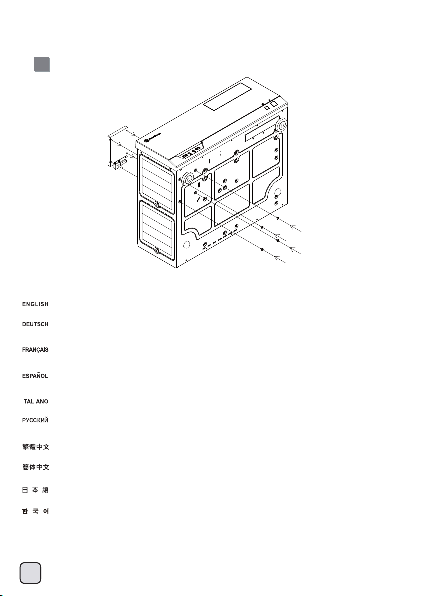
(2) Extra expansion slot
GD09 has an extra expansion slot for use with device or short expansion card such as extra motherboard I/O, fan controller, SilverStone’s
ClearCMOS, or daughter board (e.g. ASUS Xonar HDAV1.3), Please refer to the following illustration for installation.
Das GD09 hat einen zusätzlichen Erweiterungssteckplatz zur Nutzung mit Geräten oder kurzen Erweiterungskarten, wie einem zusätzlichen
Motherboard-I/O, einer Lüftersteuerung, SilverStones ClearCMOS oder einer Tochterkarte (z. B. ASUS Xonar HDAV1.3). Bitte beachten Sie
zur Installation die nachstehende Abbildung.
Le GD09 dispose d'un fente d'extension supplémentaire pour l'utilisation avec un périphérique ou une courte carte d'extension tels qu'une
carte mère E/S supplémentaire, un contrôleur de ventilateur, SilverStone ClearCMOS ou une carte fille (par exemple ASUS Xonar HDAV1.3),
veuillez vous référer à l'illustration suivante pour l'installation.
La GD09 posee un zócalo de expansión extra para usarlo con dispositivos o tarjetas de expansión cortas como E/S extra de la placa base,
controlador de ventiladores, ClearCMOS de SilverStone o una placa hija (como la ASUS Sonar HDAV 1.3). Por favor, consulte la siguiente
ilustración para la instalación.
GD09 ha uno alloggio di espansione aggiuntivo per l'utilizzo con dispositivi o schede di espansione corte come I/O scheda madre, controller
ventola, ClearCMOS di SilverStone o scheda figlia (ASUS Xonar HDAV1.3, ad esempio). Fare riferimento ai seguenti scenari per l’installazione.
GD09 имеет дополнительный слот расширения для использования устройства или короткой карты расширения, например
дополнительной карты ввода-вывода системной платы, контроллера вентилятора, SilverStone ClearCMOS или дочерней платы
(например, ASUS Xonar HDAV1.3). При установке руководствуйтесь следующей иллюстрацией.
GD09에는 예비 메인보드 I/O, 팬 컨트롤러, SilverStone의 ClearCMOS 또는 도터 보드(예: ASUS Xonar HDAV1.3)와 같은 장치 또는
짧은 확장 카드와 사용할 수 있는 예비 확장 슬롯이 있습니다. 설치 시 다음 그림을 참조하십시오.
GD09 は拡張マザーボードI/O、ファンコントローラ、SilverStone製ClearCMOSまたはドーターボード(例:ASUS Xonar HDAV1.3)
のようなデバイスまたは短い拡張カード用としての余分の拡張スロットを備えています、インストールは下図をご参照ください。
GD09有多一個擴充槽提供ClearCMOS或是是ASUS Xonar HDAV1.3音效子卡這種裝置使用,要使用請參考下圖整個擴充槽蓋拆下來安裝即可。
GD09有多一个扩展槽提供ClearCMOS或是是ASUS Xonar HDAV1.3音效子卡这种装置使用,要使用请参考下图整个扩展槽盖拆下来安装即可。
29
Page 32

Upgrade and maintenance
(3) Multi-purpose drive cage design
Below illustrations shows corresponding mounting points for each drive slot:
1.
2.
3. 4. 5.
There is no installation order if a 5.25” device is installed on top of the optical drive cage with 3.5” drive installed underneath.
However, there are recommended orders when installing drive sizes smaller than original, please refer to the following table for more
information:
Es gibt keine Installationsreihenfolge, wenn ein 5,25-Zoll-Gerät im oberen Bereich des Käfigs für optische Laufwerke mit darunter
installiertem 3,5-Zoll-Laufwerk montiert wird.
Es gibt jedoch empfohlene Abfolgen, wenn kleinere Laufwerke installiert werden; bitte beachten Sie dazu die nachstehende Tabelle:
Il n'y a pas d'ordre d'installation si un périphérique 5,25" est installé au-dessus de la cage du lecteur optique avec un disque 3,5" installé
dessous. Cependant, il y a des ordres recommandés lors de l'installation de disques de tailles plus petites que l'original, veuillez vous
référer au tableau ci-dessous pour plus d'informations :
30
Page 33

Upgrade and maintenance
No hay orden de instalación si se instala un dispositivo de 5,25” sobre la carcasa para dispositivo óptico con un dispositivo
de 3,5” instalado debajo. Sin embargo, existe un orden recomendado cuando se instalan dispositivos con un tamaño más pequeño del
original, por favor consulte la tabla siguiente para más información:
Non c'è un ordine di installazione se un dispositivo 5,25" è installato sulla parte superiore del drive cage dell'unità ottica con unità ottica
da 3,5" unità installata sotto. Tuttavia, ci sono ordini consigliati durante l'installazione di unità di dimensioni inferiori rispetto all'originale;
fare riferimento alla tabella che segue per altre informazioni:
Порядка установки не существует, если сверху отсека оптического привода устанавливается 5,25-дюймовое устройство,
а снизу 3,5-дюймовый диск.
Однако, существует рекомендуемый порядок при установке дисков меньшего размера (см. следующую таблицу).
5.25” 장치가 광드라이브 케이지의 상단에, 3.5” 드라이브를 하단에 설치할 경우 설치 순서가 상관 없습니다.
그러나 크기가 원래보다 작은 드라이블 설치할 경우 권장 순서가 있습니다. 자세한 내용은 다음 표를 참조하십시오.
5.25”装置が、3.5”ドライブを下方に取り付けた光学ドライブケージ上部に設置される場合、その順序は問いません。
ただし、通常より小さいサイズのドライブを設置する際は推奨された順序があります。詳細は下表をご参照ください。
光碟架在安裝上層為5.25”,下層為3.5”時是沒有先後順序性,但是在所有向下相容安裝都有先後順序,請參考下表安裝
光盘架在安装上层为5.25”,下层为3.5”时是没有先后顺序性,但是在所有向下兼容安装都有先后顺序,请参考下表安装
Top
5.25”
3.5”
2X2.5”
Bottom
3.5” 2.5”
No order
Install top drive first
Install top drive first
Install bottom drive first
Install bottom drive first
Install top drive first
31
Page 34

Protect Your Computer
Kensington Security Slot
A lock and cable can be purchased on the market for use with the Kensington security slot located on rear of GD09 to prevent removal
of the entire computer or top cover.
Caution: Please check for compatibility before purchasing the lock and cable for use with GD09’s Kensington security slot.
Durch ein Kensington-Schloss am GD09 kann verhindert werden, dass das gesamte System oder die obere Abdeckung entfernt wird.
Achtung: Vergewissern Sie sich vor dem Kauf eines solchen Schlosses, dass es kompatibel mit dem Einbauplatz des
Kensington-Sicherheitssystems ist.
Un verrou Kensington peut être utilisé sur le GD09 pour éviter le retrait du système ou du couvercle supérieur.
Attention:avant d’acheter ce verrou, assurez-vous qu’il est compatible avec la fente de verrouillage Kensington de votre GD09.
Se puede usar un cierre Kensington con la GD09 para evitar mover todo el sistema o solo la cubierta superior.
Atención: antes de comprar el cierre, asegúrese de que es compatible con el cierre de seguridad Kensington de la GD09.
Su GD09 può essere usato un dispositivo di protezione Kensington per impedire la rimozione dell’intero il sistema o della copertura coperchio.
Attenzione: Prima di acquistare il lock, assicuratevi che sia compatibile con lo slot presente sul GD09.
Замок Kensington можно использовать с корпусом GD09 для предотвращения снятия всей системы или верхней крышки.
Внимание! Перед приобретением замка убедитесь, что он совместим с гнездом защиты Kensington на корпусе GD09.
GD09에 Kensington 잠금장치를 사용하여 전체 시스템 또는 상단 커버가 분리되는 것을 방지할 수 있습니다.
주의: 잠금장치를 구입하기 전, GD09의 Kensington 보안 슬롯과 호환되는지 확인해야 합니다.
GD09には、全システムまたはトップカバーの取り外しを防止するのにケンジントンロックが、使用できます。
注意:ロック購入時には、それがGD09のケンジントンセキュリティスロットと互換性を持つことを確認してください。
安全纜線鎖是從市面上可以買到的防盜裝置。若要使用該鎖,請將其連接至您的GD09上的安全纜線孔。可以避免整台電腦被搬走,
同時保護左右側板避免被開啟。
注意事項:購買防盜裝置之前,請確定它適用於您電腦上的安全纜線孔。
安全缆线锁是从市面上可以买到的防盗装置。若要使用该锁,请将其连接至您的GD09上的安全缆线孔。可以避免整台计算机被搬走,
同时保护左右侧板避免被开启。
注意事项:购买防盗装置之前,请确定它适用于您计算机上的安全缆线孔。
32
Page 35

Q&A
Q: I found that the GD09 is too large to fit in my home theater cabinet after installing the display output adapter. How can I solve this problem?
A: Please use the adapter cable as a replacement for the display output adaptor. The cable can be bent in any direction to ensure that the
GD09 fits comfortably inside your home theater cabinet.
Q: Das GD09 ist zu groß; nach der Installation des Anzeigeausgangsadapters passt es nicht mehr in meinen Heimkinoschrank.
Wie kann ich dieses Problem lösen?
A: Bitte verwenden Sie alternativ zum Anzeigeausgangsadapter das Adapterkabel. Das Kabel kann beliebig ausgerichtet werden; auf diese
Weise können Sie das GD09 bequem in Ihrem Heimkinoschrank unterbringen.
Q: J’ai trouvé que le GD09 est trop grand pour tenir sur mon meuble Hi-fi après avoir installé l’adaptateur pour la sortie de l’affichage.
Comment puis-je résoudre ce problème?
R: Veuillez utiliser un câble adaptateur en guise de remplacement de l’adaptateur de type connecteur. Le câble peut être tordu dans tout les
sens et vous permettra ainsi de loger le GD09 confortablement dans votre meuble Hi-fi.
Q: Tras instalar el adaptador de salida de vídeo compruebo que la GD09 es demasiado grande para encajar dentro de mi mueble para cine
en casa. ¿Cómo puedo resolver este problema?
R: Por favor, use el cable adaptador como sustituto del adaptador de salida de vídeo. El cable puede doblarse en cualquier dirección para
asegurarse de que la GD09 encaja sin problemas dentro de su mueble para cine en casa.
Q:Trovo che il mio GD09 sia troppo largo per entrare nel mobile dopo aver installato l’adattatore VGA. Come posso risolvere
questo problema?
A: Utilizzare un cavo in luogo dell’adattatore. Il cavo può essere piegato in qualsiasi direzione assicurando quindi il posizionamento di
GD09 all’interno del vostro mobile per home theatre.
Q:После подсоединения выходного адаптера для дисплея корпус GD09 не помещается в мою стойку для домашнего кинотеатра.
Как решить эту проблему?
O: Используйте кабель-переходник вместо выходного адаптера для дисплея. Кабель можно изогнуть в любом направлении, чтобы
установить корпус GD09 в
Q: 디스플레이 어댑터 케이블을 장착한뒤 GD09이 홈시어터 캐비넷에 장착하기에 너무 큰것을 확인하였는데 어떻게 해결할 수 있을까요?
A: 디스플레이 어댑터 출력을 대체하기위해 어댑터 케이블을 사용하기 바랍니다. 케이블은 어떤 방향으로도 구부러질수 있어 GD09이
홈시어터 캐비넷에 잘 들어갈 수 있습니다.
Q: GD09にディスプレイ出力アダプタを設置すると、ホームシアターキャビネットに収まらなくなりました。 この問題をどのように解決
できるでしょうか?
A: アダプタケーブルをディスプレイ出力アダプタの代わりに使用します。ケーブルは任意の方向に曲がるので、ホームシアターキャビネ
ット内にGD09を正常に収めることができます。
Q: 我的電視櫃空間有限,嘗試著將GD09塞入,但是發現後端的螢幕訊號轉頭導致主機無法塞入,怎麼辦?
A: 請以轉接線替代。
стойке для домашнего кинотеатра.
Q: 我的电视柜空间有限,尝试着将GD09塞入,但是发现后端的屏幕讯号转头导致主机无法塞入,怎么办?
A: 请以转接线替代。
33
Page 36

Warranty information
This product has a limited 1 year warranty in North America and Australia.
For information on warranty periods in other regions, please contact your reseller or
SilverStone authorized distributor.
Warranty terms & conditions
1. Product component defects or damages resulted from defective production is covered under warranty.
Defects or damages with the following conditions will be fixed or replaced under SilverStone Technology’s jurisdiction.
a) Usage in accordance with instructions provided in this manual, with no misuse, overuse, or other inappropriate actions.
b) Damage not caused by natural disaster (thunder, fire, earthquake, flood, salt, wind, insect, animals, etc…)
c) Product is not disassembled, modified, or fixed. Components not disassembled or replaced.
d) Warranty mark/stickers are not removed or broken.
Loss or damages resulted from conditions other than ones listed above are not covered under warranty.
2. Under warranty, SilverStone Technology’s maximum liability is limited to the current market value for the product (depreciated value, excluding
shipping, handling, and other fees). SilverStone Technology is not responsible for other damages or loss associated with the use of product.
3. Under warranty, SilverStone Technology is obligated to repair or replace its defective products. Under no circumstances will SilverStone
Technology be liable for damages in connection with the sale, purchase, or use including but not limited to loss of data, loss of business, loss of
profits, loss of use of the product or incidental or consequential damage whether or not foreseeable and whether or not based on breach of warranty,
contract or negligence, even if SilverStone Technology has been advised of the possibility of such damages.
4. Warranty covers only the original purchaser through authorized SilverStone distributors and resellers and is not transferable to a second hand
purchaser.
5. You must provide sales receipt or invoice with clear indication of purchase date to determine warranty eligibility.
6. If a problem develops during the warranty period, please contact your retailer/reseller/SilverStone authorized distributors or SilverStone
http://www.silverstonetek.com.
Please note that: (i) You must provide proof of original purchase of the product by a dated itemized receipt; (ii) You shall bear the cost of shipping
(or otherwise transporting) the product to SilverStone authorized distributors. SilverStone authorized distributors will bear the cost of shipping
(or otherwise transporting) the product back to you after completing the warranty service; (iii) Before you send the product, you must be issued a
Return Merchandise Authorization (“RMA”) number from SilverStone. Updated warranty information will be posted on SilverStone’s official website.
Please visit http://www.silverstonetek.com for the latest updates.
Additional info & contacts
For North America (usasupport@silverstonetek.com)
SilverStone T echnology in North America may repair or replace defective product with refurbished product that is not new but has been functionally tested.
Replacement product will be warranted for remainder of the warranty period or thirty days, whichever is longer. All products should be sent
back to the place of purchase if it is within 30 days of purchase, after 30 days, customers need to initiate RMA procedure with SilverStone Technology
in USA by first downloading the “USA RMA form for end-users” form from the below link and follow its instructions.
http://silverstonetek.com/contactus.php
For Australia only (support@silverstonetek.com)
Our goods come with guarantees that cannot be excluded under the Australian Consumer Law.
You are entitled to a replacement or refund for a major failure and for compensation for any other reasonably foreseeable loss or damage.
You are also entitled to have the goods repaired or replaced if the goods fail to be of acceptable quality and the failure does not amount to a major failure.
Please refer to above “Warranty terms & conditions” for further warranty details.
SilverStone Technology Co., Ltd. 12F No. 168 Jiankang Rd., Zhonghe Dist., New Taipei City 235 Taiwan R.O.C. + 886-2-8228-1238
(standard international call charges apply)
For Europe (support.eu@silverstonetek.de)
For all other regions (support@silverstonetek.com)
NO: G11220810
 Loading...