

Page 1
January, 2013
GD06
NO: G11213051
Page 2
Installation and system optimization guide:
The following manual and guides were carefully prepared by the SilverStone engineering team to help
you maximize the potential of your SilverStone product. Please keep this manual for future reference
when upgrading or performing maintenance on your system. A copy of this manual can also be
downloaded from our website at:
http://www.silverstonetek.com
Specification
Disassemble chart
Installation guide
Connector definition
Front I/O connector guide
Component size limitations
Recommended cooling device setup & selection
Fan & fan filter disassembly guide
Dual purpose space
Expansion card removal guide
Protect your computer
Q&A
P.2
P.3
P.4
P.17
P.18
P.18
P.24
P.26
P.29
P.30
P.32
P.34
1
Page 3
GD06
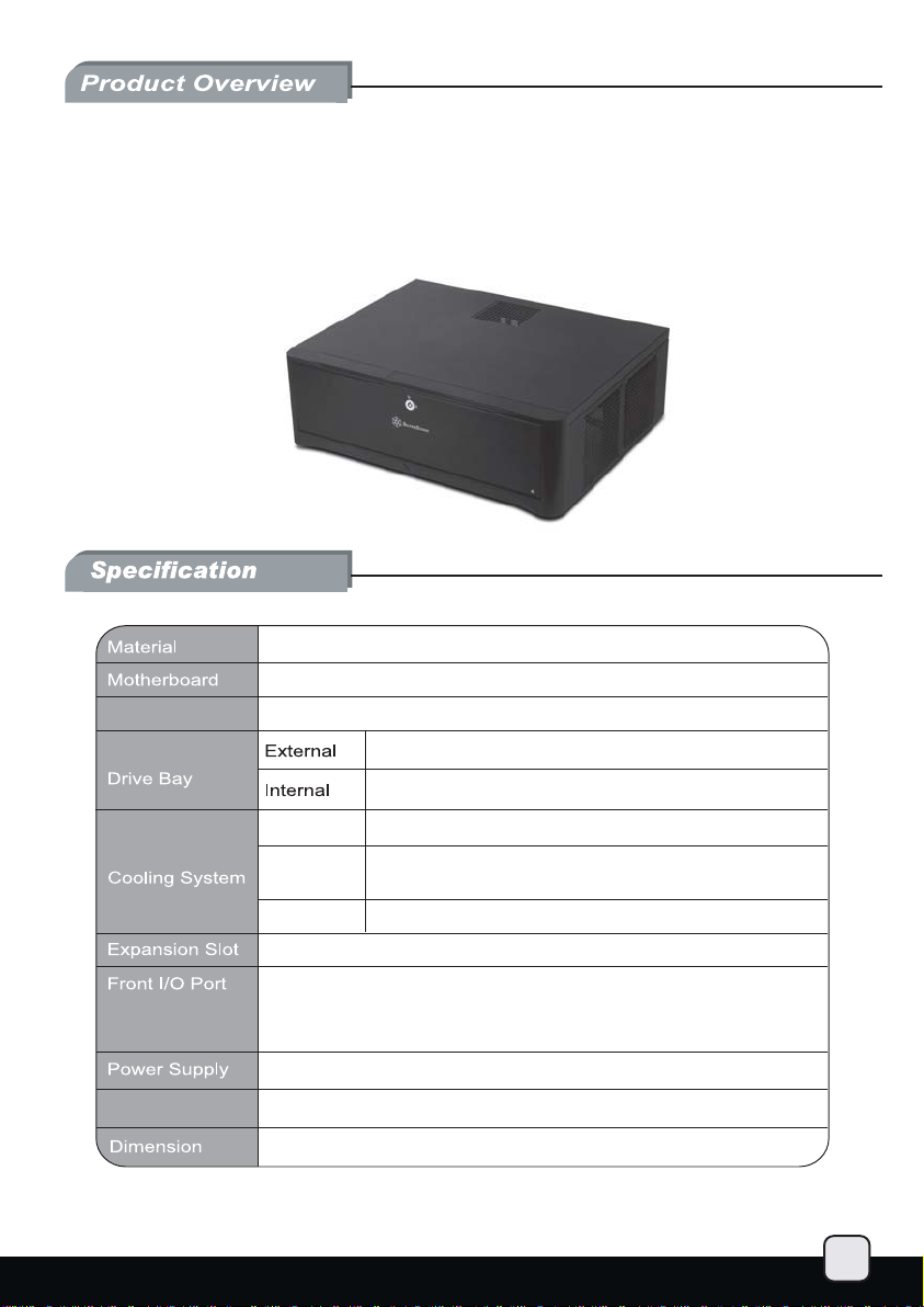
Stunning HTPC chassis with impressive cooling
and storage capability
Aluminum front door and plastic front panel, 0.8mm SECC body
Micro ATX, Mini-DTX, Mini-ITX
Model No.
SST-GD06B (Black)
5.25" x 1
3.5" x 4, 2.5” x 1 or 3.5" x 3, 2.5” x 2
Right Side
Left Side
Rear
USB 3.0 x 2
audio x 1
MIC x 1
Support standard PS2 (ATX) up to 150mm
2 x 120mm intake fans, 1200rpm, 20dBA
1 x 120mm intake fan, 1200rpm, 20dBA
(Also compatible with 80mm fan)
2 x 80mm fan slots (optional mounting)
5
Expansion Card
Support graphic cards up to 11 inches
440 mm (W) x 150 mm (H) x 340 mm (D)
2
Page 4
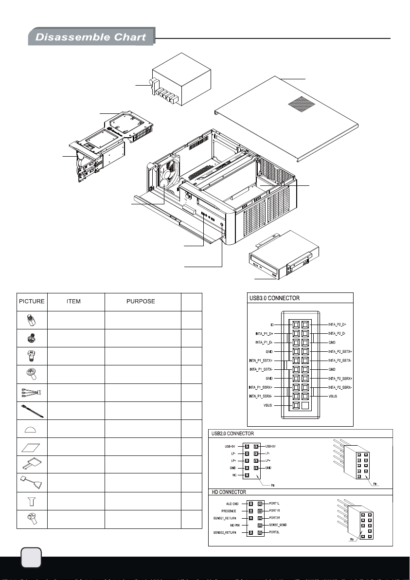
3.5” or 2.5” DRIVE
BRACKET
3.5” HOT SWAP
DRIVE BRACKET x 2
PS2 / ATX PSU (OPTION)
12025 FAN
USB3.0 x 2 + SPK + MIC
RESET BUTTON
5.25” DRIVE BRACKET
QTY
TOP COVER
MICRO ATX M/B
(OPTION)
3
METAL SPACER
SCW-HW-6-32
SCW-HDD-6-32
SCW-PW-M3
FAN CABLE
BUNCH WIRE TIES
PSU RUBBER
MANUAL
KEY
USB ADAPTER
SCW-TF-M3
SCW-TF-6-32
SECURE MOTHERBOARD
SUCURE POWER SUPPLY OR
PSU PKT AND MOTHERBOARD
SECURE 3.5"HARD DRIVE
SECURE 2.5" DRIVE
LINK FANS TO POWER SUPPLY
SECURE WIRE
REDUCE PSU VIBRATION
INSTALLATION GUIDE
LOCK FRONT DOOR
USB3.0 TO USB2.0
COVERTOR CABLE
SECURE OPTICAL DRIVE
SECURE 3.5” HARD DRIVE
IN 5.25” DRIVE BRACKET
2
13
4
8
1
5
4
1
2
1
4
4
Page 5
lnstallation Guide
Before you begin, please make sure that you.
(1) have all components collected.
(2) check that all components do not have compatibility problems with each other or with the case.
(3) if possible, assemble the components outside the case first to make sure they are working.
(4) keep the motherboard manual ready for reference during installation.
(5) prepare a Philips screwdriver.
1
1
2
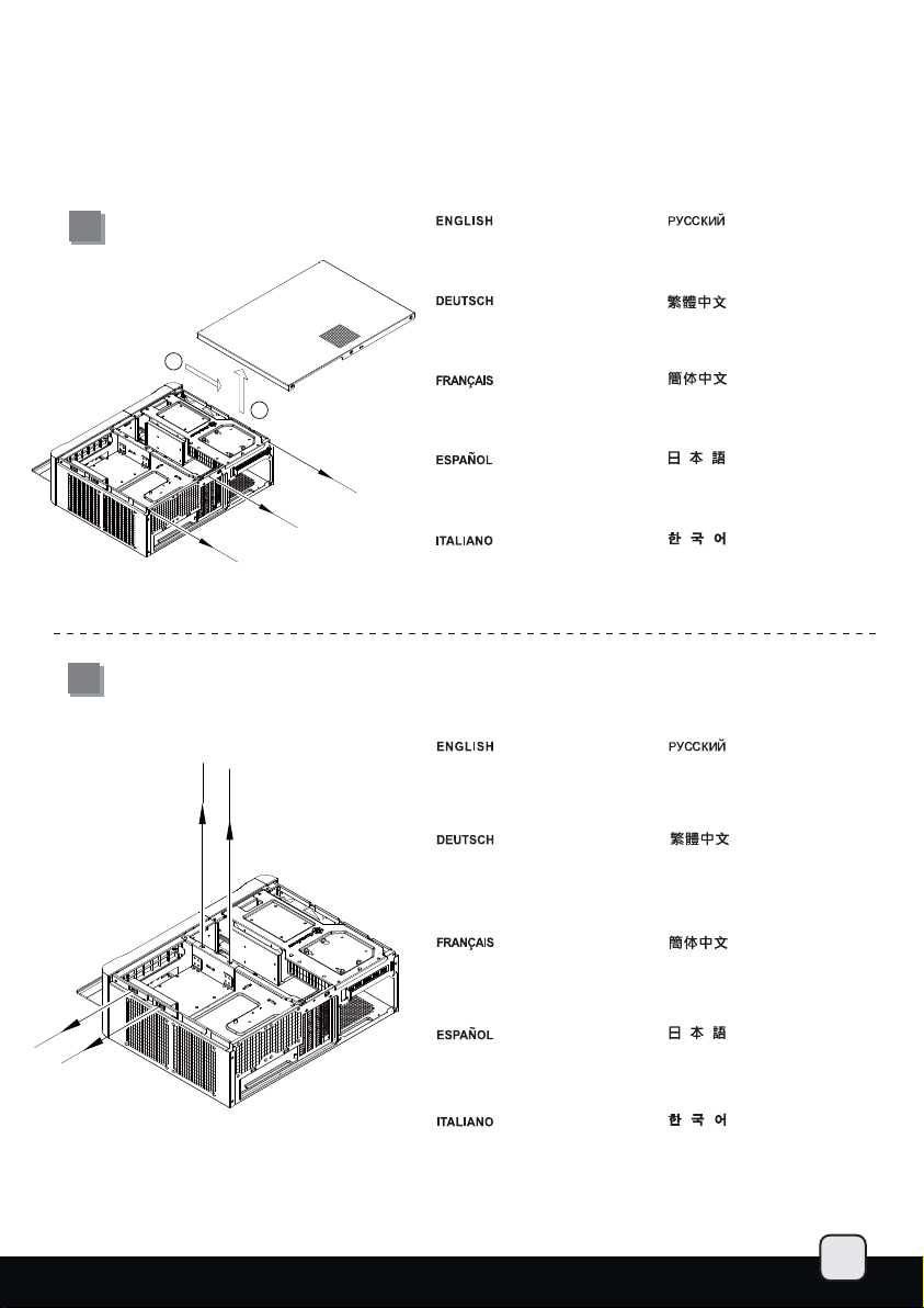
Unscrew the three screws from the
rear of the chassis then remove the
top cover.
Lösen Sie die drei Schrauben an der
Rückseite des Gehäuses, nehmen
Sie dann die obere Abdeckung ab.
Dévissez les trois vis de l'arrière
du boîtier puis retirez le panneau
supérieur.
Desatornille los tres tornillos de la
parte posterior del chasis y luego
retire la cubierta superior.
Svitare le 3 viti poste sul retro dello
chassis quindi rimuovere il cover
superiore.
Открутите три шурупа с задней
части корпуса, затем снимите
верхнюю крышку.
先用螺絲起子鬆開三顆螺絲,
再取下上蓋板。
先用螺丝起子松开三颗螺丝,
再取下上盖板。
ケース後部からネジ3本を外し、
カバーを取り外します。
케이스 후방의 3개의 나사를 풀고
상부 커버를 제거합니다.
2
Unscrew four screws holding the
optical drive bracket to remove it.
Lösen Sie die vier Schrauben, welche
den Schacht für das optische Laufwerk
halten, nehmen Sie den Schacht heraus.
Открутите четыре шурупа,
удерживающих кронштейн
жесткого диска, и выньте
кронштейн.
鬆開光碟架4顆螺絲,卸下光碟架。
Dévissez les quatre vis fixant le
casier du lecteur optique afin de
le retirer.
Desatornille cuatro tornillos que
sujetan el bracket del dispositivo
óptico y luego retírelo.
Svitare le 4 viti che tengono la staffa
del drive ottico e quindi rimuoverlo.
松开光盘架4颗螺丝,卸下光盘架。
光学ドライブブラケットを固定してい
るネジ4本を外し、ブラケットを取り
外します。
광드라이브 브라켓을 고정하고 있는
4개의 나사를 제거합니다.
4
Page 6
lnstallation Guide
3
4
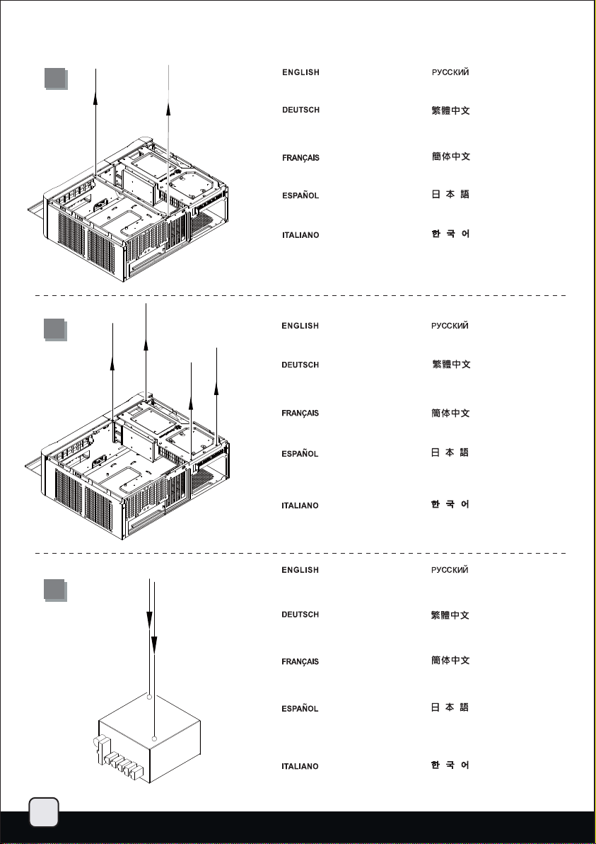
Unscrew two screws from the
center brace to remove it.
Lesen Sie die beiden Schrauben an
der mittleren Halterung, nehmen Sie
die Halterung heraus.
Dévissez les deux vis de la barre
centrale afin de la retirer.
Desatornille dos tornillos del eje
central para quitarlo.
Svitare le due viti del gancio
centrale per rimuoverlo.
Remove the screws from the hard
drive bracket to remove it.
Lösen Sie die Schrauben an der
Festplattenhalterung, nehmen Sie
auch diese Halterung heraus.
Retirez les vis du casier à disque
dur pour le démonter.
Quite los tornillos del bracket para
discos duros para retirarlo.
Открутите два шурупа на
центральной скобе и выньте ее.
鬆開中支架2顆螺絲,卸下中支架。
松开中支架2颗螺丝,卸下中支架。
中央の支柱のネジ2本を外して、
取り外します。
중앙 버팀대의 2개의 나사를
제거합니다.
Удалите винты из кронштейна для
жестких дисков, чтобы снять его.
鬆開鎖固硬碟架的螺絲,
把硬碟架取下。
松开锁固硬盘架的螺丝,
把硬盘架取下。
ハードドライブブラケットから
ネジを外してブラケットを取り
外します。
Svitare le viti dal supporto degli
hard disk situato in per rimuoverlo.
Adhere the included power supply
5
feet to the end of the power supply
for support.
Bringen Sie die mitgelieferten
Netzteilfüße am Ende des
Netzteils an.
Collez les pieds fournis à l'arrière
de votre alimentation pour la
supporter.
Pegue los pies incluidos para la
fuente de alimentación en la parte
posterior de la fuente de alimentación
como apoyo.
Attaccare i piedini adesivi dell’
alimentatore alla fine dello stesso
per assicurarne il supporto.
하드 드라이브 브라켓의 나사를
풀어 제거합니다.
Прикрепите прилагаемые опорные
ножки к блоку питания.
在電源供應器末端兩端黏貼電源供應器
腳墊以支撐電源供應器。
在电源供应器末端两端黏贴电源供应器
脚垫以支撑电源供应器。
付属の電源フットを、電源を固定する
ため取り付けます。
동봉된 파워 서플라이 서포터를 끝에
잘 맞추어 고정 및 지지 시킵니다.
5
Page 7
lnstallation Guide
6
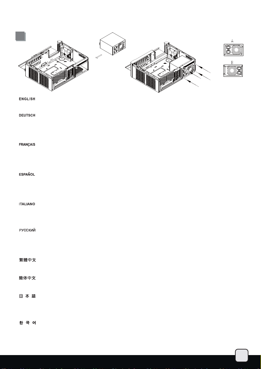
Install power supply into the case. Please note the case supports mounting power supply in two different orientations.
(For more information regarding power supply size limitations, please refer to the component guide in later pages).
Installieren Sie das Netzteil im Gehäuse. Bitte beachten Sie, dass das Gehäuse die Montage des Netzteils in zwei verschiedenen
Ausrichtungen unterstützt. Wenn Sie ein Netzteil mit 80 mm-Lüfter nutzen, können Sie die Ausrichtung wie gewünscht zur
Vereinfachung der Kabelverwaltung anpassen. Wenn Sie ein Netzteil mit einem 120 mm- oder größeren Lüfter nutzen, muss der
Lüfter bei der Installation nach unten gerichtet sein. (Weitere Informationen zur Beschränkung der Netzteilgröße entnehmen Sie
bitte der Komponentenanleitung weiter hinten).
Installez l'alimentation dans le boîtier. Veuillez noter que le boîtier permet le montage des alimentations dans les deux sens. Si
vous utilisez une alimentation avec un ventilateur de 80mm, vous pouvez librement choisir le sens selon la facilité de câblage
que cela vous accordera. Si vous utilisez une alimentation avec un ventilateur de 120mm ou plus, vous devez l'installez avec le
ventilateur vers le bas. (Pour plus d'informations sur les limitations des tailles des alimentations, veuillez-vous référer au guide
des composant dans les pages à venir).
Instale la fuente de alimentación en la carcasa. Por favor, tenga en cuenta que la carcasa monta la fuentes de alimentación
orientada de dos modos distintos. Si usa una fuente de alimentación con un ventilador de 80mm, puede escoger la orientación
que prefiera para así ordenar mejor los cables. Si usa una fuente de alimentación con un ventilador de 120mm ó mayor, debe
hacerlo con el ventilador hacia abajo. (Para más información sobre las limitaciones de tamaño de la fuente de alimentación,
consulte por favor la guía de componentes en páginas posteriores).
Installare l’alimentatore nel case. L’alimentatore può essere orientato in due modi differenti. Se state installando un alimentatore con
\ventola da 80mm, potete scegliere liberamente entrambe le posizioni optando per quella che meglio favorisce una facile sistemazione
dei cavi. Se invece utilizzate un alimentatore con ventola da 120mm o più grande, dovete installarlo con la ventola rivolta verso il basso
(per maggiori informazioni in merito alle limitazioni di misura degli alimentatori, fate riferimento a quanto esposto nelle pagine successive).
Установите источник питания в корпус. Обратите внимание, что можно установить источник питания в двух разных направлениях.
При использовании источника питания с вентилятором 80 мм можно использовать любое направление для упрощения расположения
кабелей. При использовании источника питания с вентилятором
вентилятор был направлен вниз. (для получения дополнительной информации относительно ограничений размера источников
питания см. руководство к компонентам далее).
安裝電源供應器,請注意此機殼的正反裝設計,是為了讓你使用80mm風扇電源時,選擇性調整電源出線的位置,如果使用120mm風扇電源,
請一定要將風扇朝下,以免風扇吸不到風(關於電源供應器長度規格,請參考元件尺寸限制)
安装电源供应器,请注意此机壳的正反装设计,是为了让你使用80mm风扇电源时,选择性调整电源出线的位置,如果使用120mm风扇电源,
请一定要将风扇朝下,以免风扇吸不到风(关于电源供应器长度规格,请参考组件尺寸限制)
ケースに電源をインストールします。ケースは2つの異なる方向での電源設置をサポートしていることにご注意ください。80mmファン
装備の電源を使う場合、必要に応じてケーブルを容易に取り回せる向きを自由に選ぶことができます。120mmファンまたはより大型フ
ァン装備の電源を使う場合、ファンを下向きに設置します。(電源サイズ制限の詳細については、後のページに記載のコンポーネント
ガイドをご参照ください。)
파워 서플라이를 케이스에 설치합니다. 이 케이스는 파워 서플라이를 두개의 방향을 설치 가능합니다. 만약 파워 서플라이가 80mm팬을
사용한다면, 케이블 정리가 손쉬운 쪽을 선택해 설치 바랍니다. 만약 120mm 혹은 그 이상의 팬을 사용하는 파워 서플라이를 사용할 경우,
팬이 아래쪽을 향하도록 설치하면 됩니다. (만약 파워 서플라이의 크기 및 제한에 대한 자세한 정보를 확인하려면, 뒤에 나오는 부품
가이드를 참조 바랍니다. ).
120 мм или более следует устанавливать его таким образом, чтобы
6
Page 8
lnstallation Guide
7
8
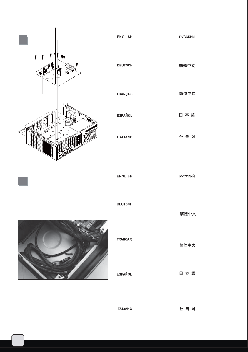
Insert the I/O shield included with
your motherboard, then install the
motherboard into the case.
Setzen Sie das mit Ihrem Motherboard
gelieferte I/O-Blech in die Aussparungen
an der Rückseite des Gehäuses ein,
installieren Sie anschließend das
Motherboard im Gehäuse.
Insérez la plaque d'E/S inclus avec
votre carte mère, puis installez la
carte mère dans le boîtier.
Inserte el protector de E/S incluido
en su placa base, luego instale la
placa base en la carcasa.
Installare la mascherina I/O inclusa
con la scheda madre, quindi installare
la mainboard nel case.
We recommend at this point to start thinking
about routing the cables cleanly before
connecting them to the motherboard, cables
include fan cables, power supply 24pin cable,
CPU ATX 4pin/EPS12V 8pin, front panel
connectors, and front I/O connectors.
An diesem Punkt empfehlen wir Ihnen, über
eine saubere Verlegung der Kabel
nachzudenken, bevor Sie die Kabel an das
Motherboard anschließen. Zu den Kabeln
zählen Stromversorgungskabel (24-polig),
CPU ATX-Kabel (4-polig)/EPS 12 V-Kabel
(8-polig), Frontblenden-Anschlusskabel sowie
Front-I/O-Kabel.
A ce stade nous recommandons de
commencer à organiser proprement les
câbles avant de les brancher à la carte
mère, câbles de ventilateurs, connecteur
24pin de l'alimentation, Connecteur ATX 4
pin/EPS12V 8pin du processeur,
connecteurs du panneau frontal, et les
connecteurs des ports E/S frontaux.
8Le recomendamos que en este punto
comience a enrutar los cables con limpieza
antes de conectarlos a la placa base. El
término “cables” incluye los cables de los
ventiladores, el cable de 24 pines de la
fuente de alimentación, el de 4 pines CPU
ATX/8 pines EPS12V, conectores del panel
frontal y conectores de E/S frontales.
A questo punto, si raccomanda di pensare a
come gestire la disposizione dei cavi interni
prima di connetterli alla scheda madre. Si fa
riferimento ai i cavi delle ventole, all cavo
dell’alimentatore a 24 pin, al 4pin ATX ed
EPS 12V 8 pin, alle connessioni del pannello
frontale ed alle connessioni frontali I/O.
Установите заглушку для разъёмов
задней панели материнской платы,
прилагаемую к материнской плате,
затем установите материнскую плату
в корпус.
塞入I/O彈片,裝入主機板。
塞入I/O弹片,装入主机板。
お持ちのマザーボードに付属のI/Oシ
ールドを挿入してから、ケースの中
にマザーボードを取り付けます。
메인보드와 같이 동봉된 I/O Shield를
삽입한 후, 메인보드를 케이스에
설치합니다.
Мы рекомендуем задуматься о прокладке
кабелей до их подключения к материнской
плате. Имеются в виду следующие кабели:
кабели вентиляторов, 24-контактный силовой
кабель, 4-контактный ATX и 8-контактный EPS
12В кабели ЦП, разъемы передней панели и
передние разъемы ввода/вывода.
我們建議你在這時就開始準備整線動作,
請將風扇電源線,
ATX 4Pin/EPS 8Pin
Connectors
機板。
我们建议你在这时就开始准备整线动作,
请将风扇电源线,
ATX 4Pin/EPS 8Pin
Connectors
机板。
マザーボードにケーブルを接続する前
に、すっきりしたケーブルの取り回し
を考え始めるようお勧めします。これ
には、ファンケーブル、電源
ーブル、CPU ATX 4ピン/EPS12V 8ピン、
フロントパネルコネクタ、およびフロ
ント
I/Oコネクタが含まれます。
이번 단계에서부터 케이블 정리에
대해 생각해 주시기를 권장합니다.
팬케이블, 파워 서플라이 24핀
케이블,
전면패널 커넥터, 전면 IO 커넥터
등이 대상이 됩니다.
PSU 24Pin接線, CPU
接線, Front Panel
與Front I/O Connectors,插上主
PSU 24Pin接线, CPU
接线, Front Panel
与Front I/O Connectors,插上主
24ピンケ
CPU, ATX 4핀/EPS 12V 8pin,
7
Page 9
lnstallation Guide
9
10
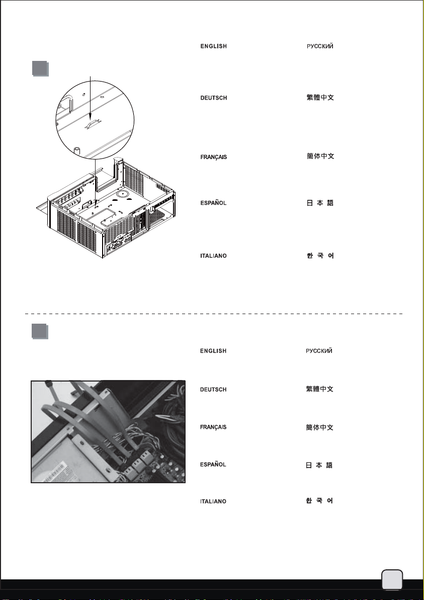
The tray areas around the motherboard
have many small pass-through holes
that can be used with included wire
tie, please refer to the illustration for
more information.
In den Bereichen rund um das
Motherboard finden Sie eine Reihe
kleiner Durchführungsöffnungen,
die Sie in Kombination mit dem
mitgelieferten Kabelbinder nutzen
können – schauen Sie sich dazu
bitte die Abbildung an.
La zone du support autour de la carte
mère possède plusieurs petits trous
pour faire passer des câbles, veuillezvous référer aux illustrations pour plus
d'information.
Las zonas de las bandejas alrededor
de la placa base tienen muchos
agujeros pequeños que pueden ser
usados con las bridas incluidas, por
favor consulte la ilustración para
tener más información.
L’area circostante la scheda madre
possiede diversi fori che possono
essere utilizzati per il passaggio dei
cavi, utilizzando anche le fascette
in dotazione. Fare riferimento
all’illustrazione per maggiori dettagli.
Вокруг материнской платы предусмотрено
большое количество маленьких сквозных
отверстий, которые можно использовать
для прилагаемых стяжек для кабелей, см.
рисунок.
主機板週邊備有許多功綁線用的凸橋,
可配合零件包所附的束線帶使用,請
參考上圖使用。
主机板外围备有许多功绑线用的凸桥,
可配合零件包所附的束线带使用,
请参考上图使用。
マザーボード周辺のトレーエリアは、
付属のケーブルストラップに使用で
きる多くの小さなケーブル通し穴が
開いています。詳細については図を
ご参照ください。
메인보드 주변의 트레이에는 여러개의
작은 구멍이 있는데, 이를 이용해
동봉된 타이를 고정시킬 수 있습니다.
보다 자세한 정보는 그림을 참조해
주세요.
Please connect all the SATA (or IDE)
cables to the motherboard as required
by your system.
Bitte schließen Sie sämtliche für Ihr
System benötigten SATA- (oder IDE-)
Kabel an das Motherboard an.
Veuillez brancher tous les câbles
SATA (ou IDE) à la carte mère selon
les besoins de votre système.
Por favor, conecte todos los cables
SATA (ó IDE) a la placa base según
precise su sistema.
Connettere tutti i cavi SATA (o IDE)
alla scheda madre secondo le
esigenze del vostro sistema.
Подключите к материнской плате
все необходимые кабели SATA
(или IDE).
此時請數清楚您所需要的ATA排線數量
(通常是SATA),插上主機板。
此时请数清楚您所需要的ATA排线数量
(通常是SATA),插上主机板。
システムの必要に応じて、SATA
(またはIDE)ケーブル全部をマザ
ーボードに接続します。
필요한 모든 SATA 혹은 IDE
케이블을 메인보드에 연결합니다.
8
Page 10
lnstallation Guide
11
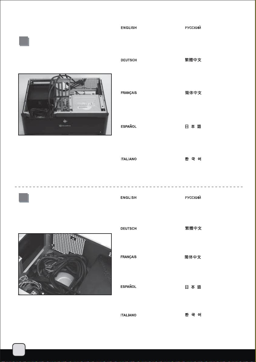
Now carefully count and separate the
required power cables for your hard
drive, optical drive, and graphics card.
Place the needed cables out of the case
and neatly place the unneeded power
cables into available space inside the
case.
Теперь аккуратно пересчитайте и
отделите друг от друга силовые кабели
для жесткого диска, оптического диска
и графической карты. Нужные кабели
вытащите из корпуса, а ненужные силовые
кабели аккуратно разместите внутри корпуса.
12
Zählen Sie nun die für Festplatte, optisches
Laufwerk und Grafikkarte erforderlichen
Kabel, trennen Sie diese. Führen Sie die
benötigten Kabel aus dem Gehäuse
heraus, platzieren Sie die nicht benötigten
Kabel an einer freien Stelle innerhalb des
Gehäuses.
Maintenant compter avec attention et séparez
les câbles d'alimentation requis pour vos
disques durs, lecteur optique, et cartes
graphiques. Placez les câbles nécessaires en
dehors du boîtier et regrouper habilement les
câbles non utilisé pour les loger dans l'espace
disponible dans le boîtier.
Ahora cuente con cuidado y separe los
cables de potencia necesarios para su
disco duro, dispositivo óptico y tarjeta
gráfica. Sitúe los cables necesarios por
fuera de la carcasa y coloque con cuidado
los que no necesite en el espacio que
quede dentro de la carcasa.
A questo punto contate e separate i cavi
di alimentazione che vi sono necessari,
quindi disponete quelli di cui non avete
bisogno in una parte del case che ritenete
opportuna.
The available free space in front of
the motherboard and power supply
has plenty of room for any excess
cables to be stored and tied down
using the included wire ties.
Vor Motherboard und Netzteil
finden Sie reichlich Platz, um
überschüssige Kabel abzulegen
und mit den mitgelieferten
Kabelbindern zu befestigen.
此時請數清楚您所需要的硬碟/光碟所需
電源線,以及顯示卡所需要的電源線,將需
要的線往外拉出機殼,並將不需要的電源
線整理繫好。
此时请数清楚您所需要的硬盘/光盘所需
电源线,以及显示卡所需要的电源线,将需
要的线往外拉出机壳,并将不需要的电源
线整理系好。
ハードドライブ、光学ドライブ、および
グラフィックカードのために必要とされ
る電源ケーブルを数え、取り分けます。
ケースから必要なケーブルを確認し、ケ
ースの中で利用可能な空間に不要な電源
ケーブルをきちんと整理してください。
그후, 하드 디스크, 광드라이브 그래픽
카드에 필요한 파워 케이블의 숫자를
확인하고 분리합니다. 필요한 케이블만
케이스 밖으로 내보낸 후, 나머지 케이블은,
케이스의 남은 공간에 가지런히 놓습니다.
Свободного места перед материнской
платой и блоком питания вполне
достаточно для размещения
неиспользуемых кабелей и скрепления
их прилагаемыми стяжками.
主機板,與電源供應器前端有相當大的
位置供放置多於線材用,請將線材放入,
必要時以束線帶固定。
L'espace libre disponible à l'avant de
la carte mère et de l'alimentation peut
être utilisé pour stocker les câbles
supplémentaires en les groupant
avec les fixations disponibles.
El espacio libre disponible en frente
de la placa base y la fuente de
alimentación es más que suficiente
para guardar y atar cualquier cable
que sobre usando las bridas.
Frontalmente alla scheda madre
ed all’alimentatore vi sono numerosi
spazi a disposizione per riporre i cavi
in eccesso, che possono essere uniti
utilizzando le fascette in dotazione.
主机板,与电源供应器前端有相当大的
位置供放置多于线材用,请将线材放入,
必要时以束线带固定。
マザーボードと電源の前には、ケーブ
ルやリード線を取り回したり結束した
りするのに使用できる十分なスペース
があります。
메인보드와 파워 서플라이 전면에는
여분의 케이블을 타이로 정리해 보관할
수 있는 충분한 공간이 마련되어
있습니다.
9
Page 11
lnstallation Guide
13
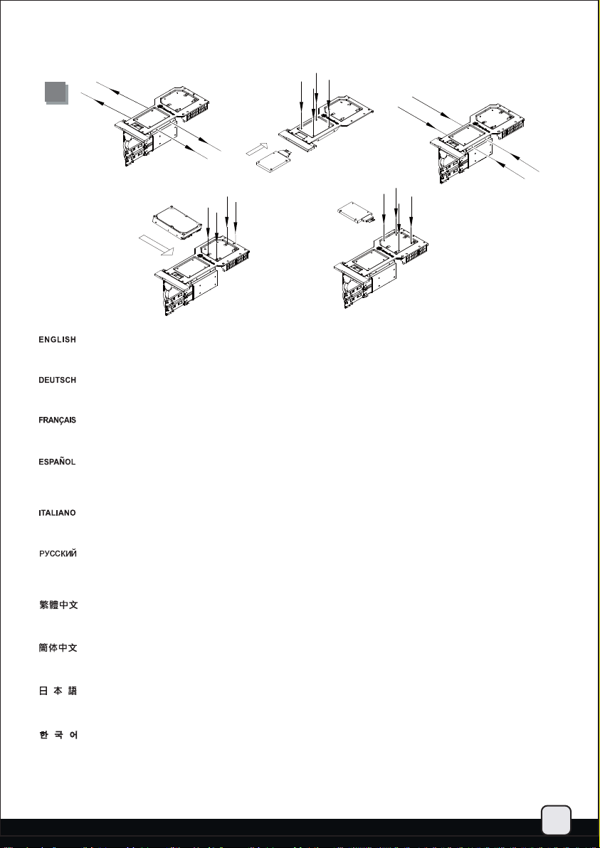
Install and secure any 3.5” or 2.5” hard drive into the hard drive bracket with screws. The purpose of using screws for hard drive
installation is to ensure complete isolation of hard drive from the bracket to maximize the vibration dampening pad’s effectiveness.
Installieren und fixieren Sie 3,5- oder 2,5-Zoll-Festplatten mit Schrauben in der Festplattenhalterung. Die Verwendung von Schrauben
zur Befestigung der Festplatten sorgt dafür, dass die Festplatten von der Halterung isoliert und Vibrationen effektiv gedämpft werden.
Installez et fixez tous les disques durs 3.5” ou 2.5” dans leur casier avec des vis. L'objectif d'utiliser des vis pour l'installation de disque durs
est d'assurer une isolation complète des disques durs à partir du casier pour maximiser l'efficacité des pads anti vibrations de celui-ci.
Instale y fije cualquier disco duro de 3,5” ó 2,5” en el bracket para discos duros usando tornillos. El propósito de usar tornillos para la
instalación del disco duro es asegurar un aislamiento completo del disco duro del bracket para maximizar la efectividad anti vibración
de la almohadilla.
Installare ed assicurare per mezzo delle opportune viti gli hard disk da 2,5” o 3,5” in vostro possesso, alla rispettiva staffa. L’utilizzo
delle viti assicura un completo isolamento del hard disk dalla staffa per massimizzare l’effetto dei pad antivibrazione.
Вставьте в кронштейн для жесткого диска 3,5-дюймовый или 2,5-дюймовый диск и закрепите его шурупами. Использование
шурупов при установке жесткого диска обеспечивает полную изоляцию диска от кронштейна, увеличивая эффективность
антивибрационных подкладок.
將3.5”硬碟與2.5”硬碟裝入上硬碟架,並鎖固螺絲,如果覺得螺絲不好定位,請不要怕麻煩,這是我們為了讓硬碟與硬碟架保持完全不接觸,
以發揮防震墊圈的最大效果。
将3.5”硬盘与2.5”硬盘装入上硬盘架,并锁固螺丝,如果觉得螺丝不好定位,请不要怕麻烦,这是我们为了让硬盘与硬盘架保持完全不接触,
以发挥防震垫圈的最大效果。
ハードドライブブラケットの中に3.5インチまたは2.5インチのハードドライブをインストールし、ネジで固定します。ハードドライブイン
ストールにネジを使う目的は、防振パッドの効果を最大にするために確実にブラケットからハードドライブが独立するようにすることです。
필요한 3.5” 혹은 2.5” 하드 드라이브를 하드 드라이브 브라켓에 설치한 후 나사로 고정시킵니다. 하드 드라이브 설치시 나사로 고정시키는
이유는 하드 드라이브를 브라켓으로 부터 완전히 분리시켜 진동 패드의 효과를 극대화 하기 위함입니다.
10
Page 12
lnstallation Guide
14
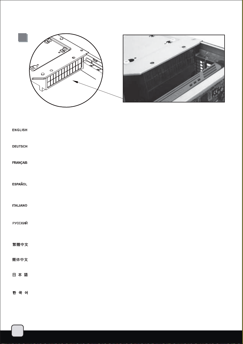
There is a rubber partition plate in the rear part of the hard drive bracket designed for channeling airflow to the top panel vents.
This plate has small flaps that can be removed if needed to create additional room for cables.
Im hinteren Teil der Festplattenhalterung finden Sie außerdem eine Gummiplatte, die den Luftstrom zu den Öffnungen an der Oberseite regelt.
Diese Platte verfügt über kleine Stege, die Sie entfernen können, falls Sie zusätzlichen Platz für Kabel benötigen sollten.
Il y a aussi une plaque de séparation en caoutchouc dans la partie arrière du casier à disques durs conçu pour diffuser les flux d'air vers les
aérations du panneau supérieur. Cette plaque possède des petits volets qui peuvent être retirés si vous avez besoin d'espace supplémentaire
pour y loger des câbles.
También hay una plancha de división de goma en la parte trasera del bracket del disco duro diseñada para canalizar el flujo de aire hacia
las aberturas del panel superior. Esta plancha tiene pequeñas solapas que pueden retirarse si es necesario para crear espacio adicional
para los cables.
Nella parte posteriore della staffa è presente anche un divisorio in gomma disegnato per convogliare il flusso d’aria verso le ventole poste sul
pannello superiore, lo stesso è dotato di flap che possono essere rimossi per creare ulteriore spazio per i cavi.
На задней части кронштейна жесткого диска находится резиновая разделительная перегородка, которая направляет поток воздуха к
вентиляционным отверстиям верхней панели. У этой перегородки есть маленькие щитки, которые можно снять и тем самым освободить
дополнительное место для кабелей.
後側硬碟架上有橡膠檔片是為了顯示卡的排風而設計的檔風罩.上面有破孔,有需要裝設硬碟排線與電源線時,可以適度撕除部分的檔片。
后侧硬盘架上有橡胶文件片是为了显示卡的排风而设计的档风罩.上面有破孔,有需要装设硬盘排线与电源线时,可以适度撕除部分的档片。
また、ハードドライブブラケットの後部には、気流を上部通気口に運ぶために設計されたゴム製仕切り板があります。この板には、ケーブル
用の余分のスペースを用意する必要がある場合に取り外せる小さなフラップが付いています。
하드 드라이브 브라켓의 후방에는 고무 파티션 판이 있어 상부 패널의 배기구로 공기의 흐름을 유도하기 위해 마련되어 있습니다. 이 판에는
작은 날개가 있어 케이블을 위해 보다 많은 공간이 필요하다면 제거도 가능합니다.
11
Page 13

lnstallation Guide
15
16
Reinstall the hard drive bracket,
connect the cables, and secure
with screws.
Bringen Sie die Festplattenhalterung
wieder an; verbinden Sie die Kabel
und ziehen Sie die Schrauben fest.
Réinstallez le casier à disque,
branchez les câbles, et fixez-le
avec des vis.
Reinstale el bracket para discos
duros, conecte los cables y fíjelo
con tornillos.
Reinstallare il support hard disk,
connettere I cavi ed assicurarlo
alla struttura con le viti.
Install and secure 3.5”hard drive
into the hard drive bracket with
screws. If the first PCI-E slot was
occupied, please use the 90 degree
SATA and power cables.
Установите кронштейн для
жестких дисков в корпус,
подключите кабели и закрепите
его винтами.
將硬碟架塞入機殼,連接好所需要
的接線後,再將螺絲鎖上。
将硬盘架塞入机壳,连接好所需要
的接线后,再将螺丝锁上。
ハードドライブブラケットを戻し、
ケーブルを接続してネジで固定し
ます。
하드 드라이브를 재장착하고,
케이블을 모두 연결한뒤, 나사로
고정합니다.
Установите в кронштейн для жестких
дисков и закрепите винтами 3,5дюймовый жесткий диск. Если занят
первый слот PCI-E, используйте
кабели SATA и кабели питания с
угловыми разъемами (90 градусов).
Installieren und befestigen Sie eine
3,5 Zoll-Festplatte mit Schrauben in
der Festplattenhalterung. Falls der
erste PCIe-Steckplatz belegt ist,
nutzen Sie bitte die um 90 Grad
abgewinkelten SATA- und Netzkabel.
Installez et fixez les disques durs 3.5”
dans els casiers avec des vis. Si le
premier emplacement d’extension
PCI-E est utilisé, veuillez utiliser un
connecteur SATA et un câble
d’alimentation orienté à 90 degrés.
Instale y fije el disco duro de 3,5”
en el bracket para discos duros
con tornillos. Si el primer zócalo
PCI-E está ocupado, por favor use
un SATA de 90 grados y cables de
potencia adecuados.
Installare gli hard disk da 3,5” ed
assicurarli con le viti in dotazione.
Se il primo slot PCI-E risulta occupato,
usare i cavi SATA e power con i
connettori angolati a 90°.
將3.5”硬碟鎖固到光碟架上,請注意
所使用的硬碟排線,如果第一槽介面
卡有需要使用,硬碟的排線與電源接
線必須是90度的。
将3.5”硬盘锁固到光盘架上,请注意
所使用的硬盘排线,如果第一槽适配
卡有需要使用,硬盘的排线与电源接
线必须是90度的。
3.5”ハードドライブをハードドライ
ブブラケットに取付け、ネジで固
定します。1番目のPCI-Eスロットが
塞がっている時は、90度SATAおよび
電源ケーブルを使います。
3.5” 하드 드라이브를 브라켓에
장착한뒤, 나사로 고정합니다. 만약
첫번째 PCI-E 슬롯이 사용중이라면,
90도 SATA 케이블과 파워 케이블을
사용합니다.
12
Page 14

lnstallation Guide
17
18
Install and secure the optical drive
onto the optical drive bracket.
Installieren und fixieren Sie
das optische Laufwerk an der
entsprechenden Halterung.
Installez et fixez le lecteur
optique dans son casier.
Instale y fije el dispositivo óptico
en el bracket del dispositivo óptico.
Installare ed assicurare il drive
ottico alla rispettiva staffa.
There are pass-through holes
next to the optical drive bracket
for tidying hard drive or power
cables using wire ties.
Вставьте оптический привод в
кронштейн и закрепите его.
將光碟鎖固到光碟架上。
将光盘锁固到光盘架上。
光学ドライブブラケットに光学
ドライブをインストールし固定
します。
광드라이브를 광드라이브 브라켓에
설치한 후 고정시킵니다.
Рядом с кронштейном оптического
диска предусмотрены сквозные
отверст ия для прикрепления кабелей
жесткого диска или силовых кабелей
стяжками.
13
Neben der Halterung für das
optische Laufwerk finden Sie
Durchführungsöffnungen, durch
die Sie Signal- und Stromkabel
verlegen und mit Kabelbindern
fixieren können.
Il y a des trous pour faire passer
les câbles prés du casier du lecteur
optique pour ranger les câbles des
disques durs ou d'alimentation en
utilisant les fixations.
Existen agujeros de pasada cerca
del bracket del dispositivo óptico
para ordenar los cables del disco
duro o de potencia usando bridas.
Vi sono diversi fori passanti nei
pressi della staffa del drive ottico
che permettono di riordinare i cavi
di connessione od alimentazione
utilizzando le fascette in dotazione.
光碟架側邊有綁固束線帶的凸橋,
可以視需求將硬碟排線以及電源
線固定。
光盘架侧边有绑固束线带的凸桥,
可以视需求将硬盘排线以及电源
线固定。
ケーブルストラップでハードドラ
イブまたは電源ケーブルを固定す
るよう、光学ドライブブラケット
の隣にはケーブル通し用穴があり
ます。
광드라이브 브라켓 옆에는 관통
구멍이 있어 파워 케이블과 데이터
케이블을 타이로 정리할 수 있습니다.
Page 15

lnstallation Guide
19
Reinstall the center brace back
into the case.
Вставьте центральную скобу
обратно в корпус.
20
Bauen Sie die mittlere Halterung
wieder in das Gehäuse ein.
Réinstallez la barre centrale dans
le boîtier.
Reinstale el eje central en la
carcasa.
Reinstallare il gancio centrale
nel case.
Please remove 5.25” drive bay cover
and then secure the optical drive
bracket with screws.
Entfernen Sie bitte die Abdeckung
von Laufwerkschacht 5,25”; fixieren
Sie die Halterung anschließend mit
Schrauben.
把中支架安裝回機殼。
把中支架安装回机壳。
ケースの中に中央の支柱を戻します。
케이스에 중앙 지지대를 재
설치 합니다.
Снимите крышку отсека для
дисковода форм-фактора 5,25
дюйма, затем закрепите кронштейн
оптического диска шурупами.
移除光碟機檔板;
將光碟架螺絲鎖固回去。
Veuillez retirer le cache de la baie
5.25” puis fixez le casier du lecteur
optique avec des vis.
Quite la tapa de la bahía de 5.25”
y luego asegure el bracket del
dispositivo óptico con tornillos.
Estrarre la mascherina dell’
alloggiamento da 5.25”, quindi
assicurare del drive ottico con
le viti.
移除光驱文件板;
将光盘架螺丝锁固回去。
ドライブベイカバーを外してく
ださい、光学ドライブブラケッ
トをネジで固定します。
5.25” 드라이브 설치를 위해 5.25”
베이 커버를 제거하십시요
14
Page 16
lnstallation Guide
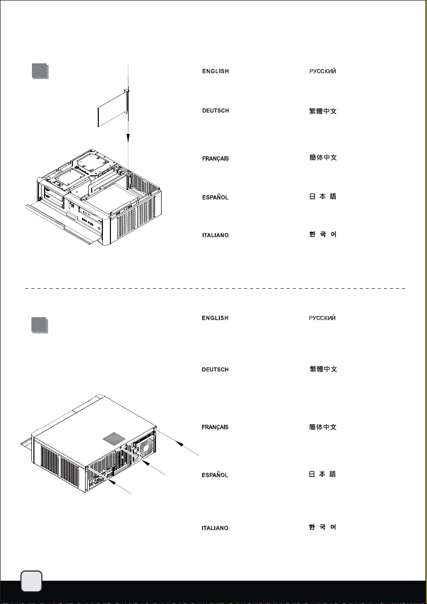
21
22
Install and secure required
expansion cards.
Installieren und befestigen Sie die
erforderlichen Erweiterungskarten.
Installez et fixez les cartes
d'extension requises.
Instale y fije las tarjetas de
expansión necesarias.
Installare ed assicurare le schede
di espansione necessarie.
Place the top cover back onto the
case and secure with three screws.
Установите и закрепите
необходимые платы расширения.
將介面卡插上。
将适配卡插上。
必要とされる拡張カードをイン
ストールし、固定します。
필요한 확장카드를 설치하고
고정시킵니다.
Уст ан ов ит е на место ве рхнюю
крышку корпуса и закрепите ее
тремя шурупами.
15
Setzen Sie die obere Abdeckung
wieder auf das Gehäuse auf,
fixieren Sie die Abdeckung mit
drei Schrauben.
Remettez le panneau supérieur sur
le boîtier et fixez-le avec trois vis.
Vuelva a poner la cubierta superior
en la carcasa y asegúrela con tres
tornillos.
Riposizionare il cover superiore e
serrarlo per mezzo delle tre viti.
將上蓋板蓋回去,並鎖固三顆螺絲。
将上盖板盖回去,并锁固三颗螺丝。
ケースに上部カバーを戻し、ネジ
3本で固定します。
상부 커버를 케이스에 재 설치한
후 3개의 나사로 고정시킵니다.
Page 17
lnstallation Guide
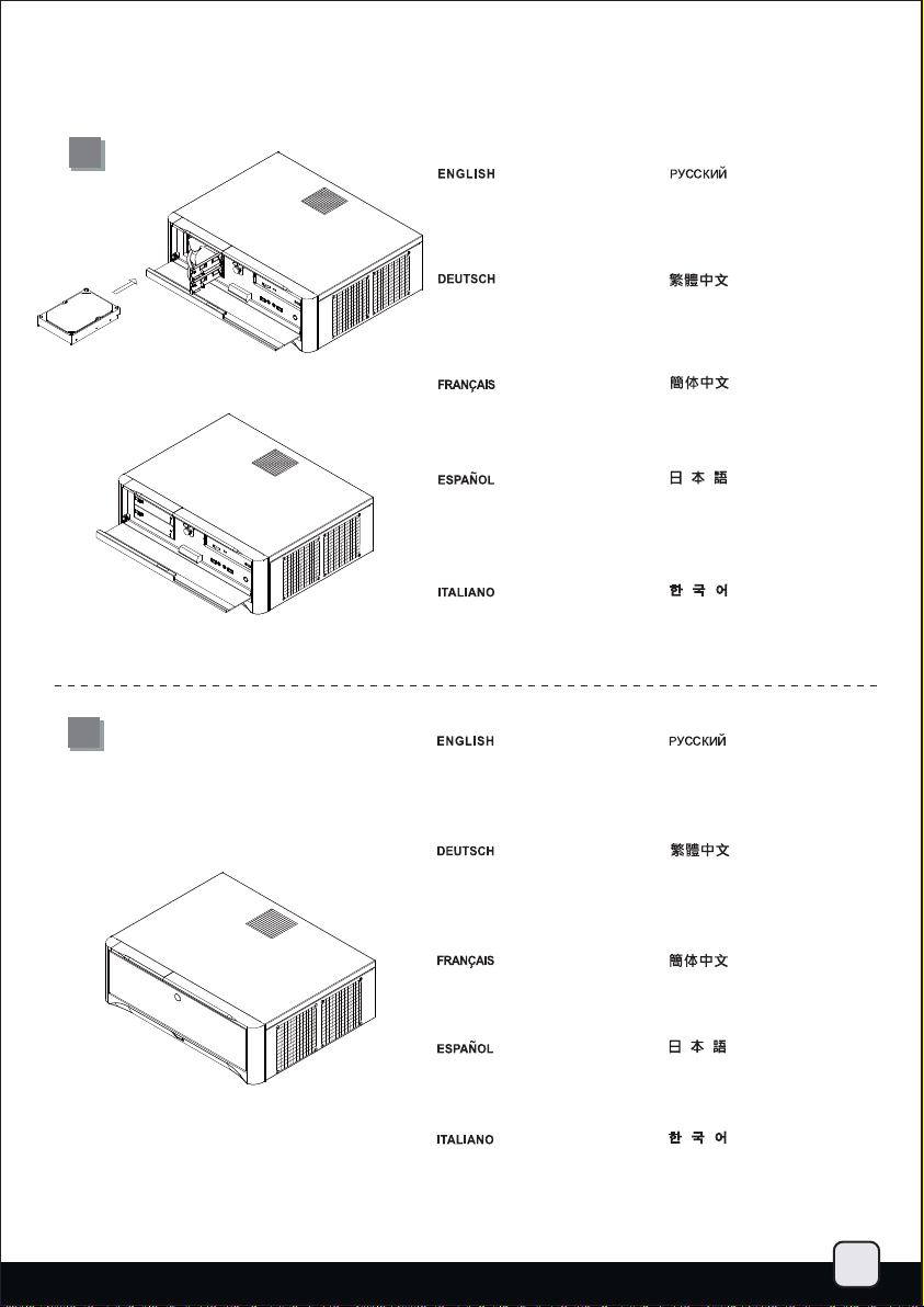
23
Install the hard drive into the hotswappable drive racks and place
the front cover back.
Установите жесткие диски в отсеки
для жестких дисков с возможностью
«горячей» замены и установите на
место переднюю крышку.
24
Installieren Sie die Festplatte in den
Hot-Swapping-fähigen FestplattenRacks; bringen Sie die Frontblende
wieder an.
Installez un disque dur dans un des
racks hot-swappable et remettez le
cache frontal.
Instale el disco duro en el espacio
para discos duros cambiables en
caliente y vuelva a colocar el panel
frontal en su sitio.
Installare gli hard disk nel rack hotswappable e riposizionare il cover
frontale.
Installation complete.
Die Installation ist damit
abgeschlossen.
打開硬碟熱插拔的門板,
將硬碟塞入再蓋回門板。
打开硬盘热插拔的门板,
将硬盘塞入再盖回门板。
ハードドライブをホットスワップ
対応ドライブラックに装着してか
ら、フロントカバーを戻します。
하드 드라이브를 핫스왑 드라이브
랙에 설치한 후에 전면커버를 다시
장착합니다.
Сборка завершена.
安裝完成。
Installation terminée.
Instalación finalizada.
Installazione completata.
安装完成。
インストールは完了です。
설치가 완료 되었습니다.
16
Page 18

Connector definition
(1) Front panel connector installation
Power switch and reset switch installation guide:
Please refer to the motherboard manuals for the motherboard’s “Front Panel
Connector” or “System Panel Connector” pin definition. Power switch and
reset switch have no polarity, so they can be connected in any orientation.
Ein-/Ausschalter und Rücksetztaste (Reset) installieren:
Bitte suchen Sie in der Motherboard-Dokumentation nach der Pinbelegung
der Anschlüsse des Frontbedienfeldes („Front Panel Connectors“ oder „
System Panel Connectors“). Ein-/Austaste und Rücksetztaste benötigen
keine bestimmte Polarität, können daher beliebig (ohne auf + und - zu achten)
angeschlossen werden.
Guide d'installation des interrupteurs d'allumage et de réinitialisation:
Veuillez-vous référer au manuel de votre carte mère pour la description des broches
"des connecteurs du panneau frontal" et des broches "des connecteurs du panneau
système". Les interrupteurs d'allumage et de réinitialisation ne possède pas de polarité,
donc ils peuvent être branché dans les deux sens.
Guía de instalación de los interruptores de encendido y reseteo:
Por favor, consulte en los manuales de la placa base la configuración de
pines del “Conector de panel frontal” ó “Conector de panel de sistema” de su
placa base. Los interruptores de encendido y reseteo no tienen polaridad,
luego se pueden conectar con cualquier orientación.
Guida all’installazione dei connettori Power Switch e Reset Switch:
Fare riferimento al manuale della scheda madre nella sezione “Connettori del
pannello frontale” o “Connettori del pannello di sistema”. Power switch e reset
switch non hanno polarità, posso essere pertanto connessi con qualsiasi
orientamento.
Инструкция по подключению выключателя питания и кнопки перезагрузки (reset):
Описание контактов разъемов приведены в разделах “Разъемы передней
панели” или “Разъемы системной панели” руководства пользователя
материнской платы. Выключатель питания и кнопка перезагрузки не имеют
полярности, поэтому их можно подключать в любой ориентации.
Power Switch 與Reset Switch
請參考說明書的Front Panel Connectors
Power Switch 與Reset Switch並無正負極性之分,反插正插都不影響功能性。
Power Switch与Reset Switch安装说明:
请参考说明书的Front Panel Connectors安装Pin Define,将Connector插上;
Power Switch与Reset Switch并无正负极性之分,反插正插都不影响功能性。
電源スイッチおよびリセットスイッチのインストールガイド:
マザーボードの「フロントパネルコネクタ」または「システムパネルコネクタ」
のピン配列についてはマザーボードマニュアルを参照してください。電源スイッ
チとリセットスイッチに極性はないので、いずれの方向でも接続できます。
파워 스위치 및 리셋 스위치 설치 가이드:
메인보드 매뉴얼의 전면패널 커넥터 혹은 시스템패널 커넥터 핀을 참조하기
바랍니다. 파워 스위치와 리셋 스위치는 극성이 없어 어떤 방향으로
설치해도 무방합니다.
安裝說明:
安裝Pin Define,將Connector插上;
17
LED connector installation guide:
Please refer to the motherboard manuals for the motherboard’s “Front Panel Connector
” or “System Panel Connector” pin definition.;the white wires are negative while other
colors are positive wires. The Power LED wires are separate pins for compatibility with
different motherboard pin definition so please make sure they are connected in the
right polarity by referring to your motherboard manual.
LED-Verbinder installieren:
Bitte suchen Sie in der Motherboard-Dokumentation nach der Pinbelegung der Anschlüsse
des Frontbedienfeldes („Front Panel Connectors“ oder „System Panel Connectors“).
Die weißen Adern sind negativ (-), die farbigen Adern positiv (+).Die Kabel für die
Betriebsanzeige-LED sind zur Kompatibilität mit unterschiedlichsten Motherboards einzeln,
nicht als kompletter Stecker ausgeführt. Achten Sie hier bitte auf die richtige Polarität, lesen
Sie in der Dokumentation Ihres Motherboards nach.
Guide d'installation du connecteur LED:
Veuillez-vous référer au manuel de votre carte mère pour la description des broches "des
connecteurs du panneau frontal" et des broches "des connecteurs du panneau système".
Les câbles colorés en blanc sont négatifs alors que ceux d'une autre couleur sont positifs.
Les câbles de la LED Power sont séparés afin d'être compatible avec différentes cartes mères,
donc vérifiez bien qu'ils sont branchés avec la bonne polarité en vous référant au manuel de
votre carte mère.
Guía de instalación del conector LED:
Por favor, consulte en los manuales de la placa base la configuración de pines del
“Conector de panel frontal” ó “Conector de panel de sistema” de su placa base. Los
cables de color blanco son negativos mientras que los de color son positivos.Los
cables LED de potencia tienen pines separados para compatibilidad con diferentes
definiciones de pines de la placa base luego por favor, asegúrese de que están
conectados en la polaridad correcta consultando el manual de su placa base.
Guida all’installazione del connettore LED:
Fare riferimento al manuale della scheda madre nella sezione “Connettori del
pannello frontale” o “Connettori del pannello di sistema”. I cavi di colore bianco sono il
polo negativo, mentre quelli di colore diverso il positivo.
Инструкция по подключению коннектора для светодиодного индикатора питания:
Описание контактов разъемов приведены в разделах “Разъемы передней панели”
или “Разъем ы системной панели” руководства пользователя материнской платы.
Белые провода - отрицательной полярности, цветные провода - положительной
полярности. Провода светодиодного индикатора питания имеют отдельные
контакты для совместимости с различными типами контактов материнских плат,
поэтому обратитесь к
что полярность соблюдена.
LED接頭安裝說明:
請參考主機說明書的Front Panel Connectors安裝Pin Define,將Connector插上;
白色線的部分為負極,彩色線的部分是正極。Power LED為了適應各主機板的不同,
特別設計為散Pin樣式,請安心使用。
LED接口安装说明:
请参考说明书的Front Panel Connectors安装Pin Define,将Connector插上;
白色线的部份为负极,彩色线的部份为正极。Power LED为了适应主机板的不同,
特别设计为散Pin样式,请安心使用。
LEDコネクタのインストールガイド:
マザーボードの「フロントパネルコネクタ」または「システムパネルコネクタ」
ピン配列についてはマザーボードマニュアルを参照してください。白色のリード線
はマイナスで、色の着いたリード線がプラスです。電源LEDリード線は種々のマザー
ボードピン定義と互換性を持たせるため分離されたピンとなっているので、ご使用の
マザーボードマニュアルを参照して、適切な極性に接続されるようお確かめください。
LED 커넥터 설치 가이드:
메인보드 매뉴얼의 전면패널 커넥터 혹은 시스템패널 커넥터 핀을 참조하기 바랍니다.
하얀선의 경우 음극이며, 다른 색의 경우 양극입니다. 파워 LED 선은 분리되어 다양한
메인보드에서 동작할 수 있도록 되어 있습니다. 그러므로 메인보드 매뉴얼을 참조하여
올바를 극성을 주의해 선택하시기 바랍니다.
руководству пользователя материнской платы и убедитесь,
Page 19
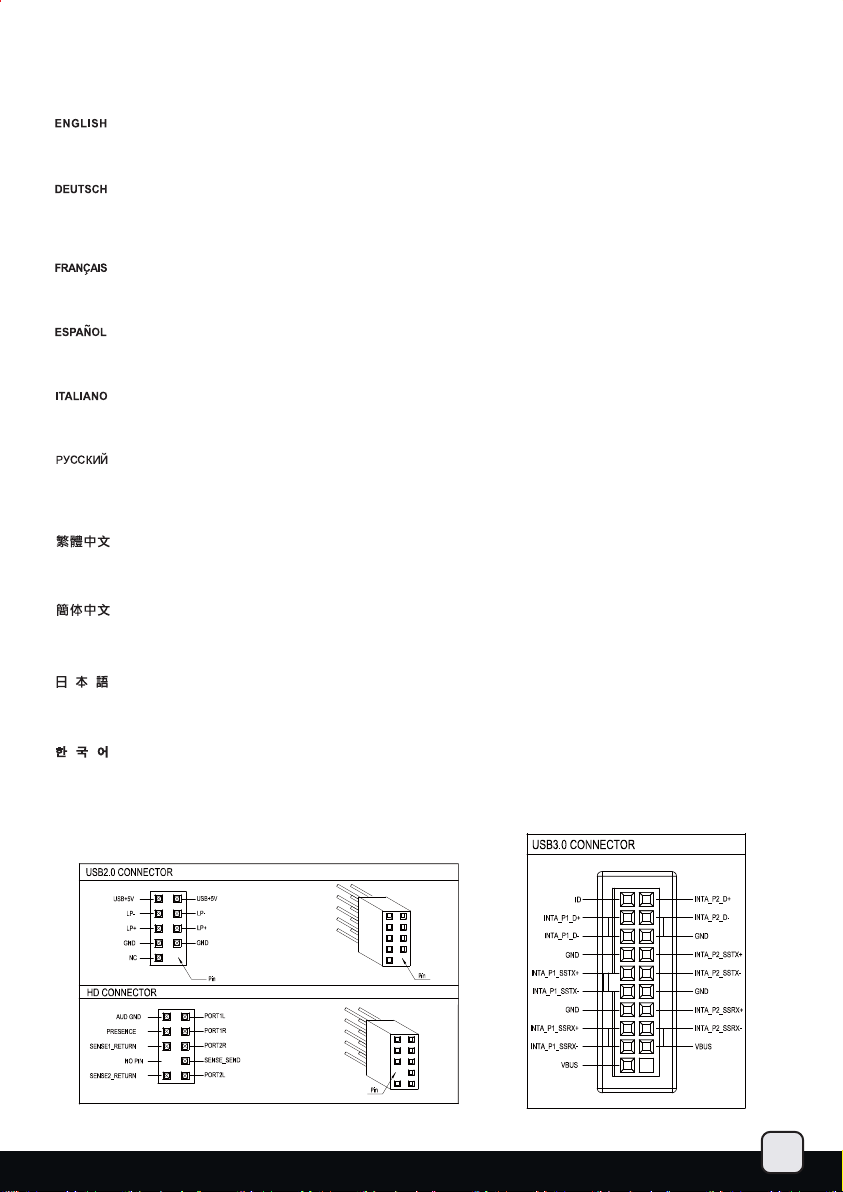
Front I/O connector guide
Below are the front I/O connectors pin definition, please also check your motherboard manual to cross reference with motherboard’s front
I/O pin headers. SilverStone’s I/O connectors are in block type to simplify installation.
Nachstehend finden Sie die Pinbelegung der Front-I/O-Verbinder; bitte gleichen Sie diese Angaben mit der Belegung der
Front-I/O-Anschlüsse ab – diese Angaben finden Sie in Ihrer Motherboard-Dokumentation. Zur einfacheren Installation sind
die SilverStone-I/O-Verbinder in einem kompletten Block zusammengefasst.
Au dessous de la description des broches des ports d'E/S, veuillez aussi vérifier sur le manuel de votre carte mère de manière croisée que
les broches sont correctement placées. Les connecteurs d'E/S de SilverStone sont en bloc pour en simplifier leur installation.
A continuación tiene la definición de pines de los conectores frontales de E/S, también debe consultar el manual de su placa base para
comprobar la referencia de los pines para E/S frontales. Los conectores de E/S de SilverStone son de bloque para simplificar la instalación.
Di seguito lo schema delle connessioni I/O frontali, confrontare lo schema con quanto riportato sul manuale della scheda madre per effettuare
una controllo incrociato. I connettori I/O Silverstone, per semplificare l’installazione, sono del tipo “a blocco”.
Ниже приведено описание контактов передних разъемов ввода/вывода. Обратитесь также к руководству пользователя материнской
платы за описанием передних разъемов ввода/вывода типа "пин-хедер". Разъем ы ввода/вывода "SilverStone" - блоч ного типа, что
облегчает сборку.
下表為Front I/O Connectors的Pin Define,請參閱主機板說明書的各Front I/O Connectors Pin Define一一核對。GD06的Front I/O Connectors
完全採用集合
下表为Front I/O Connectors的Pin Define,请参阅主机板说明书的各Front I/O Connectors Pin Define一一核对。GD06的Front I/O Connectors
完全采用集合Pin方式以简化安装。
Pin方式以簡化安裝。
以下はフロントI/Oコネクタピン配列ですが、お持ちのマザーボードのフロントI/Oピンヘッダは、マザーボードマニュアルをご参照ください。
シルバーストーンのI/Oコネクタは、インストールの容易なブロックタイプになっています。
아래는 전면 I/O 커넥터의 핀 사양이 나타나 있습니다. 메인보드 매뉴얼을 참조하여, I/O핀 을 재차 확인합니다. SilverStone의 I/O 커넥터는
블록으로 되어 있어 설치가 용이합니다.
18
Page 20
Component size limitations
The GD06 was designed to be as small as possible while maximizing interior space usage, please refer to the following guidelines for
component selection and future upgrade considerations.
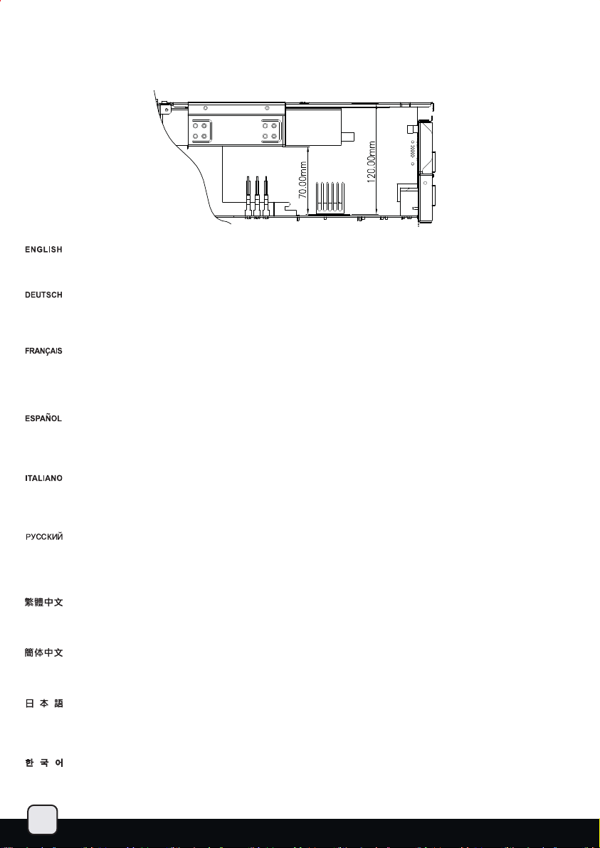
CPU cooler height limitation
When optical drive is used, the GD06 has 70mm height limitation for CPU cooler. If no optical drive is installed, the height limit for CPU cooler
increases to 120mm. If a silent CPU cooling solution is required, we recommend using the SilverStone NT01-E in fanless configuration for 65W
rated or lower CPUs. If you need more space for a larger CPU cooler, we recommend using SilverStone's TS03 (only accepts slim optical drive).
Wenn Sie ein optisches Laufwerk verwenden, darf der CPU-Kühler beim GD06 maximal 70 mm hoch sein. Falls kein optisches Laufwerk installiert
wird, können Sie CPU-Kühler mit einer Höhe bis 120 mm verwenden. Sofern Sie auf eine lautlose CPU-Kühlung Wert legen, empfehlen wir für CPUs
bis 65 W den Kühler SilverStone NT01-E in lüfterloser Ausführung. Falls Sie aufgrund eines größeren CPU-Kühlers mehr Platz benötigen, empfehlen
wir die Nutzung des TS03 von SilverStone (nur mit schmalem optischem Laufwerk kompatibel).
Lorsque l'emplacement du lecteur optique est utilisé, le GD06 peut accueillir un dissipateur de processeur de d'une hauteur de 70mm. Su aucun
lecteur optique n'est installé, le dissipateur du processeur peut avoir une hauteur de 120mm. Si une solution de refroidissement silencieuse est
requise, nous recommandons l'utilisation du SilverStone NT01-E dans une configuration sans ventilateurs pour les processeurs de 65W ou moins.
Si vous avez besoin de plus d’espace pour un dissipateur de processeur plus grand, nous vous recommandons l’utilisation du TS03 de SilverStone
(pouvant seulement accueillir des lecteurs slim).
Cuando se usa un dispositivo óptico, la GD06 tiene una limitación de altura de 70mm para el disipador de la CPU. Si no se instala un dispositivo
óptico, la limitación de altura para el disipador de la CPU sube hasta 120mm. Si se necesita una solución de refrigeración silenciosa para la CPU,
recomendamos usar la configuración sin ventilador SilverStone NT01-E para CPUs que usen 65V o menos. Si necesita más espacio para un
disipador de CPU más grande, le recomendamos usar el Silverstone TS03 (sólo acepta dispositivo óptico delgado).
Quando vengono utilizzati drive ottici, il GD06 può accogliere dissipatori alti max 70mm. Se non vengono utilizzati drive ottici la misura sale a
120mm. Se è necessaria una configurazione silenziosa, vi suggeriamo di utilizzare il dissipatore SilverStone NT01-E in configurazione fanless
per cpu da 65W o meno. Se avete bisogno di spazio per poter utilizzare dissipatori per CPU di maggiori dimensioni, vi raccomandiamo di adottare
il SilverStone TS03 (accetta soltanto drive ottici di tipo slim).
Если используется оптический привод, то максимальная высота кулера ЦП для корпуса GD06 - 70 мм. Если оптический привод не
установлен, то максимальная высота кулера ЦП увеличивается до 120 мм. Если требуется бесшумное охлаждение ЦП, мы
использовать SilverStone NT01-E без вентилятора для ЦП номинальной мощности 65 Вт и ниже. Если требуется больше пространства
для более крупного процессорного кулера, рекомендуется использовать модель SilverStone TS03 (допускает установку только тонкого
оптического привода).
GD06在光碟機涵蓋的部分CPU Cooler限高為70mm,在光碟機沒有涵蓋的部分CPU Cooler限高為120mm。
如果需要安靜的CPU Cooler,我們建議你可以使用NT01-E Fanless可以支援65W的CPU
如果需要擴大
GD06在光驱涵盖的部分CPU Cooler限高为70mm,在光驱没有涵盖的部分CPU Cooler限高为120mm。
如果需要安静的CPU Cooler,我们建议你可以使用NT01-E Fanless可以支持65W的CPU
如果需要扩大CPU Cooler的可安装空间,建议您可以选购SST-TS03(需要用到薄型光驱)
光学ドライブが使われる時、GD06はCPUクーラーに対して70mmの高さ制限があります。いずれの光学ドライブもインストールされないな
らば、CPUクーラーのための高さ制限は120mmまで増大します。静かなCPU冷却ソリューションが必要とされているならば、定格65W以下
のCPUを対象として、ファンレス構成でシルバーストーンNT01-Eを使うようお勧めします。大型CPUクーラー用にさらなるスペースが必要
な場合は、SilverStone製TS03(スリム光学ドライブのみに対応)の使用をお勧めします。
광드라이브 사용시에 GD06는 70mm 까지의 CPU 쿨러 사용이 가능하며, 광드라이브를 사용하지 않을 경우 CPU 쿨러의 높이 제한은 120 mm
로 늘어납니다. 무소음 CPU 냉각 솔루션이 필요할 경우 SilverStone의 NT01-E 를 무팬 상태로 사용하시길 권장합니다. 만약 더 큰 CPU 쿨러
장착이 필요하다면, SilverStone의 TS03을 추천합니다. (TS03은 슬림 광드라이브만 지원합니다. )
CPU Cooler的可安裝空間,建議您可以選購SST-TS03(需要用到薄型光碟機)
рекомендуем
19
Page 21
150mm
Power supply length limitation
The allowable power supply length is determined by the left intake fan size. Please refer to the table below as a guide when choosing the
appropriate power supply.
A. Depth limitation
The GD06 supports power supply with depth of up to 150mm.
The modular cable power supply might interfere with the hot-swappable hard drive racks. Please make sure they will not interfere with each
other. We recommend installing SilverStone's ST50F-P (140mm deep) power supply upside-down.
B: Cable length recommendations:
Below is a table of recommend cable length based off of common retail power supplies. Please make sure that the power supply you want
to use has long enough cables to fit the below recommendations or you can also choose to purchase additional power cable extensions.
The table shows the length recommended for a power supply with cables coming out from the right side of the power supply casing (with the
power supply’s 120mm fan facing down):
A. Maximaltiefe
Das GD06 unterstützt Netzteile mit einer Maximaltiefe von 150 mm.
Das Netzteil mit modularer Kabelverwaltung kann den Hot-Swapping-fähigen Festplatten-Racks ins Gehege kommen. Bitte stellen Sie sicher,
dass sich die Komponenten nicht gegenseitig beeinträchtigen. Wir empfehlen, das Netzteil ST50F-P (140 mm Tiefe) von SilverStone umgedreht
(„auf dem Kopf“) zu installieren.
B: Empfohlene Kabellänge:
Nachstehend finden Sie eine Tabelle der empfohlenen Kabellänge basierend auf handelsüblichen Netzteilen. Bitte stellen Sie sicher, dass
das von Ihnen gewählte Netzteil entsprechend der nachstehenden Empfehlungen über ausreichend lange Kabel verfügt; alternativ können
Sie zusätzliche Netzkabelverlängerungen kaufen. Die Tabelle zeigt die empfohlene Länge bei einem Netzteil mit Kabeln, die aus der rechten
Seite des Netzteilgehäuses herauskommen (der 120 mm-Lüfter des Netzteils zeigt nach unten):
A. Limitation en profondeur
Le GD06 est compatible avec les alimentations ayant une profondeur jusqu'à 150mm.
Les alimentions à câblage modulaire peuvent être en conflit avec les racks hot-swappable. Veuillez bien vérifier qu’ils peuvent être montés ensemble.
Nous vous recommandons d’installer une alimentation ST50F-P de SilverStone (140mm de profondeur) à l'envers.
B. Longueur des câbles:
Vous avez ci dessous un tableau avec la longueur des câbles recommandés basé sur les alimentations du marché. Veuillez bien vérifier que
l'alimentation que vous allez utiliser possède bien des câbles assez long pour être compatible avec ces recommandations. Sinon vous pouvez
choisir d'acheter des rallonges. Le tableau montre la longueur des câbles recommandées pour une alimentation qui a les câbles sortant du côté
droit du boîtier (avec le ventilateur de 120mm vers le bas):
A: Limitaciones de profundidad
La GD06 acepta fuentes de alimentación con una profundidad de hasta 150mm.
La fuente de alimentación con cables modulares podría interferir con los espacios para discos duros cambiables en caliente. Por favor, tenga
cuidado para no entorpecerse. Le recomendamos que instale la fuente de alimentación Silverstone ST50F-P (profundidad de 140mm) hacia abajo.
B: Recomendaciones para la longitud del cable:
A continuación hay una tabla con la longitud recomendada de los cables basada en fuentes de alimentación comunes. Por favor, asegúrese de
que la fuente de alimentación que quiere usar tiene cables lo bastante largos como para adecuarse a las recomendaciones siguientes, en caso
contrario puede decidir comprar extensiones adicionales para cables de potencia. La tabla muestra la longitud recomendada para una fuente de
alimentación con cables que salgan del lado derecho de la carcasa de la fuente de alimentación (con el ventilador de 120mm de la fuente de
alimentación hacia abajo):
A. Limitazione di profondità
GD06 supporta alimentatori con profondità massima di 140mm.
Un alimentatore modulare potrebbe interferire con il rack per hard disk hot-swappable. Assicuratevi che ciò non avvenga. Vi raccomandiamo
di installare l’alimentatore SilverStone ST50F-P (140mm di profondità) rovesciato.
B. Misure dei cavi raccomandate.
La tabella di seguito mostra le lunghezze dei cavi raccomandate e si basa sulle misure dei cavi con riferimento ai comuni alimentatori retail.
Assicuratevi che l’alimentatore che avete intenzione di utilizzare risponda alle caratteristiche richieste, altrimenti considerate l’acquisto di un
kit di prolunga cavi. La tabella mostra le misure consigliate prendendo in considerazione un alimentatore con le connessioni situate sulla parte
destra dello chassis ( con la ventola da 120mm rivolta verso il basso).
20
Page 22
A. ограничение по глубине
GD06 поддерживает источники питания с глубиной не более 150 мм.
Блок питания с модульными кабелями может помешать установке отсеков для жестких дисков с возможностью «горячей» замены.
Удостоверьтесь, что они не мешают друг другу. Рекомендуется устанавливать блок питания SilverStone ST50F-P (глубиной 140 мм)
в перевернутом положении.
B. рекомендации
В следующей таблице представлены рекомендованные значения длины кабелей на основе значений имеющихся в продаже
источников питания. Убедитесь, что длина кабелей источника питания достаточна и соответствует следующим рекомендациям,
в противном случае можно приобрести дополнительные удлинители кабеля источника питания. В таблице указаны рекомендованные
значения длины кабелей источника питания при условии, что кабели выходят из правой стороны корпуса источника питания (вентилятор
120 мм источника питания направлен вниз):
A: PSU長度限制為150mm
模組化電源供應器因為接頭可能會與熱插拔硬碟架干涉,可能不能安裝,如果您必須使用模組化的電源供應器我們建議您先確認模組化的插
座位置會不會干涉;我們建議選用ST50F-P並將電源反向安裝。
B: 電源線材建議長度:
以下是以一般市售主機板與電源抓出來的各線材建議長度列表,請先確認電源線長度是否足夠, 如果不夠請選購所需要的延長線。
本表是以電源出線端在右方的電源(此時120mm風扇應當朝下)為假設條件。
A: PSU长度限制为150mm
模块化电源供应器因为接头可能会与热插拔硬盘架干涉,可能不能安装,如果您必须使用模块化的电源供应器我们建议您先确认模块化的插
座位置会不会干涉;我们建议选用ST50F-P并将电源反向安装。
B:电源线材建议长度:
以下是以一般市售主机板与电源抓出来的各线材建议长度列表,请先确认电源线长度是否足够, 如果不够请选购所需要的延长线。
本表是以电源出线端在右方的电源(此时120mm风扇应当朝下)为假设条件。
A: 奥行き制限
GD06は最大奥行き150mmの電源をサポートします。
モジュラーケーブル電源装置がホットスワップ対応ハードドライブラックと位置がかぶる場合があります。お互いに場所がかぶらないこと
を確認してください。SilverStone製ST50F-P
B: 推奨ケーブル長さ
下記は、一般の小売り電源の推奨ケーブル長さの表です。使いたい電源が下記の推奨基準に合った、十分の長さのケーブルを持っているこ
とを確認してください。または電源用の延長ケーブルを購入することもできます。表では、推奨ケーブル長は電源ケースの右側(電源の
120mmファンは下向き)から出ているケーブルの長さが示されています。
по длине кабелей
(奥行き140mm)電源を逆さまに設置することをお勧めします。
A. 깊이 제한
GD06은 150mm 깊이까지의 파워 서플라이를 지원합니다.
모듈러 파워서플라이 케이블이 핫스왑 하드 드라이브랙과 간섭될 수 도 있습니다. 서로 간섭이 되지 않도록 유의하시기 바랍니다.
SilverStone의 ST50F-P (140mm 깊이)을 거꾸로 장착하는 것을 권장합니다.
B. 추천 케이블 길이
표에서는 일반적으로 판매되는 파워 서플라이의 추천 케이블 길이를 표시해 놓았습니다. 사용하고자 하는 파워 서플라이가 아래의
아래
추천길에에 충분한 케이블을 갖추고 있는지 확인하시기 바라며, 필요시에는 추가의 연장 파워 케이블 구입이 가능합니다. 아래 표는 파워
서플라이의 오른쪽에서 나오는 케이블의 길이를 나타낸것입니다. (이 경우 파워 서플라이의 120mm 팬은 아래를 향합니다. )
Cable type and location
EPS 8pin/ATX4pin (over the motherboard)
EPS 8pin/ATX4pin (in front of the motherboard)
ATX 24Pin(over the motherboard)
ATX 24Pin(in front of the motherboard)
SATA 15Pin to optical drive
SATA 15Pin to hard drive on optical drive bracket
SATA 15Pin to left front 2.5” drive
SATA 15Pin to left rear 3.5” drive
4-Pin Peripheral to hot-swap drive
Minimum length
400mm
670mm
300mm
350mm
550mm
330mm
100mm
150mm
0mm
21
Page 23
Graphics card/expansion card length limitation
GD06 can support 11” (280mm) consumer level graphics cards
Graphic card length reference:
AMD Radeon HD 5870 11"
AMD Radeon HD 6870 10.5"
NVIDIA GeForce GTX580 - 10.5"
NVIDIA GeForce GTX480 - 10.5"
AMD Radeon HD 5850 - 9.5"
NVIDIA GeForce GTX470 - 9.5"
AMD Radeon HD 6850 9"
Memory / RAM module height limitation
CD-ROM
53mm
78mm
MICRO ATX M/B
(OPTION)
From the motherboard to the optical cage with a 3.5” hard drive, the maximum height of the DRAM modular is 53mm.
The maximum height will extend to 78mm if you choose not to install a 3.5” hard drive.
Vom Motherboard bis zum optischen Käfig mit einer 3,5 Zoll-Festplatte beträgt die maximale Höhe des DRAM-Moduls 53 mm.
Die maximale Höhe lässt sich auf 78 mm erweitern, wenn Sie keine 3,5 Zoll-Festplatte installieren.
De la carte mère au casier du lecteur optique avec un disque dur de 3.5”, la hauteur maximale des modules est de 53mm.
La hauteur maximale peut être étendu à 78mm si vous choisissez de ne pas installer de disque dur 3.5”.
Desde la placa base hasta la carcasa óptica con un disco duro de 3,5”, la altura máxima del módulo DRAM es de 53mm.
La altura máxima aumentará a 78mm si decide no instalar un disco duro de 3,5”.
Dalla scheda madre fino al supporto per drive ottici con installato un hard drive da 3.5” la massima altezza consentita per il
moduli di memoria è di 53mm, che si estende a 78mm se decidete di non installare un hard drive da 3,5”.
Максимальная высота модулей DRAM, измеренная от материнской платы до кронштейна для оптического привода с
установленным 3,5-дюймовым жестким диском, составляет 53 мм. Максимальная высота увеличится до 78 мм, если
не будет установлен 3,5-дюймовый жесткий диск.
由主機板表面算起在光碟架下方有安裝3.5”硬碟之下,記憶體限高為53mm光碟架下方不安裝3.5”硬碟之下,記憶體限高為78mm。
由主机板表面算起在光盘架下方有安装3.5”硬盘之下,内存限高为53mm光盘架下方不安装3.5”硬盘之下,内存限高为78mm。
マザーボードから3.5”ハードドライブを装着した光学ドライブケージまで、DRAMモジュールの最大高さは53mmです。
3.5”ハードドライブを装着しない場合は、最大高さは78mmまで延ばせます。
메인보드에서 광드라이브 케이지 까지 3.5” 하드드라이브를 장착하고 최대 장착 가능한 DRAM 모듈의 높이는 53mm 입니다.
최대 높이는 3.5” 하드 드라이브를 장착하지 않는다면 78mm로 늘어 날 수 있습니다.
22
Page 24
Component size limitations on the front door
A.
18.8mm
A. The maximum clearance between the optical drive and the inner part of the front door is 18.8mm.
B. The maximum size of a USB device that can be inserted into the front USB port is 16mm.
A. In die CD-ROM-Öffnung passt ein Gerät mit einer maximalen Größe von 18,8 mm.
B. In den vorderen USB-Port kann ein USB-Gerät mit einer maximalen Größe von 16 mm eingesteckt werden.
A. La taille maximale qui conviendra à l'ouverture du CD-ROM est de 18.8mm.
B. La taille maximale des appareils USB pouvant être branché dans le port UUSB frontal est de 16mm.
A. El tamaño máximo que entrará en el espacio del CD-ROM es de 18,8mm.
B. El tamaño máximo de un dispositivo USB que pueda ser insertado en el puerto frontal USB es de 16mm.
A. La massima distanza tra il cdrom ed il portello frontale è di 18.8mm.
B. La misura massima di una periferica USB connessa alla porta frontale è di 16mm.
B.
16mm
A. Максимальный размер устройства, которое можно установить в отсек для привода CD-ROM, составляет 18,8 мм.
B. Максимальный размер USB-устройства, которое можно установить в передний порт USB, составляет 16 мм.
A. 光碟機表面凸起物限制最大高度為18.8mm。
B. USB常駐的隨插即忘介面,允許突出內面板表面16mm。
A. 光驱表面凸起物限制最大高度为18.8mm。
B. USB常驻的随插即忘接口,允许突出内面板表面16mm。
A. CDROM 입구에 맞을 수 있는 최대 크기는 18.8mm 입니다.
B. 전면 USB 포트에 삽입 할 수 있는 USB 장치의 최대 크기는 16mm 입니다.
A. CD-ROM開口部にフィットする最大サイズは18.8mmです。
B. フロントUSBポートに装着可能なUSB装置の最大サイズは16mmです。
23
Page 25
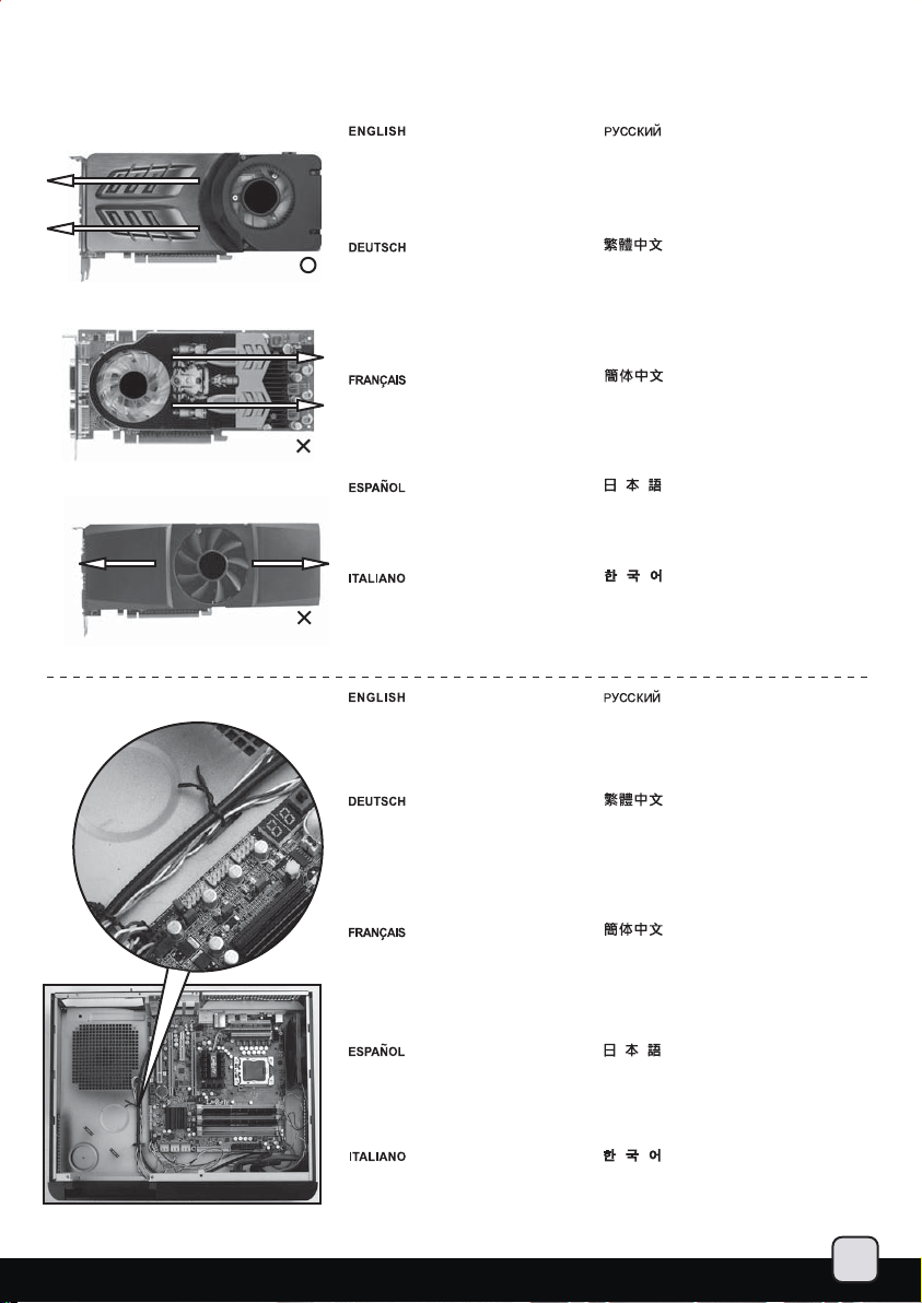
Recommended cooling device setup and selection
When choosing a graphics card, we recommend models that have fan blowing exhaust air to the rear slot, this will ensure smooth and
efficient airflow within the GD06 for maximum cooling performance.
Cable routing
When choosing a graphics card, we
recommend models that have fan
blowing exhaust air to the rear slot,
this will ensure smooth and efficient
airflow within the GD06 for maximum
cooling performance.
Bei der Auswahl von Grafikkarten
empfehlen wir Modelle, die warme
Luft über eine Öffnung im hinteren
Teil des Steckplatzes in die Außenwelt
ableiten; dies gewährleistet eine
ungestörte und wirksame Luftzirkulation
innerhalb des GD06 und sorgt für eine
optimale Kühlung.
Lorsque vous choisirez une carte graphique,
nous recommandons les modèles qui ont
des ventilateurs qui soufflent en extraction
par l'équerre arrière, ceci assurera un flux
d'air régulier et efficace dans le GD06 pour
des performances de refroidissement maximales.
Cuando escoja una tarjeta gráfica, le recomendamos
modelos que expulsen el aire hacia la parte posterior,
esto le asegurará un flujo de aire suave y eficiente
dentro de la GD06, consiguiendo un rendimiento
de refrigeración máximo.
Quando scegliete una scheda grafica, vi
raccomandiamo di optare per un modello
che espella l’aria al di fuori del case, questo
assicurerà un più efficiente flusso d’aria e
massimizzerà le prestazioni di raffreddamento
interno di GD06.
We placed pass-through holes in various
spots such as around the motherboard, in
front of the power supply, and next to the
hard drive, etc. Please use wire ties in
places as needed by your hardware configuration.
Мы рекомендуем выбирать такие модели
графических карт, у которых вентилятор
гонит отработанный воздух к заднему слоту.
Это обеспечивает беспрепятственную и
эффективную циркуляцию воздуха в корпусе
GD06 и максимальную защиту от перегрева.
如果您安裝高階顯示卡,我們建議您選擇風向為朝
向Slot端的方式,這樣安裝上GD06時,費熱會儘量
優先由機殼上蓋的開孔洩出,以避免機殼內的積熱。
如果您安装高端显示卡,我们建议您选购风向为朝
向Slot端的方式,这样安装上GD06时,废热会尽量
优先由机箱上盖的开孔泄出,以避免机箱内的积热。
グラフィックカードを選ぶ際、ファン送風が後部
スロット方向に排気を行うモデルを推奨します。
これはGD06の中にスムーズで効率的な気流を生
じ、最大の冷却性能を実現します。
그래픽 카드 선택시에 쿨링 팬이 확장슬롯 커버
방향으로 부는 제품을 선택하기를 권장하며,
이는 보다 부드럽고 효율적으로 GD06의 냉각
성능을 극대화 시킬수 있도록 보장하기
위함입니다.
Сквозные отверстия размещены в различных
местах, например, вокруг материнской платы,
перед блоком питания, рядом с жестким диском
и т.п. При необходимости пользуйтесь стяжками
для кабелей.
An verschiedenen Stellen des Gehäuses
-beispielsweise um das Motherboard herum,
vor dem Netzteil, neben den Festplatten und
an anderen Stellen – erleichtern
Durchführungsöffnungen das saubere
Verlegen der Kabel. Bitte setzen Sie
Kabelbinder an Stellen ein, an denen Ihre
Hardwarekonfiguration dies erlaubt.
Nous avons placés des trous pour faire passer
des câbles à plusieurs endroits comme par
exemple autour de la carte mère, à l'avant
de l'alimentation, et à côté des disques durs,
etc. Veuillez utilisez les système d'attache
déjà présent selon les besoins de votre
configuration matérielle.
Hemos situado agujeros de pasada en varios
puntos: cerca de la placa base, frente a la
fuente de alimentación y cerca del disco duro,
etc. Por favor, use bridas en los lugares que
considere necesarios según su configuración
de componentes.
Sono presenti dei fori passanti in vari punti,
come intorno alla scheda madre, frontalmente
all’alimentatore, nei pressi degli hard disk, ecc.
Usare le fascette in dotazione a seconda di
quanto richiesto dalla vostra configurazione.
我們有在主機板周邊,電源供應器前方,磁架上與顯
示卡前端安置可以容納束線帶的凸橋,請依指示將適
當的線材綁在適當的位置。
我们有在主机板周边,电源供应器前方,磁架上与显
示卡前端安置可以容纳束线带的凸桥,请依指示将适
当的线材绑在适当的位置。
マザーボードには、いくつかの穴が電源の前とハ
ードドライブの隣などケーブル用に用意されてい
ます。ご使用のハードウェア構成の必要に合わせ
て、ケーブルストラップを適所にご使用ください。
선정리를 하기 위해서는 파워서플라이 앞쪽이나
하드드라이브 주변의 홀을 이용합니다. 필요에
따라서는 알맞은 연결 위치를 만족시키기
위하여 메인보드 주변의 공간을 이용하여 선정리를
하시면 됩니다.
24
Page 26

Upgrading case fan
SilverStone already includes three 120mm low noise fans in the GD06. The fans are selected to maintain class-leading cooling performance
while keeping noise to minimum. If you wish to increase air exhaust speed around the CPU, there are two 80mm fan slots for adding additional
fans. For this, we recommend the use of SilverStone’s SUSCOOL81.
SilverStone setzt drei geräuscharme 120-mm-Lüfter im GD06 ein. Dabei handelt es sich um ausgesuchte Lüfter, die eine hervorragende
Kühlungsleistung bieten, aber dennoch besonders leise arbeiten. Falls Sie den Luftstrom um die CPU weiter verbessern möchten, stehen
Ihnen zwei Öffnungen für zusätzliche 80-mm-Lüfter zur Verfügung. Wir empfehlen die SilverStone-Lüfter SUSCOOL81.
SilverStone a déjà inclus trois ventilateurs silencieux de 120mm dans le GD06. Les ventilateurs ont été sélectionnés pour obtenir des
performances de refroidissement de première catégorie tout en garantissant un niveau sonore minimal. Si vous souhaitez augmenter
le débit d'air extrait autour du processeur, il y a deux emplacements pour ventilateur de 80mm pour des ventilateurs additionnels. Nous
vous recommandons d'utiliser des ventilateurs SilverStone SUSCOOL81.
SilverStone ya incluye tres ventiladores de 120mm de baja velocidad en la GD06. Los ventiladores están seleccionados para mantener el
rendimiento de la refrigeración a un nivel óptimo mientras la sonoridad sea mínima. Si desea incrementar la velocidad de salida de aire en
la CPU, hay dos zócalos para ventiladores de 80mm y así poder añadir ventiladores adicionales. Con este objetivo recomendamos el uso
del SUSCOOL81 de SilverStone.
Silverstone ha incluso nel GD06 3 ventole da 120mm a bassa rumorosità. Le ventole sono scelte in base al più alto livello qualitativo e la minima
rumorosità. Se desiderate incrementare l’espulsione d’aria nei pressi della CPU, sono presenti 2 sedi ove è possibile montare altrettante ventole
aggiuntive da 80mm. A questo scopo, vi consigliamo il modello SilverStone SUSCOOL 81.
Максимальная высота модулей DRAM, измеренная от материнской платы до кронштейна для оптического привода с установленным
3,5-дюймовым жестким диском, составляет 53 мм. Максимальная высота увеличится до 78 мм, если не будет установлен 3,5-дюймовый
жесткий диск.
SilverStone已經為您配置了3顆120mm低噪音風扇,以確保系統在任何配置下都能達到優良的散熱效能。如果您還想要增加CPU區塊的排風效能,
我們建議您可以購買我們的SUSCOOL 81兩顆,安置在機殼後方。
SilverStone已经为您配置了3颗120mm低噪音风扇,以确保系统在任何配置下都能达到优良的散热效能。如果您还想要增加CPU区块的排风效能,
我们建议您可以购买我们的SUSCOOL 81两颗,安置在机壳后方。
シルバーストーンは、すでに120mm低動作音ファン3台をGD06に装備させています。ファンは、動作音を最小に抑えつつ、クラスをリードす
る冷却性能を維持するよう選ばれています。 CPUのまわりで空気排気速度を上げることを望まれるなら、増設ファンを追加するための2つの
80mmのファンスロットが用意されています。このためには、シルバーストーン製SUSCOOL81をお勧めします。
GD06는 3개의 저소음 팬이 장착되어 있으며, 이 팬들은, 동급 최고의 냉각성능을 유지하면서도 소음은 최소화 할 수 있도록 엄선되었습니다.
만약 CPU주변의 배기량을 늘리고 싶다면, 2
선택을 권장합니다.
SUSCOOL81
개의 80mm 팬을 장착할 수 있는 슬롯이 마련되어 있습니다. 이 경우 SilverStone의 SUSCOOL81
25
Page 27

Cleaning of fan filters on a regular basis is highly recommended
GD06’s positive air pressure design is an effective configuration that will reduce dust buildup inside the case. Small air particles or lint will
accumulate over time on GD06’s intake filters instead of on the components inside the case. To maintain GD06’s excellent cooling performance
for years to come, we recommend to clean all fan filters regularly every three months or half a year (depending on your environment). Below are
steps to remove fan filters.
Bauartbedingt erzeugt das GD06 einen positiven Luftdruck, der Staubansammlungen im Gehäuse effektiv vorbeugt. Schwebeteilchen und Fusseln
sammeln sich im Laufe der Zeit in den Einlassfiltern des GD06, statt die Kühlung von Komponenten innerhalb des Gehäuses zu blockieren. Damit
die herausragende Kühlungsleistung Ihres GD06 auch über Jahre hinweg erhalten bleibt, sollten Sie sämtliche Lüfterfilter – je nach Einsatzumgebung
– alle drei Monate oder zumindest zweimal jährlich gründlich reinigen. Nachstehend finden Sie die nötigen Schritte zum Herausnehmen der Lüfterfilter.
[Translator's note: Steps are not mentioned below – these steps are mentioned ABOVE. Corrected translation: Weiter oben finden Sie die nötigen
Schritte zum Herausnehmen der Lüfterfilter.]
La conception de la pression positive du GD06 est une configuration efficace qui réduira l'accumulation de poussière à l'intérieur du boîtier. Les
petites particules flottant dans l'air s'accumuleront dans les filtres d'admission du GD06 plutôt que sur les composants à l'intérieur du boîtier.
Pour maintenir les excellentes performances de refroidissement du GD06 pour les années à venir, nous recommandons de nettoyer tous les
filtres de ventilateur régulièrement tous les trois mois ou tous les 6 mois (selon votre environnement). Ci dessous les étapes pour démonter les filtres.
El diseño de presión de aire positiva de la GD06 es una configuración efectiva que reducirá la acumulación de polvo dentro de la carcasa. Las
pequeñas partículas de polvo o pelusa se acumularán con el transcurso del tiempo en los filtros de entrada de la GD06 en lugar de en los
componentes del interior de la carcasa. Para mantener la excelente capacidad de refrigeración de la GD06 durante los años venideros, le
recomendamos limpiar todos los filtros de los ventiladores de forma regular cada tres meses o medio año (dependiendo del ambiente). A
continuación están los pasos para quitar los filtros de los ventiladores.
Un esempio di GPU cooler ricolmo di polvere, in queste condizioni ha perso gran parte del suo potere dissipante. Il design a pressione positiva
di GD06 riduce l’accumulo di polvere all’interno del case. Le piccole particelle di polvere presenti nell’aria vengono trattenute dai filtri invece di
depositarsi sui componenti interni.Per mantenere ai massimi livelli le prestazioni di raffreddamento di GD06 negli anni a venire, vi raccomandiamo
di pulire regolarmente i filtri delle ventole ogni 3/6 mesi ( dipendentemente dall’ambiente in cui si trova il case). Di seguito la procedura di rimozione
dei filtri delle ventole.
Положительное давление, создаваемое внутри корпуса GD06 благодаря его конструкции, препятствует образованию пыли. Со
временем небольшие частицы воздуха и пыль скапливаются на всасывающих фильтрах GD06, а не на компонентах внутри корпуса.
Чтобы охлаждающая способность GD06 сохранялась долгие годы
(в зависимости от окружающих условий) чистить все фильтры вентилятора. Ниже приведены этапы демонтажа фильтров вентиляторов.
GD06的正壓差搭配濾網方式是經的起時間考驗最有效的防塵方式。在使用相當長一段時間後,棉屑灰塵或其他可能妨礙散熱效能的小異物只會卡
在濾網,而不是電腦內的元件上面。我們重視的散熱效能,是在您使用電腦長達2~3年後還能維持與全新的無異。為了維持這種散熱效能您只需要
定期清理濾網,而不是電腦裡面的元件。視環境而定,我們建議您每3~6個月必須清理濾網,以下是濾網的拆卸步驟。
GD06的正压差搭配滤网方式是经的起时间考验最有效的防尘方式。在使用相当长一段时间后,棉屑灰尘或其它可能妨碍散热效能的小异物只会卡
在滤网,而不是计算机内的组件上面。我们重视的散热效能,是在您使用计算机长达2~3年后还能维持与全新的无异。为了维持这种散热效能您只
需要定期清理滤网,而不是计算机里面的组件。视环境而定,我们建议您每3~6个月必须清理滤网,以下是滤网的拆卸步骤。
GD06の正圧設計は、ケースの中で塵の蓄積を減らすのに有効な設定です。時間が経つにつれ、空気中の粒子または綿埃は、ケース内のコンポ
ーネント上ではなくGD06の吸気フィルタ上に蓄積します。この先何年もの間GD06の素晴らしい冷却性能を維持するために、すべてのファンフ
ィルタを3ヶ月または半年(ご使用の環境に依存)ごとに定期的に清掃するようお勧めします。以下は、ファンフィルタを取り外す手順です。
작은 부유 물이 케이스 내부의 부품에 쌓이는 대신 이 GD06의 흡기 필터에 쌓이게 됩니다. 지속적으로 GD06의 우수한 냉각 성능을 유지
시키기위해 3개월 혹은 6개월 마다(환경에 따라 다를 수 있습니다) 필터를 정기적으로 청소 하시기를 권장합니다. 아래는 팬 필터를
제거하기위한 단계별 과정입니다.
, мы рекомендуем регулярно каждые три месяца или полгода
26
Page 28

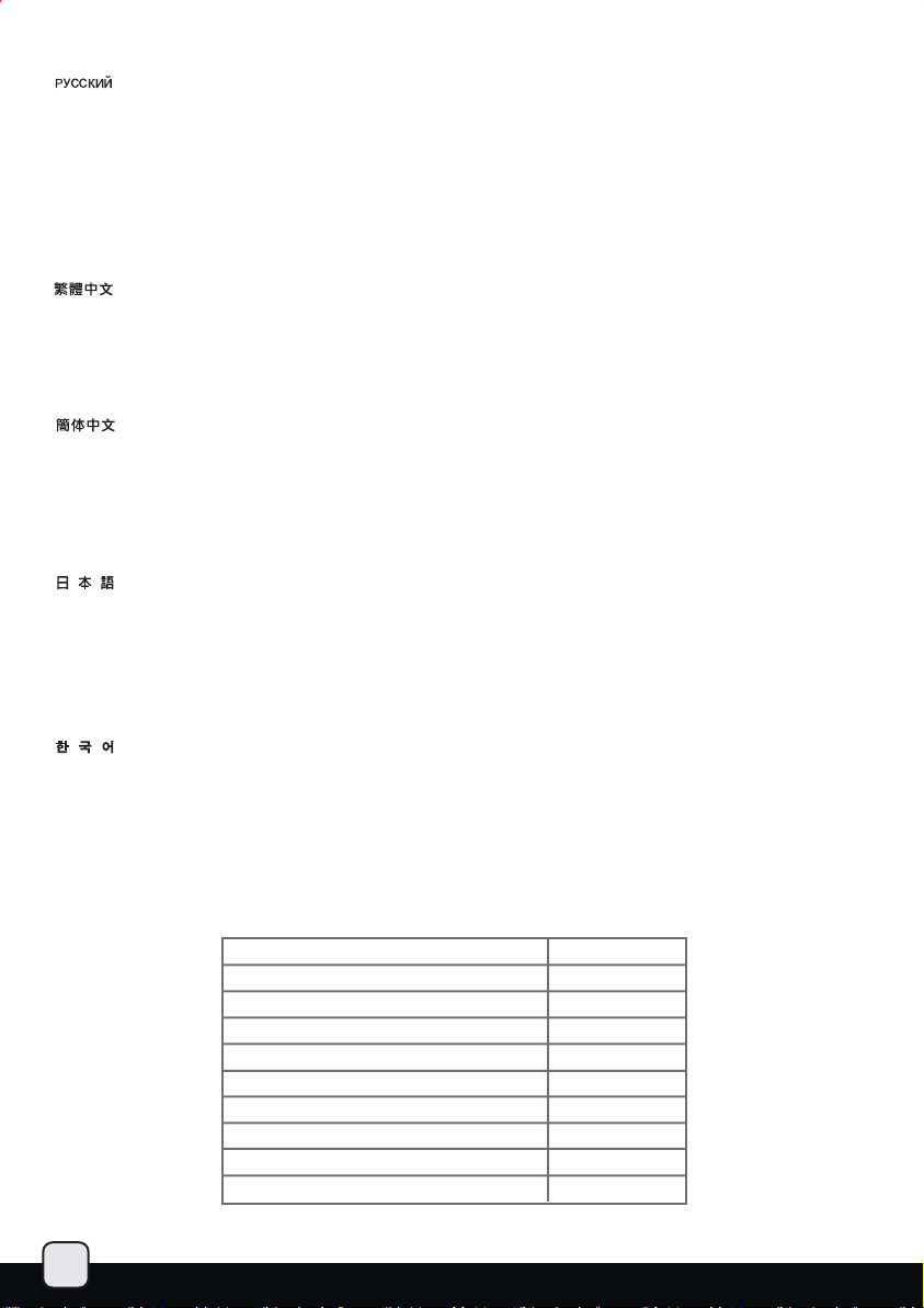
Upgrade and maintenance
Fan and fan filter disassembly guide
If you need to change fans, clean filters, or upgrade a fan, please refer to the following steps:
1
2
Refer to the case installation guide
to properly remove the drive bracket,
then loosen the fan screws to remove
the fans.
Nehmen Sie die Laufwerkhalterung
wie in der Dokumentation zum Gehäuse
beschrieben heraus, lösen Sie zum
Entfernen der Lüfter anschließend die
Lüfterschrauben.
Lisez le guide d'installation du boîtier
pour démonter correctement le casier
à lecteurs, puis desserrez les vis du
ventilateur pour le retirer.
Consulte la guía de instalación de la
carcasa para quitar de forma correcta
el bracket del dispositivo, luego afloje
los tornillos del ventilador para quitar
los ventiladores.
Fare riferimento alla guida di
installazione del case per rimuovere
in modo appropriato la staffa, quindi
allentare le viti della ventola per
rimuoverla.
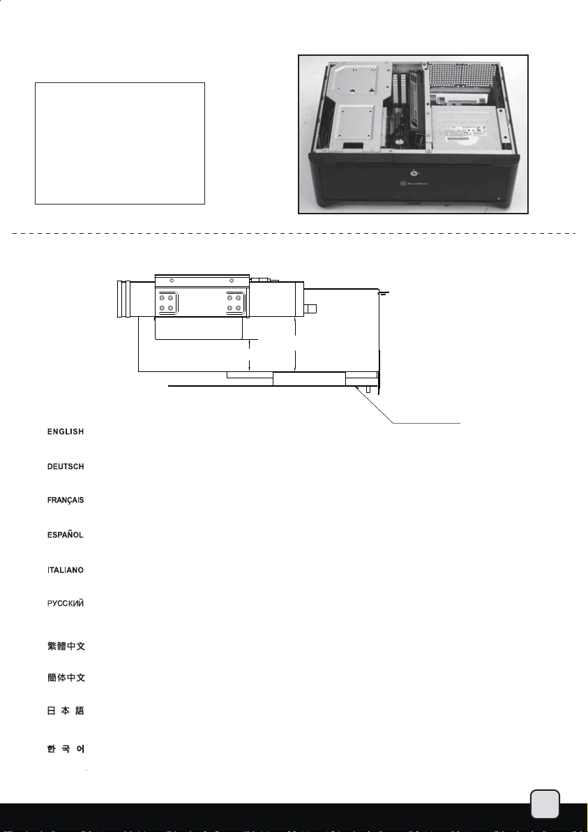
If the CPU cooler obstruct you from
removing the right rear fan, please
remove the right front fan first and
slide the rear one to the front to
remove it.
Чтобы правильно снять кронштейн
жесткого диска, обратитесь к
инструкции по сборке корпуса. Затем
открутите шурупы вентиляторов и
выньте вентиляторы.
參考機殼安裝步驟適當的將磁架移
除,並鬆開外部鎖固風扇的螺絲,將
風扇拆卸下。
参考机壳安装步骤适当的将磁架移
除,并松开外部锁固风扇的螺丝,将
风扇拆卸下。
ケースインストールガイドを参照して、
適切にドライブブラケットを取り外し
てから、ファンネジを外してファンを
取り外します。
케이스 설치 가이드를 참조하여,
드라이브 브라켓을 제거한 후, 팬
나사를 제거하여 팬을 제거합니다.
Если процессорный кулер мешает
снятию правого заднего вентилятора,
снимите правый передний вентилятор
и сдвиньте задний вентилятор, чтобы
снять его.
27
Wenn der CPU-Kühler beim Entfernen
des rechten hinteren Lüfters stört,
entfernen Sie bitte den rechten vorderen
Lüfter und schieben den hinteren Lüfter
heraus
Si le dissipateur du processeur vous
bloque pour retirer le ventilateur arrière
droit, veuillez retirer le ventilateur frontal
droit et faîtes glisser l'arrière pour le
1
2
retirer.
Si el disipador para la CPU le impide
retirar el ventilador trasero derecho,
por favor retire el ventilador frontal
derecho y deslice el trasero para
retirarlo.
Se il dissipatore della CPU dovesse
impedire la rimozione della ventola
posteriore destra, rimuovere la ventola
anteriore destra e far scorrere la
posteriore per rimuoverla.
如果右後方風扇因為CPU Cooler關係
無法拆卸,請先移除右前方風扇,接著
將右後方風扇往右前方風扇的位置滑
過去就可以移除。
如果右后方风扇因为CPU Cooler关系
无法拆卸,请先移除右前方风扇,接着
将右后方风扇往右前方风扇的位置滑
过去就可以移除。
CPUクーラーが右側後部ファンを
外すのに邪魔になる場合は、まず
右側フロントファンを取り外して
から後部ファンをずらして取り外
します。
만약 CPU 쿨러가 간섭한다면, 후방
오른쪽의 팬을 제거하기 바랍니다.
전면 오른쪽 팬을 제거하고 후방
팬을 밀어 제거 합니다.
Page 29

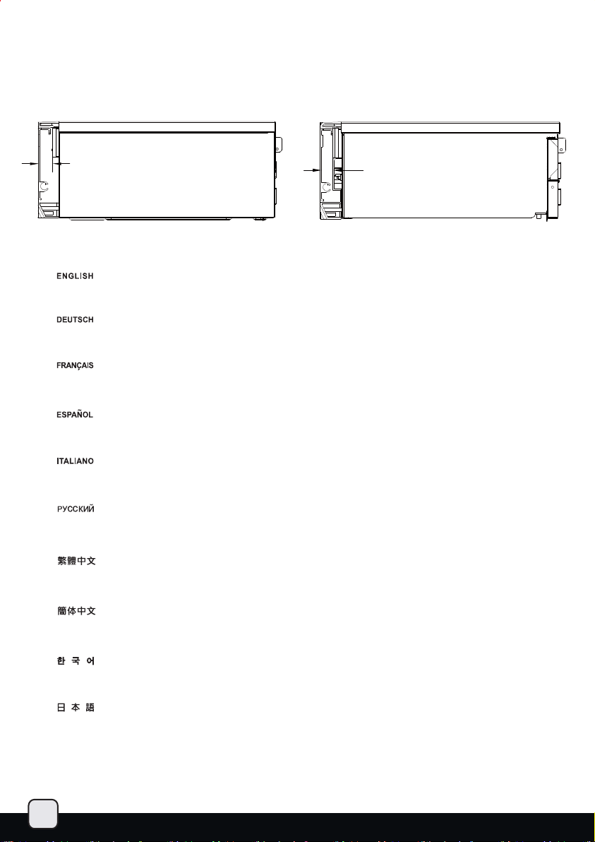
3
Loosen the screws holding the fan
filter to the fan to remove the fan filter.
Открутите шурупы, крепящие фильтр
к вентилятору, и выньте фильтр.
Lösen Sie die Schrauben, die den
Lüfterfilter am Lüfter halten, nehmen
Sie den Lüfterfilter ab.
Dévissez les vis fixant le filtre du
ventilateur pour le retirer.
Afloje los tornillos que sujetan el
filtro del ventilador al ventilador
para quitar el filtro.
Allentare le viti che tengono il filtro
della ventola per rimuoverlo.
4
To remove the power supply fan
filter, flip the case upside-down
then loosen the screws holding
the fan filter to remove it.
Zum Ausbau des Netzteillüfterfilters
stellen Sie das Gehäuse auf den Kopf,
lösen die Lüfterfilter-Halteschrauben
und nehmen den Lüfterfilter ab.
鬆開風扇背面,鬆開鎖固濾網的4顆螺絲,
就可以把濾網拆卸下。
松开风扇背面,松开锁固滤网的4颗螺丝,
就可以把滤网拆卸下。
ファンにファンフィルタを固定してい
るネジを外して、ファンフィルタを取
り外します。
팬 필터를 고정하고 있는 나사를 풀어
팬 필터를 제거합니다.
Чтобы снять фильтр вентилятора
блок а питания, переверните корпус,
открути те шурупы фильтра и выньте
его.
如果需要拆卸電源供應器的濾網,
請翻置機殼底部,鬆開鎖固電源供
應器濾網的螺絲。
Pour retirer le filtre du ventilateur
de l'alimentation, basculez le boîtier
à l'envers puis desserrez les vis
fixant le filtre pour le retirer.
Para quitar el filtro de la fuente de
alimentación, de la vuelta a la
carcasa y luego afloje los tornillos
que sujetan el filtro del ventilador
para quitarlo.
Per rimuovere il filtro della ventola
dell’alimentatore, girare il case sottosopra quindi allentare le viti che
tengono il filtro per rimuoverlo.
如果需要拆卸电源供应器的滤网,
请翻置机壳底部,松开锁固电源供
应器滤网的螺丝。
電源ファンフィルタを取り外すには、
ケースを逆さまにしてから、ファンフ
ィルタを固定しているネジを外してそ
れを取り外します。
파워 서플라이 팬필터 제거는 케이스를
뒤집은 후, 팬필터를 고정하고 있는
나사를 제거한 후 제거합니다.
28
Page 30

Dual purpose space
There is a dual purpose space located above the power supply area,
it can be used for either of the two following application:
A
B
Installation of a 3.5” hard drive Для установки 3,5-дюймового
Zur Installation einer 3,5-ZollFestplatte.
Installation d'un disque dur 3.5”.
Instalación de disco duro de 3,5”.
Installazione di un hard disk da 3,5”.
Installation of a slot device or short
expansion card such as extra
motherboard I/O, fan controller, or
daughter board (e.g. ASUS Xonar
HDAV1.3) plus one 2.5” hard drive.
Extra power supply rubber feet are
included for providing support to
expansion card installed above the
power supply.
Zur Installation eines Einschub-Gerätes
oder einer kurzen Erweiterungskarte
wie zusätzlicher Motherboard-I/O,
Lüftersteuerung oder Daughterboard
(z. B. ASUS Xonar HDAC1.3) plus
zusätzliche 2,5-Zoll-Festplatte. Spezielle
Gummifüße wird mitgeliefert, mit deren
Hilfe eine oberhalb des Netzteils
installierte Erweiterungskarte richtig sitzt.
жесткого диска.
安置一個3.5”硬碟。
安置一个3.5”硬盘。
3.5インチのハードドライブの
インストール。
3.5” 하드 드라이브 설치.
Для установки щелевого устройства
или короткой карты расширения,
например дополнительных входов/
выходов материнской платы, контроллера
вентилятора, дочерней платы (например,
ASUS Xonar HDAV1.3), плюс одного 2,5дюймового жесткого диска. Для установки
карты расширения над блоком питания
прилагаются дополнительные резиновые
ножки.
安置一個
Slot device(通常是Slot I/O,
風扇調速模組,或是ASUS Xonar HDAV1.3
音效子卡)+一個2.5”硬碟(如果您安置子
卡裝置,我們建議您可以把電源供應器腳
墊黏在電源供應器上面,以適度支撐子卡
的電路板)。
29
Installation d'une carte d'extension ou
d'une équerre additionnelle comme
des ports E/S de carte mère, contrôleur
de ventilateur, ou une carte fille (par
exemple: ASUS Xonar HDAV1.3) avec
en plus un disque dur 2.5”. Des pieds
supplémentaires en caoutchouc sont
inclus pour l'alimentation afin de fournir
un support à la carte d'extension situé
au dessus de l'alimentation.
Instalación de un dispositivo o tarjeta
de expansión pequeños como una E/S
extra para placa base, controlador de
ventilador ó daughter board (e.g. ASUS
Xonar HDAV1.3) mas un disco duro de
2,5”. Se incluyen pies de goma adicionales
para la fuente de alimentación para
proporcionar un apoyo a la tarjeta de
expansión instalable sobre la fuente de
alimentación.
Installazione di una qualsiasi periferica
slot, od una piccola periferica di
espansione come un pannello con
connessioni extra I/O, un fan controller,
una daughter board ( Es. ASUS XONAR
HDAV1.3) più un hard disk da 2,5”.
Piedini in gomma per l’alimentatore
aggiuntivi, per fornire supporto alla
scheda di espansione installata, sono
in dotazione.
安置一个Slot device(通常是Slot I/O,
风扇调速模块,或是ASUS Xonar HDAV1.3
音效子卡)+一个2.5”硬盘(如果您安置子
卡装置,我们建议您可以把电源供应器脚
垫黏在电源供应器上面,以适度支撑子卡
的电路板)。
スロットデバイスまたは特別なマザー
ボードI/O、ファンコントローラ、ま
たはドータボード(例:ASUS Xonar
HDAV1.3)、さらに2.5インチハードドラ
イブ1台など、短めの拡張カードのイン
ストール。電源の上でインストールされ
た拡張カードを支持するよう、特製電源
ゴムフットが付属しています。
슬롯 장치의 설치 즉, 추가 메인보드
I/O, 팬 컨트롤러, 도터보드( 예 ASUS
Xonar HDAV1.3) 혹은 2.5” 하드 드라이브.
파워 서플라이 상부에 추가로 확장카드를
설치 할 경우 이를 지지하기 위해 추가로
파워서플라이 고무발이 동봉되어 있습니다.
Page 31

Expansion card removal guide
Although GD06’s interior space is designed tightly, you can still install expansion
cards without having to remove other brackets. Please refer to the following
scenarios: (with the top cover already removed)
A
1
If the rear hard drive’s cables are blocking the left expansion card, please first unplug the hard drive cables then proceed to
remove/install the expansion card. Make sure to plug the cables back into the hard drive after installation.
Falls die Kabel der hinteren Festplatte die linke Erweiterungskarte blockieren, ziehen Sie zunächst die Festplattenkabel ab und
installieren/deinstallieren anschließend die Erweiterungskarte. Vergessen Sie nicht, die Kabel anschließend wieder an die Festplatte
anzuschließen.
Si les câbles arrières des disques durs bloquent la cartes d'extension de gauche, veuillez d'abord débrancher les câbles des disques
durs puis retirez/installez la carte d'extension. N'oubliez pas de rebrancher les câbles à vos disques durs après l'installation.
Si los cables del disco duro trasero bloquean la tarjeta de expansión izquierda, por favor desconecte primero los cables del disco
duro y luego proceda a retirar/instalar la tarjeta de expansión. Asegúrese de volver a conectar los cables en el disco duro tras la i
nstalación.
Se i cavi posteriori dell’alimentatore bloccano la scheda di espansione di sinistra, per prima cosa rimuovere i cavi dell’hard disk
quindi procedere con la rimozione/installazione della scheda di espansione avendo cura di ricollegare i cavi rimossi al termine
della procedura.
Если кабели заднего жесткого диска блокируют левую карту расширения, сначала отсоедините кабели, а потом приступайте
к демонтажу/установке карты расширения. Не забудьте в конце установки снова подключить кабели жесткого диска.
如果後方硬碟的排線檔著左側的介面卡,請先暫時移除排線。待介面卡移除/安裝完畢,再插回排線。
如果后方硬盘的排线文件着左侧的适配卡,请先暂时移除排线。待适配卡移除/安装完毕,再插回排线。
後部ハードドライブのケーブルが左の拡張カードを邪魔しているならば、まずハードドライブケーブルのプラグを抜きます。
それから、拡張カードの取り外し/インストールを続行してください。インストール後は、ケーブルをハードドライブに再度
接続することをお忘れなく。。
2
오른쪽 확장카드가 왼쪽의 카드에의해 막혀 을 경우, 왼쪽 카드를 먼저 제거 한후, 오른쪽 카드를 설치하거나 제거하면 중앙
버팀대를 제거 하지 않고도 가능합니다.
30
Page 32
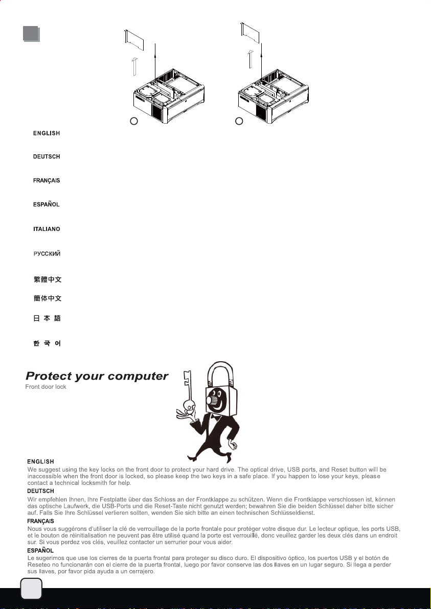
B
1
If the expansion card on the right side is blocked by the card to the left, please first remove the card on the left side to allow the
card on the right side to be removed without taking the center brace off the case.
Falls die Erweiterungskarte auf der rechten Seite von der linken Karte blockiert wird, nehmen Sie zunächst die Karte auf der linken
Seite heraus – so können Sie die rechte Karte entfernen, ohne die mittlere Halterung aus dem Gehäuse ausbauen zu müssen.
Si la carte d'extension sur le côté droit est bloqué par celle de gauche, veuillez d'abord la carte du côté gauche pour permettre à la
carte du côté droite d'être retiré sans avoir à démonter la barre centrale du boîtier.
Si la tarjeta de expansión del lado derecho está bloqueada por la tarjeta de la izquierda, por favor retire la tarjeta de la izquierda
para permitir que la tarjeta del lado derecho pueda ser retirada sin quitar el eje central de la carcasa.
Se la scheda di espansione nella parte destra è bloccata dalla scheda di sinistra, per prima cosa rimuovere la scheda di sinistra per
permettere la rimozione di quella di destra senza spostare il gancio centre.
Если правая карта расширения блокируется левой, то сначала удалите карту слева, чтобы можно было снять правую
карту без вытаскивания из корпуса центральной скобы.
如果最右側的介面卡緊鄰左側有介面卡,請先暫時移除左側的介面卡,讓最右側的介面卡可以閃避中支架移出。
如果最右侧的适配卡紧邻左侧有适配卡,请先暂时移除左侧的适配卡,让最右侧的适配卡可以闪避中支架移出。
右側の拡張カードが左側のカードによって邪魔されているならば、右側のカードがケースから中央の支柱をとらずに取り外せるよう、
まず左側のカードを取り外してください。
오른쪽 확장카드가 왼쪽의 카드에의해 막혀 을 경우, 왼쪽 카드를 먼저 제거 한후, 오른쪽 카드를 설치하거나 제거하면 중앙 버팀대를
않고도 가능합니다.
제거 하지
2
31
Page 33

Page 34
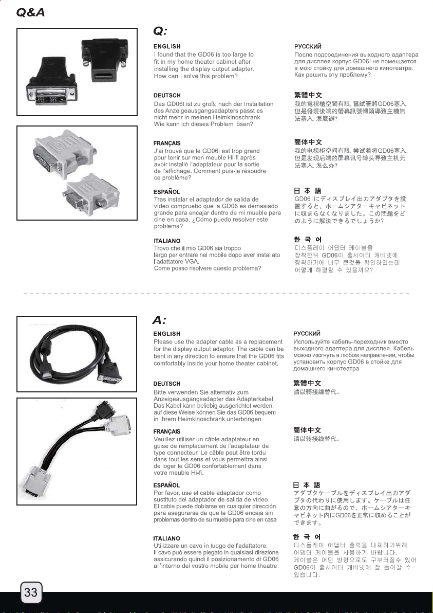
Page 35

Page 36
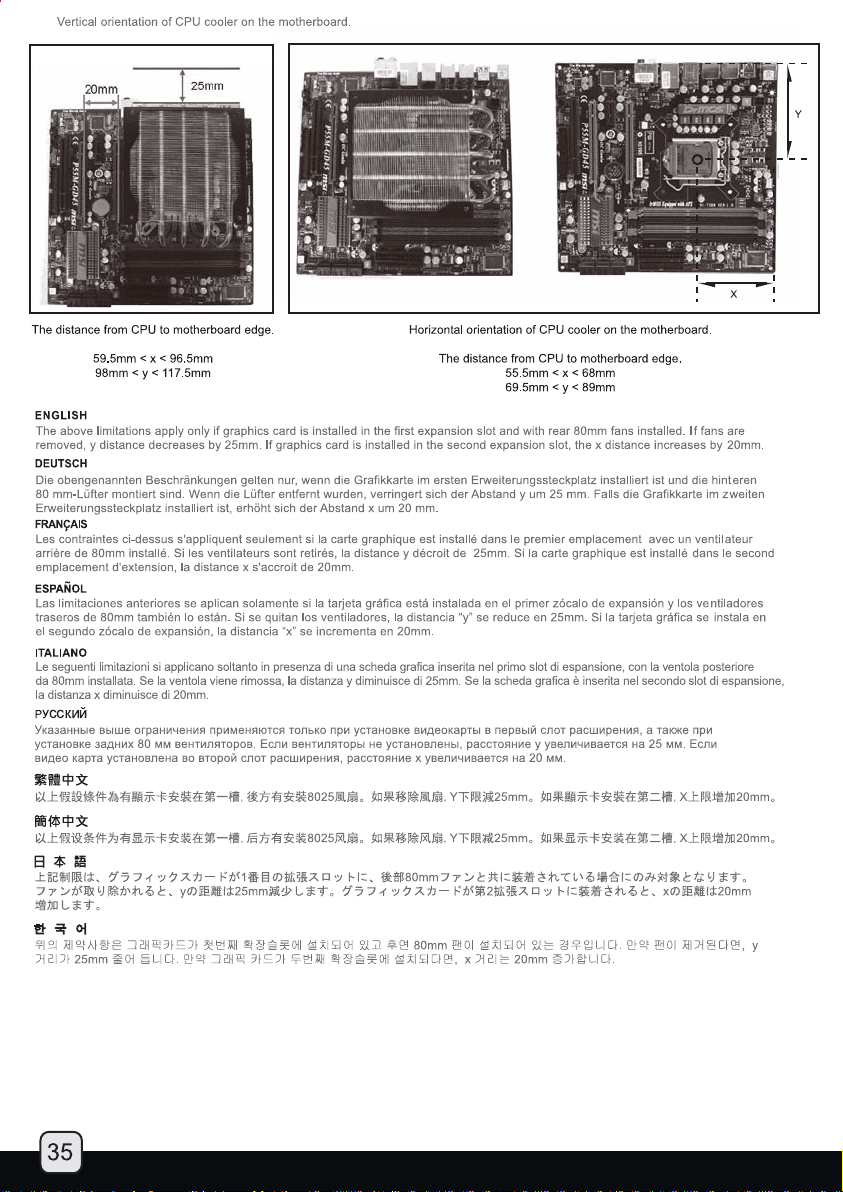
Page 37
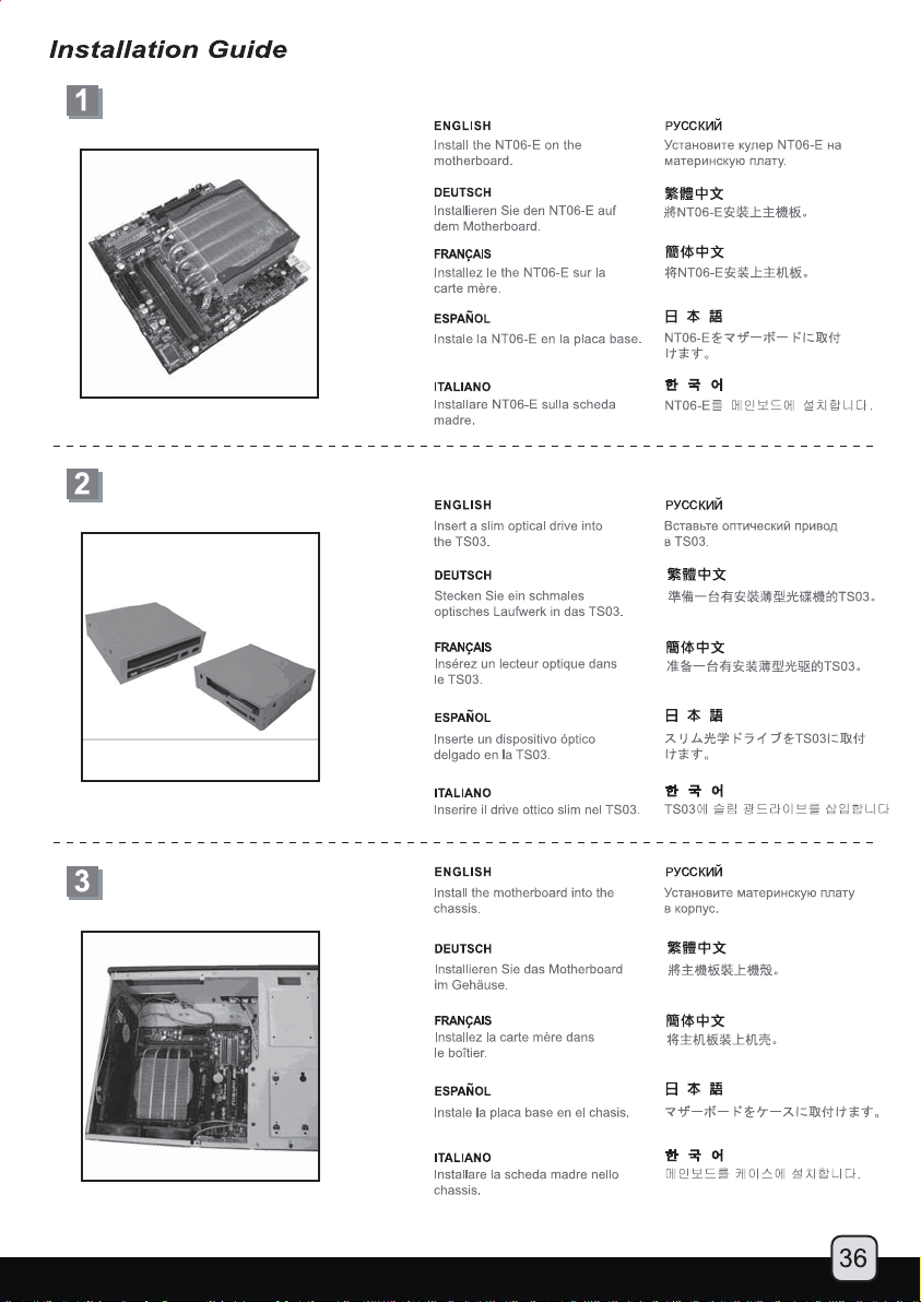
Page 38
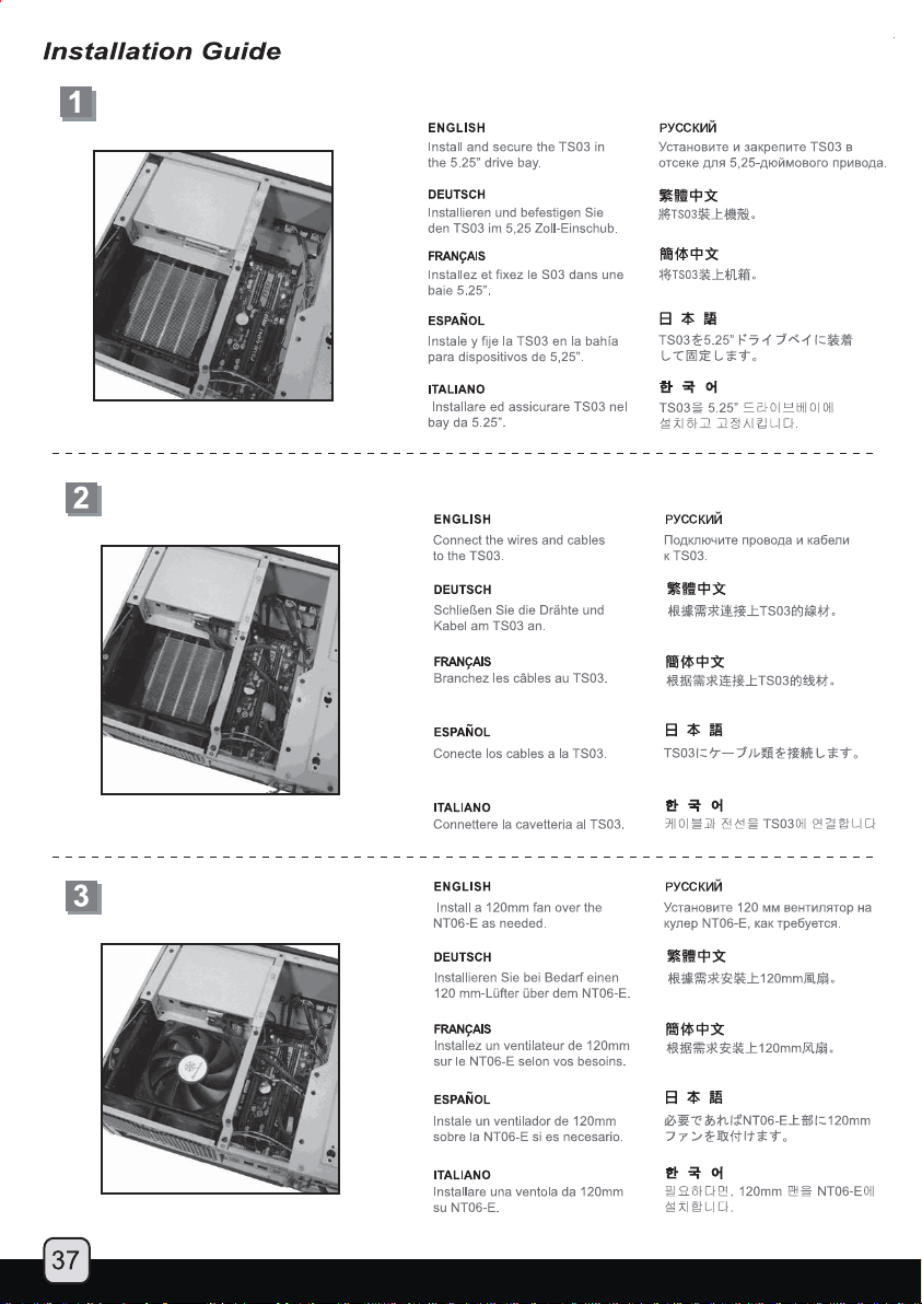
Page 39

 Loading...