

Page 1
FORTRESS SERIES
FT04
MANUAL
Page 2

Installation and system optimization guide:
n
The following manual and guides were carefully prepared by the SilverStone engineering team to help
you maximize the potential of your SilverStone product. Please keep this manual for future reference
when upgrading or performing maintenance on your system. A copy of this manual can also be
downloaded from our website at:
http://www.silverstonetek.com
k.com
Specification
ificatio
Disassemble chart
Installation guide
Connector definition
Front I/O connector guide
P.2
P.3
P.5
P.17
P.19
Component size limitations
CPU and graphic card supporter
Optimal Thermal Performance Layout
Upgrade And Maintenance
Protect Your Computer
Q & A
P.20
P.25
P.27
P.31
P.38
P.39
1
Page 3
FORTRESS SERIES
FT04
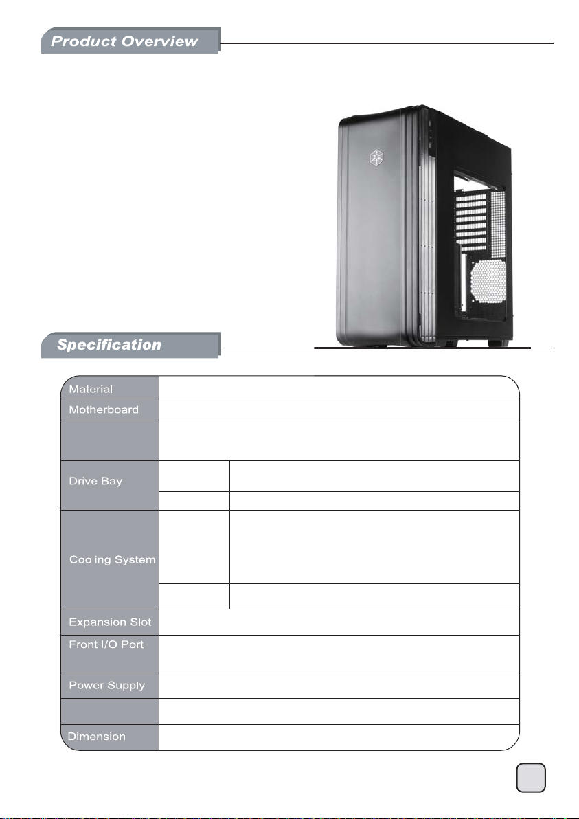
Setting the thermodynamic benchmark
Aluminum door and top panel, steel body
SSI-EEB, SSI-CEB, Extended ATX, ATX, Micro-ATX
Model No.
SST-FT04B-W (black + window)
SST-FT04S-W (silver + window)
Exposed
Internal
5.25" x 2
3.5“ x 1 (transfer bracket,未定案)
3.5" x 7 (2 hot-swap) , 2.5” x 4
Expansion Card
Front
USB 3.0 x 2 (backward compatible with USB 2.0)
audio x 1
MIC x 1
1 x Optional standard PS2 (ATX) no length limitation
Compatible up to 13.3” long, width restriction-6.69”*
219mm (W) x 546mm (H) x 482mm (D), 57.6 liters
2 x AP182 180mm intake fan 500~2000rpm, 17~42 dBA
(compatible with 3 x 120mm fan)
Aluminum side panel heat conductionRear
8
2
Page 4
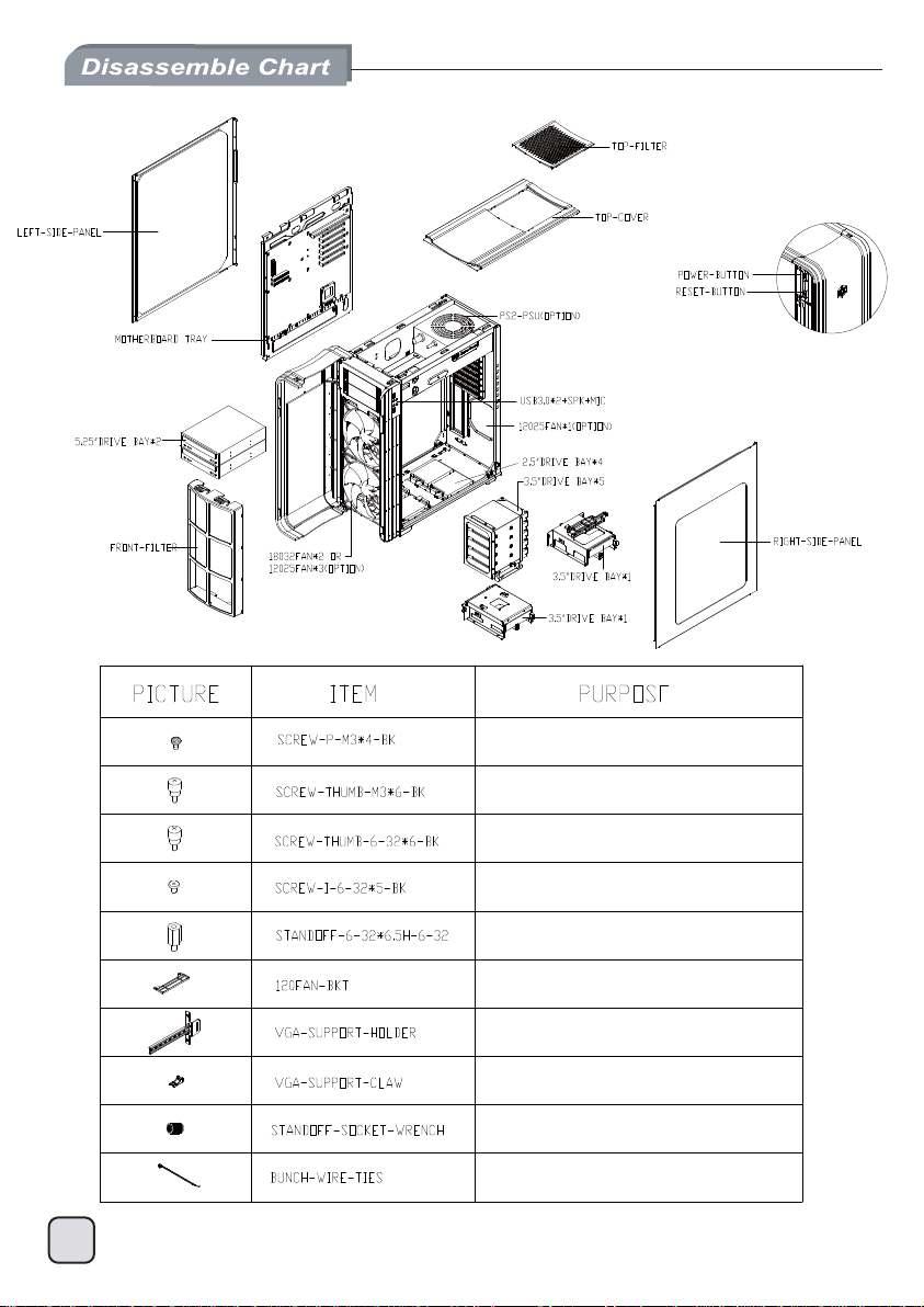
Secure 2.5” HDD
Secure optical drives
Secure VGA holder and claw
Secure PSU, 12025 fan, motherboard and 3.5” HDD
Motherboard standoff
Secure 12025 fan
VGA supporter holder
VGA supporter claw
Standoff screw
Cable management
3
Page 5
4
Page 6
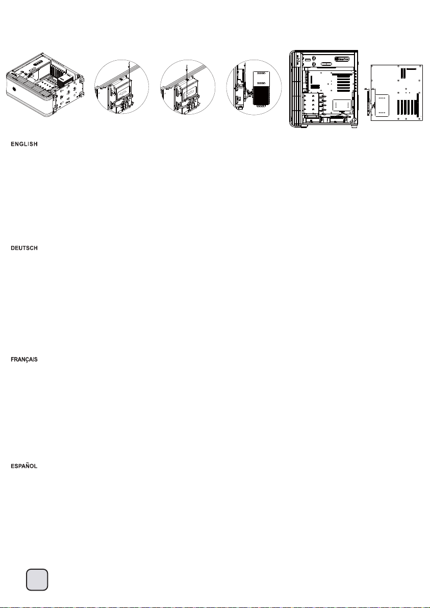
lnstallation Guide
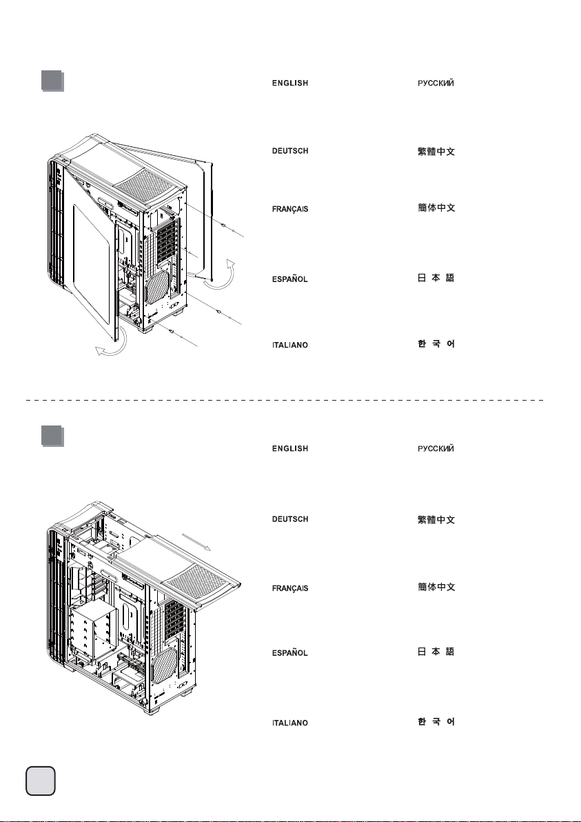
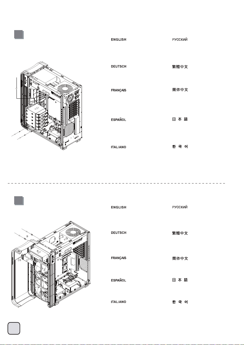
1
Loosen two screws from both left
and right side panels to remove
them.
Lösen Sie die beiden Schrauben
an den linken und rechten
Seitenwänden, nehmen Sie die
Seitenwände ab.
Desserrez les vis des deux panneaux
latéraux pour les retirer.
Desatornille dos tornillos de los paneles
izquierdo y derecho para quitarlos.
Per rimuovere i pannelli laterali
allentare, per entrambi, le due
viti di serraggio.
Отвинтите по два винта, крепящих
левую и правую боковых панели,
и снимите панели.
取下左右側板各兩顆螺絲,卸下側板。
取下左右侧板各两颗螺丝,卸下侧板。
両方の左右パネルからネジ2本を緩めて、
取り外します。
왼쪽과 오른쪽 사이드 패널에서 두
개씩 나사를 풀어 사이드 패널을
제거합니다.
2
Remove top panel by pushing it
toward the rear.
Снимите верхнюю панель,
переместив ее назад.
.
Entfernen Sie die obere Blende,
indem Sie sie nach hinten
drücken.
Retirez le panneau supérieur en le
poussant vers l'arrière.
Retire el panel superior tirando de él
hacia la parte posterior.
Rimuovere il pannello superiore
spingendolo verso la parte
posteriore.
將上蓋往後推,取下上蓋。
将上盖往后推,取下上盖。
上部パネルを後方に押して取り外
します。
뒤쪽으로 밀어 상단 패널을
분리하십시오.
5
Page 7
lnstallation Guide
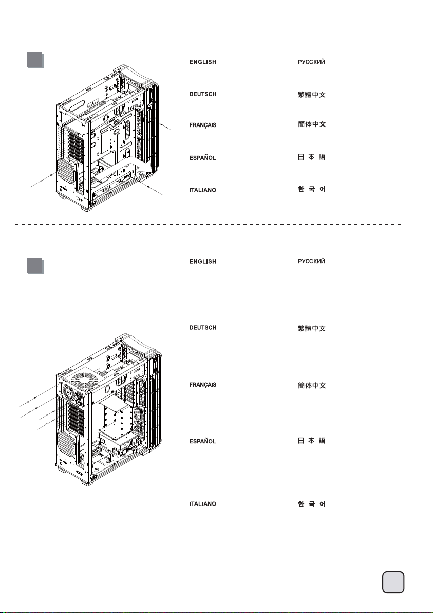
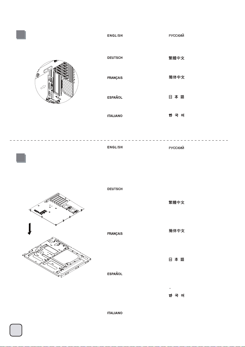
3
Loosen three screws holding the
motherboard tray to remove it.
Lösen Sie die drei Schrauben, welche
die Motherboard- Halterung fixieren,
nehmen Sie die Halterung ab.
Desserrez les trois vis tenant le plateau
de la carte mère pour le démonter.
Desatornille tres tornillos que sujetan
la bandeja de la placa base para
quitarla.
Per rimuovere il supporto scheda madre
allentare le tre viti di serraggio.
4
Insert the power supply from the top,
if the power supply has a build-in
120mm fan or larger, we recommend
installing the power supply with its
fan facing up.
Setzen Sie das Netzteil von oben ein;
sofern das Netzteil über einen
120 mm-Lüfter (oder größer) verfügt,
empfehlen wir, das Netzteil mit dem
Lüfter nach oben einzubauen.
Отвинтите три винта, крепящих
кронштейн материнской платы,
и снимите его.
取下主機板托盤3顆螺絲,將主機板托盤抽出。
取下主机板托盘3颗螺丝,将主机板托盘抽出。
マザーボードトレイを固定しているネジ3本を
緩めて、取り外します。
3개의 나사를 풀어 메인보드 트레이를
제거합니다.
Установите блок питания в верхней части
корпуса. Если блок питания оснащен
встроенным вентилятором размером
120 мм или больше, рекомендуется
устанавливать блок питания вентилятором
вверх.
將電源供應器由上放入機殼內,如果有12公分
或以上尺寸的風扇建議朝上放置。
Insérez l'alimentation par le dessus,
si l'alimentation possède un ventilateur
intégré de 120mm ou plus, nous vous
recommandons de l'installer avec le
ventilateur orienté jusqu'à.
Inserte la fuente de alimentación desde
arriba, si la fuente de alimentación tiene
un ventilador de 120mm ó más grande
incluido, le recomendamos que instale
la fuente de alimentación con su ventilador
hacia hasta.
Inserire l’alimentatore dalla parte
superiore, se lo stesso possiede una
ventola da 120mm o più grande, vi
raccomandiamo di installarlo con la
ventola in cima.
将电源供应器由上放入机壳内,如果有12公分
或以上尺寸的风扇建议朝上放置。
上部から電源を入れます。電源が内蔵で
120mmまたはより大きなファンを備えている
場合は、ファンが上向きになるよう電源を取
り付けるようお勧めします。
파워 서플라이를 위에서부터삽입합니다.
만약 파워서플라이에 120mm 이상의
팬이장착되어 잇는 경우 파워서플라이의
팬이 최대쪽을향하도록 설치합니다.
6
Page 8
lnstallation Guide
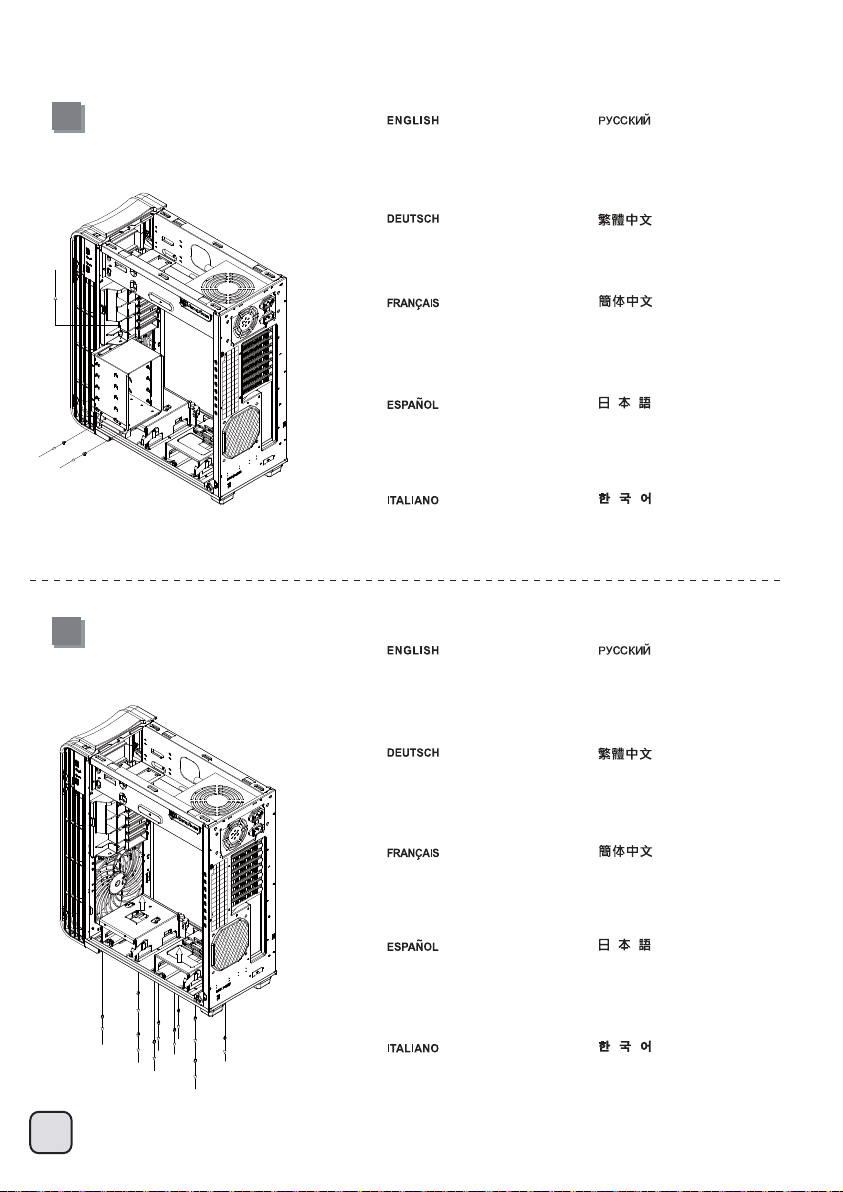
5
Remove 3.5” drive cage. Извлеките кронштейн для
Nehmen Sie die 3,5
Zoll-Laufwerkhalterung heraus.
Retirez le casier des lecteurs 3.5”.
Quite la carcasa para dispositivos
de 3,5”
Rimuovere il supporto hard
drive da 3,5”
3,5-дюймовых жестких дисков.
移除3.5”主硬碟架。
移除3.5”主硬盘架。
3.5インチドライブケージを取り外します。
3.5” 드라이브 케이지를 제거합니다.
6
Loosen the screws holding the
lower drive cage to remove it.
Отверните винты крепления
нижнего отсека для жестких
.
дисков и извлеките его.
Lösen Sie die Schrauben, welche
den unteren Festplattenkäfig fixieren,
nehmen Sie den Käfig ab.
Dévissez les vis pour l'enlever en tenant
la cage du lecteur inférieur pour le retirer.
Afloje los tornillos sujetando la carcasa
para discos inferior para retirarla.
Allentare le viti che fissano il cage
unità inferiore per rimuoverlo.
拆除底部硬碟架螺絲,取下硬碟架。
拆除底部硬盘架螺丝,取下硬盘架。
下部ドライブケージを保持している
ネジをゆるめて取り外します。
하단 드라이브 케이지를 고정하는
나사를 풀어 케이지를 분리하십시오.
7
Page 9
lnstallation Guide
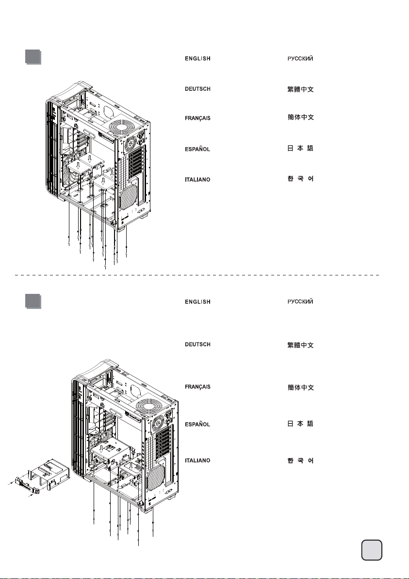
7
Install 2.5” drive into the bottom of
the chassis and secure with screws.
Installieren Sie das 2,5 Zoll-Laufwerk
im unteren Teil des Gehäuses;
anschließend mit Schrauben fixieren.
Installez le lecteur 2.5” dans le bas du
boîtier et fixez-le avec des vis.
Instale el disco de 2,5” en la parte inferior
de la carcasa y fíjelo con tornillos.
Installare il drive da 2,5” nella parte bassa
dello chassis ed assicurarlo alla struttura
con le viti in dotazione.
8
Reinstall the lower drive cage. If you
want to utilize CP05, you can install
it now.
Установите 2,5-дюймовый жесткий диск в
нижнюю часть корпуса и закрепите его
винтами.
將2.5”硬碟裝入機殼底部,並鎖上螺絲。
将2.5”硬盘装入机壳底部,并锁上螺丝。
ケース底部に2.5インチドライブを装着し、
ネジで固定します。
2.5”드라이브를 케이스 바닥에 장착한 후
나사로 고정합니다.
Установите на место нижний отсек для
жестких дисков. Если вы хотите
использовать CP05, вы можете
установить его прямо сейчас.
Bringen Sie den unteren
Festplattenkäfig wieder an. Wenn
Sie den CP05 nutzen möchten,
können Sie ihn jetzt installieren.
Réinstallez la cage de lecteur inférieur.
Si vous voulez utiliser le CP05, vous
pouvez l'installer maintenant.
Reinstale la carcasa para discos inferior.
Si desea instalar la CP05, lo puede
hacer ahora.
Installare di nuovo la gabbia unità
inferiore. Se si vuole usare CP05, è
possibile installarlo adesso.
將底部硬碟架裝回,如果有需要安裝CP05,
可在這時安裝。
将底部硬盘架装回,如果有需要安装CP05,
可在这时安装。
下部ドライブケージを再び取り付けます。
CP05の利用を希望する場合、
今取り付けることができます。
하단 드라이브 케이지를 다시 설치합니다.
CP05를 활용하려면 지금 이를 설치할
수 있습니다.
8
Page 10
lnstallation Guide
10
9
9
Install motherboard rear I/O plate
into the chassis.
Installieren Sie das hintere
I/O-Blech im Gehäuse.
Installez la plaque arrière de la carte
mère dans le boîtier.
Instale la placa trasera de E/S de la
placa base en la carcasa.
Installare la placca I/O della scheda
madre nella sede preposta.
Install motherboard onto the
motherboard tray. If you have
already installed a large CPU cooler
on the motherboard, we recommend
connecting ATX12V 4pin or EPS 8pin
cables from your power supply to the
motherboard now to make installation
easier later on.
Installieren Sie das Motherboard
auf der Motherboard-Halterung.
Sofern Sie bereits einen großen
CPU-Kühler auf dem Motherboard
installiert haben, empfehlen wir, die
4-poligen ATX12V- oder 8-poligen
EPS-Kabel vom Netzteil jetzt an das
Motherboard anzuschließen; dies
erleichtert die weitere Installation.
Installez la carte mère sur son support.
Si vous avez déjà installé un dissipateur
de processeur de grande taille sur la carte
mère, nous vous recommandons de
brancher tout de suite les câbles ATX12V
4pin ou EPS 8pin de votre alimentation à
sur votre carte mère pour rendre
l'installation plus facile plus tard.
Instale la placa base en la bandeja de la
placa base. Si ya tiene instalado un
disipador grande de CPU en la placa
base, le recomendamos que conecte los
cables ATX12V 4 pines ó EPS 8 pines
de su fuente de alimentación a la placa
base ahora para que la instalación sea
más fácil después.
Installare la scheda madre sul supporto.
Se avete già montato un dissipatore per
CPU di grandi dimensioni, vi consigliamo
di collegare i connettori dei cavi ATX12V
4pin o EPS 8pin dell’alimentatore subito,
per renderne più semplice la connessione.
Установите в корпус заднюю панель
ввода-вывода материнской платы.
將I/O彈片裝上機殼。
将I/O弹片装上机壳。
ケース内にマザーボード後部
I/Oプレートをインストールします。
메인보드 후방 I/O 판을 케이스에
장착합니다.
Установите материнскую плату на
кронштейн материнской платы. Если
на материнскую плату уже установлен
процессорный кулер большого
размера, на данном этапе
рекомендуется подсоединить к
.
материнской плате 4-контактный
разъем кабеля ATX 12 В или
8-контактный разъем кабеля EPS от
блока питания для упрощения
дальнейшего процесса установки.
將主機板安裝於主機板托盤,如果
您已經裝上大型CPU散熱器,我們建
議您先在機殼外把ATX 4Pin / EPS 8pin
插上電源線。如果電源線夠長或為
模組化電源線,安裝步驟將更為順利。
将主机板安装于主机板托盘,如果
您已经装上大型CPU散热器,我们建
议您先在机壳外把ATX 4Pin / EPS 8pin
插上电源线。如果电源线够长或为
模块化电源线,安装步骤将更为顺利。
マザーボードトレイ上にマザーボード
を取り付けます。マザーボードに大型
CPUクーラーがインストール済みならば、
あとのインストールが容易に行える
よう、電源からATX12V 4ピンまたはEPS
8ピンケーブルをマザーボードにこの時
点で接続しておくようにお勧めします。
메인보드를 메인보드 트레이에
설치합니다. 메인보드에 커다란
CPU쿨러를 설치한 경우, ATX12V
4핀이나 EPS 8핀 케이블을 파워
서플라이에서 메인보드로 미리
연결하여, 나중의 설치를 편하게
합니다.
Page 11
lnstallation Guide
11
Reinstall the assembled motherboard
tray back into the chassis. If you have
either the ATX12V 4pin or EPS 8pin
cables connected, please make sure
to have it pass through the opening
between power supply and the
motherboard compartment.
Setzen Sie die Motherboard-Halterung
nebst Motherboard wieder in das
Gehäuse ein. Sofern Sie das 4-polige
ATX12V- oder das 8-polige EPS-Kabel
bereits angeschlossen haben, achten
Sie darauf, dass das Kabel durch die
Öffnung zwischen Netzteil und
Motherboard verläuft.
Remettez la carte mère assemblé à son
support dans le boîtier. Si vous avez soit
le câble ATX12V 4pin soit le câble EPS
8pin déjà branché, veuillez bien vérifier
de l'avoir passé par l'ouverture entre
l'alimentation et le compartiment de la
carte mère.
Reinstale la bandeja de la placa base
montada de nuevo en el chasis. Si tiene
instalado el cable ATX12V 4 pines ó EPS
8 pines, asegúrese por favor de haberlos
pasado a través de la abertura entre la
fuente de alimentación y el compartimento
de la placa base.
Установите кронштейн с материнской
платой в сборе в корпус. Если был
подключен 4-контактный разъем кабеля
ATX 12 В или 8-контактный разъем
кабеля EPS, кабель необходимо проложить
через отверстие между блоком питания и
отсеком для материнской платы.
將主機板托盤裝回機殼,如果已經接上
ATX 4pin / EPS 8Pin線材,請注意線材通過
下方的缺口。
将主机板托盘装回机壳,如果已经接上
ATX 4pin / EPS 8Pin线材,请注意线材通过
下方的缺口。
組み上げたマザーボードトレイをケースに戻し
ます。ATX12V 4ピンまたはEPS 8ピンケーブル
のいずれかが接続されているならば、ケーブル
が電源とマザーボードコンパートメントの間の開
口部を通っていることを確かめてください
Reinstallare la scheda madre ed il
supporto nel cabinet. Se avete collegato
anche i connettori dei cavi ATX12V 4pin o
EPS 8pin, assicuratevi di averli fatti
passare nell’apertura posta tra
l’alimentatore ed il compartimento della
scheda madre.
조립된 메인보드 트레이를 케이스에 재
설치합니다. 만약 ATX12V 4핀이나 EPS 8핀
케이블이 연결되어 있다면, 파워 서플라이와
메인보드 쪽 빈공간을 케이블이 지나가도록
합니다.
10
Page 12
lnstallation Guide
12
We recommend that you start cable
manage now and connect cables
such as the ATX 24pin, front I/O
connectors, and any other connectors
from front panel devices.
Wir empfehlen, jetzt mit dem Verlegen
der Kabel zu beginnen und die
24-poligen ATX-, Front-I/O- und
sämtliche weiteren Kabel von
Geräten an der Frontblende
anzuschließen.
Nous vous recommandons de
commencer à gérer l'organisation des
câbles maintenant comment l'ATX 24pin,
les connecteurs des ports E/S de façade,
et tout autre connecteur des appareils du
panneau frontal.
Le recomendamos que empiece a
gestionar el enrutado de cables ahora
y conecte cables como el ATX 24 pines,
los conectores frontales E/S y cualquier
otro conector de los dispositivos del
panel frontal.
Vi raccomandiamo di iniziare subito
la sistemazione delle connessioni e
collegare quindi i connettori relativi
ai cavi ATX 24pin, alle connessioni
I/O frontali e qualsiasi altro
collegamento delle periferiche poste
frontalmente.
На этом этапе рекомендуется начать
прокладку кабелей и подсоединить
кабели, например кабель ATX с
24-контактным разъемом, разъемы
ввода-вывода передней панели и любые
другие разъемы от устройств на
передней панели.
我們建議您可以在此時開始理線,請先安
上ATX24Pin接線,Front panel controller
與Front I/O。
我们建议您可以在此时开始理线,请先安
上ATX24Pin接线,Front panel controller
与Front I/O。
この時点でケーブル取り回しを考えながら、
ATX 24ピン、フロントI/Oコネクタ、その他フ
ロントパネルデバイスからのコネクタ類のケ
ーブルを接続するようお勧めします。
이 단계에서부터 ATX 24핀, 전면 I/O
커넥터, 그리고 전면 패널에서의 다른
커넥터 등 케이블 정리를 하시기를
권장합니다.
11
Page 13
lnstallation Guide
13
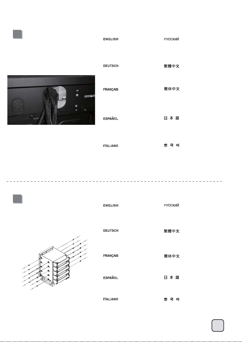
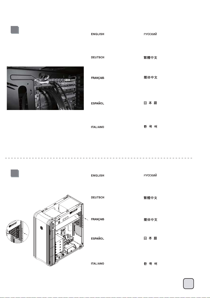
Route all power supply cables to the
opening on the left of the power
supply.
Проложите все кабели питания через
отверстие слева от блока питания.
14
Verlegen Sie sämtliche Netzteilkabel
durch die Öffnung links vom Netzteil.
Faîtes passer tous les câbles de
l'alimentation par l'ouverture situé à
sa gauche.
Enrute todos los cables de la fuente de
alimentación por la abertura a la
izquierda de la fuente de alimentación.
Convogliare tutti i cavi dell’alimentatore
verso l’apertura alla sinistra
dell’alimentatore stesso.
Install 3.5” hard drives into the
drive cage.
Bauen Sie 3,5-Zoll-Festplatten in
die Laufwerkhalterung ein.
請將所有電源線穿過電源左邊的開孔。
请将所有电源线穿过电源左边的开孔。
全ての電源ケーブルを電源の左上の
開口部に通します。
모든 파워서플라이 케이블을 파워서플라이의
왼쪽 빈 공간에 정리해줍니다.
Установите 3,5-дюймовые жесткие диски в
кронштейн для жестких дисков.
將3.5”硬碟安裝至主硬碟架。
Installez les disques durs 3.5” dans
le casier.
Instale discos duros de 3,5” en la
carcasa para dispositivos
Installare gli hard drive da 3,5” nel
supporto.
将3.5”硬盘安装至主硬盘架。
ドライブケージに3.5インチハードドライブを装
着します。
3.5” 하드 드라이브를 드라이브 케이지에
설치합니다.
12
Page 14
lnstallation Guide
15
Install hard drive cage back into the
case with cables routed.
1Установите кронштейн для жестких
дисков на место в корпус с
проложенными кабелями.
16
Bauen Sie die Laufwerkhalterung
wieder das Gehäuse ein. Achten
Sie darauf, die Kabel sauber zu
verlegen.
Remettez le casier dans le boîtier avec
faisant cheminer correctement les
câbles.
Instale de nuevo la carcasa para discos
duros en la carcasa con los cables
enrutados.
Riposizionare il supporto nel case con i
cavi opportunamente sistemati.
Remove the 5.25” drive bay covers
to install required 5.25” devices.
Dem Sie die Abdeckung der
5,25-Zoll-Laufwerkschächte ab,
installieren Sie die gewünschten
5,25-Zoll-Geräte.
將3.5”主硬碟架裝回機殼,
同時請注意理線。
将3.5”主硬盘架装回机壳,
同时请注意理线。
ケーブルを取り回しながら、ハードドラ
イブケージを元に戻します。
하드 드라이브 케이지를 케이스에
넣은 후 케이블을 정리합니다.
Снимите крыши отсеков для
5,25-дюймовых устройств и
установите необходимые
5,25-дюймовые устройства.
移除5.25”檔板,安裝上5.25”裝置。
13
Retirez les caches des baies 5.25” pour
installer vos appareils.
Quite las cubiertas para bahía de
dispositivos de 5,25” para instalar los
dispositivos de 5,25” necesarios.
Per installare le necessarie periferiche da
5,25”, rimuovere il cover del bay da 5,25”
移除5.25”文件板,安装上5.25”装置。
5.25インチドライブベイカバーを外して、
必要な5.25インチデバイスを装着します。
5.25”드라이브 베이 커버를 제거한
후 필요한 5.25” 장치를 설치합니다.
Page 15
lnstallation Guide
17
Connect all cables for 5.25”, 3.5”,
and 2.5” drives as needed.
Подсоедините все кабели 5,25-дюймовых,
3,5-дюймовых и 2,5-дюймовых устройств
соответствующим образом.
18
Schließen Sie sämtliche Kabel für
verwendete 5,25-, 3,5- und
2,5-Zoll-Laufwerke an.
Branchez tous les câbles pour les
lecteurs 5.25”, 3.5”, et 2.5” selon
vos besoins
Conecte todos los cables necesarios
para dispositivos de 5,25”, 3,5” y 2,5”
Connettere tutti i cavi necessari per i
drive da 5,25”, 3,5” e 2,5”
Remove expansion slot covers to
install required expansion cards.
Unused slots should have covers
installed.
Entfernen Sie Steckplatzabdeckungen,
installieren Sie die gewünschten
Erweiterungskarten. Bei nicht
verwendeten Steckplätzen sollten
die Abdeckungen angebracht bleiben.
Retirez les équerres pour installer vos
cartes d'extension. Les emplacements
inutilisés doivent garder leur équerre.
先連接上所有磁碟需要用到的線材
(包含5.25”、3.5”以及 2.5”)
先连接上所有磁盘需要用到的线材
(包含5.25”、3.5”以及 2.5”)
必要に応じて5.25インチ、3.5インチ、および2.5
インチのドライブ用のケーブル全部を接続。
5.25”, 3.5”, 2.5” 드라이브 의 모든
케이블을 필요한 만큼 연결한 후
Снимите крышки слотов расширения для
установки необходимых плат расширения.
На неиспользуемые слоты следует
установить крышки.
移除擴充槽檔片並安裝擴充卡,未使用的擴充
槽請將檔片裝回並以內附螺絲鎖固。
移除扩充槽档片并安装扩充卡,未使用的扩充
槽请将档片装回并以内附螺丝锁固。
Quite las cubiertas de los zócalos de
expansión para instalar las tarjetas de
expansión necesarias. Los zócalos no
usados deberían tener cubiertas
instaladas.
Rimuovere i cover degli slot di espansione
per installare le schede. Gli slot inusati
dovrebbero conservare i cover.
拡張スロットカバーを取り外して、必要な拡張カ
ードを装着します。未使用のスロットにはカバー
を取り付けたままにします。
확장슬롯 커버를 제거한 후, 필요한
확장카드를 설치 합니다. 사용되지 않은
슬롯의 슬롯 커버는 다시 설치 합니다.
14
Page 16

lnstallation Guide
19
Insert 3.5” hard drive into the lower
hard drive cage
Установите 3,5-дюймовый жесткий
диск в нижний отсек для жестких
дисков
20
Setzen Sie eine 3,5-Zoll-Festplatte
in den unteren Festplattenkäfig ein
Insérez le lecteur 3,5" dans la cage
du lecteur inférieur
Inserte el disco duro de 3,5” en la
carcasa inferior para discos duros.
Inserire il disco rigido 3.5” nel cage
unità inferiore.
Reinstall the top panel.
Bauen Sie die obere Abdeckung
wieder ein.
額外的3.5”硬碟,請安裝於底部
硬碟架。
额外的3.5”硬盘,请安装于底部
硬盘架。
一生懸命に3.5を挿入して」下部のハー
ドディスク・ケージに運転します
3.5” 하드 드라이브를 하단 하드
드라이브 케이지에 삽입하십시오.
Установите на место верхнюю
панель.
裝回上蓋。
15
Réinstallez le panneau supérieur.
Reinstale el panel superior
Reinstallare il pannello superiore.
装回上盖。
上部パネルを元に戻します
상부 패널을 재 설치 합니다.
Page 17

lnstallation Guide
21
Reinstall both left and right side
panel to complete installation.
Для завершения установки установите на
место левую и правую боковые панели.
Installieren Sie zum Abschluss
der Installation die linke und
rechte Seitenwand wieder.
Réinstallez les deux panneaux latéraux
pour terminer le montage.
Reinstale los paneles laterals izquierdo
y derecho para completar la instalación.
Reinstallare entrambi i pannelli laterali
per completare l’installazione.
裝回左右側板,完成組裝。
装回左右侧板,完成组装。
両方の左右パネルを元に戻すと、インストー
ルは完了です。
왼쪽과 오른쪽 사이드 패널을 모두 재 ‘
설치해 설치를 마칩니다.
16
Page 18

Connector definition
(1) Front panel connector installation
Power switch and reset switch installation guide:
Please refer to the motherboard manuals for the motherboard’s “Front Panel Connector” or “System Panel Connector” pin definition.
Power switch and reset switch have no polarity, so they can be connected in any orientation.
Ein-/Ausschalter und Rücksetztaste (Reset) installieren:
Bitte suchen Sie in der Motherboard-Dokumentation nach der Pinbelegung der Anschlüsse des Frontbedienfeldes („Front Panel Connectors“
oder „System Panel Connectors“). Ein-/Austaste und Rücksetztaste benötigen keine bestimmte Polarität, können daher beliebig (ohne auf +
und - zu achten) angeschlossen werden.
Guide d'installation des interrupteurs d'allumage et de réinitialisation :
Veuillez-vous référer au manuel de votre carte mère pour la description des broches "des connecteurs du panneau frontal" et des broches
"des connecteurs du panneau système". Les interrupteurs d'allumage et de réinitialisation ne possède pas de polarité, donc ils peuvent être
branché dans les deux sens.
Guía de instalación de los interruptores de encendido y reseteo:
Por favor, consulte en los manuales de la placa base la configuración de pines del “Conector de panel frontal” ó “Conector de panel de sistema”
de su placa base. Los interruptores de encendido y reseteo no tienen polaridad, luego se pueden conectar con cualquier orientación.
Guida all’installazione dei connettori Power Switch e Reset Switch:
Fare riferimento al manuale della scheda madre nella sezione “Connettori del pannello frontale” o “Connettori del pannello di sistema”.
Power switch e reset switch non hanno polarità, posso essere pertanto connessi con qualsiasi orientamento.
Инструкция по подключению выключателя питания и кнопки перезагрузки (reset):
Описание контактов разъемов приведены в разделах “Разъемы передней панели” или “Разъемы системной панели” руководства
пользователя материнской платы. Выключатель питания и кнопка перезагрузки не имеют полярности, поэтому их можно подключать
в любой ориентации.
Power Switch 與Reset Switch安裝說明:
請參考主機說明書的Front Panel Connectors安裝Pin Define,將Connector插上;Power Switch 與Reset Switch並無正負極性之分,
反插正插都不影響功能性。
Power Switch 与Reset Switch安装说明:
请参考主机说明书的Front Panel Connectors安装Pin Define,将Connector插上;Power Switch 与Reset Switch并无正负极性之分,
反插正插都不影响功能性。
電源スイッチおよびリセットスイッチのインストールガイド:
マザーボードの「フロントパネルコネクタ」または「システムパネルコネクタ」のピン配列についてはマザーボードマニュアルを参照
してください。電源スイッチとリセットスイッチに極性はないので、いずれの方向でも接続できま。
파워 스위치 및 리셋 스위치 설치 가이드:
메인보드 매뉴얼의 전면패널 커넥터 혹은 시스템패널 커넥터 핀을 참조하기 바랍니다. 파워 스위치와 리셋 스위치는 극성이 없어
어떤 방향으로 설치해도 무방합니다.
17
Page 19
Connector definition
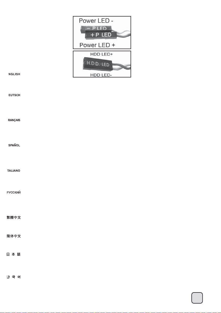
Please refer to the motherboard manuals for
the motherboard’s “Front Panel Connector ” or “System Panel Connector” pin definition.; the white/black wires are negative while other colors are
positive wires. The Power LED wires are separate pins for compatibility with different motherboard pin definition so please make sure they are
connected in the right polarity by referring to your motherboard manual.
Bitte suchen Sie in der Motherboard-Dokumentation nach der Pinbelegung der Anschlüsse des Frontbedienfeldes („Front Panel Connectors“ oder „
System Panel Connectors“). Die weißen/ schwarz Adern sind negativ (-), die farbigen Adern positiv (+).Die Kabel für die Betriebsanzeige-LED sind
zur Kompatibilität mit unterschiedlichsten Motherboards einzeln, nicht als kompletter Stecker ausgeführt. Achten Sie hier bitte auf die richtige Polarität,
lesen Sie in der Dokumentation Ihres Motherboards nach.
Veuillez-vous référer au manuel de votre carte mère pour la description des broches "des connecteurs du panneau frontal" et des broches "des
connecteurs du panneau système". Les câbles colorés en blanc/noir sont négatifs alors que ceux d'une autre couleur sont positifs. Les câbles de la
LED Power sont séparés afin d'être compatible avec différentes cartes mères, donc vérifiez bien qu'ils sont branchés avec la bonne polarité en vous
référant au manuel de votre carte mère
Por favor, consulte en los manuales de la placa base la configuración de pines del “Conector de panel frontal” ó “Conector de panel de sistema” de
su placa base. Los cables de color blanco/negro son negativos mientras que los de color son positivos. Los cables LED de potencia tienen pines
separados para compatibilidad con diferentes definiciones de pines de la placa base luego por favor, asegúrese de que están conectados en la
polaridad correcta consultando el manual de su placa base.
Fare riferimento al manuale della scheda madre nella sezione “Connettori del pannello frontale” o “Connettori del pannello di sistema”. I cavi di colore
bianco/nero sono il polo negativo, mentre quelli di colore diverso il positivo.
Описание контактов разъемов приведены в разделах “Разъемы передней панели” или “Разъемы системной панели” руководства
пользователя материнской платы. Белые/черный провода - отрицательной полярности, цветные провода - положительной полярности.
Провода светодиодного индикатора питания имеют отдельные контакты для совместимости с различными типами контактов материнских
плат, поэтому обратитесь к руководству пользователя материнской платы
請參考主機說明書的Front Panel Connectors安裝Pin Define,將Connector插上; 白/黑色線的部分為負極,彩色線的部分是正極。
Power LED為了適應各主機板的不同, 特別設計為散Pin樣式,請安心使用。
请参考说明书的Front Panel Connectors安装Pin Define,将Connector插上;白/黑色线的部份为负极,彩色线的部份为正极。
Power LED为了适应主机板的不同, 特别设计为散Pin样式,请安心使用。
マザーボードの「フロントパネルコネクタ」または「システムパネルコネクタ」ピン配列についてはマザーボードマニュアルを参照してください。
白/黑色のリード線はマイナスで、色の着いたリード線がプラスです。電源LEDリード線は種々のマザーボードピン定義と互換性を持たせるため分離
されたピンとなっているので、ご使用のマザーボードマニュアルを参照して、適切な極性に接続されるようお確かめください。
메인보드 매뉴얼의 전면패널 커넥터 혹은 시스템패널 커넥터 핀을 참조하기 바랍니다. 하얀/검은선의 경우 음극이며, 다른 색의 경우
양극입니다. 파워 LED 선은 분리되어 다양한 메인보드에서 동작할 수 있도록 되어 있습니다. 그러므로 메인보드 매뉴얼을 참조하여 올바를
극성을 주의해 선택하시기 바랍니다.
и убедитесь, что полярность соблюдена.
18
Page 20

Front I/O connector guide
Below are the front I/O connectors pin definition, please also check your motherboard manual to cross reference with motherboard’s
front I/O pin headers.
Nachstehend finden Sie die Pinbelegung der vorderen E/A-Anschlüsse; bitte gleichen Sie zudem das Handbuch Ihres Motherboards mit
den vorderen E/A-Pinzuweisungen ab.
Au dessous de la description des broches des ports d'E/S, veuillez aussi vérifier sur le manuel de votre carte mère de manière croisée
que les broches sont correctement placées.
A continuación se detallan los pines para conectores E/S frontales, compruebe también por favor el manual de su placa base para
cotejar los pines E/S frontales de la misma.
Di seguito lo schema delle connessioni I/O frontali, confrontare lo schema con quanto riportato sul manuale della scheda madre per
effettuare un controllo incrociato.
Ниже приведено описание контактов передних разъемов ввода/вывода. Обратитесь также к руководству пользователя материнской
платы за описанием передних разъемов ввода/вывода типа "пин-хедер".
下表為Front I/O Connectors的Pin Define,請參閱主機板說明書的各Front I/O Connectors Pin Define一一核對。
下表为Front I/O Connectors的Pin Define,请参阅主机板说明书的各Front I/O Connectors Pin Define一一核对。
以下はフロントI/Oコネクタピン配列ですが、お持ちのマザーボードのフロントI/Oピンヘッダは、マザーボードマニュアルをご参照
ください。
아래는 전면 I/O 커넥터의 핀 사양입니다. 메인보드 매뉴얼을 참조해, 메인보드의 전면 I/O 핀사양을 재 확인한
후 설치합니다.
19
Page 21

Component size limitations
The FT04 can accommodate all standard size components and even some that
are out of spec, please refer to the following guidelines for component selection
and future upgrade considerations:
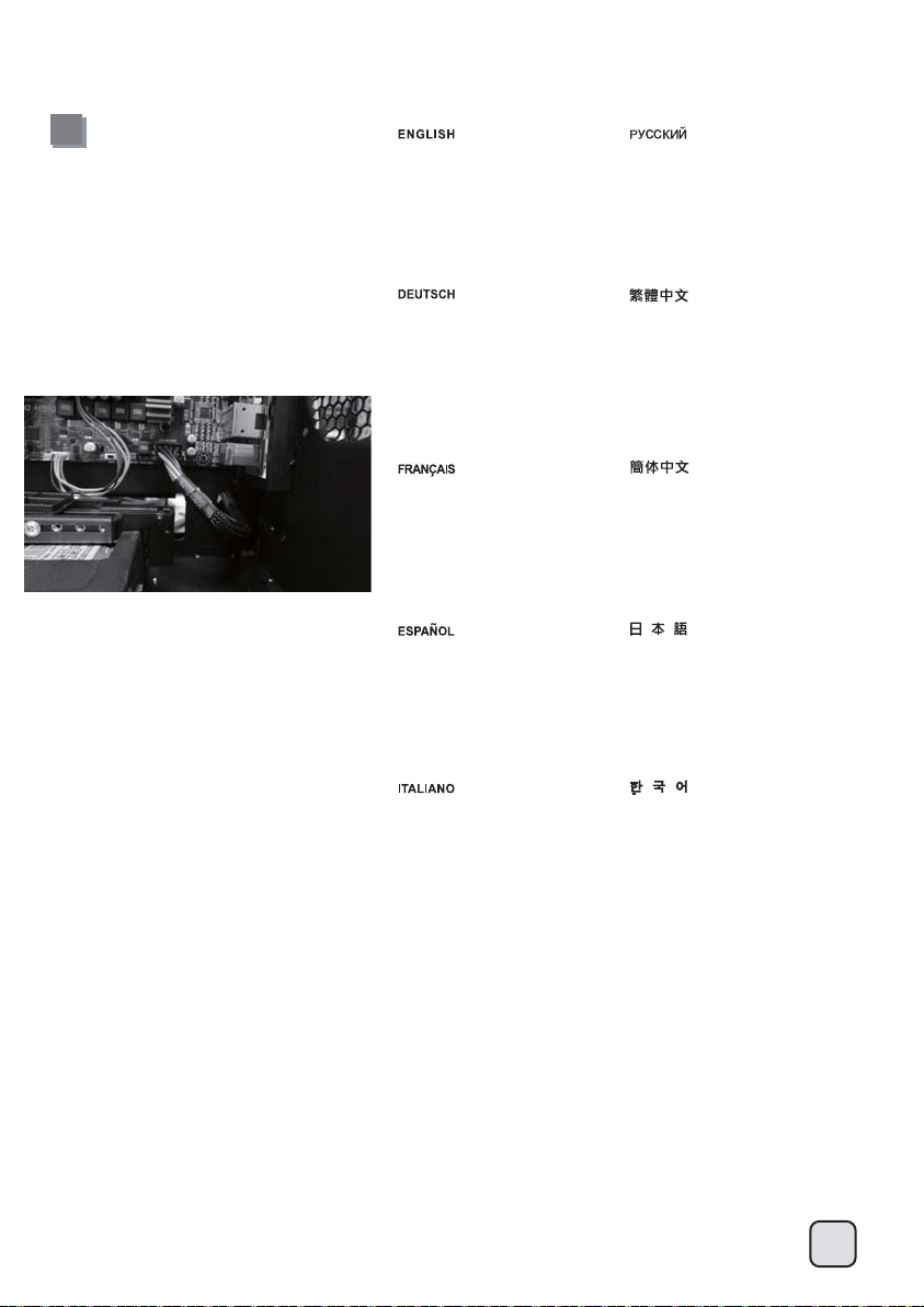
(1) CPU Cooler limitation
The height limit is 165mm and there is 13mm of clearance around the motherboard’s top edge.
The clearance toward the front of the case is variable depending on how much you fill the hard drive cage.
There is 223mm of clearance from the end of an installed hard drive to the motherboard minus a approximately 11mm for a 90 degree angled SATA
connector (less room with 180 degree connectors). If you intend to fill the drive cage, please install CPU fan on the rear side of the CPU cooler as
shown in the photo illustration to avoid interference.
Das Höhenlimit beträgt 165 mm, an der Oberkante des Motherboards verbleiben 13 mm Freiraum.
Der Freiraum zur Front des Gehäuses hin ist variabel und hängt davon ab, wie die Laufwerkhalterung gefüllt wurde. Zwischen dem Ende einer
installierten Festplatte und dem Motherboard verbleiben 223 mm Freiraum abzüglich etwa 11 mm bei um 90 ° abgewinkelten SATA-Verbindern
(bei 180 °-Verbindern bleibt weniger Platz frei). Wenn Sie die Laufwerkhalterung bestücken möchten, installieren Sie den CPU-Lüfter bitte an der
hinteren Seite des CPU-Kühlers (siehe Foto), damit es nicht zu Kollisionen kommt.
La hauteur maximale est de 165mm et il y a une espace de 13mm autour du bord supérieur de la carte mère.
L'espace vers l'avant du boîtier varie selon la façon dont vous avez remplie le casier à disques durs. Il y a un espace de 223mm entre le bord des
disques durs installés et de la carte mère moins approximativement 11mm pour un connecteur SATA à 90 degrés (encore moins d'espace avec un
connecteur standard à 180 degrés). Si vous essayez de remplir le casier à lecteurs, veuillez le ventilateur à l'arrière du dissipateur de processeur
comme montré sur l'illustration afin d'empêcher toutes interférences.
La altura límite es de 165mm y existe un espacio de 13mm alrededor del extremo superior de la placa base. El espacio hacia el frontal de la carcasa
es variable dependiendo de lo mucho que llene la carcasa para discos duros. Existe un espacio de 223mm hacia el final de un disco duro instalado
en la placa base menos unos 11mm para un conector SATA en ángulo de 90 grados (menos espacio con conectores de 180 grados) Si pretende
llenar la carcasa para discos duros, por favor instale el ventilador para CPU en el lateral del disipador de la CPU como se muestra en la foto para
evitar interferencias.
Il limite in altezza è di 165mm e ci sono 13mm di tolleranza intorno al bordo superiore della scheda madre.
La tolleranza verso la parte frontale del case dipende da quanti hard drive sono installati nel supporto. Ci sono 223mm di tolleranza tra l’estremità di
un hard drive installato e la scheda madre meno approssimativamente 11mm di un connettore SATA a 90° (meno spazio con connettori a 180°). Se
intendete riempire il supporto hard drive, installate la ventola della CPU nella parte posteriore del dissipatore come mostrato in figura, per evitare
interferenze.
Максимальная высота кулера – 165 мм, и зазор вокруг верхнего края материнской платы должен составлять 13 мм. Зазор до передней
панели корпуса зависит от количества устройств в кронштейне для жестких дисков. Зазор должен составлять 223 мм от края
установленного жесткого диска до материнской платы минус приблизительно 11 мм для углового SATA-разъема (90 градусов)
(с плоскими разъемами (180 градусов) остается меньше места). Если предполагается полностью заполнить кронштейн для жестких дисков,
установите вентилятор ЦП на заднюю панель процессорного кулера, как показано на рисунке, чтобы он не мешал прокладке кабелей.
Cooler限高是165mm,Cooler外緣允許超出主機板上邊界13mm。
Cooler前邊界則需要視您需不需要安裝大量硬碟,硬碟尾部距離主機板後端有223mm,再扣除90度線材所需要最短的空間11mm。如果您購買的主機
板CPU位置比較前面,建議您可以如下圖把CPU風扇安裝在Cooler後方,避免硬碟線材干擾扇葉。
Cooler限高是165mm,Cooler外缘允许超出主机板上边界13mm。
Cooler前边界则需要视您需不需要安装大量硬盘,硬盘尾部距离主机板后端有223mm,再扣除90度线材所需要最短的空间11mm。如果您购买的主机
板CPU位置比较前面,建议您可以如下图把CPU风扇安装在Cooler后方,避免硬盘线材干扰扇叶。
高さ制限は165mmであり、マザーボード上の周囲に38mmの隙間があります。
ハードドライブケージに何台装着するかによって、ケース正面への距離は変わります。インストールされたハードドライブの終わりからマザーボード
までから約11mm引くと、90度角のSATAコネクタ(180度コネクタより少ない空間)のために223mmの隙間があります。ドライブケージに全装着するつ
もりであれば、干渉を避けるために、CPUファンを写真説明に示すようにCPUクーラーの後ろ側にインストールしてください。
높이는165mm로 제한되며, 메인보드의 상부 가장자리와13mm의 간격이 있습니다. 케이스 전면과의 여유 공간은 얼마나 많은 드라이브를
설치하는가에 따라 다릅니다. 설치된 드라이브로 부터 메인보드까지 약223mm의 여유 공간이 있고,90도 SATA 커넥터를 사용할 경우 11mm가 줄어
듭니다. (일반180도 커넥터를 사용할 경우 이 공간은 더 줄어듭니다. ) 만약 드라이브 케이지를 다 채우게 될 경우 CPU쿨러의 팬을 그림에서와 같이
CPU쿨러의 뒷쪽에 장착하여 서로 간섭되는 것을 방지 합니다.
20
Page 22

Component size limitations
(2) Power supply and optical drive limitation
(A) (B-1) (B-2)
A: Length limitation
The Total length for power supply and optical drive: Power supply and the optical drive space in the FT04 share the same plane so the total limit is 439mm including possible room
for cables. We recommend maximum size for power supply of up to 220mm such as the SilverStone’s ST1500. Maximum length limitation for PSU only is 285mm.
( (A) The absolute maximum length for optical drive is 225mm. Once the optical drive length surpasses 225mm, it will start to encroach the cable routing hole to the right of the power
supply compartment.)
B: Power supply cable length recommendation
( (B-1) Below is the recommended cable length for retail ATX motherboards. If the cables are not long enough, please purchase extension cables.)
( (B-2) When using a non-modular PSU with a depth of 140mm, route the CPU 8/4 Pin through the indicated hole first. PP04 or PP07, extension cables can be used if the cable is
not long enough.)
A: Längenbeschränkung
Gesamtlänge Netzteil und optisches Laufwerk: Netzteil und optisches Laufwerk liegen beim FT04 in derselben Ebene; daher stehen maximal 439 mm einschließlich Raum für Kabel
zur Verfügung. Wir empfehlen Netzteile mit einer maximalen Größe bis 220mm, z. B. das SilverStone ST1500. Das Netzteil darf nur maximal 285 mm lang sein.
( (A) Die absolute Maximallänge von optischen Laufwerken liegt bei 225 mm. Überschreitet die Länge des optischen Laufwerks 225 mm, wird dadurch die Kabelführungsöffnung rechts
neben dem Netzteil beeinträchtigt.)
B: Netzteilkabel – Längenempfehlungen:
( (B-1) Below is the recommended cable length for retail ATX motherboards. If the cables are not long enough, please purchase extension cables.)
( (B-2) Bei Einsatz eines nicht-modularen Netzteils mit einer Tiefe von 140 mm führen Sie zunächst den 8/4-poligen CPU-Anschluss durch das angezeigte Loch. Sie können die
Verlängerungskabel PP04 oder PP07 verwenden, falls das Kabel nicht lang genug ist.)
A: Limitation de longueur
Longueur totale de l'alimentation et du lecteur : Les logements pour l''alimentation et le lecteur optique partage le même plan dans le FT04 est dispose d'un longueur limite de 439mm
en incluant l'espace pour les câbles. Nous vous recommandons une taille maximale pour l'alimentation de 220mm comme la SilverStone ST1500. La limite maximum de longueur de
PSU est seulement de 285 mm.
( (A) La taille maximale des lecteurs optique est de 225mm. Si le lecteur optique dépasse les 225mm, il commencera à occuper l'espace destiné au trou du compartiment de
l'alimentation utilisé pour faire passer les câbles. )
B: Recommandations de longueurs des câble de l'alimentation:
( (B-1) Below is the recommended cable length for retail ATX motherboards. If the cables are not long enough, please purchase extension cables.)
( (B-2) Quand vous utilisez un PSU non-modulaire d'une profondeur de 140 mm, placez d'abord la broche 8/4 du CPU à travers le trou indiqué. PP04 ou PP07, les rallonges peuvent
être utilisées si le câble n'est pas assez long.)
A: Limitación de longitud
Longitud total de la fuente de alimentación y dispositivo óptico: El espacio de la fuente de alimentación y el dispositivo óptico en la FT04 comparten el mismo plano, luego el límite
total es 439mm, incluyendo espacio posible para cables. Le recomendamos un tamaño máximo de la fuente de alimentación de hasta 220mm, como la Silverstone ST1500.
La limitación de longitud máxima para una FA es solo de 285mm.
( (A) La longitud máxima absoluta para un dispositivo óptico es de 225mm. Una vez la longitud del dispositivo óptico sobrepasa los 225mm, empezará a ocupar el espacio del agujero
de enrutado a la derecha del compartimento de la fuente de alimentación)
B: Recomendaciones de la longitud del cable de la fuente de alimentación:
( (B-1) Below is the recommended cable length for retail ATX motherboards. If the cables are not long enough, please purchase extension cables.)
( (B-2) Cuando se usa una FA no modular con una profundidad de 140mm, enrute primero los 8/4 pines de la CPU a través del agujero indicado. Bien PP04 ó PP07, los cables de
extensión se pueden usar si el cable no es lo bastante largo.)
A: Limite in lunghezza
Lunghezza totale per alimentatore e drive ottico:
Lo spazio per l’alimentatore ed il drive ottico, nel case FT04, condividono lo stesso piano che ha una lunghezza totale di 439mm incluso lo spazio per eventuali cavi. Vi raccomandiamo
di scegliere alimentatori con lunghezza massima di 220mm come il SilverStone ST1500. La limitazione della lunghezza massima solo per la PSU è di 285 mm.
( (A) La lunghezza massima assoluta per il drive ottico è di 225mm. Una volta che il drive ottico supera i 225mm, inizierà ad interferire con il foro per il cable routing disposto alla destra
della zona dell’alimentatore.)
B: Raccomandazioni per la lunghezza dei cavi dell’alimentatore:
( (B-1) Below is the recommended cable length for retail ATX motherboards. If the cables are not long enough, please purchase extension cables.)
( (B-2) Quando si usa una PSU non modulare con una profondità di 140 mm, prima infilare nel foro indicato i pin 8/4 della CPU. Se il cavo non è sufficientemente lungo, possono
essere usati cavi di prolunga PP04 o PP07.)
21
Page 23

A. Ограничение на длину
Общая длина блока питания и приводов оптических дисков:
Блок питания и привод оптических дисков в корпусе FT04 расположены на одной панели, поэтому их общая длина не может превышать 439 мм, включая возможное
пространство для кабелей. Рекомендуется использовать блок питания длиной не
питания составляет 285 мм.
( (A) Максимально допустимая длина привода оптических дисков составляет 225 мм. Если длина привода оптических дисков превышает 225 мм, он будет блокировать
отверстие для прокладки кабелей в правой части отсека блока питания.)
B: Power supply cable length recommendation
( (B-1) Below is the recommended cable length for retail ATX motherboards. If the cables are not long enough, please purchase extension cables.)
( (B-2) При использовании немодульного блока питания с глубиной 140 мм сначала пропустите разъем процессора 8/4 через показанное отверстие. В случае, если длина
кабеля окажется недостаточной, в корпусах PP04 или PP07 можно использовать удлинительные кабели.)
A:長度限制
PSU與光碟機的總合限制: FT04的電源供應器與光碟機相對,允許的總長度是439mm,需另外再扣除線材所需空間。我們建議最大安裝到220mm長的電源供應器,
例如銀欣ST1500電源。在不安裝光碟機單獨安裝電源供應器的情況下,電源長度限制是285mm。
( (A) 光碟機長度限制為225mm,若光碟機超過225mm,將會擋住電源左邊的背位理線孔。)
B: 電源線材建議長度:
以下是以一般市售ATX主機板抓出來的各線材建議長度列表,請先確認電源線長度是否足夠如果不夠請選購所需要的延長線
( (B-1) Below is the recommended cable length for retail ATX motherboards. If the cables are not long enough, please purchase extension cables.)
( (B-2) 如果您使用非模組化的電源供應器,電源深度為140mm。 CPU 8/4 Pin線材請優先由這個小洞穿過,這是最短的走線距離。如果您的線材長度還是不足,建議您可以選購
銀欣PP04或PP07延長線加以延長。)
A:长度限制
PSU与光驱的总合限制:
FT04的电源供应器与光驱相对,允许的总长度是439mm,需另外再扣除线材所需空间。我们建议最大安装到220mm长的电源供应器,例如银欣ST1500电源。在不安装光驱单独安装电源
供应器的情况下,电源长度限制是285mm。
( (A) 光驱长度限制为225mm,若光驱超过225mm,将会挡住电源左边的背位理线孔。)
B:电源线材建议长度:
以下是以一般市售ATX主机板抓出来的各线材建议长度列表,请先确认电源线长度是否足够如果不够请选购所需要的延长线
( (B-1) Below is the recommended cable length for retail ATX motherboards. If the cables are not long enough, please purchase extension cables.)
( (B-2) 如果您使用非模块化的电源供应器,电源深度为140mm。 CPU 8/4 Pin线材请优先由这个小洞穿过,这是最短的走线距离。如果您的线材长度还是不足,建议您可以选购
银欣PP04或PP07延长线加以延长。)
A: 長さ制限
電源および光学ドライブの全長:
電源と光学ドライブはFT04内で同じ面を共有した配置なので、ケーブルのための余裕を含んだ合計長さ限度は439mmです。電源に対しては、SilverStoneのST1500.などの最大サ
イズ220mmの電源が推薦されます。PSUのための最大の長さ制限は、285mmであるだけです。
( (A) 光学ドライブのための最大絶対長は225mmです。光学ドライブ長が225mmを超えると、それは電源コンパートメント右へのケーブル通しホールにカブり始めます。)
B:電源ケーブル推奨長さ:
( (B-1) Below is the recommended cable length for retail ATX motherboards. If the cables are not long enough, please purchase extension cables.)
( (B-2) 140mmの深さで非モジュラーPSUを使うとき、8/4が最初に示された穴を通してピンでとめるCPUを送ってください。PP04またはPP07、ケーブルが十分に長くないならば、
拡張ケーブルが使われることができます。)
A: 길이 제한
파워 서플라이와 광드라이브의 총 길이 제한.
파워서플라이와 광드라이브 는 FT04에 있어서 동일한 공간을 사용하며, 케이블에 필요한 여유공간을 감안하여 총 사용가능 길이는 439mm입니다. 파워 서플라이의 경우
SilverStone의 ST1500와 같이 220mm 까지의 파워 서플라이 사용을 권장합니다. PSU만의 최대 길이 제한은 285mm입니다.
( (A) 광드라이브를 위한 최대 공간은 225mm 입니다. 광드라이브가 225mm를 상회할 경우 파워 서플라이 오른쪽의 케이블 정리 공간과 간섭이 일어나기 시작합니다.)
B: 파워 서플라이 케이블 길이 및 권장사항
( (B-1) Below is the recommended cable length for retail ATX motherboards. If the cables are not long enough, please purchase extension cables.)
( (B-2) 깊이가 140mm인 비모듈식 PSU를 사용하는 경우, 먼저 CPU 8/4 핀을 표시된 구멍을 통과시키십시오. 케이블의 길이가 충분히 길지 않을 경우 확장 케이블 PP04 또는
PP07을 사용할 수 있습니다.)
более 220 мм, например модель SilverStone ST1500. Ограничение по длине для блока
Component size limitations
(3) Graphics card/expansion card length limitation
FT04 can support 13.3”(338mm) consumer level graphics cards.
Das FT04 nimmt bis zu 338 mm lange Grafikkarten auf.
Le FT04 est compatible avec les cartes graphiques de 13.3” ou 338 mm.
La FT04 puede aceptar tarjetas gráficas de hasta 13,3” (338mm).
FT04 può supportare schede grafiche con una lunghezza massima di 13,3” (338mm).
FT04 поддерживает графические карты потребительского уровня размером 13,3 дюйма (338 мм)
FT04支援到PCIE規格定義的上限長度為13.3”帶把手的顯示卡。
如果您還是有安裝不下的顯示卡,請與我們聯繫,並告知我們顯示卡的廠牌與型號,由我們協助您後續安裝事宜。
FT04支持到PCIE规格定义的上限长度为13.3”带把手的显示卡。
如果您还是有安装不下的显示卡,请与我们联系,并告知我们显示卡的厂牌与型号,由我们协助您后续安装事宜。
FT04は13.3インチ(338mm)の市販グラフィックカードをサポートできます。
FT04은 최대 13.3”(338mm)의 그래픽 카드를 지원합니다.
22
Page 24
Component size limitations
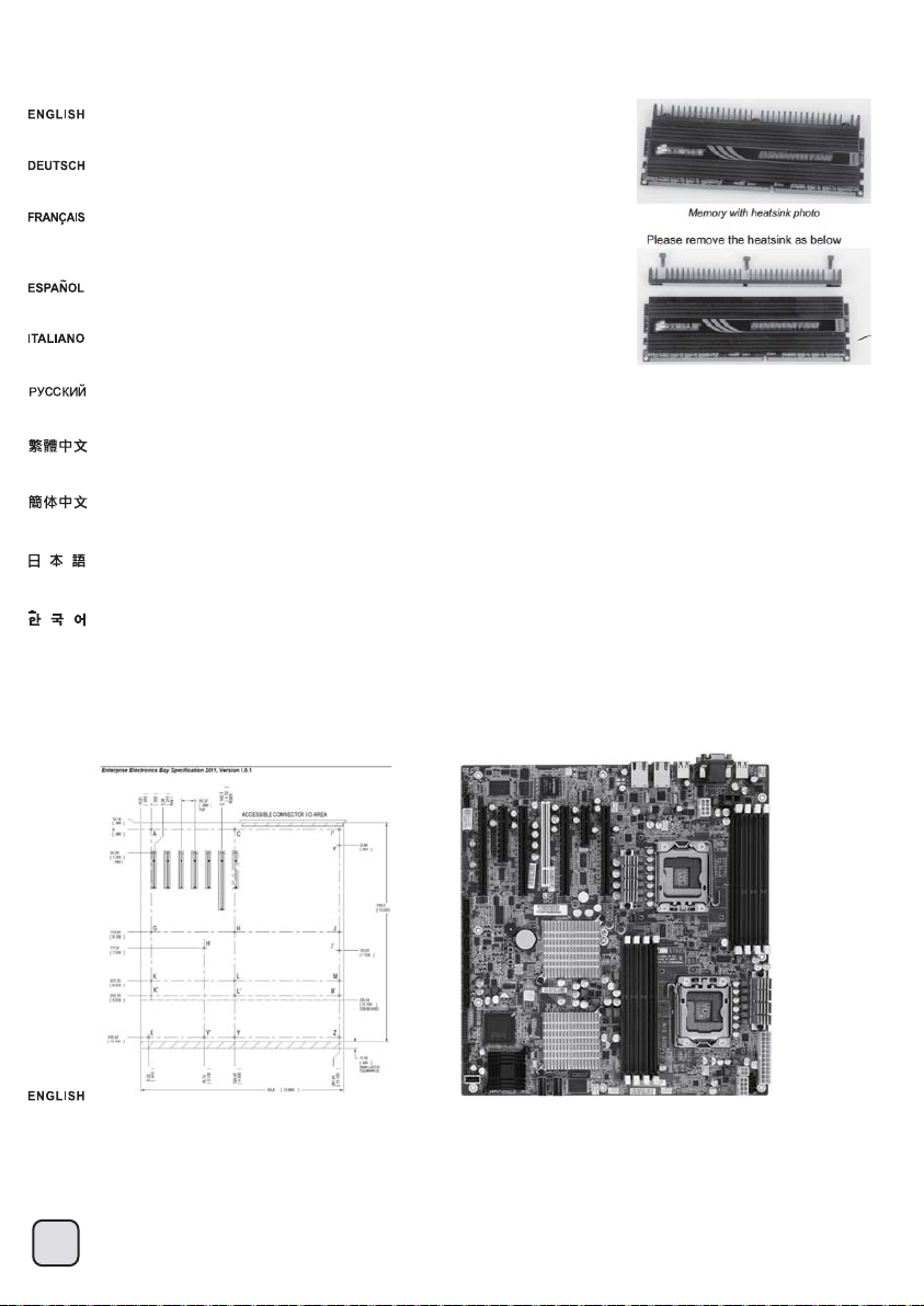
(4) Memory height limitation
There is 61mm of distance between the motherboard to the hard drive. If you use a memory
similar to the one shown in the illustration, please remove the heatsink on it prior to installation.
Zwischen Motherboard und Festplatte verbleiben 61 mm Platz. Sofern Sie Speichermodule
verwenden, die dem Modul in der Illustration ähneln, entfernen Sie vor der Installation den Kühlkörper.
Il y a une distance de 61mm entre la carte mère et les disques durs. Si vous avez des barrettes
mémoires similaires à celles montrées dans l'illustration, veuillez démonter les dissipateurs avant de
les installer.
Existe una distancia de 61mm desde la placa base hasta el disco duro. Si usa una memoria similar a la
que se muestra en la ilustración, quite por favor el radiador antes de la instalación
Ci sono 61mm di distanza tra la scheda madre e l’hard drive. Se utilizzate memorie simili a quelle
mostrate in foto, rimuovete il dissipatore superiore prima dell’installazione.
Расстояние между материнской платой и жестким диском должно составлять 61 мм. При использовании модуля памяти,
аналогичного показанному на рисунке перед установкой снимите с него радиатор.
從主機板表面至硬碟的距離有61mm ,視您的主機板而定。主硬碟架上的硬碟有可能會檔在記憶體上方,如果你有如類似下圖的記憶體,
請移除上面的Heatsink部分。
从主机板表面至硬盘的距离有61mm ,视您的主机板而定。主硬盘架上的硬盘有可能会文件在内存上方,如果你有如类似下图的内存,
请移除上面的Heatsink部分。
マザーボードからハードドライブまでは61mmの距離があります。図示されたものに類似したメモリを使う場合、装着に先がけてそれの上のヒートシンクを
取り外してください。
메인보드에서 하드 드라이브까지 61mm의 공간 여유가 있습니다. 아래 그림과 유사한 메모리를 사용할 경우 설치 전에 히트싱크를
제거하시기 바랍니다.
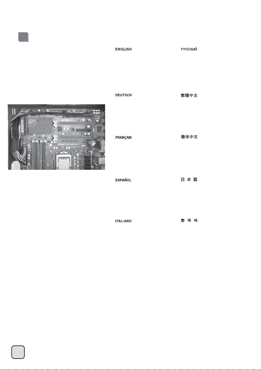
Component size limitations
(5) Motherboard size limitation
FT04 supports up to SSI-EEB (Extended ATX motherboard), New generation of SSI-CEB server or workstation motherboards no longer require
CPU cooler mounting holes on the motherboard tray. Coolers can now be installed directly on the motherboard. As a result, we eliminated support
for SSI-CEB CPU cooler mounting holes and instead increased the large gap on the motherboard tray to support CPU cooler back plates swapping
with more LGA 1156/1155 motherboards. The FT04 chassis’ support for new and future SSI-CEB motherboards should be unaffected by this
change.
Note: FT04 has standard screw hole for motherboards and does not include additional screw hole that some server motherboards require.
23
Page 25

FT04 unterstützt maximal SSI-EEB (Extended-ATX-Motherboard) Hochmoderne Motherboards von SSI-CEB-Servern und -Arbeitsrechnern
benötigen keine Löcher zur CPU-Kühlermontage am Motherboard-Einschub mehr. Die Kühler können nun direkt am Motherboard installiert werden.
Dadurch haben wir die Unterstützung der Löcher zur SSI-CEB-CPU-Kühlermontage aufgegeben und stattdessen den Abstand am
Motherboard-Einschub vergrößert; dadurch werden CPUKühlerrückplatten unterstützt, die mit einer größeren Anzahl an
LGA 1156-/1155-Motherboards kompatibel sind. Die Unterstützung neuer und zukünftiger SSI-CEB-Motherboards durch das FT04-Gehäuse wird
durch diese Änderung nicht beeinflusst.
Hinweis: Das FT04 hat ein Standardschraubenloch für Motherboards; es verfügt über kein zusätzliches Schraubenloch, das einige
Server-Motherboards benötigen.
FT04 supporte jusqu'à SSI EEB-(carte mète Extended ATX) Les portes-carte mère destinés à la nouvelle génération de cartes mères pour station
de travail ou serveur SSI-CEB n'ont plus besoin de trous de montage pour le refroidisseur de l'unité centrale. Les refroidisseurs peuvent désormais
s'installer directement sur la carte mère. Nous avons ainsi éliminé le support destiné aux trous de montage pour le refroidisseur de l'unité centrale
SSI-CEB. L'espace sur le porte-carte mère permettant de permuter les plaques arrière du refroidisseur, avec plus de cartes mères LGA 1156/1155,
est agrandi. Le support du châssis FT04 pour les nouvelles cartes mères SSI-CEB et celles à venir, ne sera pas affecté par cette modification.
Note : FT04 a un trou de vis standard pour les cartes mères et n'inclut pas de trou de vis supplémentaire que certains serveurs de
carte-mère demandent.
La FT04 acepta hasta SSI-EEB (Placa base ATX Extendida) la nueva generación de servidores SSI-CEB ó placas base para estaciones de trabajo
ya no precisan de agujeros de montaje en la bandeja de la placa base para el disipador de la CPU. Ahora puede instalar los disipadores
directamente sobre la placa base. Como resultado, eliminamos los agujeros de montaje para disipadores SSI-CEB de la CPU y en cambio
aumentamos el gran hueco en la bandeja de la placa base para así poder aceptar el cambio de placas traseras para CPU con más placas base
LGA 1156/1155. La compatibilidad del chasis de la FT04 con placas base SSI-CEB nuevas y futuras no debería verse afectada con este cambio.
Nota: La FT04 tiene un agujero de tornillo estándar para placas bases y no incluye un agujero para tornillo adicional que algunas placas base
para servidor precisan.
FT04 supporta schede madre SSI-EEB (ATX estesa) La nuova generazione di schede madri per server o workstation in formato SSI-CEB non
richiede più i fori di montaggio dei dissipatori sui supporti delle mainboard stesse. I cooler possono essere ora montati direttamente sulla scheda
madre. In conseguenza di ciò sono stati eliminati i fori specifici ed è stata ricavata un’apertura di maggiori dimensioni nel supporto della
motherboard. Questo ha permesso di aumentare l’accessibilità al back plate della CPU in un maggior numero di schede basate su socket
LGA 1156/1155. Il supporto alle nuove e future motherboard SSI-CEB non è e non sarà influenzato da questo cambiamento.
Nota: FT04 ha un foro standard per le schede madri e non include altri fori richiesti per alcune schede madre server.
FT04 обеспечивает поддержку до SSI-EEB (расширенная системная плата ATX) Материнским платам SSI-CEB нового поколения для
серверов и рабочих станций больше не требуются монтажные отверстия для процессорного кулера на кронштейне материнской платы.
Теперь кулеры можно устанавливать непосредственно на материнскую плату. Поэтому в корпусе теперь отсутствуют монтажные
отверстия под процессорный кулер для материнских плат
крепежных пластин процессорного кулера, которыми теперь оснащается все больше материнских плат с разъемом LGA 1156/1155. Это
изменение не должно повлиять на совместимость корпуса FT04 с новыми и будущими моделями материнских плат SSI-CEB.
Примечание. В корпусе FT04 имеется стандартное отверстие под винт для системной платы, но отсутствует дополнительное отверстие
под винт, которое требуется для некоторых серверных системных плат.
SSI-CEB и увеличен зазор на кронштейне материнской платы для поддержки
FT04最大支援至SSI-EEB(俗稱E-ATX)規格主機板 圖: 新一代SSI-CEB規格伺服器主機板,已經沒有依照SSI規範的Xeon Cooler在機殼上的鎖固孔位,
其Cooler本身是鎖在主機板上。我們新一代的機殼為了配合LGA1156/1155的位置,將主機板底板對應的開孔加大,因而取消了SSI規範上的Cooler
鎖固螺柱。並不是不相容於SSI CEB主機板,只是因應主機板規格的演進而修改設計。
須請您注意的事是,許多伺服器主機板可能會有多增加一些非標準的鎖固孔位。
FT04只會有規範上應該有的鎖固孔位。
FT04最大支持至SSI-EEB(俗称E-ATX)规格主机板 新一代SSI-CEB规格服务器主机板,已经没有依照SSI规范的Xeon Cooler在机壳上的锁固孔位,
其Cooler本身是锁在主机板上。我们新一代的机壳为了配合LGA1156/1155的位置,将主机板底板对应的开孔加大,因而取消了SSI规范上的Cooler
锁固螺柱。并不是不兼容于SSI CEB主机板,只是因应主机板规格的演进而修改设计。
须请您注意的事是,许多服务器主机板可能会有多增加一些非标准的锁固孔位。
FT04只会有规范上应该有的锁固孔位。
FT04はSSI-EEB(拡張ATXマザーボード)までサポートしています。 新世代のSSI-CEBサーバまたはワークステーションマザーボードは、マザーボードトレイ
上のCPUクーラー設置孔をもはや必要としていません。クーラーは現在直接マザーボードに装着できます。結果として、弊社はSSI-CEB CPUクーラー設置
孔サポートをやめ、代わりに、より多くのLGA1156/1155マザーボードと互換性のあるCPUクーラー後部プレートをサポートするため、マザーボードトレイ上の
ギャップをより増大させました。 この変更は、FT04ケースの新しい、将来のSSI-CEBマザーボードへのサポートには影響しません。
注:FT04はマザーボードのために標準的なネジ穴を持って、何枚かのサーバー・マザーボードが必要とする更なるネジ・ホールを含みません。
FT04은 SSI-EEB(Extended ATX 메인보드)까지 지원합니다. SSI-CEB 서버나 워크스테이션은 더이상 메인보드 트레에에 CPU 쿨러 마운팅 홀을
필요로 하지 않습니다. 쿨러가 메인보드에 직접 장착이 가능하고, 그 결과 SSI-CEB 쿨러 마운팅 홀을 제거 했으며, 메인보드 트레이에 큰 공간을
두어 LGA1156/1155 을 지원하는 보다 많은 메인보드 CPU 쿨러 백플레이트를 지원 할 수 있게 하였습니다. 이런 변화들은 SSI-CEB 메인보드
신제품 혹은 미래에 출시될 제품을 지원하는데 영향이 없을 것입니다.
참고: FT04에는 메인보드를 고정하기 위한 표준 나사 구멍이 있으나, 일부 서버 메인보드에 필요한 추가 나사 구멍은 없습니다.
24
Page 26
CPU and graphic card supporter
A-1 A-2 A-5 A-6A-3 A-4
A : CPU Cooler Supporter
(1) First set the chassis on its side, make sure it is on a level surface.
(2) The CPU supporter has already been installed in a commonly used position. You can loosen the screw in the middle to fully extend it.
(3) If the supporter position is not optimal for your setup, remove two more screws on left and right side to move the supporter. After finding the optimal position
for your setup, secure with screws.
(4) Move the supporter arm up to touch the installed CPU cooler and then secure the middle screw.
(5) Place the chassis upright to let the CPU cooler rest naturally on the supporter.
(6) Recommended usage range for supporter:
From 13mm beyond edge of the motherboard to 45mm inward from the motherboard edge.
Most 120mm fan based tower-style CPU cooler should be compatible.
B: Graphic card supporter
(1) First set the chassis on its side, make sure it is on a level surface.
(2) Install VGA supporter onto the chassis and adjust it to avoid power connectors on the graphic card.
(3) Install clips onto the VGA supporter according to the installed slot.
Note: if more than one graphic card is installed, avoid installing them adjacent to each other as the clip may not fit between two adjacent graphic cards.
A : CPU Cooler Supporter
(1) Legen Sie das Gehäuse zunächst auf die Seite, achten Sie auf einen ebenen Untergrund.
(2) Falls sich die Halterposition nicht für Ihren Bedarf eignen sollte, entfernen Sie zum Verschieben des Halters zwei weitere Schrauben auf der linken und rechten Seite.
Nachdem Sie die optimale Position gefunden haben, wieder mit den Schrauben fixieren.
(3) Falls sich die Halterposition nicht für Ihren Bedarf eignen sollte, entfernen Sie zum Verschieben des Halters zwei weitere Schrauben auf der linken und rechten Seite.
Nachdem Sie die optimale Position gefunden haben, wieder mit den Schrauben fixieren.
(4) Bewegen Sie den Halterarm nach oben, bis er den installierten CPU-Kühler berührt; anschließend mit der mittleren Schraube fixieren.
(5) Stellen Sie das Gehäuse wieder aufrecht, damit der CPU-Kühler auf dem Halter zu liegen kommt.
(6) Empfohlener Halter-Einsatzbereich:
Von 13 mm jenseits der Motherboard-Kante bis 45 mm von der Motherboard-Kante einwärts.
Die meisten CPU-Tower-Kühler mit 120 mm-Lüfter sollten passen.
B: Graphic card Supporter
(1) Legen Sie das Gehäuse zunächst auf die Seite, achten Sie auf einen ebenen Untergrund.
(2) Installieren Sie den VGA-Träger am Gehäuse; richten Sie ihn so aus, dass er die Netzanschlüsse an der Grafikkarte nicht blockiert.
(3) Installieren Sie entsprechend dem verwendeten Steckplatz Klemmen am VGA-Träger.
Hinweis: Bei Installation mehrerer Grafikkarten dürfen Sie diese nicht nebeneinander installieren, da die Klemme nicht zwischen zwei benachbarte Grafikkarte passt.
A : CPU Cooler Supporter
(1) Premièrement mettez le boîtier sur le côté, vérifiez bien qu'il soit bien à plat
(2) Le support intégré du processeur a déjà été installé dans une position couramment utilisé. Vous pouvez desserrer la vis du milieu pour l'étendre complètement
(3) Si la position du support n'est pas optimale pour votre configuration, retirez deux vis supplémentaires sur les côtés gauche et droit pour bougez le support.
Après avoir trouvé la position optimale pour votre configuration, fixez les vis.
(4) Poussez le bras du support pour toucher le dissipateur de processeur installé et ensuite fixez la vais du milieu.
(5) Remettez le boîtier debout pour laisser le dissipateur du processeur s'appuyer naturellement sur le support.
(6) Intervalle recommandé pour le support:
De au delà de 13mm du bord de la carte mère à 45mm à l'intérieur du bord de la carte mère.
La plupart des dissipateurs de type tour équipé d'un ventilateur de 120mm doivent être compatible.
B: Graphic card supporter
(1) Premièrement mettez le boîtier sur le côté, vérifiez bien qu'il soit bien à plat
(2) Installez le preneur en charge VGA sur le boîtier et réglez-le de façon à éviter les connecteurs électriques de la carte graphique.
(3) Installez les clips du preneur en charge VGA en fonction de la fente installée.
Note : Si plus d'une carte graphique est installée, évitez de les installer en position adjacente l'une de l'autre car le clip peut ne pas s'insérer entre deux cartes graphiques adjacentes.
A : CPU Cooler Supporter
(1) Primero tumbe la carcasa de lado, asegúrese de que está en una superficie lisa.
(2) El soporte de la CPU ya ha sido instalado en una posición de uso corriente. Puede aflojar el tornillo medio para extenderlo por completo.
(3) Si la posición del soporte no es óptima para su configuración, quite dos tornillos más de la izquierda y la derecha para mover el soporte. Tras encontrar la posición
óptima para su configuración, fíjela con tornillos.
(4) Mueve el brazo soporte hasta tocar el disipador de CPU instalado y fije el tornillo medio
(5) Ponga el chasis derecho para dejar que el disipador de la CPU descanse de forma natural en el soporte
(6) Rango de uso recomendado para el soporte:
Desde 13mm más allá del borde de la placa base hasta 45mm hacia el interior del borde de la placa base. La mayoría de los ventiladores de 120mm para disipador de CPU estilo
torre deberían ser compatibles.
B: Graphic card supporter
(1) Primero tumbe la carcasa de lado, asegúrese de que está en una superficie lisa.
(2) Instale el soporte VGA en el chasis y ajústelo para evitar conectores de potencia en la tarjeta gráfica.
(3) Instale los clips en el soporte VGA según el zócalo que se use.
Nota: si se instala más de una tarjeta gráfica, evite ponerlas una junto a la otra, ya que el enganche podría no encajar entre dos tarjetas gráficas adyacentes.
25
Page 27

A : CPU Cooler Supporter
(1) Per prima cosa disporre il cabinet su un fianco, possibilmente su una superficie piana.
(2) Il supporto per il dissipatore è già installato nel case in una posizione standard. Potete allentare le viti al centro per estenderlo completamente.
(3) Se il supporto non si trova in posizione ottimale per il vostro setup, rimuovere due ulteriori viti a destra ed a sinistra per posizionare il supporto stesso. Dopo aver
trovato la corretta posizione per il vostro setup, avvitare nuovamente le viti.
(4) Spostare il braccio del supporto verso l’alto fino a toccare il dissipatore per CPU installato, quindi avvitare le viti al centro.
(5) Rimettere in piedi il cabinet, il dissipatore CPU si appoggerà in modo naturale sul supporto.
(6) Range di utilizzo del supporto:
Da 13mm oltre il bordo della scheda madre a 45mm verso l’interno del bordo stesso.
La maggior parte dei dissipatori a torre con ventola da 120mm dovrebbero essere perfettamente compatibili.
B: Graphic card supporter
(1) Per prima cosa disporre il cabinet su un fianco, possibilmente su una superficie piana.
(2) Installare il supporto VGA sul telaio e regolarlo per evitare i connettori d’alimentazione sulla scheda video.
(3) Installare i fermagli sul supporto VGA in base all’alloggio installato.
Nota: Se è installata più di una scheda video, evitare di installarle una a fianco dell’altra, diversamente i fermagli potrebbero non essere installati tra due schede video adiacenti.
A : CPU Cooler Supporter
(1) Сначала положите корпус набок на ровную поверхность.
(2) Опора процессорного кулера уже установлена в обычном положении. Можно ослабить винты в центре, чтобы полностью выдвинуть ее.
(3) Если положение опоры не соответствует необходимой конфигурации, для перемещения опоры отвинтите еще два винта слева и справа. Подобрав
оптимальное положение, для необходимой конфигурации затяните винты.
(4) Переместите рычаг опоры вверх до соприкосновения с установленным процессорным кулером, а затем закрепите средний винт.
(5) Установите корпус в вертикальное положение, чтобы процессорный кулер лежал на опоре.
(6) Ниже приведены рекомендуемые положения опоры.
От 13 мм наружу от края материнской платы до 45 мм внутрь от края материнской платы. Большинство процессорных кулеров со 120-мм вентиляторами башенного типа
совместимы с данной опорой.
B: Graphic card supporter
(1) Сначала положите корпус набок на ровную поверхность.
(2) Установите планку порта VGA в корпус таким образом, чтобы не допустить соприкосновения с разъемами питания на графической карте.
(3) Установите фиксаторы на планку порта VGA в соответствии с установленным слотом.
Примечание. Если устанавливается более одной графической карты, не устанавливайте их рядом, так как фиксатор может не поместиться между двумя соседними
графическими картами.
A : CPU Cooler Supporter
(1) 請先翻倒機殼,維持機殼平躺。
(2) CPU Cooler支撐架已經預先安裝在適當的位置,請先鬆開前面的螺絲,把支撐架展開。
(3) 如果支撐架的位置不適當,請再移除中間螺絲;將支撐架前後移動至適當位置再鎖固。
(4) 將支撐架展開至剛好接觸到CPU Cooler本體部分的下邊緣,然後鎖固中間的螺絲。
(5) 直立起機殼,Cooler會自然的躺在支架上。
(6) 支撐架的適用範圍:板外13mm~板內45mm 請斟酌使用。我們建議您使用在120mm以上風扇規格的塔型Cooler
B:VGA Supporter
(1) 請先翻倒機殼,維持機殼平躺。
(2) 將顯示卡支撐架鎖上機殼,可前後調整至不擋住顯卡電源插頭的位置。
(3) 視顯示卡槽位而定,鎖上支撐架的掛鉤。注意,如果有多卡安裝時,不要讓顯示卡相鄰安裝,掛勾無法伸入兩張卡之間的縫隙。
A : CPU Cooler Supporter
(1) 请先翻倒机壳,维持机壳平躺。
(2) CPU Cooler支撑架已经预先安装在适当的位置,请先松开前面的螺丝,把支撑架展开。
(3) 如果支撑架的位置不适当,请再移除中间螺丝;将支撑架前后移动至适当位置再锁固。
(4) 将支撑架展开至刚好接触到CPU Cooler本体部分的下边缘,然后锁固中间的螺丝。
(5) 直立起机壳,Cooler会自然的躺在支架上。
(6) 支撑架的适用范围:板外13mm至板内45mm 请斟酌使用。我们建议您使用在120mm以上风扇规格的塔型Cooler
B:VGA Supporter
(1) 请先翻倒机壳,维持机壳平躺。
(2) 将显示卡支撑架锁上机壳,可前后调整至不挡住显卡电源插头的位置。
(3) 视显示卡槽位而定,锁上支撑架的挂钩。注意,如果有多卡安装时,不要让显示卡相邻安装,挂勾无法伸入两张卡之间的缝隙。
A : CPU Cooler Supporter
(1) まず、側面を下にしてケースを置き、水平面にあるのを確かめます
(2) CPUサポーターは一般的に使われる位置にインストール済みです。完全にそれを拡張するには、中間のネジを緩めます。
(3) サポーター位置がセットアップのために最適でないならばサポーターを移動するため左右のネジ2本を外します。セットアップのために最適の位置を見
つけたら、ネジで固定します。
(4) サポーターアームが、インストールされたCPUクーラーに触れるよう移動させ、それから中間のネジを固定します。
(5) CPUクーラーが自然にサポーターに載るよう、ケースを立てて置きます。
(6) サポーターのための推奨使用範囲:
マザーボード縁を13mm越えた位置からマザーボード縁から内側45mmまで。
大部分のタワースタイルCPUクーラー付属の120mmファンは互換性があります。
B: Graphic card supporter
(1) まず、側面を下にしてケースを置き、水平面にあるのを確かめます
(2) VGAサポーターをシャシー上にインストールして、それがグラフィック・カードの上で電力コネクターを避けるように調整してください。
(3) 装置されたスロットによってクリップをVGAサポーター上にインストールしてください。
注:複数のグラフィック・カードが設置されるならば、クリップが2枚の隣接したグラフィック・カードの間で合わないかもしれないので、互いに隣接して彼らを就任させるこ
とを避けてください。
A : CPU Cooler Supporter
(1) 케이스를 옆으로 놓은 후에 평평하게 놓여 있는지 확인합니다.
(2) CPU 서포터는 가장 많이 쓰이는 위치에 이미 장착되어 있습니다. 가운데 있는 나사를 풀어 늘릴 수 있습니다.
(3) 서포터의 위치가 적절하지 않다면, 왼쪽과 오른쪽에 있는 두개의 나사를 더 풀어 서포터를 움직입니다. 적절한 위치를 찾은 후, 나사로
고정시킵니다.
(4) 서포터 암을 움직여 설치된 CPU 쿨러에 닿도록 하고 중간 나사를 조여 고정시킵니다.
(5) 케이스를 바로 세운 후, CPU 쿨러가 서포터에 자연스럽게 닿도록 합니다.
(6) 서포터 사용 권장 범위
메인보드 끝 13mm에서 안쪽을 45mm 까지, 대부분의 120mm 팬 방식의 타워형태 CPU쿨러와 호환됨.
B: Graphic card supporter
(1) 케이스를 옆으로 놓은 후에 평평하게 놓여 있는지 확인합니다.
(2) 섀시에 VGA 지지대를 설치하고 그래픽 카드에 있는 전원 커넥터를 방해하지 않도록 조정하십시오.
(3) 설치된 슬롯에 따라 VGA 지지대에 클립을 설치하십시오.
참고: 2개 이상의 그래픽 카드가 설치된 경우, 클립이 인접한 2개의 그래픽 사이에 들어가지 못할 수 있기 때문에 2개의 그래픽 카드를
서로 인접하게 설치하지 마십시오.
26
Page 28

Optimal Thermal Performance Layout
(1)
If you are installing a tower-style CPU cooler, we recommend that the CPU fan blows rearward to work with FT04’s overall airflow.
Falls Sie einen tower-artigen CPU-Kühler installieren, empfehlen wir, den CPU-Lüfter die Luft nach hinten blasen zu lassen, damit er mit
der gesamten Luftbewegung im FT04 zusammenarbeitet.
Si vous installez un dissipateur de processeur de type "tour", nous vous recommandons que le ventilateur du dissipateur souffle
vers l'arrière pour fonctionner dans le même sens que le flux d'air généré par le FT04 lui-même.
Si está instalando un disipador de CPU para torre, le recomendamos que el ventilador de la CPU ventile hacia trasera para estar
en concordancia con el flujo de aire global de la FT04.
Se scegliete un dissipatore a torre, assicuratevi che il flusso d’aria della ventola sia disposto posteriore, per seguire in modo naturale il flusso interno di FT04.
Если вы устанавливаете башенный кулер ЦП, то мы рекомендуем установить его таким образом, чтобы воздушный поток вентилятора ЦП был направлен задний и
совпадал с общим направлением воздушного потока внутри корпуса FT04.
如果您使用塔型散熱器,我們建議您將散熱器安裝方向為風扇往後吹的方式,以順著FT04的風流
如果您使用塔型散热器,我们建议您将散热器安装方向为风扇往后吹的方式,以顺着FT04的风流
タワースタイルCPUクーラーを取り付ける場合、FT04の全体の気流に合わせた動作のため、CPU のエアーが後方に送られるようにお勧めします。
만약 타워 스타일의 CPU 쿨러를 사용한다면, CPU 팬이 후방으로 향하도록 하여, FT04의 전체적인 공기흐름과 잘 조화되도록 합니다.
Optimal Thermal Performance Layout
(2)
When choosing a graphics card, we recommend models that have fan blowing exhaust air to the rear slot, this will ensure smooth and efficient airflow within the FT04 for
maximum cooling performance.
Bei der Auswahl von Grafikkarten empfehlen wir Modelle, die warme Luft über eine Öffnung im hinteren Teil des Steckplatzes in die Außenwelt ableiten; dies gewährleistet eine ungestörte
und wirksame Luftzirkulation innerhalb des FT04 und sorgt für eine optimale Kühlung.
Lorsque vous choisirez une carte graphique, nous recommandons les modèles qui ont des ventilateurs qui soufflent en ext haut pour fonctionner dans le même sens que le flux d'air
généré par le FT04 lui-même raction par l'équerre arrière, ceci assurera un flux d'air régulier et efficace dans le FT04 pour des performances de refroidissement maximales.
Cuando escoja una tarjeta gráfica, le recomendamos modelos que tengan la salido de aire del ventilador hacia el zócalo trasero, esto le asegurará un flujo de aire suave y eficiente
dentro de la FT04 para así conseguir una capacidad de refrigeración máxima.
Quando scegliete una scheda grafica, vi raccomandiamo di optare per un modello che espella l’aria al di fuori del case, questo assicurerà un più efficiente flusso d’aria e
massimizzerà le prestazioni di raffreddamento interno di FT04.
Мы рекомендуем выбирать такие модели графических карт, у которых вентилятор гонит отработанный воздух к заднему слоту. Это обеспечивает беспрепятственную и
эффективную циркуляцию воздуха в корпусе FT04 и максимальную защиту от перегрева.
如果您安裝高階顯示卡,我們建議您選購風向為朝向Slot端的方式,這樣安裝上FT04時,風扇才會朝後吹,順著FT04的氣流配置
27
Page 29
如果您安装高阶显示卡,我们建议您选购风向为朝向Slot端的方式,这样安装上FT04时,风扇才会朝后吹,顺着FT04的气流配置
グラフィックカードを選ぶ際、ファン送風が後部スロット方向に排気を行うモデルを推奨します。これはFT04の中にスムーズで効率的な気流を生じ、
最大の冷却性能を実現します。
그래픽 카드를 선택할때, 슬롯 후면으로 팬의 바람 방향이 슬롯 후면 쪽으로 되어 있는 제품을 선택하기를 바랍니다. 이런 그래픽 카드를 선택해야, FT04의
공기흐름에 맞추어 최대의 냉각 성능을 발휘 할 수 있습니다.
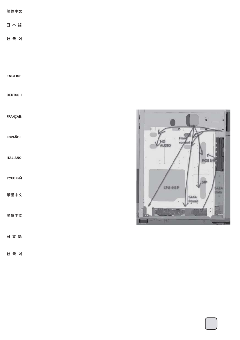
Optimal Thermal Performance Layout
(3) Tips For Cable Management
Please refer to the following diagrams
A. There are plenty of cable tie bridges behind the motherboard tray, which you can utilize to organize cables.
Bitte beachten Sie folgende Abbildungen
A.Hinter der Motherboard-Halterung finden Sie reichlich Kabelhalter, mit denen Sie die Kabel sauber
verlegen können.
Veuillez vous reporter aux schémas suivants
A. Il y a plein d'accroches-câbles disponible derrière le support de la carte mère que vous pouvez
utiliser pour organiser votre câblage.
Por favor, consulte los diagramas siguientes
A. Existen muchas bridas para cables tras la bandeja de la placa base, que puede utilizar para
organizar los cables.
Fare riferimento alle figure che seguono
A. Vi sono numerosi punti, dietro al supporto scheda madre, che possono erre utilizzati per
l’organizzazione dei cavi.
Обращайтесь к следующим чертежам
A.За лотком системной платы имеется множество проушин для безопасного крепления кабелей.
你可以參考下面兩張圖範例做整線規畫
特別說明:
A. 背面有大量的理線凸橋,可以斟酌把線材固定其上。
你可以参考下面两张图范例做整线规画
特别说明:
A. 背面有大量的理线凸桥,可以斟酌把线材固定其上。
以下の図を参照してください
A. マザーボードトレイ背面には、ケーブル取り回しに利用できる多くのケーブルタイバンドブリッジがあります。
다음 다이어그램을 참조하십시오
A. 메인보드 트레이 뒷면에는 다수의 케이블 타이 브릿지가 존재하며, 케이블 정리하는데 용이 합니다.
28
Page 30

Optimal Thermal Performance Layout
(3) Tips For Cable Management
B. The illustration explains which cables the openings are designed for cable placements, the illustration are based on most
common motherboard designs.
C.There is less than 10mm gap between the front edge of motherboard tray and left side panel. The gap between the top of
the 5.25” drive tray and the top cover is also less than 10mm. These were designed as part of structure strengthening areas
and are not made for storing cables and connectors so please don’t use these small gaps for cable routing to avoid damage.
B. Die Abbildung erklärt, welche Öffnungen für welche Kabel gedacht sind. Die Kabelplatzierungen in der Abbildung basieren auf
den typischen Mainboard-Layouts.
C. Zwischen der Vorderkante der Motherboard-Halterung und der linken Seitenrand verbleiben weniger als 10 mm Platz. Die Lücke
zwischen dem Oberteil der 5,25-Zoll-Laufwerkhalterung und der oberen Abdeckung beträgt ebenfalls weniger als 10 mm. Diese
Bereiche wurden zur Verstärkung des Gehäuses vorgesehen, nicht jedoch zum Verstauen von Kabeln und Steckern.
Missbrauchen Sie diese schmalen Lücken daher nicht zur Kabelführung; andernfalls kann es zu Schäden kommen.
B. L’illustration suivante vous indique l'usage des différents orifices de sortie des câbles.
C.Il y a moins de 10mm entre le bord frontal du support de la carte mère et le panneau latéral gauche. L'espace entre le bord
supérieur du casier 5.25” et le panneau supérieur est également inférieur à 10mm. Ces espaces ont été conçus pour renforcer la structure du boîtier et ne sont pas dédiés pour
stocker des câbles et des connecteurs donc veuillez ne pas les utiliser pour éviter des dégâts.
B. La ilustración explica para qué cables están diseñados los agujeros.
C. Hay un espacio de menos de 10mm entre el extremo frontal de la bandeja de la placa base y el panel del lado izquierdo. El espacio entre la parte superior de la bandeja para
dispositivos de 5,25” y la cubierta superior es también de menos de 10mm. Fueron diseñados como fortalecimiento de partes de la estructura y no se diseñaron para almacenar
cables y conectores, luego por favor no use esos pequeños huecos para enrutar cables si quiere evitar daños.
B. L’illustrazione di seguito spiega come utilizzare le aperture disposte sul supporto scheda madre, dedicate in modo specifico ai cavi evidenziati.
C. Vi sono meno di 10mm tra il bordo frontale della scheda madre ed il pannello laterale sinistro. Il gap tra la parte superiore del drive tray da 5,25” è anch’esso inferiore ai 10mm.
Queste parti sono state progettate come rinforzo della struttura e non sono state pensate per disporvi cavi. Per evitare danneggiamenti non utilizzare quindi gli spazi sopracitati
per il cable management.
B. На рисунке показано, для каких кабелей предназначены отверстия Размещение кабелей на рисунке приведено с учетом конструкции большинства системных плат.
C. Зазор между передним краем кронштейна материнской платы и левой боковой панелью составляет менее 10 мм. Зазор между верхним краем отсека для 5,25-дюймовых
устройств и верхней крышкой также составляет менее 10 мм. Эти зазоры образуют структурные элементы жесткости корпуса и не предназначены для размещения кабелей
или разъемов, поэтому во избежание повреждений не следует использовать эти небольшие зазоры для прокладки кабелей.
B. 上圖表示主機板托盤開孔的用途,請您參考使用。
C. 主機板前折邊與左側板,光碟機架上緣與上蓋的間隙都不足10mm。請不要讓線材穿過這些地方,避免損壞。這些都是結構補強所必要的機構,請見諒。
B. 上图表示主机板托盘开孔的用途,请您参考使用。
C. 主机板前折边与左侧板,光驱架上缘与上盖的间隙都不足10mm。请不要让线材穿过这些地方,避免损坏。这些都是结构补强所必要的机构,请见谅。
B. 図には開口部が、どのケーブルのために設計されているかが示されています。
C. マザーボードトレイのフロント縁と左側パネルの間には10mm未満の間隙があります。5.25インチドライブトレイ上部と上部カバーの間の間隙も10mm未満です。
これらは構造強化エリアの一部として設計されており、ケーブルやコネクタ類を保存する目的はありません。それで損傷防止のため、ケーブル取り回しにこれらの小さな間隙
を使わないでください。
B. 그림에는 개구부가 어떠한 케이블을 위해 설계되었는지 나와 있습니다.
C. 메인보드 트레이 전면 가장자리와 왼쪽 사이드 패널 사이의 간격은 10mm 정도 있습니다. 5.25” 드라이브 트레이와 상부 커버의 간격도 약 10mm 정도
있습니다. 이 간격들은 케이스 구조보강을 위한 공간이며, 케이블 정리를 위한 공간이 아니므로 사용할 경우 손상이 발생할 수 있으므로 , 이 작은 간격에
케이블을 통과시키거나 정리하는 공간을 사용하지 않기를 권장합니다.
29
Page 31

Optimal Thermal Performance Layout
(3) Tips For Cable Management
D. If multiple hard drives are installed, we recommend using CP06 to ease cable routing.
D. Falls mehrere Festplatten installiert sind, empfehlen wir zur einfachen Kabelführung den CP06.
D. Si plusieurs disques durs sont installés, nous vous recommandons d'utiliser CP06 pour un
acheminement de câble facile.
D. Si se instalan varios discos duros, le recomendamos usar el CP06 para enrutar los cables con facilidad.
D. Se sono installati più dischi rigidi, si raccomanda di usare CP06 per facilitare il cablaggio dei cavi.
D. Если устанавливается несколько жестких дисков, мы рекомендуем использовать корпус CP06
для облегчения прокладки кабелей.
D. 如果有需要在主硬碟架安裝多顆硬碟時,我們建議您選購銀欣CP06線材幫助理線。
D. 如果有需要在主硬盘架安装多颗硬盘时,我们建议您选购银欣CP06线材帮助理线。
D. 複数のハードディスクが設置されるならば、我々はケーブル・ルーティングを容易にするためにCP06を使うことを勧めます。
D. 여러 개의 드라이블가 설치된 경우, CP06을 사용하여 케이블 라우팅을 간편하게 할 것을 권장합니다.
Optimal Thermal Performance Layout
(4) Fan Speed Adjustment
FT04’s Air Penetrator fans are speed adjustable between 500rpm~2000rpm. The speeds are designed for silent or performance usage. 180mm fan switch guide: “L” indicates low
speed state and “H” indicates high speed state.
Air Penetrator-Lüfter FT04 mit einstellbarer Geschwindigkeit: 500 bis 2000 U/min. Die Geschwindigkeiten dienen einem geräuscharmen oder besonders leistungsstarken Betrieb.
Anleitung zum Schalter des 180-mm-Lüfters: “L” zeigt eine langsame Geschwindigkeit, “H” eine hohe Geschwindigkeit an.
La vitesse des ventilateurs FT04 Air Penetrator est réglable entre 600rpm, 900rpm ou 1200rpm. Les vitesses ont été conçues pour une utilisation silencieuse et performante. Guide
de changement de ventilateur de 180 mm : “ L ” indique un état de vitesse lente, la position du milieu indique un état de vitesse moyenne, “ H ” indique un état de vitesse rapide.
Los ventiladores Air Penetrator FT04 tienen una velocidad ajustable entre 500rpm~2000rpm. Las velocidades están diseñadas para modo silencioso ó de alto rendimiento.
Guía para el interruptor del ventilador de 180mm: “L” indica estado de baja velocidad y “H” indica estado de alta velocidad
La velocità delle ventole Air Penetrator di FT04 può essere regolata tra 600 rpm, 900 rpm e 1200 rpm.Le velocità sono state progettate per un uso in silenziosità o per le prestazioni.
Guida all’interruttore ventola 180 mm: “L” indica lo stato di bassa velocità, la posizione centrale indica lo stato di velocità media, “H” indica lo stato di alta velocità.
Скорость вращения вентиляторов Air Penetrator в корпусе FT04 можно изменять: 600 об/мин., 900 об/мин. или 1200 об/мин.Скорость вращения определяет бесшумный или
высокопроизводительный режим работы.Указатель переключателя 180-мм вентилятора: "L" означает низкую скорость вращения, среднее положение среднюю скорость,
"H" - высокую скорость вращения.
FT04的180mm穿甲彈風扇為可於500rpm ~ 2000rpm之間無段調速風扇。180風扇無段調速旋鈕開關說明圖: 往"L"方向轉動代表風扇轉速越低(最低500rpm),往"H"方向轉動代表風扇
轉速越高(最高2000rpm)。
FT04的180mm穿甲弹风扇为可于500rpm ~ 2000rpm之间无段调速风扇。180风扇无段调速旋钮开关说明图: 往"L"方向转动代表风扇转速越低(最低500rpm),往"H"方向转动代表风扇
转速越高(最高2000rpm)。
FT04の空の侵入者ファンは、600rpm、900rpmまたは1200rpmの間で可調速度です。速度は、無言であるかパフォーマンス使用のために設計されます。180mmは、スイッチ・ガイドに
風を送ります:「L」、と、低速州(中程度の速度州のための中央の位置)は示します。「H」は、高速州を示します。
FT04의 Air Penetrator 팬은 600rpm, 900rpm 또는 1200rpm으로 속도를 조정할 수 있습니다.저소음 또는 성능 용도에 맞출 수 있도록 여러
속도가 설계된 것입니다. 180mm 팬 스위치 가이드: “L”은 저속 상태를 가리키고 중간 속도 상태는 중간 위치에 놓이고 “H”는 고속 상태를
가리킵니다.
30
Page 32

Optimal Thermal Performance Layout
(5) Fan Replacement
SilverStone also has three models of 180mm fans for sale separately for replacement or upgrade
SilverStone bietet zudem drei Modelle der 180 mm-Lüfter zum separaten Verkauf; mit diesen können Sie Ihr System aufrüsten oder alte Lüfter ersetzen
SilverStone vend aussi trois modèles de ventilateur de 180mm pour le remplacement ou une amélioration.
SilverStone también tiene tres modelos de 180mm a la venta por separado como reemplazo ó mejora:
Silverstone ha in catalogo 3 differenti modelli di ventole da 180mm, utilizzabili come sostituzione od aggiornamento.
Кроме того, для замены или апгрейда компания "SilverStone" отдельно продает три модели 180-мм вентиляторов:
銀欣同時提供另外三款零售180mm風扇做為汰換或升級的選擇,我們認為風流量不足以代表整體散熱效能,在大部分的狀況下,穿甲彈的流場對FT04而言,是最有利的。
银欣同时提供另外三款零售180mm风扇做为汰换或升级的选择,我们认为风流量不足以代表整体散热效能,在大部分的状况下,穿甲弹的流场对FT04而言,是最有利的。
シルバーストーンはまた、交換やアップグレードのために別売の180mmの3つのモデルを用意しています:
SilverStone에서는 팬을 업그레이드나 교체를 위해 별도로 구매 가능한 3가지 종류의 180mm팬을 제공합니다:
Upgrade And Maintenance
(1) Fan filter removal guide
FT04’s positive air pressure design is an effective configuration that will reduce
dust buildup inside the case. Small air particles or lint will accumulate over time
on intake filters instead of on the components inside the case. To maintain
FT04’s excellent cooling performance for years to come, we recommend to
clean all fan filters regularly every three months or half a year (depending on
your environment). Below are steps to remove fan filters.
Das vorteilhafte Luftdruckdesign des FT04 ist eine effektive Konfiguration, die
Staubablagerungen innerhalb des Gehäuses vermindert. Im Laufe der Zeit
sammeln sich kleine Partikel und Fusseln an den Luftzufuhrfiltern, anstatt an den
Komponenten im Gehäuseinneren, an. Sie können eine jahrelange optimale
Kühlleistung des FT04 gewährleisten, indem Sie alle Lüfterfilter regelmäßig alle
drei bis sechs Monate reinigen (je nach Umgebungsbedingungen). Nachstehend
finden Sie die Schritte zur Entfernung der Lüfterfilter.
La conception à pression d'air positive du FT04 est une configuration efficace permettant de réduire l'accumulation de la poussière dans le boîtier. De petites particules d'air ou de
peluche vont s'accumuler avec le temps sur les filtres d'aspiration, et non sur les composants à l'intérieur du boîtier. Pour conserver les excellentes performances de refroidissement
du FT04 au fil des ans, nous vous recommandons de nettoyer l'ensemble des filtres des ventilateurs, tous les trois ou six mois (selon votre environnement). Vous trouverez ci-dessous
les étapes vous expliquant comment retirer les filtres des ventilateurs.
El diseño de presión de aire positiva de la FT04 es una configuración efectiva que reducirá la acumulación de polvo dentro de la carcasa. Pequeñas partículas de polvo ó pelusa se
irán acumularán con el transcurso del tiempo en los filtros de entrada en lugar de en los componentes del interior de la carcasa. Para mantener la excelente capacidad de
refrigeración de la FT04 en años venideros, le recomendamos que limpie con regularidad todos los filtros de los ventiladores cada tres meses ó seis meses
(dependiendo de dónde viva). A continuación están los pasos para quitar los filtros de los ventiladores.
Il design a pressione positiva di FT04 riduce considerevolmente gli accumuli di polvere all’interno del case. Le piccole particelle si accumulano infatti sui filtri invece che sui componenti
interni. Per mantenere le eccellenti prestazioni di raffreddamento di FT04 negli anni a venire vi raccomandiamo di procedere ad una regolare pulizia dei filtri
(con cadenza trimestrale o semestrale dipendentemente dall’ambiente un cui è disposto il sistema). Di seguito i passi per la rimozione dei filtri.
31
Page 33

Конструкция корпуса FT04 обеспечивает избыточное давление воздуха и, таким образом, имеет эффективную конфигурацию, препятствующую скоплению пыли внутри
корпуса. Небольшие частицы и волокна, содержащиеся в воздухе, со временем будут скапливаться на впускных фильтрах, а не на компонентах, находящихся внутри
корпуса. Для поддержания превосходного охлаждения компонентов в корпусе FT04 в течение многих
раз в 3 месяца или раз в полгода (в зависимости от условий окружающей среды). Ниже приведена процедура для удаления фильтров вентиляторов.
FT04的正壓差搭配濾網方式是經的起時間考驗最有效的防塵方式。在使用相當長一段時間後,棉屑灰塵或其他可能妨礙散熱效能的小異物只會卡在濾網,而不是電腦內的元件上面。
我們重視的散熱效能,是在您使用電腦長達2~3年後還能維持與全新的無異。為了維持這種散熱效能您只需要定期清理濾網,而不是電腦裡面的元件。
視環境而定,我們建議您每6個月~1年必須清理濾網,以下是濾網的拆卸步驟。
FT04的正压差搭配滤网方式是经的起时间考验最有效的防尘方式。在使用相当长一段时间后,棉屑灰尘或其它可能妨碍散热效能的小异物只会卡在滤网,而不是计算机内的组件上面。
我们重视的散热效能,是在您使用计算机长达2~3年后还能维持与全新的无异。为了维持这种散热效能您只需要定期清理滤网,而不是计算机里面的组件。
视环境而定,我们建议您每6个月~1年必须清理滤网,以下是滤网的拆卸步骤。
FT04の正圧設計は、ケース内のホコリの蓄積を減少させる有効な構造です。時と共に空気中の微粒子または糸くずはケース内のコンポーネト上の代わりに取入れ口フィルタに溜
まります。この先何年もの間FT04の素晴らしい冷却性能を維持するには、全てのファンを3ヶ月ないしは半年(環境に依存) ごとに規則的に清掃するようお勧めします。以下は、
ファンフィルタを取り外す手順です。
FT04의 양압 디자인은 케이스 내부에 먼지가 싸이는 것을 방지 하기 위한 효과적인 디자인입니다. 작은 분진이나 먼지는 케이스 내부에 있는필터에 시간에 따라
쌓이게 됩니다. FT04의 우수한 냉각 성능을 계속 유지하기 위헤서 매 3개월 혹은 6개월(사용환경에 따라)마다 필터 청소를권장합니다. 다음의 필터 제거 과정을
참고하세요.
Open front door and remove the fan filter. Remove top filter by pulling it rearwards.
лет рекомендуется регулярно очищать все фильтры вентиляторов:
Upgrade And Maintenance
(2) Cleaning the fan filter
FT04 uses finer air filters that offer higher airflow ratio. They have the same filtering ability but with increased airflow
percentage from 65% to 90% compared to previous generation of nylon filters. However, these finer filters are not as
durable so please note of the following precautions when cleaning them.
Methods of cleaning:
1. Cleaning with a soft brush
Fan filter can be cleaned using a soft brush. Please DO NOT use a steel brush as it will cause damage to the filter. We recommend you to wear a respirator when cleaning the fan
filter to prevent inhaling unnecessary dust.
2. Cleaning using a vacuum cleaner
If it is difficult to remove the fan filter, cleaning with a vacuum cleaner is the best method. To prevent the vacuum cleaner from damaging the fan blades, please secure them before
cleaning.
3. Cleaning with water
Rinsing with water is the cleanest way to cleaning the fan filter. After rinsing the fan filter with water, dry the filter at a well ventilated area out of direct sunlight. DO NOT use a blow
dryer, oven or microwave oven...etc to dry the fan filter. This will damage the fan filter. If you feel the drying process is too time-consuming, we recommend you to keep a spare set
of fan filter as backups. DO NOT reinstall the fan filter before it is fully dry, it may cause shorts or damage to other computer components.
Note: As the fan filter material is very thin, please keep it away from any Velcro material as they will cause damages to fan filter.
Purchasing additional fan filter
To purchase a retail fan filter as an upgrade or replacement in the event of loss, damage or simply as a backup, you can search on our website for the nearest resellers or
distributor: http://www.silverstonetek.com/wheretobuy_all.php
Beim FT04 werden feinere Luftfilter eingesetzt, die einen höheren Luftdurchsatz ermöglichen. Diese weisen ein identisches Filtervermögen auf, jedoch mit einem im Vergleich zu älteren
Nylon-Filtern um 65 – 90 % gesteigerten Luftdurchsatz. Allerdings sind diese feineren Filter etwas weniger robust; beachten Sie daher die folgenden Vorsichtsmaßnahmen bei der
Reinigung.
Reinigungsmethoden:
1. Reinigung mit einer weichen Bürste
Der Lüfterfilter kann mit einer weichen Bürste gereinigt werden. Verwenden Sie KEINE Stahlbürsten; diese beschädigen den Filter. Wir empfehlen, bei der Reinigung der Lüfterfilter einen
Atemschutz zu tragen, damit Sie nicht unnötig viel Staub einatmen.
2. Reinigung mit einem Staubsauger
Falls sich der Lüfterfilter nur schwierig entfernen lassen sollte, empfiehlt sich die Reinigung mit einem Staubsauger. Damit die Lüfterflügel nicht durch den Staubsauger beschädigt werden,
fixieren und schützen Sie diese vor der Reinigung.
3. Reinigung mit Wasser
Das Spülen mit Wasser ist der sauberste Weg zur Reinigung eines Lüfterfilters. Nachdem Sie den Lüfterfilter gründlich mit Wasser gespült haben, lassen Sie den Filter an einer gut
belüfteten Stelle trocknen, nicht jedoch im prallen Sonnenlicht.
Versuchen Sie NICHT, den Lüfterfilter mit einem Haartrockner, Ofen oder gar in der Mikrowelle zu trocknen. Andernfalls wird der Lüfterfilter beschädigt. Falls Ihnen das Trocknen zu lange
dauert, sollten Sie sich einen zweiten Satz Lüfterfilter als Reserve anschaffen. Installieren Sie Lüfterfilter NICHT, bevor diese vollständig getrocknet sind; andernfalls kann es zu
Kurzschlüssen und Beschädigungen an anderen Computerkomponenten kommen.
Hinweis: Da das Lüfterfiltermaterial sehr dünn ist, halten Sie es unbedingt von Klettverschlüssen fern; andernfalls drohen schwere Beschädigungen. Zusätzliche Lüfterfilter erwerben
Wenn Sie einen Lüfterfilter als Zusatz, zum Austausch bei Verlust oder Beschädigung oder einfach als Reserve erwerben möchten, suchen Sie einfach auf unseren Internetseiten nach
einem Händler oder Distributor in Ihrer Nähe: http://www.silverstonetek.com/wheretobuy_all.php
32
Page 34

FT04 utilise des filtres à air plus fins qui offrent un taux de débit d’air plus élevé. Ils présentent la même capacité de filtrage mais ont un pourcentage de débit d’air accru de 65% à 90%
par rapport à la génération précédente de filtres en nylon. Cependant, ces filtres plus fins ne sont pas aussi durables, veuillez donc prendre note des précautions de nettoyage suivantes
lorsque vous les nettoyez.
Méthodes de nettoyage:
1. Nettoyage avec une brosse douce
Le filtre du ventilateur peut être nettoyé avec une brosse douce. N’UTILISEZ PAS de brosse en métal car elle risquerait d’endommager le filtre. Nous vous recommandons de porter un
masque lors du nettoyage du filtre du ventilateur pour éviter d’inhaler de la poussière inutilement.
2. Nettoyage en utilisant un aspirateur
S’il est difficile de retirer le filtre du ventilateur, le nettoyage avec un aspirateur est la meilleure méthode. Pour éviter que l’aspirateur n’endommage les pales du ventilateur, veuillez
bien les fixer avant le nettoyage.
3. Nettoyage à l’eau
Rincer à l’eau est la façon la plus propre de nettoyer le filtre du ventilateur. Après avoir rincé le filtre du ventilateur à l’eau, séchez le filtre à un endroit bien ventilé, éloigné des rayons
directs du soleil.
N’UTILISEZ PAS de sèche cheveux, de four ou de four à micro-ondes ...etc. pour sécher le filtre du ventilateur. Ceci endommagerait le filtre du ventilateur. Si vous estimez que le
processus de séchage prend trop de temps, nous vous recommandons de conserver un ensemble de filtres du ventilateur de rechange. NE reinstallez PAS le filtre du ventilateur
avant qu’il ne soit totalement sec, car ceci pourrait causer des courts-circuits ou endommager d’autres composants de l’ordinateur.
Note: Etant donné que le matériau du filtre du ventilateur est très fin, veuillez le conserver à l’abri des matériaux en Velcro car ils pourraient endommager le filtre du ventilateur.
Acheter un filtre du ventilateur supplémentaire
Pour acheter un filtre du ventilateur au détail comme pour l’améliorer ou pour le remplacer en caisson de perte, de dommage ou simplement en rechange, vous pouvez rechercher sur
notre site Internet pour connaître les revendeurs ou les distributeurs les plus proches de chez vous: http://www.silverstonetek.com/wheretobuy_all.php
La FT04 usa filtros de aire más finos que ofrecen una mejor proporción de flujo de aire. Tienen la misma capacidad de filtrado pero con un porcentaje de flujo de aire que aumenta de
65% a 90% si se compara con la generación previa de filtros de nylon. Sin embargo, estos filtros más finos no son tan resistentes, luego por favor tenga en cuenta las siguientes
precauciones cuando los limpie.
Métodos de limpieza:
1. Limpieza con un cepillo suave
El filtro del ventilador se puede limpiar usando un cepillo suave. Por favor NO USE un cepillo de acero ya que
causará daño al filtro. Le recomendamos que se ponga una mascarilla cuando limpie el filtro del ventilador para
evitar inhalar polvo innecesariamente.
2. Limpieza con un aspirador
Es difícil quitar el filtro del ventilador, limpiarlo con un aspirador es el mejor método. Para evitar que el aspirador dañe las aspas del ventilador, por favor fíjelas antes de limpiar.
3. Limpieza con agua
Limpiar con agua es el mejor modo de limpiar el filtro del ventilador. Tras limpiar el filtro con agua, seque el filtro en una zona bien ventilada apartada de la luz solar directa.
NO USE un secador, microondas u horno, etc. para secar el filtro de ventilador. Esto dañará el filtro del ventilador.
Si piensa que el proceso de secado es un proceso que requiere demasiado tiempo, le recomendamos que conserve un juego de filtros como recambios.
NO INSTALE el filtro para ventilador antes de que esté seco del todo, podría provocar cortocircuitos o daño a otros componentes del ordenador.
Nota: ya que el material del filtro es muy fino, por favor aléjelo de cualquier material de velcro ya que provocaría daño al filtro del ventilador.
Comprar filtros adicionales para ventilador
Para comprar un filtro para ventilador como mejora o reemplazo en caso de pérdida, daño o simplemente como recambio, puede buscar en nuestra página web para encontrar el
distribuidor o vendedor autorizado más cercano: http://www.silverstonetek.com/wheretobuy_all.php
L'FT04 utilizza filtri per l'aria più sottili che offrono un maggiore rapporto di flusso d'aria. Hanno la stessa capacità di filtraggio, ma con una maggiore percentuale di flusso d'aria dal
65% al 90% rispetto alla precedente generazione di filtri in nylon. Tuttavia, questi filtri più sottili non hanno una grande durata. Si prega pertanto di notare le seguenti precauzioni
quando li si pulisce.
Metodi di pulizia:
1. Pulizia con una spazzola morbida
Il filtro della ventola può essere pulito con una spazzola morbida. NON utilizzare una spazzola in acciaio per evitare di danneggiare il filtro. Si consiglia di indossare un respiratore
durante la pulizia del filtro della ventola per evitare l'inalazione di polvere.
2. Pulizia con un aspirapolvere
Se è difficile rimuovere il filtro della ventola, il metodo migliore è utilizzare un aspirapolvere. Per evitare che l'aspirapolvere danneggi le lame della ventola, fissarle prima della pulizia.
3. Pulizia con acqua
Il metodo migliore per pulire il filtro della ventola è risciacquandolo con acqua. Dopo aver risciacquato il filtro della ventola, asciugarlo in un ambiente ben ventilato lontano dalla luce
solare diretta.
NON utilizzare asciugacapelli, forno o forno a microonde, ecc. per asciugare il filtro della ventola in quanto danneggiano il filtro della ventola. Se l'asciugatura dura troppo a lungo, si
consiglia di tenere a portata di mano un filtro di ricambio. NON reinstallare il filtro della ventola prima che sia completamente asciugato in quanto potrebbe causare cortocircuito o
danni ad altri componenti del computer.
Nota: Poiché il materiale del filtro della ventola è estremamente sottile, tenerlo lontano dal materiale in velcro per evitare di danneggiare il filtro della ventola.
Acquisto di un altro filtro della ventola
Per acquistare un filtro della ventola al dettaglio per la sostituzione in caso di perdita, danni o semplicemente uno di riserva, è possibile cercare sul nostro sito web i rivenditori o
distributori più vicini: http://www.silverstonetek.com/wheretobuy_all.php
В корпусе SG09 применяются мелкопористые фильтры с увеличенным пропускной способностью воздушного потока. При одинаковой эффективности фильтрации их
пропускная способность по сравнению с нейлоновыми фильтрами предыдущего поколения увеличилась с 65% до 90%. Однако новые фильтры менее прочные, поэтому при
их чистке следует соблюдать следующие меры предосторожности.
Способы чистки
1. Чистка мягкой щеткой
Фильтр допускается чистить щеткой с мягкой щетиной. ЗАПРЕЩАЕТСЯ применять щетки с металлической щетиной, так как это приведет к повреждению фильтра. Во
избежание вдыхания пыли в ходе чистки фильтра рекомендуется надевать респиратор.
2. Чистка пылесосом
Если снять фильтр вентилятора по каким-либо причинам затруднительно, то в этом случае для чистки рекомендуется использовать пылесос. Во избежание повреждения
пылесосом крыльчатки вентилятора перед началом чистки их следует зафиксировать.
3. Чистка водой
Самым эффективным методом чистки фильтра вентилятора является чистка водой. После промывки фильтра в воде его необходимо просушить в хорошо вентилируемом
помещении, не подвергая воздействию прямых солнечных лучей.
Для просушки фильтра запрещено применять фен, духовку, микроволновую печь и т.п. Это приведет к повреждению фильтра.
Если Вы считаете, что процесс сушки фильтра требует слишком много времени, следует приобрести запасной комплект фильтров.
ЗАПРЕЩАЕТСЯ устанавливать фильтр до его полного высыхания, в противном случае это может привести к короткому замыканию или повреждению других компонентов
компьютера. Примечание. Так как материал фильтра вентилятора очень тонкий, не держите их рядом с липучками типа Velcro. Липучки могут повредить фильтр.
Приобретение дополнительного фильтра вентилятора
На нашем сайте Вы найдете ближайшего торгового посредника или дистрибьютора, у которого можно приобрести фильтр вентилятора для замены в случае потери или
повреждения старого фильтра, или про запас. http://www.silverstonetek.com/wheretobuy_all.php
33
Page 35
FT04採用更高通風性的超薄濾網,在保持相同的過濾能力之下,通風比例由之前尼龍紗網的65%提升到90%。但是這種濾網並不比以前的尼龍濾網堅固。以下是清潔上的注意事項:
清潔方法:
1.使用軟毛刷清理
濾網可以使用軟質毛刷進行清理。千萬不可以使用鋼刷,以免造成濾網損毀。建議在清理的時候戴口罩,以免吸入有害灰塵。
2.使用吸塵器清理
使用吸塵器清理是最方便的。如果你不方便將濾網拆下,請注意先固定住風扇之扇葉,再以吸塵器進行清理。避免吸塵器吸力過大,損壞風扇。
3.用水沖洗
通常來說,用水沖洗可將濾網清理的最乾淨。沖洗完,請將濾網放置在通風良好之陰暗處晾乾,避免陽光照射。嚴禁使用吹風機、烤箱或微波爐等方式對濾網進行加熱,
以免造成濾網損毀。如果您覺得濾網晾乾的時間過久,建議您可以準備一份濾網做替換。如果濾網尚未晾乾,在濕濕的狀態下裝回機殼使用,有可能會造成您電腦元件的短路以
及損壞,請務必避免。
注意事項:
因為纖維比較細,在使用過程須確保遠離魔鬼氈,以避免鈎黏住。溝黏住可能導致濾網的破損
添購濾網
如果您不慎遺失、人為損壞或只是想要多購買濾網備用。請與我們的經銷點聯絡進行購買。
請上SilverStone網站查詢各區域經銷 http://www.silverstonetek.com.tw/wheretobuy_all.php?area=tw
T04采用更高通风性的超薄滤网,在保持相同的过滤能力之下,通风比例由之前尼龙纱网的65%提升到90%。但是这种滤网并不比以前的尼龙滤网坚固。以下是清洁上的注意事项:
清洁方法:
1.使用软毛刷清理
滤网可以使用软质毛刷进行清理。千万不可以使用钢刷,以免造成滤网损毁。建议在清理的时候戴口罩,以免吸入有害灰尘
2.使用吸尘器清理
使用吸尘器清理是最方便的。如果你不方便将滤网拆下,请注意先固定住风扇之扇叶,再以吸尘器进行清理。避免吸尘器吸力过大,损坏风扇。
3.用水冲洗
通常来说,用水冲洗可将滤网清理的最干净。冲洗完,请将滤网放置在通风良好之阴暗处晾干,避免阳光照射。严禁使用吹风机、烤箱或微波炉等方式对滤网进行加热,以
免造成滤网损毁。如果您觉得滤网晾干的时间过久,建议您可以准备一份滤网做替换。如果滤网尚未晾干,在湿湿的状态下装回机壳使用,有可能会造成您计算机组件的短路以
及损坏,请务必避免。
注意事项:
因为纤维比较细,在使用过程须确保远离魔鬼毡,以避免钩黏住。沟黏住可能导致滤网的破损
添购滤网
如果您不慎遗失、人为损坏或只是想要多购买滤网备用。请与我们的经销点联络进行购买。
请上SilverStone网站查询各区域经销 http://www.silverstonetek.com.tw/wheretobuy_all.php?area=tw
FT04は、より高い気流比率を提供するより優れたエアフィルタが使用されています。これは、前世代のナイロン・フィルタと比較して65%から90%まで増加した気流比率で同一の
フィルタリング能力を発揮します。しかし、これらの高性能フィルタは耐久性はさほどよくないので、お手入れの際は以下の点にご注意ください。
清掃方法:
1. ソフトブラシでの清掃
ファン・フィルタは、ソフトブラシを使って清掃できます。スチールブラシはフィルタに損傷を与えるので使わないでください。ファン・フィルタ清掃の際は、塵を吸い込ま
ないよう、マスクの着用をお勧めいたします。
2.掃除機を使った清掃
ファン・フィルタの取り外しが難しい場合、掃除機での清掃が最善の方法です。掃除機がファン・ブレードに損害を与えるのを予防するために、清掃前に固定してください。
3.水による清掃
水ですすぐのが、ファン・フィルタを最もきれいにする方法です。ファン・フィルタを水で洗浄した後、直射日光の差さない換気が良い場所でフィルタを乾燥させてください。
ファン・フィルタを乾燥させるのに、ヘアドライヤー、オーブンまたは電子レンジなどを使わないでください。これは、ファン・フィルタに損傷を与えます。乾燥過程に時間
がかかり過ぎると感じる場合、バックアップとしてファン・フィルタの予備セットを持つようお勧めいたします。ファン・フィルタは完全に乾く前に、再インストールしない
でください。これは他のコンピュータコンポーネントにショートまたは損傷を引き起こす場合があります。
注記:ファン・フィルタ材料は非常に薄いので、いずれのマジックテープ素材に近づけないでください。それはファン・フィルタに損傷をもたらします。
追加ファン・フィルタの購入
アップグレードまたは損失の場合の交換用、または単にバックアップとして小売ファン・フィルタを購入するには、最寄りの小売業者または卸売業者を下記の当社ウェブサ
イトから検索できます。http://www.silverstonetek.com/wheretobuy_all.php
FT04는 공기 흐름 비가 매우 높은 미세한 공기 필터를 사용합니다. 이 필터는 이전 세대의 나일론 필터와 비교할 때 여과 성능은 동일하지만 공기 흐름
비는 65%에서 90%로 증가했습니다. 그러나 미세한 필터는 내구성이 그만큼 좋지 않기 때문에 필터 청소 시 다음과 같은 주의사항에 유의하십시오.
청소 방법:
1. 부드러운 솔을 사용한 청소
팬 필터는 부드러운 솔을 사용하여 청소할 수 있습니다. 필터를 손상시키는 철로 된 솔은 사용하지 마십시오. 팬 필터를 청소할 때는 불필요한 먼지를 들이마시지
않도록 마스크를 착용하는 게 좋습니다.
2. 진공 청소기를 사용한 청소
팬 필터를 분리하는 게 어려운 경우, 진공 청소기를 사용하여 청소하는 게 가장 좋은 방법입니다. 진공 청소기가 팬 블레이드를 손상시키지 않도록 하려면,
청소하기 전에 이를 고정하십시오.
3. 물을 사용한 청소
물로 헹구는 것이 팬 필터를 가장 깨끗하게 청소하는 방법입니다. 팬 필터를 물로 헹군 다음에는 직사 광선을 피해 통풍이 잘 되는 장소에서 필터를 말리십시오.
드라이어, 오븐 또는 전자 렌지 등을 사용하여 팬 필터를 말리지 마십시오. 그럴 경우 팬 필터가 손상됩니다.
말리는 데 시간이 너무 오래 걸린다고 생각되면 팬 필터 세트 하나를 여분으로 준비해두는 게 좋습니다. 팬 필터가 완전히 마르기 전에 제자리에 도로 장착하지
마십시오. 그럴 경우 단락이 발생하거나 다른 컴퓨터 구성부품을 손상시킬 수 있습니다.
참고: 팬 필터 소재는 매우 얇습니다. 벨크로 재질은 팬 필터를 손상시키므로 팬 필터 가까이 두지 마십시오.
추가 팬 필터 구입
팬 필터가 분실 또는 손상되어 소매로 팬 필터를 구입하거나 단순히 여분으로 구입하려는 경우, 당사의 웹사이트에서 가까운 판매점을 검색할 수 있습니다.
http://www.silverstonetek.com/wheretobuy_all.php
34
Page 36
Upgrade And Maintenance
(2) ClearCMOS
FT04 supports SST-CLEARCMOS installation on a designated part of the case, please see example below:
Das FT04 unterstützt die SST-CLEARCMOS-Installation an einem dazu vorgesehenen Teil des Gehäuses; bitte halten Sie sich an das nachstehende Beispiel:
Le FT04 est compatible avec l'installation du SST-CLEARCMOS dans une partie spéciale du boîtier, voici un exemple ci-dessous:
La FT04 acepta la instalación de SST-CLEARCMOS en una parte dedicada a ello en la carcasa, por favor vea el ejemplo siguiente:
FT04 supporta l’installazione, in una specifica zona del case, di SST-CLEARCMOS, come da esempio seguente:
В корпусе FT04 в специально отведенном месте может быть установлен разгонщик SST-CLEARCMOS, ниже приводится пример:
FT04支援SST-CLEARCMOS安裝在非佔用Slot卡槽的地方,請參考下圖:
FT04支持SST-CLEARCMOS安装在非占用Slot卡槽的地方,请参考下图:
FT04はケースの指定された部分でのSST-CLEARCMOSインストールに対応しています。下の例をご参照ください:
FT04는 SST-CLEARCMOS 설치는 아래 예와 같이 케이스에 지정된 부분에 설치합니다:
Upgrade And Maintenance
(3) Hot-swap
CP05 and CP05-SAS can be purchased separately if you wish to have hot-swap function. Please note the following:
A. If you need to swap hard drives while running an operating system (hot-swap), you need to make sure the SATA chipset (or motherboard southbridge) used to connect to hard
drives has proper support and driver to do so. For more information on how to setup your system for hot-swap hard drives, please refer to the video at this link:
http://www.youtube.com/watch?v=NoNiEMPnSEk
B. Once you have successfully set up hot-swap functionality in your system, we recommend using separate power cables for system drive and data drives. It is best to use hot-swap
function on data drives and connect system drive directly to SATA 15 Pin connector. (Ignore this if you are using CP05-SAS)
CP05 und CP05-SAS können separat erworben werden, falls Sie Hot-Swapping-Funktionalität wünschen. Bitte beachten Sie Folgendes:
A. Wenn Sie Festplatten im laufenden Betrieb austauschen müssen (Hot-Swapping), muss der SATA-Chipsatz (oder die Southbridge des Motherboards) diese Funktion unterstützen;
außerdem sind entsprechende Treiber erforderlich. Weitere Informationen zum Einrichten Ihres Systems mit Hot-Swapping-Festplatten finden Sie im folgenden Video:
http://www.youtube.com/watch?v=NoNiEMPnSEk
B. Sobald Sie die Hot-Swapping-Funktionalität erfolgreich in Ihrem System eingerichtet haben, empfehlen wir Ihnen den Einsatz separater Netzkabel für das Systemlaufwerk und die
Datenlaufwerke. Idealerweise sollten Sie die Hot-Swapping-Funktionalität bei Festplatten einrichten und das Systemlaufwerk direkt mit dem 15-poligen SATA-Anschluss verbinden.
(Ignorieren Sie dies beim CP05-SAS)
CP05 et CP05-SAS peuvent être achetés séparément si vous souhaitez avoir la fonction hot-swap. Veuillez noter ce qui suit :
A. Si vous avez besoin de changer de disque dur pendant que le système d'exploitation fonctionne (hot-swap), vous avez besoin d'être sur et certains que la puce SATA
(ou la puce southbridge de la carte mère) utilisé pour brancher le disque dur possède un bon support et un bon pilote pour cette fonctionnalité. Pour plus d'informations sur comment
configurer votre système pour utiliser les disques durs hot-swap, veuillez vous référer à la vidéo disponible à ce lien : http://www.youtube.com/watch?v=NoNiEMPnSEk
B. Une fois que vous aurez réglé la fonction hot-swap dans votre système, nous vous recommandons d'utiliser des câbles d'alimentation distincts pour le lecteur du système et pour
les lecteurs de données. Il est préférable d'utiliser la fonction hot-swap sur les lecteurs de données et de connecter le lecteur du système directement sur la broche du connecteur
SATA 15. (Ignorez ceci si vous utilisez CP05-SAS)
La CP05 y CP05-SAS se pueden comprar por separado si desea tener función de cambio en caliente.
Por favor, tenga en cuenta lo siguiente:
A. Si necesita cambiar sus discos duros mientras se ejecuta un sistema operativo (cambio en caliente), necesita asegurarse de que el chipset SATA (ó southbridge de la placa base)
usado para conectar los discos duros tiene los controladores y funcionalidad adecuados. Para más información sobre cómo configurar su sistema para cambiar en caliente los discos
duros, por favor consulte el video de este
vínculo: http://www.youtube.com/watch?v=NoNiEMPnSEk
B. Una vez haya conseguido configurar la función de cambio en caliente de su sistema, le recomendamos usar cables de potencia separados para los discos del sistema y de datos.
Es mejor usar la función de cambio en caliente con discos de datos y conectar el disco del sistema directamente a un conector SATA de 15 pines.
(Ignore esto si está usando el CP05-SAS)
35
Page 37

CP05 e CP05-SAS possono essere acquistati separatamente se si vuole avere la funzione hot-swap. Prendere nota di quanto segue:
A. Se avete bisogno di effettuare un hot-swap mentre è attivo il sistema operativo, dovete essere sicuri che il chipset di controllo del SATA (od il southbridge della scheda madre)
siano dotati del supporto e dei driver specifici. Per maggiori informazioni su come configurare il vostro sistema per hard disk hot-swap, fate riferimento al video presente presso il
seguente link: http://www.youtube.com/watch?v=NoNiEMPnSEk
B. Dopo aver impostato correttamente sul sistema la funzione hot-swap, si raccomanda di usare cavi d’alimentazione separati per le unità di sistema e le unità di dati. È meglio
usare la funzione hot-swap su dischi di dati e collegare le unità di sistema direttamente al connettore SATA 15 pin. (Ignorare queste istruzioni se si usa CP05-SAS)
Если вы хотите пользоваться функцией горячего подключения, можно приобрести отдельно корпуса CP05 и CP05-SAS. Обратите внимание на следующее:
A. Если вам надо подключить жесткие диски при запущенной операционной системе (горячее подключение), убедитесь, что чипсет SATA (или южный мост материнской
платы), используемый для подключения жестких дисков, поддерживает эту возможность, и нужный драйвер
настроить систему для горячего подключения жестких дисков, вы найдете в видеоролике по ссылке: http://www.youtube.com/watch?v=NoNiEMPnSEk
B. После настройки функции «горячего» подключения компонентов системы рекомендуется использовать отдельные кабели питания для системного диска и дисков
данных. Лучше всего использовать функцию горячего подключения с дисками данных, а системный диск подключить
(Это не относится к корпусу CP05-SAS)
如果您有需要SATA hot-swap功能,可以額外選購 CP05或CP05 SAS模組。您可以額外添購2組。但請您注意以下幾點:
A.如果有需要在開機的狀態下,插拔硬碟(即熱插拔)。請先確認您的SATA控制晶片有支援熱插拔,並已正確的驅動。關於SATA熱插拔的啟動請參考以下影片:
http://www.youtube.com/watch?v=NoNiEMPnSEk
B.如果您已經成功使用熱插拔,我們建議您將系統硬碟與資料硬碟的硬碟接線分開。最好是資料硬碟才使用熱插拔模組,而系統硬碟直接使用 Power的SATA 15 Pin接線。
(如果您使用的是CP05-SAS模組,可直接忽略本點)
如果您有需要SATA hot-swap功能,可以额外选购 CP05或CP05 SAS模块。您可以额外添购2组。但请您注意以下几点:
A.如果有需要在开机的状态下,插拔硬盘(即热插拔)。请先确认您的SATA控制芯片有支持热插拔,并已正确的驱动。关于SATA热插拔的启动请参考以下影片:
http://www.youtube.com/watch?v=NoNiEMPnSEk
B.如果您已经成功使用热插拔,我们建议您将系统硬盘与数据硬盘的硬盘接线分开。最好是数据硬盘才使用热插拔模块,而系统硬盘直接使用 Power的SATA 15 Pin接线。
(如果您使用的是CP05-SAS模块,可直接忽略本点)
あなたが熱い交換機能がありたいならば、CP05とCP05-SASは別に購入されることができます。以下に注意してください:
A. オペレーティングシステム稼働中にハードディスクドライブを交換する(ホットスワップ)必要がある場合、ハードディスクドライブ接続に使用されるSATAチップセット
(またはマザーボードのサウスブリッジ)およびドライバが正しく対応していることを確認してください。ご使用のシステムをハードディスクドライブのホットスワップ対応に設
定する方法については、下記リンクのビデオをご参照ください。http://www.youtube.com/watch?v=NoNiEMPnSEk
B. 一旦あなたがあなたのシステムで熱い交換機能をうまく準備するならば、我々はシステムドライブのために別々のパワーケーブルを使うことを勧めます、そして、データは
運転します。データ・ドライブに関して熱い交換機能を使用して、直接システムドライブをサタ15に接続することがコネクタにピンでとめることは、最高です。(
あなたがCP05-SASを使っているならば、これを無視してください)
핫스왑 기능을 사용하려면 CP05와 CP05-SAS를 별도로 구입할 수 있습니다. 다음에 주의하십시오:
A. 운영체제가 동작하는 중에 하드 드라이브를 스왑(핫스왑)핑 하려면, 메인보드 사우스브리지의 SATA 칩셋을 확인해, 드라이버가 하드 드라이브를 정상적으로
지원하는지 확인해야 합니다. 핫스와 하드 드라이브 장착에 필요한 보다 더 자세한 정보를 는 다음 링크를 참조하시기 바랍니다.
http://www.youtube.com/watch?v=NoNiEMPnSEk
B. 시스템이 핫스왑 기능을 성공적으로 설치한 경우 시스템 드라이브와 데이터 드라이브용 케이블을 별도로 사용할 것을 권장합니다. 핫스왑 기능은 데이터
드라이브에서 사용하고 시스템 드라이브는 SATA 15 핀 커넥터에 직접 연결하는 것이 가장 좋은 방법입니다.
(CP05-SAS를 사용한 경우 위의 지침을 무시하십시오)
установлен. Дополнительную информацию о том, как
непосредственно к 15-контактному разъему SATA.
Upgrade And Maintenance
(4) Front fan removal guide
ABCDAB
A. Remove both right and left side panels.
B. Open the front door and remove the fan filter.
C. Loosen screws holding the fan to remove it.
D. Loosen screws holding the fan speed switch, then route the switch through the hole on front panel. (Note: please use a small screwdriver for this)
E. To reinstall the fan, simply follow the steps in reverse
Downgrading to a 120mm fan:
A. Secure the fan using normal fan screws onto the transfer bracket that is included in FT04’s accessories box.
B. Use the short screw (#6-32) to screw the bracket onto the chassis.
A. Nehmen Sie rechte und linke Seitenwand ab.
B. Öffnen Sie die Frontklappe, entfernen Sie den Lüfterfilter.
C. Lösen Sie die Fixierschrauben des Lüfters, nehmen Sie den Lüfter heraus.
D. Lösen Sie die Schrauben des Lüftergeschwindigkeitsschalters; führen Sie den Schalter durch das Loch an der Frontblende.
(Hinweis: Bitte verwenden Sie dazu einen kleinen Schraubendreher)
E. Zum Wiedereinbau des Lüfters führen Sie die obigen Schritte einfach in umgekehrter Reihenfolge aus.
Downgrading to a 120mm fan
1. Fixieren Sie den Lüfter mit normalen Lüfterschrauben an der Halterung, die Sie im FT04-Zubehörkarton finden.
2. Fixieren Sie die Halterung mit der kurzen Schraube (6-32) am Gehäuse.
36
Page 38
A. Retirez les deux panneaux latéraux
B. Ouvrez la porte d’accès frontal et enlevez le filtre du ventilateur.
C. Desserrez les vis fixant le ventilateur pour le démonter
D. Dévissez les vis qui tiennent le commutateur de vitesse du ventilateur, puis placez le commutateur à travers le trou du panneau frontal.
(Note : Veuillez utiliser un petit tournevis pour ceci)
E. Pour réinstaller le ventilateur, veuillez simplement suivre les instructions en sens inverse.
Downgrading to a 120mm fan: (SG09-P47)
1. Fixez le ventilateur en utilisant une vis de ventilateur normale sur la console de transfert inclus dans la boîte d’accessoires de FT04.
2. Utilisez la vis courte (#6-32) pour visser la console sur la masse.
A. Quite los paneles izquierdo y derecho
B. Abra la puerta frontal, luego retire el filtro del ventilador.
C. Afloje los tornillos que sujetan el ventilador para quitarlo
D. Afloje los tornillos que sujetan el interruptor de velocidad del ventilador, luego enrute el interruptor a través del agujero del panel frontal.
(Nota: por favor use un destornillador pequeño para esto)
E. Para reinstalar el ventilador, tan sólo siga los pasos al revés.
Downgrading to a 120mm fan: (SG09-P47)
1. Fije el ventilador usando tornillos para ventilador normales en el bracket de transferencia que está incluido en la caja de accesorios de la FT04.
2. Use el tornillo corto (#6-32) para atornillar el bracket al chasis.
A. Rimuovere entrambi i pannelli laterali
B. Aprire il portello frontale, quindi rimuovere il filtro della ventola.
C. Allentare le viti della ventola per rimuoverla.
D. Allentare le viti che fissano l’interruttore di velocità della ventola, quindi infilare l'interruttore attraverso il foro sul pannello frontale.
(Nota: usare un piccolo cacciavite per eseguire questa operazione)
E. Per reinstallare la ventola, seguire i passi precedenti al contrario.
Downgrading to a 120mm fan: (SG09-P47)
1. Fissare la ventola utilizzando viti normali sulla staffa di trasferimento in dotazione nella scatola degli accessori dell'FT04.
2. Utilizzare la vite corta (#6-32) per avvitare la staffa sul telaio.
A. Снимите левую и правую боковые панели.
B. Откройте переднюю дверцу, затем снимите фильтр вентилятора.
C. Отвинтите винты, крепящие вентилятор, и снимите его.
D. Отверните винты крепления переключателя скорости вентилятора и пропустите переключатель через отверстие в передней панели.
(Примечание: используйте для этого маленькую отвертку)
E. Чтобы установить вентилятор на место, просто выполните указанные действия в обратном порядке.
Downgrading to a 120mm fan: (SG09-P47)
1. Закрепите вентилятор стандартными винтами на переходном кронштейне, входящим в комплект дополнительных принадлежностей корпуса FT04.
2. Закрепите кронштейн на корпусе с помощью короткого винта (№ 6–32).
A. 已經拆卸左右板的狀態。
B. 開門,移除濾網。
C. 卸除固定風扇的螺絲,卸除風扇。
D. 卸除固定轉速切換開關的螺絲,將轉速切換開關由前面板的洞穿出機殼。(溫馨小提醒:這裡需使用更小的螺絲起子進行拆裝。)
E. 依照相反的順序安裝回去。
降級安裝120mm風扇:
A 使用風扇附的螺絲,將120mm風扇轉接架鎖在風扇出風端。
B. 使用#6-32螺絲,將風扇連著轉接架鎖上機殼。
A. 已经拆卸左右板的状态。
B. 开门,移除滤网。
C. 卸除固定风扇的螺丝,卸除风扇。
D. 卸除固定转速切换开关的螺丝,将转速切换开关由前面板的洞穿出机壳。(提醒:这里需使用更小的螺丝起子进行拆装。)
E. 依照相反的顺序安装回去。
降级安装120mm风扇:
A. 使用风扇附的螺丝,将120mm风扇转接架锁在风扇出风端。
B. 使用#6-32螺丝,将风扇连着转接架锁上机壳。
A. 左右の側面パネル両方を取り外します。
B. フロントドアを開けて、ファンフィルタを取り外します。
C. ファンを固定しているネジを緩めて、取り外します。
D. ファン速度スイッチを保持しているネジをゆるめてください、そして、フロントパネルの上に穴を通してスイッチを送ってください。
(注:これのために小さなネジ回しを使ってください)
E. ファンを装着し直すには上記ステップを逆順で行い。
Downgrading to a 120mm fan: (SG09-P47)
1. FT04のアクセサリー・ボックスに含まれる移動ブラケットの上へ通常のファン・ネジを使っているファンを確保してください。
2. ブラケットをケースにネジでとめるために、短いネジ(#6-32)を使ってください。
A. 오른쪽과 왼쪽 사이드 패널을 제거 합니다.
B. 프론트 도어를 열고 팬 필터를 제거하십시오.
C. 팬을 고정하고 있는 나사를 풀어 팬을 제거 합니다.
D. 팬 속도 스위치를 고정하는 나사를 풀고 스위치를 프론트 패널에 있는 구멍을 통과시키십시오. (참고: 이 경우 작은 스크류드라이버를 사용하십시오)
E. 다시 팬을 설치하려면, 위의 단계를 거꾸로 실행하면.
Downgrading to a 120mm fan: (SG09-P47)
1. 일반 팬 나사를 사용하여 팬을 변환 브래킷에 고정합니다. 변환 브래킷은 FT04의 액세서리 상자에 포함되어 있습니다.
2. 짧은 나사(#6-32)를 사용하여 브래킷을 섀시에 고정합니다.
37
Page 39

Upgrade And Maintenance
(5) Bottom hard drive removal guide
Release the latch, and pull out hard drive using the strap.
Lösen Sie den Riegel, ziehen Sie die Festplatte an der Schlaufe heraus.
Libérez le verrou, puis sortez le disque dur en utilisant la sangle.
Quite el seguro y tire del disco duro usando la correa
Sbloccare la serratura ed estrarre il disco rigido usando la fascetta.
Освободите фиксатор и вытяните жесткий диск с помощью ленты.
將卡榫扳開,取下拉帶,將硬碟抽出。
将卡榫扳开,取下拉带,将硬盘抽出。
掛け金を発表してください、そして、ひもを使っているハードディスクを引き抜いてください。
래치를 해제하고 스트랩을 사용하여 하드 드라이브를 잡아당겨 분리하십시오.
Protect Your Computer
Kensington Security Slot
A lock and cable can be purchased on the market for use with the Kensington security slots located on rear of FT04 to prevent removal of the entire computer or side panels.
Caution: Please check for compatibility before purchasing the lock and cable for use with FT04’s Kensington security slots
Kensington Security Slot
Im Fachhandel erhalten Sie passende Schlösser und Kabel zum Anschluss an den Kensington-Sicherheitsschlitz; auf diese Weise können Sie verhindern, dass der gesamte Computer
gestohlen wird oder die Seitenwände abgenommen werden.
Achtung: Bitte erkundigen Sie sich zuvor, ob Schlösser und Kabel zu den Kensington-Sicherheitsschlitzen des FT04 passen.
Kensington Security Slot
Un câble de verrouillage peut être acheté pour utilisé l'emplacement de sécurité Kensington situé à l'arrière du FT04 pour empêcher le boîtier d'être déplacé ou ouvert.
Prudence : Veuillez vérifier la compatibilité avant d'acheter le verrou et le câble pour l'utiliser avec l'emplacement de sécurité Kensington du FT04.
Kensington Security Slot
Se puede comprar una cerradura y un cable en el mercado para usarlos en los zócalos para seguridad Kensington situados en la parte trasera de la FT04 para evitar abrir todo el
ordenador o los paneles laterales.
Advertencia: Compruebe por favor la compatibilidad antes de comprar la cerradura y el cable para usarlos con los zócalos de seguridad Kensington de la FT04.
Kensington Security Slot
Cavo e dispositivo di blocco possono essere acquistati separatamente per l’utilizzo con la fessura Kensington security posta dietro al FT04 per prevenire la rimozione del computer
o dei pannelli laterali.
Attenzione: Controllare che cavo e dispositivo di blocco siano compatibili con la fessura Kensington security presente sul FT04
Kensington Security Slot
В продаже имеются замки и тросы, используемые с разъемами для защитных замков защитного замка Kensington, расположенными на задней панели корпуса FT04,
в целях предотвращения кражи всего компьютера и снятия боковых панелей.
Внимание! Перед приобретением замков и тросов под разъемы для защитных замков Kensington корпуса FT04 убедитесь в их совместимости.
安全纜線鎖
註:您的電腦並未隨附安全纜線鎖。
安全纜線鎖是從市面上可以買到的防盜裝置。若要使用該鎖,請將其連接至您的FT04上的安兩個全纜線孔。可以避免整台電腦被搬走,同時保護左右側板避免被開啟
注意事項:購買防盜裝置之前,請確定它適用於您電腦上的安全纜線孔。
38
Page 40
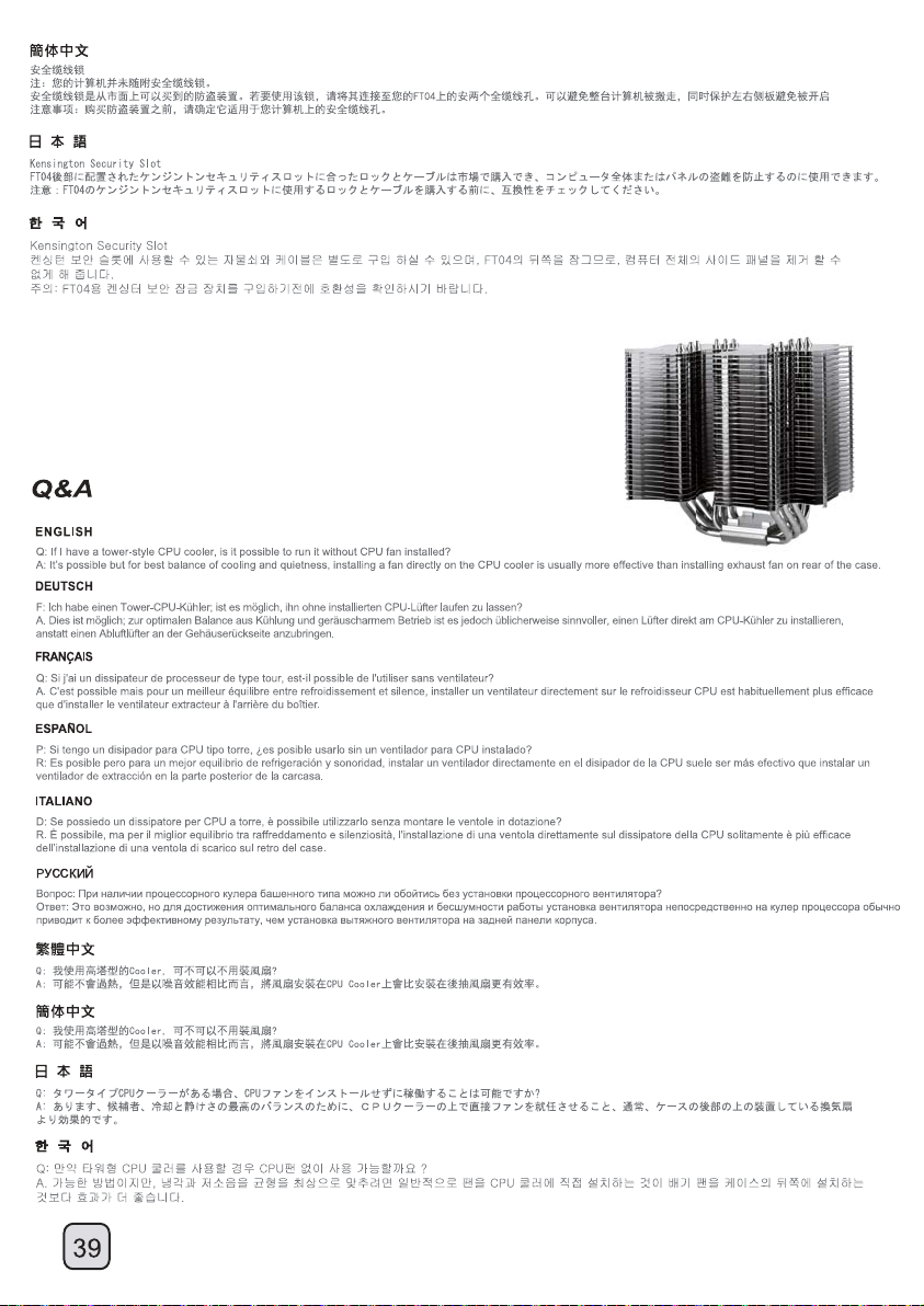
Page 41

Page 42
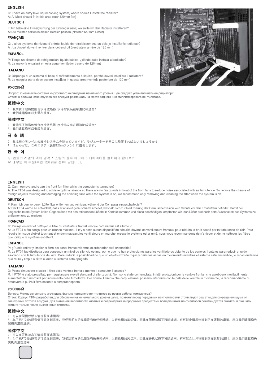
41
Page 43

Page 44

Page 45

Page 46
Warranty Information
This product has a limited 1 year warranty in North America, and Australia.
For information on warranty periods in other regions, please contact your reseller or SilverStone authorized distributor.
Warranty terms & conditions
1. Product component defects or damages resulted from defective production is covered under warranty.
Defects or damages with the following conditions will be fixed or replaced under SilverStone Technology’s jurisdiction.
a) Usage in accordance with instructions provided in this manual, with no misuse, overuse, or other inappropriate actions.
b) Damage not caused by natural disaster (thunder, fire, earthquake, flood, salt, wind, insect, animals, etc…)
c) Product is not disassembled, modified, or fixed. Components not disassembled or replaced.
d) Warranty mark/stickers are not removed or broken.
Loss or damages resulted from conditions other than ones listed above are not covered under warranty.
2. Under warranty, SilverStone Technology’s maximum liability is limited to the current market value for the product (depreciated value, excluding
shipping, handling, and other fees). SilverStone Technology is not responsible for other damages or loss associated with the use of product.
3. Under warranty, SilverStone Technology is obligated to repair or replace its defective products. Under no circumstances will SilverStone
Technology be liable for damages in connection with the sale, purchase, or use including but not limited to loss of data, loss of business, loss of
profits, loss of use of the product or incidental or consequential damage whether or not foreseeable and whether or not based on breach of warranty,
contract or negligence, even if SilverStone Technology has been advised of the possibility of such damages.
4. Warranty covers only the original purchaser through authorized SilverStone distributors and resellers and is not transferable to a second hand
purchaser.
5. You must provide sales receipt or invoice with clear indication of purchase date to determine warranty eligibility.
6. If a problem develops during the warranty period, please contact your retailer/reseller/SilverStone authorized distributors or SilverStone
http://www.silverstonetek.com.
Please note that: (i) You must provide proof of original purchase of the product by a dated itemized receipt; (ii) You shall bear the cost of shipping
(or otherwise transporting) the product to SilverStone authorized distributors. SilverStone authorized distributors will bear the cost of shipping
(or otherwise transporting) the product back to you after completing the warranty service; (iii) Before you send the product, you must be issued a
Return Merchandise Authorization (“RMA”) number from SilverStone. Updated warranty information will be posted on SilverStone’s official website.
Please visit http://www.silverstonetek.com for the latest updates.
Additional info & contacts
For North America (usasupport@silverstonetek.com)
SilverStone T echnology in North America may repair or replace defective product with refurbished product that is not new but has been functionally tested.
Replacement product will be warranted for remainder of the warranty period or thirty days, whichever is longer. All products should be sent
back to the place of purchase if it is within 30 days of purchase, after 30 days, customers need to initiate RMA procedure with SilverStone Technology
in USA by first downloading the “USA RMA form for end-users” form from the below link and follow its instructions.
http://silverstonetek.com/contactus.php
For Australia only (support@silverstonetek.com)
Our goods come with guarantees that cannot be excluded under the Australian Consumer Law.
You are entitled to a replacement or refund for a major failure and for compensation for any other reasonably foreseeable loss or damage.
You are also entitled to have the goods repaired or replaced if the goods fail to be of acceptable quality and the failure does not amount to a major failure.
Please refer to above “Warranty terms & conditions” for further warranty details.
SilverStone Technology Co., Ltd. 12F No. 168 Jiankang Rd., Zhonghe Dist., New Taipei City 235 Taiwan R.O.C. + 886-2-8228-1238
(standard international call charges apply)
For Europe (support.eu@silverstonetek.de)
For all other regions (support@silverstonetek.com)
Page 47
Page 48

Issue date: January, 2013
G11218050
 Loading...