

Page 1
DS380
Premium SFF chassis
with unbelievable storage capacity
Page 2
DATA STORAGE SERIES
n from TJ08-E
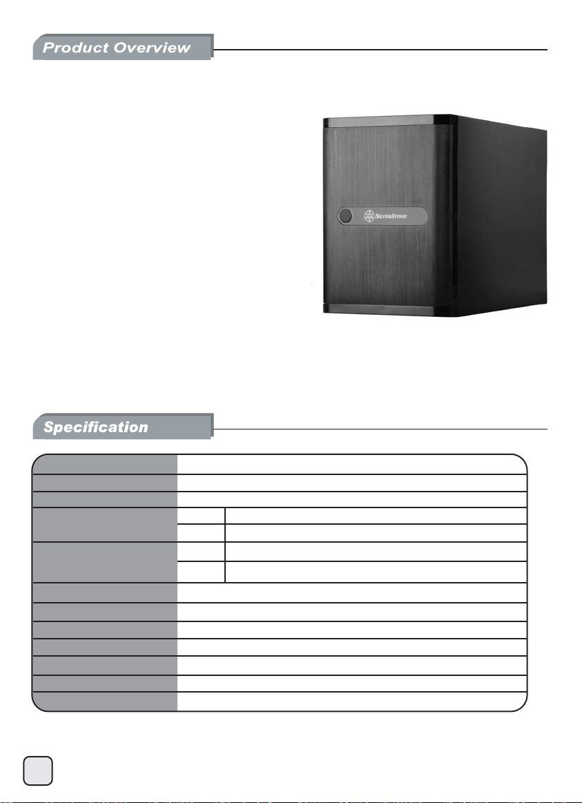
DS380
Premium SFF chassis
with unbelievable storage capacity
Unbelievable storage space and versatility for small
•
form factor
Support 12 total drives with 8 hot-swappable 3.5” or 2.5”
•
SAS/SATA and 4 fixed 2.5” drives
•
Premium brushed aluminum front door
•
Support graphics card up to 11” with supporter design from TJ08-E
Lockable power button design and adjustable LED from GD07
•
Includes three 120mm fans with filtered intake vents
•
Model No.
Material
Motherboard
Drive Bay
Cooling System
Expansion Slot
Front I/O Port
Power Supply
Expansion Card
Limitation of CPU cooler
Dimension
Extra
1
SST-DS380B
Aluminum front door, SECC body
Mini-DTX, Mini-ITX
External
Internal
Rear
Left
USB 3.0 x 2、audio x 1、MIC x 1
SFX PSU (sold separately)
*Compatible with 11” long and 4.38” wide
57mm
211mm (W) x 285mm (H) x 360mm (D), 21.6 liters
Kensington lock
*Installation of expansion card up to maximum size will occupy one hot-swap bay space,
please refer user manual for more information.
3.5” SAS/ SATA hot-swap x 8 (2.5” compatible)
2.5” x 4
1 x 120mm 1200rpm 22dBA
2 x 120mm 1200rpm 22dBA
2
Page 3
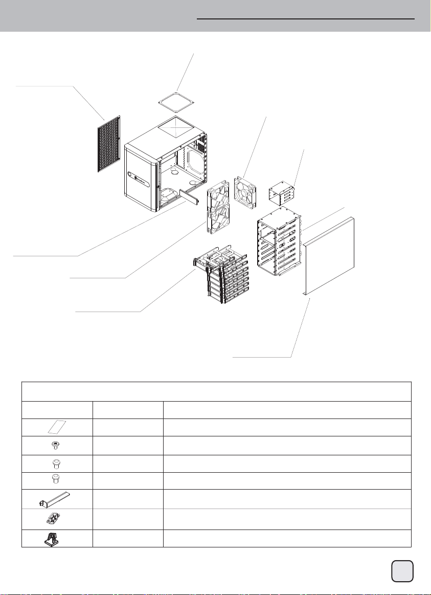
Disassemble chart
SIDE FILTER
DRIVE COVER
12025 FAN*2
DRIVE TRAY*8
TOP FILTER
12025FAN
2.5" DRIVE BRACKET
3.5" DRIVE CAGE
SIDE COVER
SPARE-PARTS
PICTURE ITEM PURPOSE
MANUAL
SCREW-A(632*5)
SCREW-B(M3*4)
SCREW-C(M3*6)
VGA-SUPPORT-BR
ACKET
KEY
CABLE TIE
USER INSTALLATION GUIDE
PSU*3, MOTHERBOARD*4, 3.5’HDD*32 AND DRIVE CAGE*8
REAR DRIVE CAGE (2.5” HDD/SSD*16)
FRONT DRIVE CAGE (2.5” HDD/SSD*32)
A HOLDER MODULE FOR LONG VGA/EXPANSION CARD
FOR THE FRONT DOOR LOCK
CABLE MANAGEMENT
2
Page 4
Front I/O connector guide
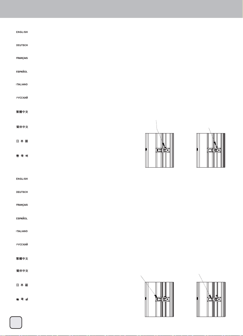
(1) Adjust LED indicator brightness
DS380’s front door contains a slider to adjust LED brightness. If you need to adjust brightness,
we suggest turning on the system first with the door closed and then open the front door
to adjust the brightness slider up and down to desired level.
An der Fronttür des DS380 finden Sie einen Schieber zum Einstellen der LED-Helligkeit. Wenn Sie die Helligkeit
verändern möchten, sollten Sie das System zunächst mit geschlossener Fronttür einschalten, anschließend die
Tür öffnen und die gewünschte Helligkeit mit dem Schieber einstellen.
Le panneau frontal du DS380 contient un curseur pour paramétrer la luminosité du DEL. Si vous souhaitez
paramétrer la luminosité, nous vous suggérons de mettre le système en marche d'abord avec le panneau
fermé puis d'ouvrir le panneau pour paramétrer le curseur de luminosité vers le haut ou vers le bas vers le niveau désiré.
La puerta frontal de la DS380 contiene un control deslizante para ajustar el brillo del LED.
Si necesita ajustar el brillo, le sugerimos que primero encienda el sistema con la puerta cerrada y
luego abra la puerta frontal para ajustar el deslizante del brillo arriba y abajo hasta el nivel deseado.
Lo sportello frontale di DS380 è dotato di un dispositivo di scorrimento per regolare la luminosità del LED.
Se è necessario regolare la luminosità, prima accendere il sistema con lo sportello chiuso e quindi aprire lo
sportello frontale per regolare il dispositivo di scorrimento della luminosità verso l’alto o il basso fino al livello voluto.
На передней дверце DS380 расположен регулятор яркости светодиодов. Для регулировки яркости
рекомендуется сначала включить систему с закрытой передней дверцей, а затем открыть дверцу
и установить требуемый уровень яркости при помощи регулятора.
DS380前門板內有LED亮度調整遮光罩。如您需要進行亮度調整,我們建議您開機後,
先上下調整門板內遮光罩的位置,再將門板關上看看亮度是否滿意,
如不滿意可再打開門板進行調整。
DS380前门板内有LED亮度调整遮光罩。如您需要进行亮度调整,我们建议您开机后,
先上下调整门板内遮光罩的位置,再将门板关上看看亮度是否满意,
如不满意可再打开门板进行调整。
DS380のフロントドアには、LED輝度を調節するスライダーが装備されています。輝度の調節が必要な場合は、
ドアを閉めた状態でシステムを起動させ、それからフロントドアを開けて輝度のスライダーで
必要なレベルに調節するようお勧めします。
DS380의 전면 도어 안에 LED 밝기를 조정하는 슬라이더가 있습니다. 밝기를 조정해야 할 경우
먼저 도어가 닫힌 상태에서 시스템을 켠 후 전면 도어를 열고 밝기 슬라이더를 위아래로 밀어
원하는 레벨로 조정합니다.
(2) Power button lock
LED brightness adjustment (dim)
LED brightness adjustment (bright)
The front door contains a power button lock. When the power button lock is locked, you will disable the power button on the front door, the only way to press the power button is by
opening the front door again. After closing the front door, you can use the key to lock front door and disable the power button completely. This unique design is to prevent the power
button from being pressed accidentally.
An der Fronttür gibt es eine Möglichkeit zum Sperren der Netztaste. Wenn die Netztastensperre aktiv ist, wird die Netztaste an der Fronttür außer Kraft gesetzt. Die Netztaste kann nun
nur noch betätigt werden, wenn die Fronttür erneut geöffnet wird. Nach dem Schließen der Fronttür können Sie die Tür mit dem Schlüssel verriegeln und die Netztaste so komplett außer
Kraft setzen. Auf diese Weise können Sie verhindern, dass die Netztaste aus Versehen betätigt wird.
Le panneau frontal contient un verrou du bouton d'alimentation. Quand le bouton d'alimentation est verrouillé, vous devez désactiver le bouton d'alimentation du panneau frontal, le seul
moyen est d'appuyer sur le panneau frontal à nouveau. Après la fermeture du panneau frontal, vous pouvez utiliser la clé pour verrouiller le panneau frontal et désactiver complètement le
bouton d'alimentation. Ce design unique sert à éviter les appuis accidentels sur le bouton d'alimentation.
La puerta frontal contiene un cierre del botón de potencia. Cuando el botón de potencia esté bloqueado, se desconectará el botón de potencia de la puerta frontal, el único modo de
presionar el botón de potencia es abrir de nuevo la puerta frontal. Tras cerrar la puerta frontal podrá usar la llave para bloquear la puerta frontal y desconectar el botón de potencia
totalmente. Este diseño único es para evitar que el botón de potencia se presione de forma accidental.
Lo sportello frontale è dotato di un di blocco del tasto d’alimentazione. Quando il blocco tasto del tasto d’alimentazione è attivato, il tasto d’alimentazione dello sportello frontale è disabilitato,
e l'unico modo per premere il tasto d’alimentazione è quello di aprire di nuovo lo sportello frontale. Dopo aver chiuso lo sportello frontale, si può usare la chiave per bloccare lo sportello frontale
e disabilitare del tutto il tasto d’alimentazione. Questo sistema unico, è progettato per impedire la pressione accidentale del tasto d’alimentazione.
На передней дверце расположен блокиратор кнопки питания. Когда кнопка питания заблокирована, кнопка питания на передней дверце не действует. Чтобы нажать кнопку питания
потребуется снова открыть переднюю дверцу. После закрытия передней дверцы ее можно заблокировать при помощи ключа и полностью деактивировать кнопку питания. Эта
уникальная конструкция позволяет избежать случайного нажатия кнопки питания
DS380前門板內有電源開關鎖。扣上時可讓門板上的電源開關失效,只有打開門板才能按下開關。關上前門板後,只要使用鑰匙鎖住門板,電源開關就完全無法使用。這個設計可以避免小孩子
不小心誤觸電源開關。
DS380前门板内有电源开关锁。扣上时可让门板上的电源开关失效,只有打开门板才能按下
开关。关上前门板后,只要使用钥匙锁住门板,电源开关就完全无法使用。这个设计可以
避免小孩子不小心误触电源开关。
DS380のフロントドアには、LED輝度を調節するスライダーが装備されています。輝度の調節が
必要な場合は、ドアを閉めた状態でシステムを起動させ、それからフロントドアを開けて輝度の
スライダーで必要なレベルに調節するようお勧めします。
전면 도어 안에 전원 버튼 잠금장치가 있습니다. 전원 버튼 잠금장치가 잠가진 경우
전면 도어의 전원 버튼을 사용할 수 없으며, 전원 버튼을 누를 수 있는 유일한 방법은
전면 도어를 다시 열어야 합니다. 전면 도어를 닫은 후, 키를 사용하여 전면 도어를
잠가 전원 버튼을 완전히 비활성화할 수 있습니다. 이 독특한 설계로 전원 버튼이
우발적으로 눌려지는 것을 방지할 수 있습니다.
.
Open Locked
3
Page 5
Installation guide
To save on time and hassle, before you begin, please make sure that you :
(1) have all components collected.
(2) check that all components do not have compatibility problems with each other or with the case.
(3) if possible, assemble the components outside the case first to make sure they are working.
(4) keep the motherboard manual ready for reference during installation.
(5) prepare a Philips screwdriver.
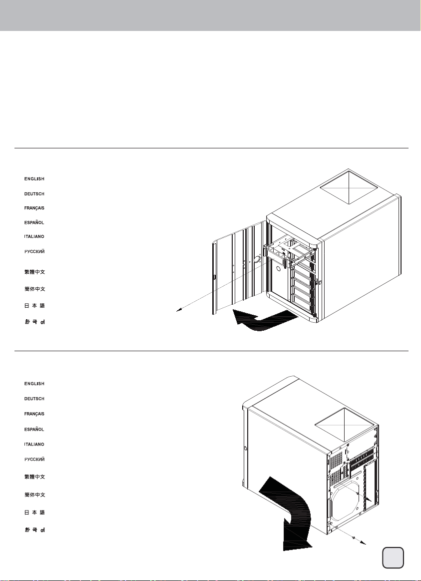
(1)
Open front door and remove all hot-swap trays
Fronttür öffnen und sämtliche Hot-Swap-Halterungen herausnehmen
Ouvrez le panneau frontal et retirez toutes les baies hot-swap
Abra la puerta frontal y retire todas las bandejas de cambio en caliente
Aprire lo sportello frontale e rimuovere tutti i cassetti hot-swap
Откройте переднюю дверцу и извлеките все отсеки жестких дисков
с возможностью «горячей» замены.
打開前門,取出所有熱插拔硬碟抽取盤。
打开前门,取出所有热插拔硬盘抽取盘。
フロントドアを開き全てのホットスワップトレイを取り外します。
전면 도어를 열고 모든 핫스왑 트레이를 분리합니다.
(2)
Remove side panel screws to remove side panel
Seitenpanelschrauben herausdrehen und Seitenpanel abnehmen
Retirez les vis du panneau latéral pour le retirer
Quite los tornillos del panel lateral para retirar el panel lateral
Rimuovere le viti del pannello laterale per rimuovere il pannello laterale
Удалите винты боковой панели, чтобы снять ее.
卸下側板螺絲,將側板取下。
卸下侧板螺丝,将侧板取下。
側面パネルのネジを外して、側面パネルを取り外します。
측면 패널 나사를 풀어 측면 패널을 분리합니다.
4
Page 6
Front I/O connector guide
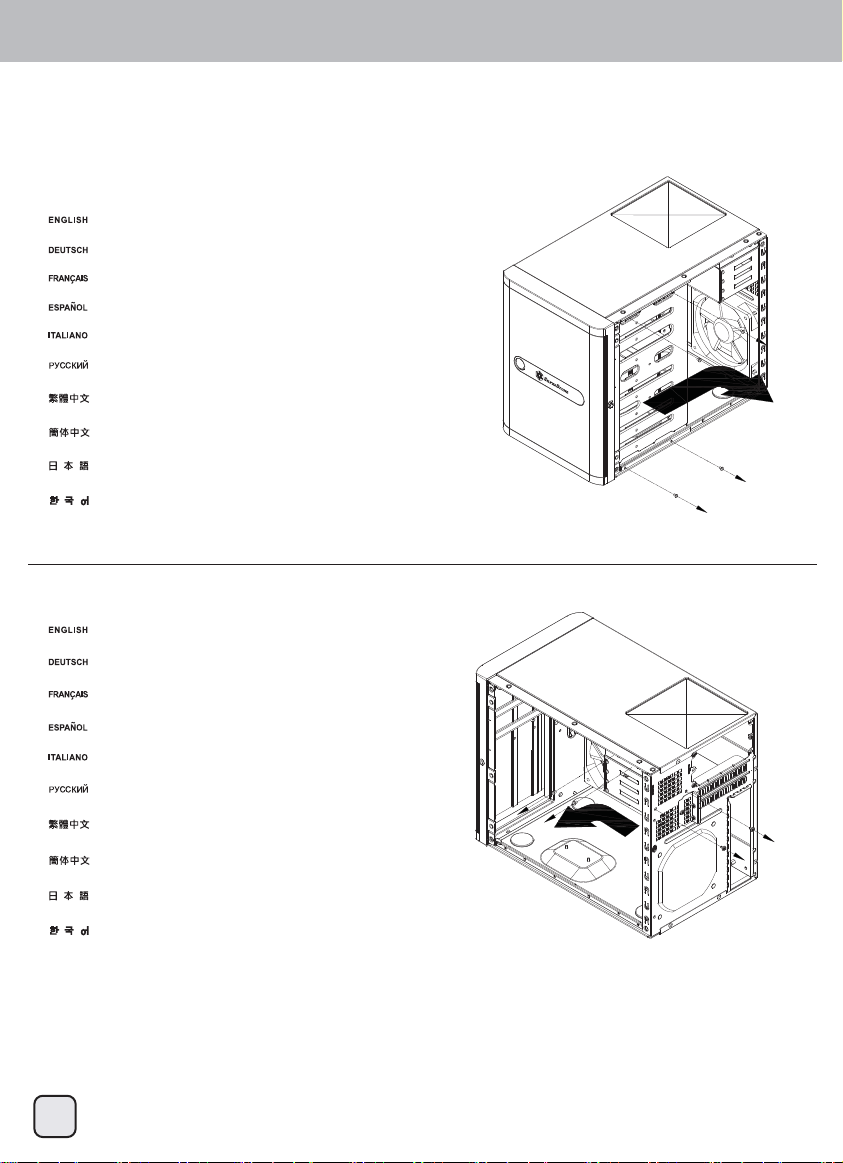
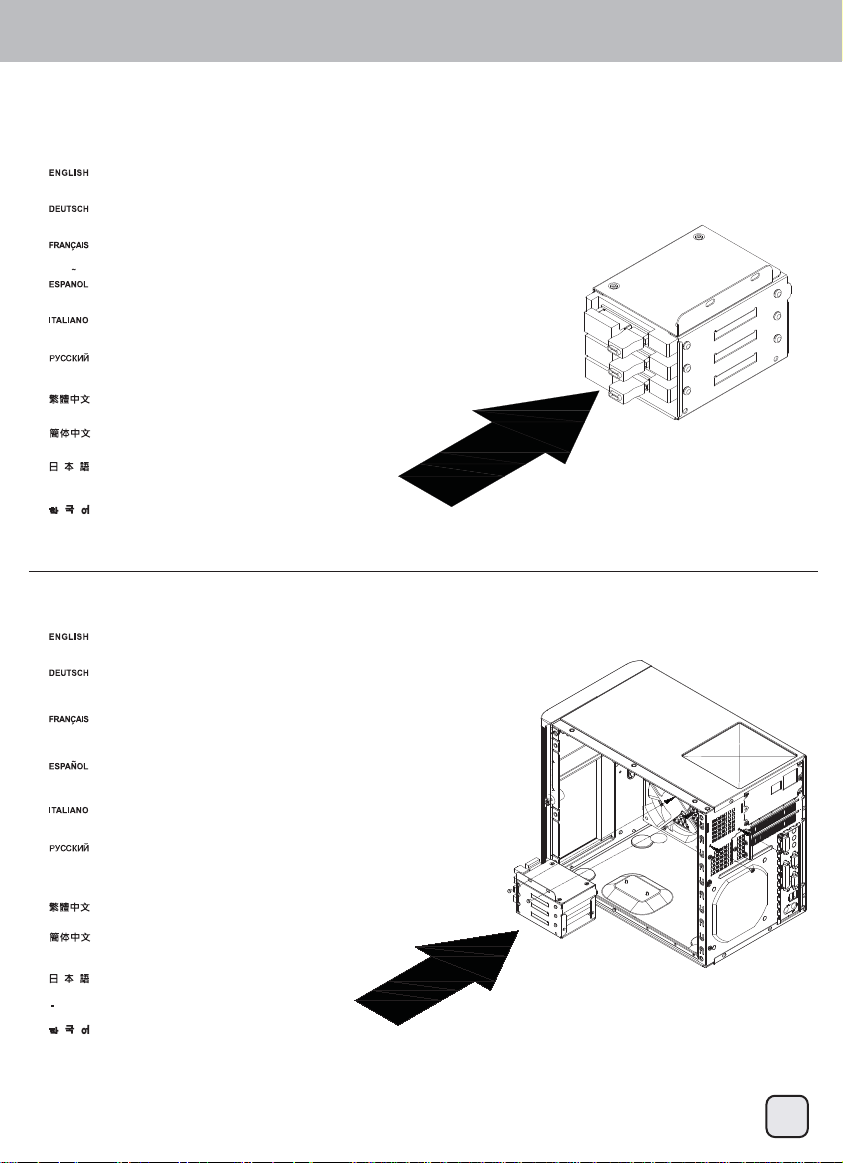
(3)
Remove screws from the primary drive cage to remove it from the case
Schrauben am primären Laufwerkhalter herausdrehen und Halter aus dem Gehäuse nehmen
Retirez les vis de la cage du lecteur primaire pour le retirer du boîtier
Quite los tornillos de la carcasa primaria para dispositivos para retirarla de la carcasa
Rimuovere le viti dalla gabbia unità principale per rimuoverla dal case
Удалите винты с основного кронштейна для жестких дисков, чтобы извлечь его из корпуса.
卸下主硬碟架螺絲,將硬碟架取下。
卸下主硬盘架螺丝,将硬盘架取下。
プライマリドライブケージのネジを外して、ケージをケースから取り外します。
기본 드라이브 케이지에서 나사를 풀어 이를 케이스에서 분리합니다.
(4)
Remove 2.5” drive cage screws to remove it from the case
Schrauben am 2,5-Zoll-Laufwerkhalter herausdrehen und Halter aus dem Gehäuse nehmen
Retirez les vis de 2,5" de la cage du lecteur primaire pour le retirer du boîtier
Quite los tornillos de la carcasa para dispositivos de 2,5” para retirarla de la carcasa
Rimuovere le viti dalla gabbia unità 2,5” per rimuoverla dal case
Удалите винты с кронштейна для 2,5-дюймовых жестких дисков, чтобы извлечь его из корпуса.
卸下2.5吋硬碟架螺絲,取下2.5吋硬碟架。
卸下2.5吋硬盘架螺丝,取下2.5吋硬盘架。
2.5”ドライブケージのネジを外して、ケージをケースから取り外します。
2.5” 드라이브 케이지 나사를 풀어 이를 케이스에서 분리합니다.
5
Page 7
Installation guide
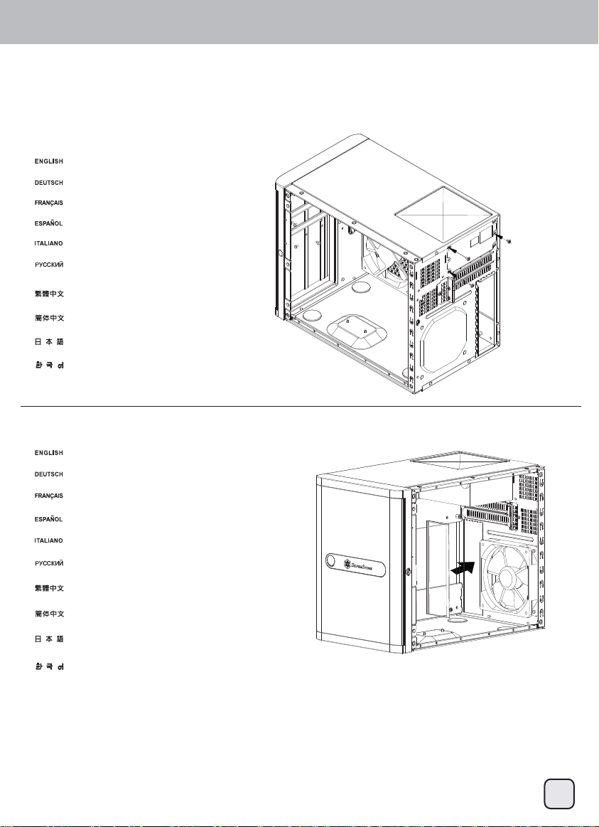
(5)
Install SFX power supply
SFX-Netzteil installieren
installez la source d'alimentation SFX
Instale la fuente de alimentación SFX
Installazione della PSU SFX
Установите блок питания SFX.
安裝SFX規格電源供應器。
安装SFX规格电源供应器。
SFX電源を取り付けます。
SFX 전원 공급장치를 설치합니다.
(6)
Install motherboard I/O shield plate to the case
Motherboard-I/O-Blech am Gehäuse installieren
Installez la plaque de protection I/O de la carte mère sur le boîtier
Instale la placa de E/S de la placa base a la carcasa
Installare la piastra di protezione I/O scheda madre sul case
Установите в корпус панель портов ввода-вывода системной платы.
安裝主機板的I/O檔片。
安装主机板的I/O档片。
マザーボードI/Oシールドプレートをケースに取り付けます。
메인보드 I/O 쉴드 플레이트를 케이스에 설치합니다.
6
Page 8
Front I/O connector guide
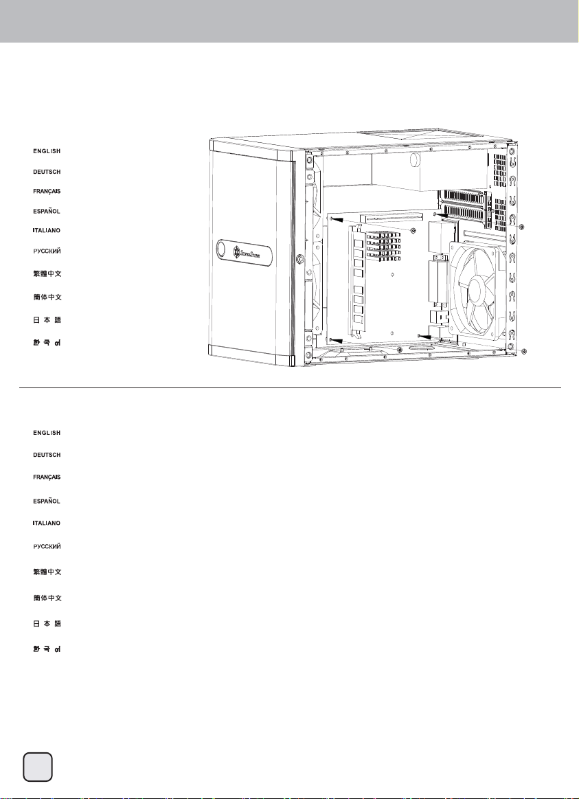
(7)
Install motherboard
Motherboard installieren
Installez la carte mère
Instale la placa base
Installare la scheda madre
Установите системную плату.
安裝主機板。
安装主机板。
マザーボードを取り付けます。
메인보드를 설치합니다.
(8)
We recommend connecting all cables required on the motherboard now
Wir empfehlen, jetzt sämtliche benötigten Kabel an das Motherboard anzuschließen.
Nous vous recommandons de connecter maintenant tous les câbles nécessaires sur la carte mère
Le recomendamos conectar todos los cables necesarios para la placa base ahora
Si consiglia di collegare tutti i cavi necessari alla scheda madre a questo punto dell’installazione
На этом этапе рекомендуется подключить к системной плате все необходимые кабели.
我們建議您在這時接上主機板所需要之線材。
我们建议您在这时接上主机板所需要之线材。
この時点でマザーボードに必要なケーブルを全部接続するようお勧めします。
이 시점에서 메인보드에 필요한 모든 케이블을 연결할 것을 권장합니다.
7
Page 9
Installation guide
(9)
Install 2.5” drives into the 2.5” drive cage, if there are insufficient SATA connectors,
we recommend using SilverStone’s CP06-E.
Installieren Sie die 2,5-Zoll-Laufwerke im 2,5-Zoll-Laufwerkhalter. Falls nicht genügend
SATA-Anschlüsse vorhanden sind, empfehlen wir SilverStones CP06-E.
Installez les lecteurs de 2,5” sur la cage du boîtier de 2,5”, s'il n'y a pas assez de connecteurs SATA,
nous vous recommandons d'utiliser SilverStone’s CP06-E.
Instale los dispositivos de 2,5” en la carcasa para dispositivos de 2,5”, si no tiene conectores SATA
suficientes, le recomendamos usar el SilverStone CP06-E
Installare unità 2,5" nella gabbia unità 2,5"; se non ci sono connettori SATA sufficienti, si consiglia
di utilizzare CP06-E SilverStone.
Установите 2,5-дюймовые жесткие диски в кронштейн для 2,5-дюймовых жестких дисков. Если
недостаточно разъемов SATA, рекомендуется использовать кабель SilverStone CP06-E.
將2.5吋硬碟安裝在2.5吋硬碟架上。如果SATA線材接頭不夠,我們建議您使用CP06-E進行擴充。
将2.5吋硬盘安装在2.5吋硬盘架上。如果SATA线材接头不够,我们建议您使用CP06-E进行扩充。
2.5”ドライブを2.5”ドライブケージに装着しますが、SATAコネクタが足りない場合
はSilverStone製CP06-Eの使用をお勧めします。
2.5” 드라이브를 2.5” 드라이브 케이지를 설치합니다. SATA 커넥터가 충분치 않을
경우 SilverStone의 CP06-E를 사용할 것을 권장합니다.
(10)
If you are using a modular power supply, connect all required cables to it first before reinstalling the 2.5” drive cage back
into the case. All cables required for the drives installed in the 2.5” drive cage should all be connected as well.
Wenn Sie ein modulares Netzteil verwenden, schließen Sie alle nötigen Kabel zuerst daran an, bevor Sie den
2,5-Zoll-Laufwerkhalter wieder im Gehäuse installieren. Nun sollten Sie auch sämtliche Kabel an die Laufwerke
im 2,5-Zoll-Laufwerkhalter anschließen.
Si vous utilisez une source d'alimentation modulaire, connectez-y d'abord tous les câbles nécessaires avant de
réinstaller la cage de lecteurs de 2,5" dans le boîtier. Tous la câbles nécessaires aux lecteurs installés dans la
cage de lecteurs 2,5" doivent aussi être connectés.
Si está usando una fuente de alimentación modular, conéctele todos los cables necesarios primero antes de
reinstalar la carcasa para dispositivos de 2,5” en la carcasa. Todos los cables necesarios para los dispositivos
instalados en la carcasa para dispositivos de 2,5” también deberían conectarse.
Se si utilizza un alimentatore modulare, collegare tutti i cavi necessari prima di reinstallare la gabbia 2,5" nel case.
Anche tutti i cavi necessari per le unità installate nella gabbia unità 2,5" devono essere collegati.
Если используется модульный блок питания, сначала подключите к нему все требуемые кабели,
и только после этого устанавливайте кронштейн для 2,5-дюймовых жестких дисков обратно в корпус.
Также должны быть подключены все кабели к жестким дискам, установленным в кронштейн для
2,5-дюймовых жестких дисков.
確認電源供應器模組化線材都已安裝完畢後,裝回2.5吋硬碟架。此時2.5吋硬碟的線材都應該全部安裝完畢。
确认电源供应器模块化线材都已安装完毕后,装回2.5吋硬盘架。此时2.5吋硬盘的
线材都应该全部安装完毕。
モジュラー電源を使用される場合、2.5”ドライブケージをケースに戻す前に、
全ての必要なケーブルを接続してください。2.5”ドライブケージに装着さ
れるドライブに必要なケーブルも同様に接続します。
모듈식 전원 공급장치를 사용하는 경우 2.5” 드라이브 케이지를 케이스에 도로 설치하기 전에 필요한 모든
케이블을 전원 공급장치에 연결합니다. 2.5” 드라이브 케이지에 설치된 드라이브에 필요한 모든 케이블도
마찬가지로 연결해야 합니다.
8
Page 10
Front I/O connector guide
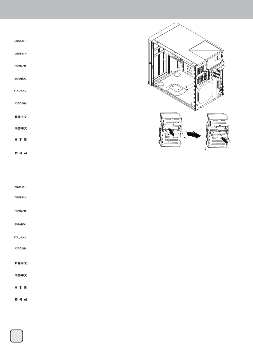
(11)
Install expansion card. If necessary you can convert the third drive slot in the primary drive cage into a
holder module for long expansion cards.
Installieren Sie Erweiterungskarten. Falls nötig, können Sie den dritten Laufwerkschacht im primären
Laufwerkhalter in einen Halter für lange Erweiterungskarten umwandeln.
Installez la carte d'extension. Si nécessaire, vous pouvez convertir la troisième fente de lecteur de la cage
du lecteur primaire en un module de support pour les longues cartes d'extension.
Instale la tarjeta de expansión. Si es necesario puede convertir el tercer zócalo de la carcasa primaria para
dispositivos en un módulo de soporte para tarjetas de expansión largas.
Installare scheda di espansione. Se necessario, è possibile convertire il terzo alloggio unità della gabbia principale in
un modulo di supporto per le schede di espansione lunghe.
Установите плату расширения. При необходимости можно переоборудовать в опорный модуль для длинных
плат расширения третий отсек для жесткого диска в основном кронштейне для жестких дисков.
安裝介面卡,如果您的介面卡比較大張,建議您可以將主硬碟架第3槽位更換為長卡模組。
安装适配卡,如果您的适配卡比较大张,建议您可以将主硬盘架第3槽位更换为长卡模块。
拡張カードを装着します。必要であればプライマリドライブケージの第3ドライブスロットを長尺拡張カードのホルダーモジ
ュールとして利用できます。
확장 카드를 설치합니다. 필요한 경우 기본 드라이브 케이지에 있는 세 번째 슬롯을 긴 확장 카드용 홀더
모듈로 전환할 수 있습니다.
(12)
Place the primary drive cage on the case and connect all SATA/SAS cables, 4pin peripheral cables from the power supply, and the fan cables to the drive cage backplane.
Stellen Sie den primären Laufwerkhalter auf das Gehäuse, schließen Sie sämtliche SATA/SAS-Kabel, die vierpoligen Peripherie-Stromkabel vom Netzteil und die Lüfterkabel
an die Rückwand des Laufwerkhalters an.
Regular module Module with long
expansion card holder
Placez la cage du lecteur primaire sur le boîtier et connectez tous les câbles SATA/SAS, les câbles périphériques à 4 broches à partir de la source d'alimentation, puis les
câbles de ventilateurs sur le fond de panier de la cage du lecteur.
Coloque la carcasa primaria para dispositivos en la carcasa y conecte todos los cables SATA/SAS, cables de 4 pines para periféricos desde la fuente de alimentación y
cables para ventiladores a la parte posterior de la carcasa para dispositivos.
Si consiglia di collegare tutti i cavi necessari alla scheda madre a questo punto dell’installazione
Поместите основной кронштейн для жестких дисков на корпус и подключите к коммутационной панели кронштейна для жестких дисков все кабели SATA/SAS,
-контактные кабели для периферийных устройств от блока питания и кабели от вентиляторов.
將主硬碟架先放在機殼上,開始連接硬碟背板線材,包含排線、大4pin電源輸入及側邊系統風扇線材,請全部連接於硬碟背板。
将主硬盘架先放在机壳上,开始连接硬盘背板线材,包含排线、大4pin电源输入及侧边系统风扇线材,请全部连接于硬盘背板。
この時点でマザーボードに必要なケーブルを全部接続するようお勧めします。
기본 드라이브 케이지를 케이스에 올려 놓고 모든 SATA/SAS 케이블, 전원 공급장치의 4핀 주변장치 케이블, 팬 케이블을 드라이브 케이지의 뒷면에 연결합니다.
9
Page 11

Installation guide
(13)
With all cables connected, carefully reinstall the primary drive cage back into the case.
Bauen Sie den primären Laufwerkhalter mit sämtlichen angeschlossenen Kabeln sorgfältig wieder in das Gehäuse ein.
Une fois tous les câbles connectés, réinstallez avec soin la cage du lecteur primaire dans le boîtier.
Con todos los cables conectados, reinstale de nuevo la carcasa primaria para dispositivos en la carcasa.
Con tutti i cavi collegati, reinstallare accuratamente la gabbia principale nel telaio.
Подключив все кабели осторожно установите основной кронштейн для жестких диско обратно в корпус.
由於已連接線材,請小心地將主硬碟架裝回機殼。
由于已连接线材,请小心地将主硬盘架装回机壳。
全てのケーブルが接続されたら、プライマリドライブケージをケースにきちんと戻します。
모든 케이블이 연결된 상태에서 기본 드라이브 케이지를 주의해서 도로 케이스에 설치합니다.
(14)
Reinstall side panel
Seitenpanel wieder anbringe
Réinstallez le panneau latéral
Reinstale el panel lateral.
Reinstallare il pannello laterale
Установите на место боковую панель.
將側板裝回機殼
将侧板装回机壳。
側面パネルを戻します。
측면 패널을 다시 설치합니다.
10
Page 12

Front I/O connector guide
(15)
Install drives into the hot-swap trays.
Installieren Sie Laufwerke in den Hot Swap-Einschüben.
Installez les lecteurs dans les baies hot-swap.
Instale los dispositivos en las bandejas para cambio en caliente.
Installare le unità nei cassetti hot-swap.
Установите жесткие диски в отсеки с возможностью «горячей» замены.
將熱插拔硬碟安裝至硬碟抽取盤。
将热插拔硬盘安装至硬盘抽取盘。
ドライブをホットスワップトレイに装着します。
드라이브를 핫스왑 트레이 안에 설치합니다.
(16)
Reinsert the trays with hard drives installed back into the case to complete installation.
Setzen Sie die Einschübe mit den installierten Laufwerken zum Abschluss der Installation wieder in das Gehäuse ein.
Réinsérez les baies avec les disques durs réinstallés dans le boîtier pour terminer l'installation.
Reinserte las bandejas con los discos duros instalados de nuevo en la carcasa para completar la instalación.
Reinserire i vassoi con i dischi rigidi installati nel case per completare l'installazione.
Для завершения установки вставьте отсеки с жесткими дисками обратно в корпус.
插回所有的硬碟抽取盤,完成安裝。
插回所有的硬盘抽取盘,完成安装。
ハードディスクドライブを装着したトレイをケースに戻すと、インストール完了です。
하드 드라이브가 설치된 트레이를 도로 케이스에 삽입하여 설치를 완료합니다
11
Page 13

Connector definition
(1) Front panel connector installation
Power switch and reset switch installation guide:
Please refer to the motherboard manuals for the motherboard’s “Front Panel Connector” or “System Panel Connector” pin definitio
Power switch and reset switch have no polarity, so they can be connected in any orientation.
Bitte suchen Sie in der Motherboard-Dokumentation nach der Pinbelegung der Anschlüsse des Frontbedienfeldes („Front Panel Conne
oder „ System Panel Connectors“). Ein-/Austaste und Rücksetztaste benötigen keine bestimmte Polarität, können daher beliebig (o
und - zu achten) angeschlossen werden.
Veuillez-vous référer au manuel de votre carte mère pour la description des broches "des connecteurs du panneau frontal" et des broches
"des connecteurs du panneau système". Les interrupteurs d'allumage et de réinitialisation ne possède pas de polarité, donc ils peuvent être
branché dans les deux sens.
Por favor, consulte en los manuales de la placa base la configuración de pines del “Conector de panel frontal” ó “Conector de panel de sistema”
de su placa base. Los interruptores de encendido y reseteo no tienen polaridad, luego se pueden conectar con cualquier orientac
Fare riferimento al manuale della scheda madre nella sezione “Connettori del pannello frontale” o “Connettori del pannello di sistema”. Power
switch e reset switch non hanno polarità, posso essere pertanto connessi con qualsiasi orientamento.
Описание контактов разъемов приведены в разделах “Разъемы передней панели” или “Разъемы системной панели” руководства
пользователя материнской платы. Выключатель питания и кнопка перезагрузки не имеют полярности, поэтому их можно подключать
в любой ориентации.
請參考主機說明書的Front Panel Connectors安裝Pin Define,將Connector插上;Power Switch 與Reset Switch並無正負極性之分,
反插正插都不影響功能性。
请参考主机说明书的Front Panel Connectors安装Pin Define,将Connector插上;Power Switch 与
反插正插都不影响功能性。
マザーボードの「フロントパネルコネクタ」または「システムパネルコネクタ」のピン配列についてはマザーボードマニュアルを参照してください。
電源スイッチとリセットスイッチに極性はないので、いずれの方向でも接続できま。
메인보드 매뉴얼의 전면패널 커넥터 혹은 시스템패널 커넥터 핀을 참조하기 바랍니다. 파워 스위치와 리셋 스위치는 극성이 없어 어떤
방향으로 설치해도 무방합니다.
Reset Switch并无正负极性之分,
12
Page 14

Connector definition
LED connector installation guide:
Please refer to the motherboard manuals for the motherboard’s “Front Panel Connector ” or “System Panel Connector” pin definition.; the white/black
wires are negative while other colors are positive wires. The Power LED wires are separate pins for compatibility with different motherboard pin
definition so please make sure they are connected in the right polarity by referring to your motherboard manual.
Bitte suchen Sie in der Motherboard-Dokumentation nach der Pinbelegung der Anschlüsse des Frontbedienfeldes („Front Panel Connectors“ oder „
System Panel Connectors“). Die weißen/ schwarz Adern sind negativ (-), die farbigen Adern positiv (+).Die Kabel für die Betriebsanzeige-LED sind
zur Kompatibilität mit unterschiedlichsten Motherboards einzeln, nicht als kompletter Stecker ausgeführt. Achten Sie hier bitte auf die richtige
Polarität, lesen Sie in der Dokumentation Ihres Motherboards nach.
Veuillez-vous référer au manuel de votre carte mère pour la description des broches "des connecteurs du panneau frontal" et des broches "des connecteurs du panneau
système". Les câbles colorés en blanc/noir sont négatifs alors que ceux d'une autre couleur sont positifs. Les câbles de la LED Power sont séparés afin d'être compatible
avec différentes cartes mères, donc vérifiez bien qu'ils sont branchés avec la bonne polarité en vous référant au manuel de votre carte mère
Por favor, consulte en los manuales de la placa base la configuración de pines del “Conector de panel frontal” ó “Conector de panel de sistema” de
su placa base. Los cables de color blanco/negro son negativos mientras que los de color son positivos. Los cables LED de potencia tienen pines
separados para compatibilidad con diferentes definiciones de pines de la placa base luego por favor, asegúrese de que están conectados en la
polaridad correcta consultando el manual de su placa base.
Fare riferimento al manuale della scheda madre nella sezione “Connettori del pannello frontale” o “Connettori del pannello di sistema”. I cavi di
colore bianco/nero sono il polo negativo, mentre quelli di colore diverso il positivo.
Описание контактов разъемов приведены в разделах “Разъемы передней панели” или “Разъемы системной панели” руководства
пользователя материнской платы. Белые/черный провода - отрицательной полярности, цветные провода - положительной полярности.
Провода светодиодного индикатора питания имеют отдельные контакты для совместимости с различными типами контактов материнских
плат, поэтому обратитесь к руководству пользователя материнской платы и убедитесь, что полярность соблюдена.
請參考主機說明書的Front Panel Connectors安裝Pin Define,將Connector插上; 白/黑色線的部分為負極,彩色線的部分是正極。
Power LED為了適應各主機板的不同, 特別設計為散Pin樣式,請安心使用。
请参考说明书的Front Panel Connectors安装Pin Define,将Connector插上;白/黑色线的部份为负极,彩色线的部份为正极。
Power LED为了适应主机板的不同, 特别设计为散Pin样式,请安心使用。
マザーボードの「フロントパネルコネクタ」または「システムパネルコネクタ」ピン配列についてはマザーボードマニュアルを参照してください。
白/黑色のリード線はマイナスで、色の着いたリード線がプラスです。電源LEDリード線は種々のマザーボードピン定義と互換性を持たせるため分離されたピ
ンとなっているので、ご使用のマザーボードマニュアルを参照して、適切な極性に接続されるようお確かめください。
메인보드 매뉴얼의 전면패널 커넥터 혹은 시스템패널 커넥터 핀을 참조하기 바랍니다. 하얀/검은선의 경우 음극이며, 다른 색의 경우
양극입니다. 파워 LED 선은 분리되어 다양한 메인보드에서 동작할 수 있도록 되어 있습니다. 그러므로 메인보드 매뉴얼을 참조하여 올바를
극성을 주의해 선택하시기 바랍니다.
13
Page 15

Front I/O connector guide
Below are the front I/O connectors pin definition, please also check your motherboard manual to cross reference with motherboard’s
front I/O pin headers. SilverStone’s I/O connectors are in block type to simplify installation.
Nachstehend finden Sie die Pinbelegung der vorderen E/A-Anschlüsse; bitte gleichen Sie zudem das Handbuch Ihres Motherboards mit
den vorderen E/A-Pinzuweisungen ab. SilverStones E/A-Anschlüsse befinden sich zur Vereinfachung der Installation in Blockart.
Au dessous de la description des broches des ports d'E/S, veuillez aussi vérifier sur le manuel de votre carte mère de manière croisée
que les broches sont correctement placées. Les connecteurs d'E/S de SilverStone sont en bloc pour en simplifier leur installation.
A continuación tiene la definición de pines de los conectores frontales de E/S, también debe consultar el manual de su placa base para c
omprobar la referencia de los pines para E/S frontales. Los conectores de E/S de SilverStone son de bloque para simplificar la instalación.
Di seguito lo schema delle connessioni I/O frontali, confrontare lo schema con quanto riportato sul manuale della scheda madre per
effettuare una controllo incrociato. I connettori I/O Silverstone, per semplificare l’installazione, sono del tipo “a blocco”.
Ниже приведено описание контактов передних разъемов ввода/вывода. Обратитесь также к руководству пользователя материнской
платы за описанием передних разъемов ввода/вывода типа "пин-хедер". Разъемы ввода/вывода "SilverStone" - блочного типа, что
облегчает сборку.
下表為Front I/O Connectors的Pin Define,請參閱主機板說明書的各Front I/O Connectors Pin Define一一核對。
RV03的Front I/O Connectors完全採用集合Pin方式以簡化安裝。
下表为Front I/O Connectors的Pin Define,请参阅主机板说明书的各Front I/O Connectors Pin Define一一核对。
RV03的Front I/O Connectors完全采用集合Pin方式以简化安装。
以下はフロントI/Oコネクタピン配列ですが、お持ちのマザーボードのフロントI/Oピンヘッダは、マザーボードマニュアルをご参照ください。
シルバーストーンのI/Oコネクタは、インストールの容易なブロックタイプになっています。
아래는 전면 I/O 커넥터의 핀 설정이며, 메인보드 매뉴얼을 참조해 메인보드의 전면 I/O 핀 헤더와 맞추어 설치합니다.
Silverstone의 I/O 커낵터는 블록 타이브로 구성되어 설치를 간편화 했습니다.
14
Page 16

Guide to hard drive backplane
Insert side case fan connectors into the
backplane’s fan headers.
Insert two 4pin peripheral connectors into the
corresponding plugs on the backplane.
For connecting to dual channel SAS drives, also
connect to SAS plugs on the left side of the backplane.
1. Insert two 4pin peripheral connectors into the corresponding plugs on the backplane.
2. Insert side case fan connectors into the backplane’s fan headers.
3. For connecting to SATA or single channel SAS drives, connect SATA or SAS connectors to the SATA/SAS plugs on the right side of the backplane.
4. For connecting to dual channel SAS drives, also connect to SAS plugs on the left side of the backplane.
1.Verbinden Sie zwei vierpolige Peripherieverbinder mit den passenden Anschlüssen an der Rückwand.
2.Schließen Sie die Verbinder der seitlichen Gehäuselüfter an die Lüfteranschlüsse an der Rückwand an.
3.Zum Anschluss von SATA- oder Single Channel SAS-Laufwerken schließen Sie die SATA- oder SAS-Verbinder an die SATA/SAS-Anschlüsse an
der rechten Seite der Rückwand an.
4.Zum Anschluss von Dual Channel SAS-Laufwerken schließen Sie auch die SAS-Verbinder an der linken Seite der Rückwand an.
1.Insérez deux connecteurs périphériques à 4 broches dans les prises correspondantes sur le fond de panier.
2.Insérez les connecteurs de ventilateurs latéraux dans les headers de ventilateur.
3.Pour se connecter aux chaînes SATA ou aux lecteurs de chaînes simples SAS, connectez les connecteurs SATA ou SAS aux prises SATA/SAS à droite sur le fond
de panier.
4.Pour se connecter aux lecteurs de chaînes double SAS, connectez aussi les prise SAS à gauche sur le fond de panier.
1.Inserte dos conectores para periféricos de 4 pines en las clavijas correspondientes de la placa posterior
2.Inserte los conectores para el ventilador lateral de la carcasa en la cabecera para ventilador de la placa posterior
3.Para conectar a dispositivos SATA ó SAS de canal único, conecte los conectores SATA ó SAS a las clavijas SATA/SAS del lado derecho de
la placa posterior.
4.Para conectar a dispositivos SAS de canal dual, conecte también a las clavijas SAS del lado izquierdo de la placa posterior.
1.Inserire due connettori periferiche a 4 pin nelle corrispondente spine sul backplane.
2.Inserire i connettori ventola laterali del case nei collettori ventola del backplane.
3.Per il collegamento di unità SATA o di unità SAS a canale singolo, collegare i connettori SATA o SAS alle spine SATA/SAS sul lato destro del
backplane.
4.Per il collegamento di unità SAS a due canali, collegare anche le spine SAS sul lato sinistro del backplane.
1.Подсоедините два 4-контактных разъема для периферийных устройств к соответствующим гнездам на коммутационной панели.
2.Подсоедините разъемы боковых вентиляторов корпуса к разъемам вентиляторов на коммутационной панели.
3.Для подключения жестких дисков с интерфейсом SATA или одноканальным интерфейсом SAS подсоедините разъемы SATA или SAS
гнездам SATA/SAS на правой стороне коммутационной панели.
4.Для подключения жестких дисков с двухканальным интерфейсом SAS также подсоедините разъемы к гнездам SAS на левой стороне
коммутационной панели.
1.請將兩個大4Pin電源接頭,插入背板電源輸入端。
2.請將側邊系統風扇線材,與背板風扇接頭連接。
3.Primary HDD (SATA/SAS connector) 主通道,請將SATA/SAS排線接上右邊SATA/SAS接頭(Single channel for SAS)。
4.Secondary HDD (SAS connector) SAS第二通道,請將SAS排線接上左邊SAS接頭(Dual channel)。
1.请将两个大4Pin电源接头,插入背板电源输入端。
2.请将侧边系统风扇线材,与背板风扇接头连接。
3.Primary HDD (SATA/SAS connector) 主通道,请将SATA/SAS排线接上右边SATA/SAS接头(Single channel for SAS)。
4.Secondary HDD (SAS connector) SAS第二通道,请将SAS排线接上左边SAS接头(Dual channel)。
1. 2つの4ピン周辺装置コネクタをバッックプレートの対応する箇所に挿します。
2. 側面ケースファンコネクタをバックプレートのファンヘッダに接続します。
3. For connecting to SATAまたはシングルチャンネルSASドライブへの接続には、SATAまたは SASコネクタをバックプレート右側のSATA/SASコネクタに接続
します。
4. デュアルチャンネルSASドライブの接続には、バックプレート左側のSASコネクタにも接続します。
1.두 개의 4핀 주변장치 커넥터를 뒷면의 해당 플러그에 삽입합니다.
2.측면 케이스 팬 커넥터를 뒷면의 팬 헤더에 삽입합니다.
3.SATA 또는 단일 채널 SAS 드라이브에 연결하는 경우 SATA 또는 SAS 커넥터를 뒷면 우측에 있는 SATA/SAS 플러그에 연결합니다.
4.이중 채널 SAS 드라이브에 연결하는 경우에는 뒷면 좌측에 있는 SAS 플러그에 연결합니다.
For connecting to SATA or single channel SAS drives,
connect SATA or SAS connectors to the SATA/SAS plugs
on the right side of the backplane.
к
15
Page 17

Component Size Limitations
DS380 was designed to accommodate oversize components, but we still recommend referring to the following dimension guidelines
for future upgrades:
(1) CPU cooler limitation
The height limit is 57mm and there is 5.7mm of clearance around the motherboard’s edge.
Das Höhenlimit beträgt 57 mm, an der Kante des Motherboards verbleiben 5.7 mm Freiraum.
La hauteur maximale est de 57mm et il y a une espace de 5.7mm autour du bord de la carte mère.
La altura límite es de 57mm y existe un espacio de 5.7mm alrededor del extremo de la placa base.
Il limite in altezza è di 57mm e ci sono 5.7mm di tolleranza intorno al bordo della scheda madre.
Максимальная высота кулера – 57мм, и зазор вокруг края материнской платы должен составлять 5.7мм.
Cooler限高是57mm,Cooler外緣允許超出主機板邊界5.7mm。
Cooler限高是57mm,Cooler外缘允许超出主机板边界5.7mm。
高さ制限は57mmであり、マザーボード縁からの間隙は5.7mm。
높이는57mm로 제한되며, 외측은 메인보드 경계 5.7mm까지 초과될 수 있습니다.
Maximum 57mm
Maximum 5.7mm
16
Page 18

Component Size Limitations
(2) PSU limitation
DS380 requires SFX PSU with standard 100mm depth.
Das DS380 benötigt SFX-Netzteile mit einer Standardtiefe von 100 mm.
Le DS380 a besoin de SFX PSU d'une profondeur standard de 100 mm.
La DS380 necesita una FA SFX con una profundidad estándar de 100mm.
DS380 richiede una PSU SFX con profondità standard di 100 mm.
Для корпуса DS380 требуется блок питания SFX стандартной длины: 100 мм.
DS380限定使用長度為100mm的標準SFX電源
DS380限定使用长度为100mm的标准SFX电源
DS380には、標準の100mm奥行きのSFX PSUを必要とします。
DS380는 기본 깊이가 100mm인 SFX PSU가 필요합니다.
(3) Graphic card limitation
A. Primary drive cage with eight hot-swap drives installed
If the primary drive cage is completely filled then there is a strict limitation on graphics card length
*There is a 6 inch limitation for standard width graphics card
*If the card width is less than 2.35 inches, then there are no length limitation
A.Primärer Laufwerkhalter mit acht Hot Swap-Laufwerken installiert
Falls der primäre Laufwerkhalter komplett bestückt wird, gilt eine strenge Längenbeschränkung der Grafikkarte.
*Bei Grafikkarten in Standardbreite besteht eine Beschränkung von 15,24 cm.
*Bei einer Kartenbreite bis 6 cm besteht keine Längenbeschränkung.
A.Cage de lecteur primaire avec huit lecteurs hot-swap installés
Si la cage de lecteur primaire est totalement remplie, il y a alors une limite stricte de la longueur de carte graphique
*La limite de largeur de la carte graphique est de 6 pouces
*Si la largeur de la carte est inférieure à 2,35 pouces, il n'y a alors aucune limite de longueur
A. Carcasa primaria para dispositivos con ocho dispositivos para cambio en caliente instalados
Si la carcasa primaria para dispositivos está totalmente llena existe una limitación estricta para la longitud de las tarjetas gráficas
*Existe una limitación de 6 pulgadas para la anchura estándar de las tarjetas gráficas
*Si la anchura de la tarjeta es menos de 2,35 pulgadas, entonces no hay limitaciones de longitud
A.Gabbia unità principale con otto unità hot-swap installate
Se la gabbia unità principale è riempita completamente, c'è una rigida limitazione sulla lunghezza della scheda grafica
*C'è una limitazione di 6 pollici per la larghezza standard della scheda grafica
*Se la larghezza della scheda è inferiore a 2,35 pollici, allora non ci sono limitazioni sulla lunghezza
A.В основной кронштейн для жестких дисков установлены восемь жестких дисков с возможностью «горячей» замены.
Если основной кронштейн для жестких дисков полностью заполнен, длина видеокарты жестко ограничена:
*длина видеокарты стандартной ширины не должна превышать 15 см (6 дюймов);
*если ширина карты менее 6
A.主硬碟架安裝8顆熱插拔硬碟時
如果主硬碟架要裝滿八顆硬碟,則顯示卡長度限制較為嚴格。
*標準寬度的顯示卡長度限制為6吋。
*如果顯示卡寬度小於2.35吋,長度則無限制(Low profile標準是2.73吋)。
см (2,35 дюйма), ее длина не ограничена.
17
Page 19

Component Size Limitations
A.主硬盘架安装8颗热插拔硬盘时
如果主硬盘架要装满八颗硬盘,则显示卡长度限制较为严格。
*标准宽度的显示卡长度限制为6吋。
*如果显示卡宽度小于2.35吋,长度则无限制(Low profile标准是2.73吋)。
A.プライマリドライブケージには8台のホットスワップドライブが装着可能
プライマリドライブケージが全て埋まっている場合、グラフィックスカードには明確な制限が存在します。
*グラフィックスカードの標準の幅として6インチの制限があります。
*カード幅が2.35インチ以内であれば、長さの制限はありません。
A.8개의 핫스왑 드라이브가 설치된 기본 드라이브 케이지
기본 드라이브 케이지가 완전히 채워진 경우 그래픽 카드 길이 제한을 엄격하게 맞춰야 합니다.
*그래픽 카드 기본 폭에 대한 제한은 6 인치입니다.
*카드 폭이 2.35 인치 미만이면 길이 제한이 없습니다.
B. If your card exceeds above limitations, then you will need to replace the stopper plate on the third drive slot with the holder module for long
expansion cards from the accessories box.
*Maximum graphics card length can be extended to 11 inches
*Maximum width limitation is 4.38 inches
*At approximately 6 to 6.4 inches from the rear, there is no room for side mounted PCI-Express cables
*If the card has backplate, its thickness cannot exceed 3.3mm over the PCB
Example: A card such as GeForce GTX 670 shown in the photo cannot be supported.
B.Falls Ihre Karte die obigen Limits überschreitet, müssen Sie die Anschlagplatte am dritten Laufwerkeinschub durch das Haltermodul für lange
Erweiterungskarten ersetzen; das Haltermodul finden Sie in der Zubehörschachtel.
*Die maximale Grafikkartenlänge kann auf 28 cm erweitert werden.
*Die maximale Breite beträgt 11,12 cm.
*Bei einer Länge von etwa 15 bis 16,3 von hinten gibt es keinen Platz für seitlich installierte PCI-Express-Kabel.
*Falls die Karte mit einer Rückenplatte ausgestattet ist, darf diese nicht mehr als 3,3 mm über die Platine hinausragen.
Example: A card such as GeForce GTX 670 shown in the photo cannot be supported.
B.Si votre carte dépasse les limites ci-dessus, vous devez remplacer la plaque d'arrêt sur la fente du troisième lecteur par le module support des
longues cartes d'extension sur la boite d'accessoires.
*La longueur maximale de la carte graphique peut être étendue à 11 pouces.
*La limite maximale de la largeur est de 4,38 pouces
*A environ 6 à 6,4 pouces de l'arrière, il n'y a pas d'espace pour les câbles de montage latéral PCI-Express
*Si la carte a une plaque arrière, son épaisseur ne peut dépasser le PCB de 3,3 mm
Example: A card such as GeForce GTX 670 shown in the photo cannot be supported.
B. Si su tarjeta excede las limitaciones anteriores, entonces necesitará reemplazar la placa divisoria en el zócalo para el tercer dispositivo con el módulo soporte para
tarjetas de expansión largas de la caja de accesorios.
*La longitud máxima para las tarjetas gráficas se puede extender a 11 pulgadas
*La limitación de anchura máxima es 4,38 pulgadas
*A unas 6 – 6,4 pulgadas de la parte trasera, no hay espacio para cables PCI-Express montados de lado
*Si la tarjeta tiene placa posterior, su grosor no puede exceder de 3,3mm sobre la PCB
Example: A card such as GeForce GTX 670 shown in the photo cannot be supported.
B.Se la scheda eccede le limitazioni di cui sopra, allora sarà necessario sostituire la piastra d’arresto sul terzo alloggio unità con il modulo di
supporto per schede di espansione lunghe, che si trova nella scatola degli accessori.
*La lunghezza massima della scheda grafica può essere estesa a 11 pollici
*La larghezza massima è limitata a 4,38 pollici
*A circa 6 – 6,4 pollici (ca. 15 – 16 cm) dalla parte posteriore, non c'è spazio per i cavi della scheda PCI-Express installata
*Se la scheda ha una piastra posteriore, il suo spessore non può superare 3,3 mm oltre la PCB
Example: A card such as GeForce GTX 670 shown in the photo cannot be supported.
B.Если размеры видеокарты превышают вышеуказанные пределы, потребуется заменить заглушку третьего отсека для жесткого диска
на опорный модуль для длинных плат расширения, находящийся в коробке с принадлежностями.
*Максимальная длина видеокарты: 28 см (11 дюймов).
*Максимальная ширина видеокарты: 11 см (4,38 дюйма)
*На расстоянии приблизительно 15–16 см (6–6,4 дюйма) от задней панели нет места для боковых кабелей PCI-Express.
*Если на плате есть коммутационная панель, она не должна выступать более чем на 3,3 мм над печатной платой.
18
Page 20

Component Size Limitations
B.如果您的顯示卡超過上列的條件,則需要將硬碟架第三槽的檔片置換為零件包裡的長卡模組。
*此時顯示卡長度限制為11吋。
*顯示卡寬度限制為4.38吋。
*從後端量測6~6.4吋的位置,不允許有任何側向接頭,例如PCIE電源連接線。
*如顯示卡背面有支撐,所有背板元件空間不得超出電路板3.3mm 。
例如:Geforce GTX670這種顯示卡就無法支援。
如果您的显示卡超过上列的条件,则需要将硬盘架第三槽的文件片置换为零件包里的长卡模块。
*此时显示卡长度限制为11吋。
*显示卡宽度限制为4.38吋。
*从后端量测6~6.4吋的位置,不允许有任何侧向接头,例如PCIE电源连接线。
*如显示卡背面有支撑,所有背板组件空间不得超出电路板3.3mm 。
例如:Geforce GTX670这种显示卡就无法支持。
B.お持ちのカードが上記制限を上回る場合、付属品ボックスからの長尺拡張カード用のホルダーモジュールで第3ドライブスロットのストッパープレートを取
り換える必要があります。
*最大グラフィックスカード長は11インチまで受け入れられます。
*最大幅の限度は4.38インチです。
*後部から6ないし6.4インチの部分までは、側面マウント式PCI-Expressケーブル用の空間はありません。
*カードにバックプレートが付属する場合、厚さはPCBを3.3mm以上超えることはできません。
Example: A card such as GeForce GTX 670 shown in the photo cannot be supported.
B.카드가 위의 제한을 초과할 경우 세 번째 드라이브 슬롯의 스토퍼 플레이트를 액세서리 상자에 있는 긴 확장 카드용 모듈로
교체해야 합니다.
*그래픽 카드 길이는 최대 11인치까지 확장할 수 있습니다.
*최대 제한 폭은 4.38 인치입니다.
*뒤쪽으로부터 약 6 내지 6.4 인치까지 측면에 장착된 PCI-Express 케이블에 대한 공간이 없습니다.
*카드에 뒷판이 있는 경우 두께가 PCB 위로 3.3mm를 초과해서는 안 됩니다.
Example: A card such as GeForce GTX 670 shown in the photo cannot be supported.
19
Keep-out zone
Regular module Module with long
TOP
Maximum 11”
expansion card holder
Maximum 4.38”
Maximum 4.38mm
Page 21

Drive cable recommendation
Cables with 180 degree or straight connectors are recommended to avoid interference with components on the backplane.
Wir empfehlen Kabel mit um 180 ° gedrehten oder geraden Verbindern, damit keine Komponenten an der Rückwand berührt werden.
Les câbles de 180 degrés ou les connecteurs droits sont recommandés pour éviter les interférences avec les composants sur le fond de panier.
Los cables con conectores de 180 grados o rectos se recomiendan para evitar interferencias con los componentes de la placa posterior.
Sono raccomandati cavi con connettori a 180 gradi o diritti per evitare interferenze con i componenti del backplane.
Во избежание пересечения с компонентами на коммутационной панели рекомендуется использовать кабели с разъемами под углом
180° или прямыми разъемами.
由於硬碟背板上有大量電容元件,建議使用180度的接線會比較好安插。
由于硬盘背板上有大量电容组件,建议使用180度的接线会比较好安插。
バックプレート上のコンポーネントとの鑑賞を避けるため、180度またはストレートコネクタが推奨されます。
뒷면에 있는 구성부품과 걸리지 않도록 하기 위해 180도 또는 직선형 커넥터가 있는 케이블 사용을 권장합니다.
20
Page 22

Optimal Thermal Performance Layout
03
TD03
TD
(1) There is severe height restriction for CPU cooler. We recommend using all-in-one liquid cooling systems if high performance cooling is required.
(2) When choosing a graphics card, we recommend models that have fan blowing exhaust air to the rear slot, this will ensure smooth and efficient
airflow within the DS380 for maximum cooling performance.
(1) Es gibt eine strikte Höhenbegrenzung des CPU-Kühlers. Wir empfehlen ein Alles-in-Einem-Wasserkühlungssystem, wenn Hochleistungskühlung
erforderlich ist.
(2) Bei der Auswahl von Grafikkarten empfehlen wir Modelle, die warme Luft über eine Öffnung im hinteren Teil des Steckplatzes in die Außenwelt
ableiten; dies gewährleistet eine ungestörte und wirksame Luftzirkulation innerhalb des DS380 und sorgt für eine optimale Kühlung.
(1) Il existe une restriction stricte de hauteur de CPU. Nous recommandons d'utiliser les systèmes de refroidissement liquides tout-en-un si une
haute performance de refroidissement est nécessaire.
(2) Quand vous choisissez une carte graphique, nous vous recommandons les modèles qui disposent de ventilateur de sortie sur la fente arrière,
ceci garantissant une ventilation fluide et efficace à l'intérieur du DS380 pour une performance de refroidissement maximale.
(1) Existe una severa restricción de altura para el disipador de la CPU. Le recomendamos usar sistemas de refrigeración líquida todo en uno si se necesita refrigeración
de alto rendimiento.
(2) Cuando se escoge una tarjeta gráfica, le recomendamos modelos que tengan un ventilador para salida de aire orientado al zócalo posterior, esto asegurará un flujo
de aire suave y eficiente dentro de la DS380 para una capacidad de refrigeración máxima.
(1) Ci sono limitazioni severe per l’altezza del dispersore di calore CPU. Si consiglia di utilizzare sistemi di raffreddamento a liquido tutto in uno,
se sono necessarie alte prestazioni di raffreddamento.
(2) Quando si sceglie una scheda grafica, si consigliano modelli che dispongono di ventole con scarico dell’aria posteriore; questo garantirà un
flusso d'aria regolare ed efficiente all'interno di DS380 per le prestazioni massime di raffreddamento.
(1) Высота процессорного кулера жестко ограничена. Если требуется высокоэффективное охлаждение, рекомендуется использовать
жидкостные системы типа «все в одном».
(2) Рекомендуется использовать видеокарты, оснащенные вентилятором, выдувающим воздух к заднему отверстию, что обеспечит
плавный и эффективный поток воздуха в корпусе DS380 для максимально эффективного охлаждения.
(1)CPU散熱器有非常大的高度限制,如需要大幅度提升散熱效果,建議可以升級為簡易型水冷。
(2)如果您安裝高階顯示卡,我們建議您選購風向為朝向Slot端的方式。這樣安裝上DS380時,風扇才會朝後吹,順著DS380的氣流配置。
(1)CPU散热器有非常大的高度限制,如需要大幅度提升散热效果,建议可以升级为简易型水冷。
(2)如果您安装高阶显示卡,我们建议您选购风向为朝向Slot端的方式。这样安装上DS380时,风扇才会朝后吹,顺着DS380的气流配置。
(1) CPUクーラーには明確な高さ制限があります。高性能の冷却が必要とされる場合、オ-ルインワン液冷システムの使用をお勧めします。
(2) グラフィックスカード選択の際は、後部スロット方向への排気ファン装備の物をお勧めします。これによりDS380内でのスムーズで効率的なエアフロー
が実現し、最大の冷却性能が得られます。
(1) CPU 쿨러에 대한 높이는 엄격히 제한됩니다. 고성능 냉각이 필요한 경우 일체형 수냉식 시스템을 권장합니다.
(2) 그래픽 카드 선택 시 배기를 뒤쪽 슬롯으로 불어내는 팬이 달린 모델을 권장합니다. 이 경우 DS380 내에서 공기가 효율적으로 원활하게
흘러 냉각 효과를 최대화합니다.
21
Page 23

Hard drive installation tips
(A)
A. If you have a system drive installed into one of the hot-swap bays and need to secure it from
accidental removal, a screw hole is provided on the right side of the primary cage for this purpose.
B. Label stickers are included with hot-swap trays, you can write on them to mark and distinguish the drives from one another.
C. If necessary you can convert the third drive slot in the primary drive cage into a holder module for long expansion cards.
A. Wenn Sie ein Systemlaufwerk in einem der Hot Swap-Schächte installiert haben und dies vor ungewolltem Entfernen schützen möchten, gibt
es dazu ein Schraubloch an der rechten Seite des primären Halters.
B. Den Hot Swap-Einschüben sind Aufkleber beigelegt; diese können Sie beschriften und so die einzelnen Laufwerke besser auseinanderhalten.
C. Falls nötig, können Sie den dritten Laufwerkschacht im primären Laufwerkhalter in einen Halter für lange Erweiterungskarten umwandeln.
A. Si vous avez un système de lecteur installé dans sur une des baies hot-swap et que vous avez besoin de le fixer pour éviter de le retirer
accidentellement, un trou pour vis est fourni à droite sur la cage primaire pour cette utilisation.
B. Les étiquettes autocollantes sont fournies avec les baies hot-swap, vous pouvez les utiliser pour marquer et différencier les lecteurs.
C. Si nécessaire, vous pouvez convertir la troisième fente de lecteur de la cage du lecteur primaire en un module de support pour les longues
cartes d'extension.
A. Si tiene un disco de sistema instalado en una de las bahías para cambio en caliente y necesita asegurarlo frente a una extracción accidental, existe un agujero
para tornillo en el lado derecho de la carcasa primaria para este propósito.
B. Se incluyen etiquetas adhesivas con las bandejas para cambio en caliente, puede escribir en ellas para marcar y distinguir los discos entre sí.
C. Si es necesario puede convertir el tercer zócalo para dispositivo en la carcasa para disco primario en un módulo de soporte para tarjetas de expansión largas.
A. Se si dispone di una unità di sistema installata in uno degli alloggi hot-swap, ed è necessario bloccarla per impedire la rimozione accidentale,
sul lato destro della gabbia principale c’è un foro per viti per questo scopo.
B. Etichette adesive sono incluse con i cassetti hot-swap, è possibile scriverci sopra per segnare e distinguere le unità tra loro.
C. Se necessario, è possibile convertire il terzo alloggio unità della gabbia principale in un modulo di supporto per le schede di espansione lunghe.
(B)
(C)
A. Если системный диск установлен в один из отсеков с возможностью «горячей» замены, для предотвращения его случайного
извлечения, предусмотрено специальное отверстие под винт на правой стороне основного кронштейна.
B. К отсекам с возможностью «горячей» замены прилагаются наклейки, вы
C. При необходимости можно переоборудовать в опорный модуль для длинных плат расширения третий отсек для жесткого диска в
основном кронштейне для жестких дисков.
A. 如果您將系統硬碟安裝於主硬碟架熱插拔槽,如要預防不小心拔出系統碟,可在右邊再鎖上一顆螺絲固定。
B. 熱插拔硬碟抽取盤有附標籤貼紙,可以做記號或書寫以區別硬碟。
C. 主硬碟架第三槽被大張的介面卡占用時,可使用附件檔板將空缺補上。
A. 如果您将系统硬盘安装于主硬盘架热插拔槽,如要预防不小心拔出系统碟,可在右边再锁上一颗螺丝固定。
B. 热插拔硬盘抽取盘有附卷标贴纸,可以做记号或书写以区别硬盘。
C. 主硬盘架第三槽被大张的适配卡占用时,可使用附件文件板将空缺补上。
A. システムドライブがホットスワップベイに装着されている場合、誤って取り出されるのを防止するため、プライマリケージの右側に固定用のネジ穴が
提供されています。
B. ホットスワップトレイにはラベルステッカーが付属しており、個々のドライブを区別するマーキングができます。
C. 必要であれば、プライマリドライブケージの第3ドライブスロットを長尺拡張カード用のホルダーモジュールに変換できます。
A. 시스템 드라이브를 핫스왑 베이 중 하나에 설치하여 이 드라이브가 우발적으로 분리되지 않도록 고정해야 할 경우를 위해 기본
케이지의 오른쪽에 나사 구멍이 나 있습니다.
B. 라벨 스티커가 핫스왑 트레이에 부착되어 있어 거기에 내용을 기재하여 드라이브를 구별할 수 있습니다.
C. 필요한 경우 기본 드라이브 케이지에 있는 세 번째 슬롯을 긴 확장 카드용 홀더 모듈로 전환할 수 있습니다.
можете подписать их для маркировки жестких дисков.
22
Page 24

Upgrade And Maintenance
(1) Fan filter removal guide
An example of a GPU cooler that is filled with dust and has lost most of its cooling performance
DS380’s positive air pressure design is an effective configuration that will reduce dust buildup inside the case. Small air particles or lint will
accumulate over time on intake filters instead of on the components inside the case. To maintain DS380’s excellent cooling performance for years
to come, we recommend to clean all fan filters regularly every three months or half a year (depending on your environment). Below are steps to
remove fan filters.
Das vorteilhafte Luftdruckdesign des DS380 ist eine effektive Konfiguration, die Staubablagerungen innerhalb des Gehäuses vermindert. Im Laufe
der Zeit sammeln sich kleine Partikel und Fusseln an den Luftzufuhrfiltern, anstatt an den Komponenten im Gehäuseinneren, an. Sie können eine
jahrelange optimale Kühlleistung des DS380 gewährleisten, indem Sie alle Lüfterfilter regelmäßig alle drei bis sechs Monate reinigen (je nach
Umgebungsbedingungen). Nachstehend finden Sie die Schritte zur Entfernung der Lüfterfilter.
La conception à pression d'air positive du DS380 est une configuration efficace permettant de réduire l'accumulation de la poussière dans le boîtier.
De petites particules d'air ou de peluche vont s'accumuler avec le temps sur les filtres d'aspiration, et non sur les composants à l'intérieur du boîtier.
Pour conserver les excellentes performances de refroidissement du DS380 au fil des ans, nous vous recommandons de nettoyer l'ensemble des
filtres des ventilateurs, tous les trois ou six mois (selon votre environnement). Vous trouverez ci-dessous les étapes vous expliquant comment retirer
les filtres des ventilateurs.
El diseño de presión de aire positiva de la DS380 es una configuración efectiva que reducirá la acumulación de polvo dentro de la carcasa. Pequeñas partículas de
polvo ó pelusa se irán acumularán con el transcurso del tiempo en los filtros de entrada en lugar de en los componentes del interior de la carcasa. Para mantener la
excelente capacidad de refrigeración de la DS380 en años venideros, le recomendamos que limpie con regularidad todos los filtros de los ventiladores cada tres meses
ó seis meses (dependiendo de dónde viva). A continuación están los pasos para quitar los filtros de los ventiladores.
Il design a pressione positiva di DS380 riduce considerevolmente gli accumuli di polvere all’interno del case. Le piccole particelle si accumulano
infatti sui filtri invece che sui componenti interni. Per mantenere le eccellenti prestazioni di raffreddamento di DS380 negli anni a venire vi
raccomandiamo di procedere ad una regolare pulizia dei filtri (con cadenza trimestrale o semestrale dipendentemente dall’ambiente un cui è disposto
il sistema). Di seguito i passi per la rimozione dei filtri.
Конструкция корпуса DS380 обеспечивает избыточное давление воздуха и, таким образом, имеет эффективную конфигурацию,
препятствующую скоплению пыли внутри корпуса. Небольшие частицы и волокна, содержащиеся в воздухе, со временем будут
скапливаться на впускных фильтрах, а не на компонентах, находящихся
компонентов в корпусе DS380 в течение многих лет рекомендуется регулярно очищать все фильтры вентиляторов: раз в 3 месяца или раз в
полгода (в зависимости от условий окружающей среды). Ниже приведена процедура для удаления фильтров вентиляторов.
внутри корпуса. Для поддержания превосходного охлаждения
DS380的正壓差搭配濾網方式是經的起時間考驗最有效的防塵方式。在使用相當長一段時間後,棉屑灰塵或其他可能妨礙散熱效能的小異物只會卡在
濾網,而不是電腦內的元件上面。我們重視的散熱效能,是在您使用電腦長達2~3年後還能維持與全新的無異。為了維持這種散熱效能您只需要定期清
理濾網,而不是電腦裡面的元件。
DS380的正压差搭配滤网方式是经的起时间考验最有效的防尘方式。在使用相当长一段时间后,棉屑灰尘或其它可能妨碍散热效能的小异物只会卡在
滤网,而不是计算机内的组件上面。我们重视的散热效能,是在您使用计算机长达2~3年后还能维持与全新的无异。为了维持这种散热效能您只需要
定期清理滤网,而不是计算机里面的组件。
DS380の正圧設計は、ケース内のホコリの蓄積を減少させる有効な構造です。時と共に空気中の微粒子または糸くずはケース内のコンポーネト上の代わ
りに取入れ口フィルタに溜まります。この先何年もの間DS380の素晴らしい冷却性能を維持するには、全てのファンを3ヶ月ないしは半年(環境に依存) ごと
に規則的に清掃するようお勧めします。以下は、ファンフィルタを取り外す手順です。
DS380의 양압 디자인은 케이스 내부에 먼지가 싸이는 것을 방지 하기 위한 효과적인 디자인입니다. 작은 분진이나 먼지는 케이스 내부에
있는필터에 시간에 따라 쌓이게 됩니다. DS380의 우수한 냉각 성능을 계속 유지하기 위헤서 매 3개월 혹은 6개월(사용환경에 따라)마다 필터
청소를권장합니다. 다음의 필터 제거 과정을참고하세요.
23
Page 25

Upgrade And Maintenance
(A) Remove PSU filter (B) Remove side filter
If you accidentally loose/damage filters or need additional ones for backup, please contact your local SilverStone retailers or distributors for
purchasing information:
http://www.silverstonetek.com/wheretobuy_all.php
Wenn Sie einen Lüfterfilter als Zusatz, zum Austausch bei Verlust oder Beschädigung oder einfach als Reserve erwerben möchten,
suchen Sie einfach auf unseren Internetseiten nach einem Händler oder Distributor in Ihrer Nähe:
http://www.silverstonetek.com/wheretobuy_all.php
Pour acheter un filtre du ventilateur au détail comme pour l’améliorer ou pour le remplacer en caisson de perte, de dommage ou simplement en
rechange, vous pouvez rechercher sur notre site Internet pour connaître les revendeurs ou les distributeurs les plus proches de chez vous:
http://www.silverstonetek.com/wheretobuy_all.php
Para comprar un filtro para ventilador como mejora o reemplazo en caso de pérdida, daño o simplemente como recambio, puede buscar en nuestra página web para
encontrar el distribuidor o vendedor autorizado más cercano:
http://www.silverstonetek.com/wheretobuy_all.php
Per acquistare un filtro della ventola al dettaglio per la sostituzione in caso di perdita, danni o semplicemente uno di riserva, è possibile cercare
sul nostro sito web i rivenditori o distributori più vicini:
http://www.silverstonetek.com/wheretobuy_all.php
На нашем сайте Вы найдете ближайшего торгового посредника или дистрибьютора, у которого можно приобрести фильтр вентилятора
для замены в случае потери или повреждения старого фильтра, или про запас.
http://www.silverstonetek.com/wheretobuy_all.php
如果您不慎遺失、人為損壞或只是想要多購買濾網備用。請與我們的經銷點聯絡進行購買。 請上SilverStone網站查詢各區域經銷
http://www.silverstonetek.com.tw/wheretobuy_all.php?area=tw
如果您不慎遗失、人为损坏或只是想要多购买滤网备用。请与我们的经销点联络进行购买。 请上SilverStone网站查询各区域经销
http://www.silverstonetek.com.tw/wheretobuy_all.php?area=tw
アップグレードまたは損失の場合の交換用、または単にバックアップとして小売ファン・フィルタを購入するには、最寄りの小売業者または卸売業者を下記
の当社ウェブサイトから検索できます。
http://www.silverstonetek.com/wheretobuy_all.php
팬 필터가 분실 또는 손상되어 소매로 팬 필터를 구입하거나 단순히 여분으로 구입하려는 경우, 당사의 웹사이트에서 가까운 판매점을
검색할 수 있습니다.
http://www.silverstonetek.com/wheretobuy_all.php
24
Page 26

Upgrade And Maintenance
(2) Fan removal guide
Remove primary drive cage completely
Remove fan filter to access fan
screws and remove them
Start with the side panel removed
Left side fans
1. Start with the side panel removed
2. Remove primary drive cage completely
3. If your expansion card is in the way of the fans, please remove it first
4. Remove fan filter to access fan screws and remove them
5. To reinstall fans, follow above instruction steps in reverse
Linksseitige Lüfter
1. Beginnen Sie mit abgenommenem Seitenpanel.
2. Bauen Sie den primären Laufwerkhalter komplett aus.
3. Falls Erweiterungskarten im Weg sind, bauen Sie diese zunächst aus.
4. Nehmen Sie den Lüfterfilter ab, um an die Lüfterschrauben heranzukommen, drehen Sie die Schrauben heraus.
5. Zum Wiedereinbau der Lüfter führen Sie die obigen Schritte in umgekehrter Reihenfolge aus.
Ventilateurs gauche
1. Commencez par retirer le panneau latéral
2. Retirez totalement la cage de lecteur primaire
3. Si votre carte d'extension est devant les ventilateurs, retirez-la d'abord
4. Retirez le filtre de ventilateur pour pouvoir accéder aux vis du ventilateur puis retirez-les
5. Pour réinstaller les ventilateurs, suivez les étapes ci-dessus à l'envers
Ventiladores del lado izquierdo
1. Comience con el panel lateral retirado
2. Retire por completo la carcasa primaria para dispositivos
3. Si su tarjeta de expansión está en el camino de los ventiladores, por favor retírela primero
4. Quite el filtro del ventilador para acceder a los tornillos del ventilador y retirarlos
5. Para reinstalar los ventiladores, siga los pasos anteriores de las instrucciones a la inversa
Ventole del lato sinistro
1. Iniziare con il pannello laterale rimosso
2. Rimuovere completamente la gabbia unità principale
3. Se la scheda di espansione interferisce con le ventole, rimuoverla
4. Rimuovere il filtro della ventola per accedere alle viti della ventola e rimuoverle
5. Per reinstallare le ventole, invertire i passaggi delle istruzioni precedenti
Вентиляторы на левой панели
1. Сначала снимите боковую панель.
2 Полностью снимите основной кронштейн для жестких дисков.
3. Если плата расширения загораживает вентиляторы, снимите ее.
4. Снимите фильтр вентиляторов, чтобы получить доступ к винтам вентиляторов, и удалите их.
5. Чтобы установить вентиляторы, выполните данную процедуру в обратном порядке.
If your expansion card is in the way
of the fans, please remove it first
左側風扇
1.已於側板移除後的狀態
2.完整移除主硬碟架
3.如果您的介面卡蓋住風扇,請先移除。
4.卸下左側濾網後,將風扇螺絲卸除。
5.裝回風扇時,反過來執行以上步驟。
25
Page 27

Upgrade And Maintenance
左侧风扇
1.已于侧板移除后的状态
2.完整移除主硬盘架
3.如果您的适配卡盖住风扇,请先移除。
4.卸下左侧滤网后,将风扇螺丝卸除。
5.装回风扇时,反过来执行以上步骤。
左側ファン
1. 側面パネルの取り外しから始めます。
2. プライマリドライブケージを全部取り外します。
3. 拡張カードがファンの手前にある場合は、まずそれを取り外します。
4. ファンフィルターを外してファンのネジを外し、取り外します。
5. ファンを戻すには、上記の手順を逆にたどります。
왼쪽 팬
1.측면 패널을 분리하고 시작합니다
2.기본 드라이브 케이지를 완전히 분리합니다
3.확장 카드가 팬에 걸리면 먼저 확장 카드를 분리합니다
4.팬 나사에 접근할 수 있도록 팬 필터를 분리하고 나사를 풉니다
5.팬을 다시 설치하려면 위의 단계를 역순으로 수행하십시오
26
Page 28

Protect your computer
Kensington Security Slot
Note: Cable security lock is not included with DS380
A lock and cable can be purchased on the market for use with the Kensington security slots located on rear of DS380 to prevent removal of the
entire computer or side panels.
Caution: Please check for compatibility before purchasing the lock and cable for use with DS380’s Kensington security slots
Kensington Security Slot
Im Fachhandel erhalten Sie passende Schlösser und Kabel zum Anschluss an den Kensington-Sicherheitsschlitz; auf diese Weise können Sie
verhindern, dass der gesamte Computer gestohlen wird oder die Seitenwände abgenommen werden.
Achtung: Bitte erkundigen Sie sich zuvor, ob Schlösser und Kabel zu den Kensington-Sicherheitsschlitzen des DS380 passen.
Kensington Security Slot
Un câble de verrouillage peut être acheté pour utilisé l'emplacement de sécurité Kensington situé à l'arrière du DS380 pour empêcher le boîtier
d'être déplacé ou ouvert.
Attention: Veuillez vérifier la compatibilité avant d'acheter le verrou et le câble pour l'utiliser avec l'emplacement de sécurité Kensington du DS380.
Kensington Security Slot
Se puede comprar una cerradura y un cable en el mercado para usarlos en los zócalos para seguridad Kensington situados en la parte trasera de la DS380 para
evitar abrir todo el ordenador o los paneles laterales.
Advertencia: Compruebe por favor la compatibilidad antes de comprar la cerradura y el cable para usarlos con los zócalos de seguridad Kensington de la DS380.
Kensington Security Slot
Cavo e dispositivo di blocco possono essere acquistati separatamente per l’utilizzo con la fessura Kensington security posta dietro al DS380 per
prevenire la rimozione del computer o dei pannelli laterali.
Attenzione: Controllare che cavo e dispositivo di blocco siano compatibili con la fessura Kensington security presente sul DS380
Kensington Security Slot
В продаже имеются замки и тросы, используемые с разъемами для защитных замков защитного замка Kensington, расположенными
на задней панели корпуса DS380, в целях предотвращения кражи всего компьютера и снятия боковых панелей.
Внимание! Перед приобретением замков и тросов под разъемы для защитных
в их совместимости.
замков Kensington корпуса DS380 убедитесь
安全纜線鎖
註:您的電腦並未隨附安全纜線鎖。
安全纜線鎖是從市面上可以買到的防盜裝置。若要使用該鎖,請將其連接至您的DS380上的兩個安全纜線孔。可以避免整台電腦被搬走,同時保護
左右側板,避免被開啟。
注意事項:購買防盜裝置之前,請確定它適用於您電腦上的安全纜線孔。
安全缆线锁
注:您的计算机并未随附安全缆线锁。
安全缆线锁是从市面上可以买到的防盗装置。若要使用该锁,请将其连接至您的DS380上的两个安全缆线孔。可以避免整台计算机被搬走,同时保护
左右侧板,避免被开启。
注意事项:购买防盗装置之前,请确定它适用于您计算机上的安全缆线孔。
Kensington Security Slot
DS380後部に配置されたケンジントンセキュリティスロットに合ったロックとケーブルは市場で購入でき、コンピュータ全体またはパネルの盗難を防止するの
に使用できます。
注意:FT04のケンジントンセキュリティスロットに使用するロックとケーブルを購入する前に、互換性をチェックしてください。
Kensington Security Slot
켄싱턴 보안 슬롯에 사용할 수 있는 자물쇠와 케이블은 별도로 구입 하실 수 있으며, DS380의 뒤쪽을 잠그므로, 컴퓨터 전체의 사이드
패널을 제거 할 수 없게 해 줍니다.
주의: DS380용 켄싱터 보안 잠금 장치를 구입하기전에 호환성을 확인하시기 바랍니다.
27
Page 29

Q&A
Q. There are lots of capacitors on the backplane, what are they used for?
A. They provide additional power stability for hot-swapping hard drives.
F. An der Rückwand befinden sich eine Menge Kondensatoren; zu welchem Zweck?
A. Diese sorgen für zusätzliche Stromversorgungsstabilität bei Hot Swap-Festplatten.
Q. Il y a beaucoup de condensateurs sur le fond de panier, à quoi servent-ils?
R. Ils fournissent une stabilité d'énergie supplémentaire pour les disques durs changeables à chaud.
P. ¿Hay muchos condensadores en la placa posterior, ¿para qué se usan?
A. Proporcionan estabilidad adicional para la potencia en los discos duros de cambio en caliente.
D. Ci sono un sacco di condensatori sul backplane, a cosa servono?
R. Forniscono supplementare stabilità d’alimentazione per la sostituzione hot-swap dei dischi rigidi.
B. На коммутационной панели расположено множество конденсаторов. Для чего они предназначены?
O. Они обеспечивают стабилизацию питания для жестких дисков с возможностью «горячей» замены.
Q. 硬碟背板上面有大量的電容,是做甚麼用的?
A. 這是熱插拔過程中,增加穩定用的。
Q: 硬盘背板上面有大量的电容,是做甚么用的?
A: 这是热插拔过程中,增加稳定用的。
Q. バックプレートにはたくさんコンデンサーが付いていますが、この目的は?
A. これらはホットスワップ対応ハードディスクドライブに対して、より安定した電力を供給します。
Q. 뒷면에 많은 축전지가 있는데 이들의 용도는 무엇입니까?
A. 이들은 하드 드라이브를 핫스왑할 때 전원의 안정성을 높여줍니다.
28
Page 30

Protect your computer
Q. Why do you recommend using all-in-one liquid coolers?
A. Many Mini-ITX motherboards are currently designed based off of Intel’s reference layout, which means the CPU is likely positioned too close to
the PCI Express slot and limits the size of CPU coolers that can be installed. Normally if the same size fan is used, a high-end air cooler is more
efficient than liquid cooler. However, Mini-ITX motherboard restrictions usually limit air coolers that use 92mm fan or smaller so liquid coolers would
have the advantage in the DS380 as the radiator is installed in the bottom of the case and not limited by the space around CPU area. We can fully
recommend using liquid cooler in the DS380 as an alternative, our internal testing also shows liquid coolers to perform better than air coolers
within the DS380.
F. Warum wird die Verwendung eines Flüssigkeitskomplettkühlers empfohlen?
A. Viele Mini-ITX-Motherboards werden derzeit auf der Grundlage von Intels Referenzlayout entwickelt. Dadurch befindet sich der Prozessor mit
hoher Wahrscheinlichkeit zu nah am PCI Express-Steckplatz, was die Größe des Prozessorkühlers einschränkt, der eingebaut werden kann.
Normalerweise ist bei Verwendung eines Lüfters derselben Größe ein hochwertiger Luftkühler effizienter als ein Flüssigkeitskühler. Allerdings sind
durch die Einschränkungen von Mini-ITX-Motherboards in der Regel nur Lüfter mit 92 mm oder noch weniger möglich. Dadurch sind
Flüssigkeitskühler im DS380 im Vorteil, da der Kühler unten im Gehäuse installiert wird und nicht den Platzbeschränkungen im Prozessorbereich
unterliegt. Als Alternative können wir die Verwendung eines Flüssigkeitskühlers im DS380 bedingungslos empfehlen. Auch interne Tests haben
gezeigt, dass Flüssigkeitskühler im DS380 eine höhere Leistung als Luftkühler erzielen.
Q . Pourquoi recommandez-vous d'utiliser un refroidisseur liquide tout-en-un ?
R . Beaucoup de cartes mères Mini-ITX sont basées sur le système de référence d'Intel, ce qui signifie que le processeur est probablement placé
trop près de la fente PCI Express et cela limite la taille des refroidisseurs de processeur pouvant être installés. Normalement, si un ventilateur de
la même taille est utilisé, un refroidisseur d'air haut de gamme est plus efficace qu'un refroidisseur liquide. Cependant, les restrictions des cartes
mères Mini-ITX limitent généralement les refroidisseurs d'air qui utilisent un ventilateur de 92mm ou plus petit, donc un refroidisseur liquide a un
avantage dans le DS380 car le radiateur est installé en bas du boîtier et n'est pas limité par l'espace autour du processeur. Nous pouvons donc
recommander l'utilisation d'un refroidisseur liquide dans le DS380 à la place, nos tests internes ont aussi prouvé que les refroidisseurs liquides
marchent mieux que les refroidisseurs d'air dans le DS380.
P. ¿Por qué le recomendamos usar disipadores líquidos compactos?
A: Muchas placas base Mini-ITX están diseñadas hoy en día basadas en la distribución de referencia de Intel, lo que significa que la CPU podría estar situada
demasiado cerca del zócalo PCI Express y así limitar el tamaño de los disipadores para la CPU que se pueden instalar. Lo normal es que si se usa el mismo tamaño
de ventilador, un disipador de aire de alto rendimiento sea más eficiente que el líquido. Sin embargo, las restricciones de las placas base Mini-ITX suelen limitar los
disipadores de aire que usan un ventilador de 92mm ó más pequeño, por lo que los disipadores líquidos serían mejores en la DS380, ya que el radiador se instala en
la parte inferior de la carcasa y no está limitado por el espacio alrededor de la zona de la CPU. Le podemos recomendar sin reservas el uso de disipadores líquidos
en la DS380 como alternativa, nuestras pruebas internas también demuestran que la refrigeración líquida rinde mejor que los disipadores de aire en la DS380.
D. Perché è consigliato l’uso di sistemi tutto in uno di raffreddamento a liquido
R. Molte schede madri Mini-ITX sono attualmente concepite in base al layout di riferimento di Intel, il che significa che la CPU probabilmente si
trova troppo vicino all’alloggio PCI Express, il che limita le dimensioni dei dissipatori di calore CPU che possono essere installati. Di norma, se è
utilizzata la ventola delle stesse dimensioni, un sistema di raffreddamento ad aria di fascia alta è più efficiente del sistema di raffreddamento a
liquido. Tuttavia, le restrizioni delle schede madri Mini-ITX di solito limitano i sistemi di raffreddamento ad aria impiegano ventole da 92 mm o più
piccole, quindi i sistemi di raffreddamento a liquido sarebbero vantaggiati su DS380 perché il sistema di raffreddamento è installato nella parte
inferiore del case e non ha limitazioni di spazio intorno all'area CPU. Possiamo raccomandare assolutamente l’uso dei sistemi di raffreddamento
a liquido come alternativa per DS380, i nostri test interni hanno anche dimostrato che i sistemi di raffreddamento a liquido hanno prestazioni migliori
rispetto ai sistemi di raffreddamento ad aria all'interno di DS380.
В. Почему рекомендуется использовать жидкостные кулеры конструкции «все в одном»?
O. Многие современные материнские платы форм-фактора Mini-ITX разрабатываются на основе референсной компоновки Intel, при
которой ЦП зачастую располагается слишком близко к слоту PCI Express и ограничивает допустимые размеры процессорных кулеров.
Обычно при одинаковом размере вентиляторов высококлассный воздушный кулер работает гораздо эффективнее жидкостного кулера.
Однако
форм-фактор материнских плат Mini-ITX обычно ограничивает размер вентиляторов воздушных кулеров до 92 мм или менее,
поэтому в корпусе DS380 жидкостные кулеры будут иметь преимущество, так как их радиатор устанавливается в нижней части корпуса и
его размеры не ограничены доступным пространством вокруг ЦП. В корпусе DS380 жидкостный кулер рекомендуется использовать в
качестве альтернативного решения. Наше
лучше воздушных.
Q. 為何會建議使用簡易的水冷系統。
A. 以目前Intel規畫的ITX而言,大部分主機板的CPU位置都過於靠近PCIE插座,導致一般120mm以上規格的空冷散熱器都無法正常安裝。
雖然一般而言頂級的空冷散熱器效果會強於水冷,但是那是在同等風扇規模為前提。而目前的狀況是這些ITX主機板最多使用到92mm規模的空冷散熱
器。而水冷系統則不會受到主機板步局的限制,你可以將水冷排安裝在底部。所以經過我們測試,水冷系統比較適合在DS380。
Q:为何会建议使用简易的水冷系统。
A:以目前Intel规画的ITX而言,大部分主机板的CPU位置都过于靠近PCIE插座,导致一般120mm以上规格的空冷散热器都无法正常安装。
虽然一般而言顶级的空冷散热器效果会强于水冷,但是那是在同等风扇规模为前提。而目前的状况是这些ITX主机板最多使用到92mm规模的空冷散热
器。而水冷系统则不会受到主机板步局的限制,你可以将水冷排安装在底部。所以经过我们测试,水冷系统比较适合在DS380
внутреннее тестирование также показало, что в корпусе DS380 жидкостные кулеры работают
29
Page 31

Q&A
Q. なぜオールインワン型の水冷システムが推奨されるのですか?
A. 多くのMini-ITXマザーボードは現在Intelの参照レイアウトに基づいて設計されています。つまり、多くの場合CPUはPCI Expressスロットのすぐ傍に位置し
ているため、設置できるCPU冷却装置のサイズが制限されます。 同一サイズのファンが使用されている場合、通常はハイエンド空気冷却システムの方が水
冷システムより効果的です。 ただし、Mini-ITXマザーボードでは、その制限により、通常は92mm以下のファンの空冷システムのみ使用が可能です。
DS380ではラジエータがケース底部に設置され、CPU周辺のスペースによる制限を受けないため、水冷システムの方に利点があることになります。
当社ではDS380における代替冷却システムとして水冷システムの使用をお勧めします。内部試験でも、DS380では空冷に比べ水冷システムの方が高い性能
を発揮しています。
Q. all-in-one 액체 쿨러 사용을 권장하는 이유가 무엇입니까?
A. 현재 많은 Mini-ITX 메인보드는 Intel의 기준 레이아웃에 기초하여 디자인되는데, 이 때문에 CPU가 PCI Express 슬롯에 너무 가까이
위치하므로 설치할 수 있는 CPU 쿨러의 크기가 제한됩니다. 일반적으로 동일한 크기를 사용할 경우, 고급 에어 쿨러가 액체 쿨러보다
효율성이 높습니다. 그러나, 일반적으로 Mini-ITX 메인보드 제약 때문에 92mm 이하의 팬을 사용하는 에어 쿨러가 제한을 받습니다. 따라서
DS380는 라디에이터가 케이스의 하단에 설치되고 CPU 영역 주위의 공간상 제한을 받지 않기 때문에 유리합니다. DS380에서는 대안으로
액체 쿨러를 사용할 것을 적극 권장합니다. 당사의 자체 테스트 결과도 DS380에서는 액체 쿨러가 에어 쿨러보다 성능이 높은 것으로
나타났습니다.
Warranty information
This product has a limited 1 year warranty in North America and Australia.
For information on warranty periods in other regions, please contact your reseller or SilverStone authorized distributor.
Warranty terms & conditions
1. Product component defects or damages resulted from defective production is covered under warranty.
Defects or damages with the following conditions will be fixed or replaced under SilverStone Technology’s jurisdiction.
a) Usage in accordance with instructions provided in this manual, with no misuse, overuse, or other inappropriate actions.
b) Damage not caused by natural disaster (thunder, fire, earthquake, flood, salt, wind, insect, animals, etc…)
c) Product is not disassembled, modified, or fixed. Components not disassembled or replaced.
d) Warranty mark/stickers are not removed or broken.
Loss or damages resulted from conditions other than ones listed above are not covered under warranty.
2. Under warranty, SilverStone Technology’s maximum liability is limited to the current market value for the product (depreciated value, excluding
shipping, handling, and other fees). SilverStone Technology is not responsible for other damages or loss associated with the use of product.
3. Under warranty, SilverStone Technology is obligated to repair or replace its defective products. Under no circumstances will SilverStone
Technology be liable for damages in connection with the sale, purchase, or use including but not limited to loss of data, loss of business, loss of
profits, loss of use of the product or incidental or consequential damage whether or not foreseeable and whether or not based on breach of warranty,
contract or negligence, even if SilverStone Technology has been advised of the possibility of such damages.
4. Warranty covers only the original purchaser through authorized SilverStone distributors and resellers and is not transferable to a second hand
purchaser.
5. You must provide sales receipt or invoice with clear indication of purchase date to determine warranty eligibility.
6. If a problem develops during the warranty period, please contact your retailer/reseller/SilverStone authorized distributors or SilverStone
http://www.silverstonetek.com.
Please note that: (i) You must provide proof of original purchase of the product by a dated itemized receipt; (ii) You shall bear the cost of shipping
(or otherwise transporting) the product to SilverStone authorized distributors. SilverStone authorized distributors will bear the cost of shipping
(or otherwise transporting) the product back to you after completing the warranty service; (iii) Before you send the product, you must be issued a
Return Merchandise Authorization (“RMA”) number from SilverStone. Updated warranty information will be posted on SilverStone’s official website.
Please visit http://www.silverstonetek.com for the latest updates.
Additional info & contacts
For North America (usasupport@silverstonetek.com)
SilverStone T echnology in North America may repair or replace defective product with refurbished product that is not new but has been functionally tested.
Replacement product will be warranted for remainder of the warranty period or thirty days, whichever is longer. All products should be sent
back to the place of purchase if it is within 30 days of purchase, after 30 days, customers need to initiate RMA procedure with SilverStone Technology
in USA by first downloading the “USA RMA form for end-users” form from the below link and follow its instructions.
http://silverstonetek.com/contactus.php
For Australia only (support@silverstonetek.com)
Our goods come with guarantees that cannot be excluded under the Australian Consumer Law.
You are entitled to a replacement or refund for a major failure and for compensation for any other reasonably foreseeable loss or damage.
You are also entitled to have the goods repaired or replaced if the goods fail to be of acceptable quality and the failure does not amount to a major failure.
Please refer to above “Warranty terms & conditions” for further warranty details.
SilverStone Technology Co., Ltd. 12F No. 168 Jiankang Rd., Zhonghe Dist., New Taipei City 235 Taiwan R.O.C. + 886-2-8228-1238
(standard international call charges apply)
For Europe (support.eu@silverstonetek.de)
For all other regions (support@silverstonetek.com)
30
Page 32

G11220231
 Loading...