


Silver Peak
Hardware Reference Guide
VXOA 7.3.4
December 2015
PN 200972-001 Rev B

Silver Peak Hardware Reference Guide
Silver Peak Hardware Reference Guide
Document PN 200972-001 Rev B
Date: December 2015
Copyright © 2015 Silver Peak Systems, Inc. All rights reserved. Information in this document is subject to change at any time. Use of
this documentation is restricted as specified in the End User License Agreement. No part of this documentation can be reproduced,
except as noted in the End User License Agreement, in whole or in part, without the written consent of Silver Peak Systems, Inc.
Trademark Notification
The following are trademarks of Silver Peak Systems, Inc.: Silver Peak SystemsTM, the Silver Peak logo, Network MemoryTM, Silver
Peak NX-Series
Orchestrator
respective companies or organizations.
TM
, Silver Peak VX-SeriesTM, Silver Peak VRX-SeriesTM, Silver Peak Unity EdgeConnectTM, and Silver Peak
TM
. All trademark rights reserved. All other brand or product names are trademarks or registered trademarks of their
Warranties and Disclaimers
THIS DOCUMENTATION IS PROVIDED “AS IS” WITHOUT WARRANTY OF ANY KIND, EITHER EXPRESSED OR IMPLIED,
INCLUDING, BUT NOT LIMITED TO, THE IMPLIED WARRANTIES OF MERCHANTABILITY, FITNESS FOR A PARTICULAR
PURPOSE, OR NON-INFRINGEMENT. SILVER PEAK SYSTEMS, INC. ASSUMES NO RESPONSIBILITY FOR ERRORS OR
OMISSIONS IN THIS DOCUMENTATION OR OTHER DOCUMENTS WHICH ARE REFERENCED BY OR LINKED TO THIS
DOCUMENTATION. REFERENCES TO CORPORATIONS, THEIR SERVICES AND PRODUCTS, ARE PROVIDED “AS IS”
WITHOUT WARRANTY OF ANY KIND, EITHER EXPRESSED OR IMPLIED. IN NO EVENT SHALL SILVER PEAK SYSTEMS, INC.
BE LIABLE FOR ANY SPECIAL, INCIDENTAL, INDIRECT OR CONSEQUENTIAL DAMAGES OF ANY KIND, OR ANY DAMAGES
WHATSOEVER, INCLUDING, WITHOUT LIMITATION, THOSE RESULTING FROM LOSS OF USE, DATA OR PROFITS,
WHETHER OR NOT ADVISED OF THE POSSIBILITY OF DAMAGE, AND ON ANY THEORY OF LIABILITY, ARISING OUT OF OR
IN CONNECTION WITH THE USE OF THIS DOCUMENTATION. THIS DOCUMENTATION MAY INCLUDE TECHNICAL OR OTHER
INACCURACIES OR TYPOGRAPHICAL ERRORS. CHANGES ARE PERIODICALLY ADDED TO THE INFORMATION HEREIN;
THESE CHANGES WILL BE INCORPORATED IN NEW EDITIONS OF THE DOCUMENTATION. SILVER PEAK SYSTEMS, INC.
MAY MAKE IMPROVEMENTS AND/OR CHANGES IN THE PRODUCT(S) AND/OR THE PROGRAM(S) DESCRIBED IN THIS
DOCUMENTATION AT ANY TIME.
Silver Peak Systems, Inc.
2860 De La Cruz Boulevard, Suite 100
Santa Clara, CA 95050
1.877.210.7325 (toll-free in USA)
+1.408.935.1850
http://www.silver-peak.com/support
ii PN 200972-001 Rev B

Contents
Contents
Preface . . . . . . . . . . . . . . . . . . . . . . . . . . . . . . . . . . . . . . . . . . . . . . . . . . . . . . . . . . . . . . . . . . . . . . . . . . . v
Who Should Read This Manual?. . . . . . . . . . . . . . . . . . . . . . . . . . . . . . . . . . . . . . . . . . . . . . . . . . . . . . . . . . . . . . . v
Manual Organization . . . . . . . . . . . . . . . . . . . . . . . . . . . . . . . . . . . . . . . . . . . . . . . . . . . . . . . . . . . . . . . . . . . . . . . . v
Support . . . . . . . . . . . . . . . . . . . . . . . . . . . . . . . . . . . . . . . . . . . . . . . . . . . . . . . . . . . . . . . . . . . . . . . . . . . . . . . . . . vi
Chapter 1 Replacing an HDD or SSD. . . . . . . . . . . . . . . . . . . . . . . . . . . . . . . . . . . . . . . . . . . . . . . . . 1
Using Appliance Manager . . . . . . . . . . . . . . . . . . . . . . . . . . . . . . . . . . . . . . . . . . . . . . . . . . . . . . . . . . . . . . . . . . . . 2
Physically Replacing a Disk. . . . . . . . . . . . . . . . . . . . . . . . . . . . . . . . . . . . . . . . . . . . . . . . . . . . . . . . . . . . . . . . . . . 3
Disk Instruction Set A . . . . . . . . . . . . . . . . . . . . . . . . . . . . . . . . . . . . . . . . . . . . . . . . . . . . . . . . . . . . . . . . . . . . . 5
Disk Instruction Set B . . . . . . . . . . . . . . . . . . . . . . . . . . . . . . . . . . . . . . . . . . . . . . . . . . . . . . . . . . . . . . . . . . . . . 8
Disk Instruction Set C . . . . . . . . . . . . . . . . . . . . . . . . . . . . . . . . . . . . . . . . . . . . . . . . . . . . . . . . . . . . . . . . . . . . 10
Disk Instruction Set D . . . . . . . . . . . . . . . . . . . . . . . . . . . . . . . . . . . . . . . . . . . . . . . . . . . . . . . . . . . . . . . . . . . . 13
Disk Instruction Set E . . . . . . . . . . . . . . . . . . . . . . . . . . . . . . . . . . . . . . . . . . . . . . . . . . . . . . . . . . . . . . . . . . . . 15
Disk Instruction Set F . . . . . . . . . . . . . . . . . . . . . . . . . . . . . . . . . . . . . . . . . . . . . . . . . . . . . . . . . . . . . . . . . . . . 16
Chapter 2 Replacing a Power Supply . . . . . . . . . . . . . . . . . . . . . . . . . . . . . . . . . . . . . . . . . . . . . . . 17
Power Supply Instruction Set A. . . . . . . . . . . . . . . . . . . . . . . . . . . . . . . . . . . . . . . . . . . . . . . . . . . . . . . . . . . . . . . 19
Power Indicator Codes . . . . . . . . . . . . . . . . . . . . . . . . . . . . . . . . . . . . . . . . . . . . . . . . . . . . . . . . . . . . . . . . 19
Power Supply Instruction Set B. . . . . . . . . . . . . . . . . . . . . . . . . . . . . . . . . . . . . . . . . . . . . . . . . . . . . . . . . . . . . . . 20
Power Indicator Codes . . . . . . . . . . . . . . . . . . . . . . . . . . . . . . . . . . . . . . . . . . . . . . . . . . . . . . . . . . . . . . . . 20
Power Supply Instruction Set C. . . . . . . . . . . . . . . . . . . . . . . . . . . . . . . . . . . . . . . . . . . . . . . . . . . . . . . . . . . . . . . 21
Chapter 3 Replacing a Fiber Interface Module . . . . . . . . . . . . . . . . . . . . . . . . . . . . . . . . . . . . . . . 23
Chapter 4 Replacing a Deployed Appliance . . . . . . . . . . . . . . . . . . . . . . . . . . . . . . . . . . . . . . . . . 27
What to Consider. . . . . . . . . . . . . . . . . . . . . . . . . . . . . . . . . . . . . . . . . . . . . . . . . . . . . . . . . . . . . . . . . . . . . . . . . . 28
System Replacement Procedure. . . . . . . . . . . . . . . . . . . . . . . . . . . . . . . . . . . . . . . . . . . . . . . . . . . . . . . . . . . . . . 28
Chapter 5 Specifications, Compliance, and Regulatory Statements . . . . . . . . . . . . . . . . . . . 29
Model Specifications . . . . . . . . . . . . . . . . . . . . . . . . . . . . . . . . . . . . . . . . . . . . . . . . . . . . . . . . . . . . . . . . . . . . . . . 30
Model-specific Specifications . . . . . . . . . . . . . . . . . . . . . . . . . . . . . . . . . . . . . . . . . . . . . . . . . . . . . . . . . . . . . . 30
Fiber Specifications. . . . . . . . . . . . . . . . . . . . . . . . . . . . . . . . . . . . . . . . . . . . . . . . . . . . . . . . . . . . . . . . . . . . . . 38
EdgeConnect (EC) Series and NX-Series Specifications . . . . . . . . . . . . . . . . . . . . . . . . . . . . . . . . . . . . . . . . . 39
Warning Statements . . . . . . . . . . . . . . . . . . . . . . . . . . . . . . . . . . . . . . . . . . . . . . . . . . . . . . . . . . . . . . . . . . . . . . . 40
Class 1 Laser Products. . . . . . . . . . . . . . . . . . . . . . . . . . . . . . . . . . . . . . . . . . . . . . . . . . . . . . . . . . . . . . . . . . . 40
Maintenance Port Precautions . . . . . . . . . . . . . . . . . . . . . . . . . . . . . . . . . . . . . . . . . . . . . . . . . . . . . . . . . . . . . 40
General Safety . . . . . . . . . . . . . . . . . . . . . . . . . . . . . . . . . . . . . . . . . . . . . . . . . . . . . . . . . . . . . . . . . . . . . . . . . 40
Compliance Statements . . . . . . . . . . . . . . . . . . . . . . . . . . . . . . . . . . . . . . . . . . . . . . . . . . . . . . . . . . . . . . . . . . . . 44
FCC Compliance Statement . . . . . . . . . . . . . . . . . . . . . . . . . . . . . . . . . . . . . . . . . . . . . . . . . . . . . . . . . . . . . . . 44
ICES-003 statement . . . . . . . . . . . . . . . . . . . . . . . . . . . . . . . . . . . . . . . . . . . . . . . . . . . . . . . . . . . . . . . . . . . . . 44
Requirements for Rack-Mount Equipment . . . . . . . . . . . . . . . . . . . . . . . . . . . . . . . . . . . . . . . . . . . . . . . . . . . . 44
Requirements for Knurled Thumb Screws . . . . . . . . . . . . . . . . . . . . . . . . . . . . . . . . . . . . . . . . . . . . . . . . . . . . 44
Chapter 6 Appliance Views . . . . . . . . . . . . . . . . . . . . . . . . . . . . . . . . . . . . . . . . . . . . . . . . . . . . . . . . 45
Supported Inventory . . . . . . . . . . . . . . . . . . . . . . . . . . . . . . . . . . . . . . . . . . . . . . . . . . . . . . . . . . . . . . . . . . . . . . . 47
EC-XS [PN 200889] . . . . . . . . . . . . . . . . . . . . . . . . . . . . . . . . . . . . . . . . . . . . . . . . . . . . . . . . . . . . . . . . . . . . . . . 49
PN 200972-001 Rev B iii

Silver Peak Hardware Reference Guide
EC-S [PN 200877] . . . . . . . . . . . . . . . . . . . . . . . . . . . . . . . . . . . . . . . . . . . . . . . . . . . . . . . . . . . . . . . . . . . . . . . . 50
EC-M [PN 200890] . . . . . . . . . . . . . . . . . . . . . . . . . . . . . . . . . . . . . . . . . . . . . . . . . . . . . . . . . . . . . . . . . . . . . . . . 51
EC-L [PN 200883] . . . . . . . . . . . . . . . . . . . . . . . . . . . . . . . . . . . . . . . . . . . . . . . . . . . . . . . . . . . . . . . . . . . . . . . . 53
EC-L-NM [PN 200887] . . . . . . . . . . . . . . . . . . . . . . . . . . . . . . . . . . . . . . . . . . . . . . . . . . . . . . . . . . . . . . . . . . . . . 55
EC-XL [PN 200884] . . . . . . . . . . . . . . . . . . . . . . . . . . . . . . . . . . . . . . . . . . . . . . . . . . . . . . . . . . . . . . . . . . . . . . . 57
EC-XL-NM [PN 200888] . . . . . . . . . . . . . . . . . . . . . . . . . . . . . . . . . . . . . . . . . . . . . . . . . . . . . . . . . . . . . . . . . . . . 59
NX-700 [PN 200849] . . . . . . . . . . . . . . . . . . . . . . . . . . . . . . . . . . . . . . . . . . . . . . . . . . . . . . . . . . . . . . . . . . . . . . 61
NX-1700 AC [PN 200404 and PN 200576] . . . . . . . . . . . . . . . . . . . . . . . . . . . . . . . . . . . . . . . . . . . . . . . . . . . . . . 62
NX-1700 [PN 200863] . . . . . . . . . . . . . . . . . . . . . . . . . . . . . . . . . . . . . . . . . . . . . . . . . . . . . . . . . . . . . . . . . . . . . 64
NX-1700 DC [PN 200464] . . . . . . . . . . . . . . . . . . . . . . . . . . . . . . . . . . . . . . . . . . . . . . . . . . . . . . . . . . . . . . . . . . . 65
NX-2600 [PN 200178] / NX-2610 [PN 200193] . . . . . . . . . . . . . . . . . . . . . . . . . . . . . . . . . . . . . . . . . . . . . . . . . . . 66
NX-2700 [PN 200401] . . . . . . . . . . . . . . . . . . . . . . . . . . . . . . . . . . . . . . . . . . . . . . . . . . . . . . . . . . . . . . . . . . . . . 67
NX-2700 [PN 200697] . . . . . . . . . . . . . . . . . . . . . . . . . . . . . . . . . . . . . . . . . . . . . . . . . . . . . . . . . . . . . . . . . . . . . . 69
NX-3600 [PN 200348] . . . . . . . . . . . . . . . . . . . . . . . . . . . . . . . . . . . . . . . . . . . . . . . . . . . . . . . . . . . . . . . . . . . . . . 70
NX-3700 [PN 200400] . . . . . . . . . . . . . . . . . . . . . . . . . . . . . . . . . . . . . . . . . . . . . . . . . . . . . . . . . . . . . . . . . . . . . . 71
NX-3700 [PN 200698] . . . . . . . . . . . . . . . . . . . . . . . . . . . . . . . . . . . . . . . . . . . . . . . . . . . . . . . . . . . . . . . . . . . . . . 73
NX-5600 [PN 200231] . . . . . . . . . . . . . . . . . . . . . . . . . . . . . . . . . . . . . . . . . . . . . . . . . . . . . . . . . . . . . . . . . . . . . . 74
NX-5700 [PN 200399] . . . . . . . . . . . . . . . . . . . . . . . . . . . . . . . . . . . . . . . . . . . . . . . . . . . . . . . . . . . . . . . . . . . . . . 76
NX-5700 [PN 200699] . . . . . . . . . . . . . . . . . . . . . . . . . . . . . . . . . . . . . . . . . . . . . . . . . . . . . . . . . . . . . . . . . . . . . . 78
NX-6700 [PN 200828] . . . . . . . . . . . . . . . . . . . . . . . . . . . . . . . . . . . . . . . . . . . . . . . . . . . . . . . . . . . . . . . . . . . . . . 79
NX-7600 [PN 200225] . . . . . . . . . . . . . . . . . . . . . . . . . . . . . . . . . . . . . . . . . . . . . . . . . . . . . . . . . . . . . . . . . . . . . . 80
NX-7700 [PN 200398] . . . . . . . . . . . . . . . . . . . . . . . . . . . . . . . . . . . . . . . . . . . . . . . . . . . . . . . . . . . . . . . . . . . . . . 82
NX-7700 [PN 200702] . . . . . . . . . . . . . . . . . . . . . . . . . . . . . . . . . . . . . . . . . . . . . . . . . . . . . . . . . . . . . . . . . . . . . . 84
NX-8600 [PN 200181] . . . . . . . . . . . . . . . . . . . . . . . . . . . . . . . . . . . . . . . . . . . . . . . . . . . . . . . . . . . . . . . . . . . . . . 85
NX-8700 [PN 200397] . . . . . . . . . . . . . . . . . . . . . . . . . . . . . . . . . . . . . . . . . . . . . . . . . . . . . . . . . . . . . . . . . . . . . . 87
NX-8700 [PN 200767] . . . . . . . . . . . . . . . . . . . . . . . . . . . . . . . . . . . . . . . . . . . . . . . . . . . . . . . . . . . . . . . . . . . . . 91
NX-8700 [PN 200879] . . . . . . . . . . . . . . . . . . . . . . . . . . . . . . . . . . . . . . . . . . . . . . . . . . . . . . . . . . . . . . . . . . . . . 93
NX-9610 [PN 200362] . . . . . . . . . . . . . . . . . . . . . . . . . . . . . . . . . . . . . . . . . . . . . . . . . . . . . . . . . . . . . . . . . . . . . . 95
NX-9700 [PN 200396] . . . . . . . . . . . . . . . . . . . . . . . . . . . . . . . . . . . . . . . . . . . . . . . . . . . . . . . . . . . . . . . . . . . . . . 97
NX-9700 [PN 200768] . . . . . . . . . . . . . . . . . . . . . . . . . . . . . . . . . . . . . . . . . . . . . . . . . . . . . . . . . . . . . . . . . . . . . 100
NX-9700 [PN 200880] . . . . . . . . . . . . . . . . . . . . . . . . . . . . . . . . . . . . . . . . . . . . . . . . . . . . . . . . . . . . . . . . . . . . 102
NX-10700 [PN 200519] . . . . . . . . . . . . . . . . . . . . . . . . . . . . . . . . . . . . . . . . . . . . . . . . . . . . . . . . . . . . . . . . . . . . 104
NX-10700 [PN 200769] . . . . . . . . . . . . . . . . . . . . . . . . . . . . . . . . . . . . . . . . . . . . . . . . . . . . . . . . . . . . . . . . . . . . 106
NX-10700 [PN 200881] . . . . . . . . . . . . . . . . . . . . . . . . . . . . . . . . . . . . . . . . . . . . . . . . . . . . . . . . . . . . . . . . . . . 108
NX-11700 [PN 200711] . . . . . . . . . . . . . . . . . . . . . . . . . . . . . . . . . . . . . . . . . . . . . . . . . . . . . . . . . . . . . . . . . . . . 110
NX-11700 [PN 200882] . . . . . . . . . . . . . . . . . . . . . . . . . . . . . . . . . . . . . . . . . . . . . . . . . . . . . . . . . . . . . . . . . . . 112
Chapter 7 Power Cords & Cable Pinouts . . . . . . . . . . . . . . . . . . . . . . . . . . . . . . . . . . . . . . . . . . . 115
Power Cords by Country . . . . . . . . . . . . . . . . . . . . . . . . . . . . . . . . . . . . . . . . . . . . . . . . . . . . . . . . . . . . . . . . . . . 116
Fiber Connectors. . . . . . . . . . . . . . . . . . . . . . . . . . . . . . . . . . . . . . . . . . . . . . . . . . . . . . . . . . . . . . . . . . . . . . . . . 119
Cable Pinouts . . . . . . . . . . . . . . . . . . . . . . . . . . . . . . . . . . . . . . . . . . . . . . . . . . . . . . . . . . . . . . . . . . . . . . . . . . . 120
Configuring DB-9 Console Access to the Appliance . . . . . . . . . . . . . . . . . . . . . . . . . . . . . . . . . . . . . . . . . . . . . . 121
iv PN 200972-001 Rev B

Preface
This document provides the authorized replacement procedures for Silver Peak appliances, when
applicable. It also provides specifications and annotated photos or diagrams for interfaces, LEDs, disk
layout, and power cords.
Who Should Read This Manual?
The audience for this document includes, Customer Support, field personnel, and customers using
Silver Peak appliance hardware.
Manual Organization
This section outlines the chapters and summarizes their content.
Chapter 1, “Replacing an HDD or SSD,” provides a table that summarizes information about the drives
in each Silver Peak Appliance. It describes how to remove and add a disk from the database, using the
Appliance Manager. It also illustrates the physical replacement steps.
Chapter 2, “Replacing a Power Supply,” describes the procedures for replacing an authorized, redundant
power supply.
Chapter 3, “Replacing a Fiber Interface Module,” describes the procedures for replacing an SR (or LR)
fiber interface module.
Chapter 4, “Replacing a Deployed Appliance,” provides a checklist for inserting a new appliance to
replace a previously configured one.
Chapter 5, “Specifications, Compliance, and Regulatory Statements,” lists model specification, warning
statements, and compliance statements.
Chapter 6, “Appliance Views,” provides annotated diagrams of each hardware model’s interfaces, LEDs,
and disk layout.
Chapter 7, “Power Cords & Cable Pinouts,” lists and illustrates power cords by country.
PN 200972-001 Rev B v

Silver Peak Hardware Reference Guide Support
Support
For product and technical support, contact Silver Peak Systems at either of the following:
• 1.877.210.7325 (toll-free in USA)
• +1.408.935.1850
• www.silver-peak.com/support
We’re dedicated to continually improving the usability of our products and documentation.
If you have suggestions or feedback for our documentation, please send an e-mail to
techpubs@silver-peak.com.
If you have comments or feedback about the GUI’s ease of use, please send an e-mail to
usability@silver-peak.com.
vi PN 200972-001 Rev B
CHAPTER 1
Replacing an HDD or SSD
This chapter describes how to replace an HDD (Hard Disk Drive) or SDD (Solid State Drive) for those
appliances for which the customer is authorized to make the replacement.
In This Chapter
Using Appliance Manager See page 2.
Physically Replacing a Disk See page 3.
CAUTION Silver Peak does not authorize customer to replace the single HDD or SSD in the
EC-XS, EC-S, NX-700, NX-1700 or NX-2600. Replacing it voids the warranty. Contact Silver
Peak Support for return and repair instructions.
PN 200972-001 Rev B 1
Silver Peak Hardware Reference Guide Using Appliance Manager
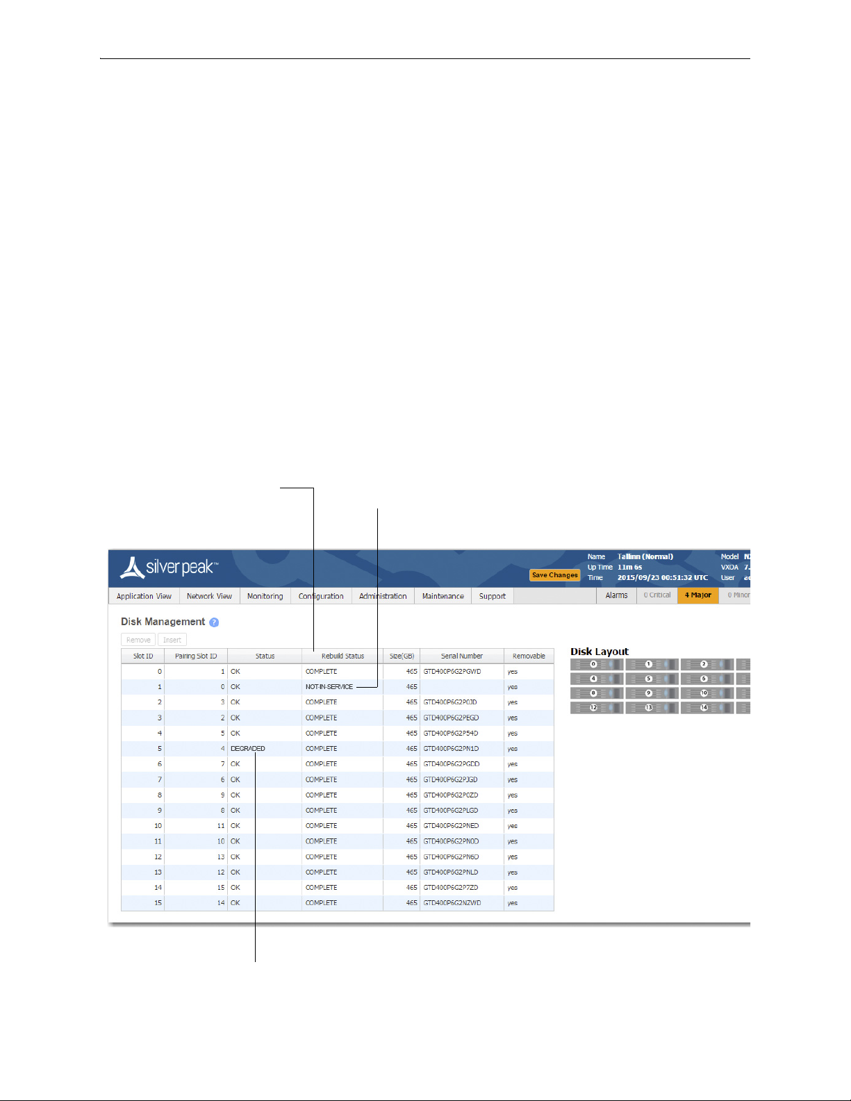
Displays the progress of a new disk that’s
being rebuilt from its array partner.
If a disk has been physically removed, the
Status is NOT-IN-SERVICE and no
Serial Number displays.
If a disk’s Status is DEGRADED, you
need to Remove it from the database,
Using Appliance Manager
The appliances use RAID arrays with encrypted disks. RAID stands for Redundant Array of Independent
(or Inexpensive) Disks, a category of disk drives that ensures recoverability by mirroring data on paired
hard drives.
Disk failure results in a critical alarm, and the specific disk’s LED stops illuminating on the appliance.
Follow this procedure when replacing a failed disk:
1 Log into your Support portal account, and click
2 Complete the wizard, using the serial number of the appliance (not the disk).
3 After you receive the new disk, go to the
4 Select the failed disk's row in the table and click
5 Physically remove the old disk from the appliance.
6 Physically insert the new disk.
7 In the table, select the new disk and click
Open a Self Service RMA for disk replacement.
Maintenance - Disk Management page.
Remove. This takes the disk off-line.
Insert. This prompts the software to discover the disk and
put it online.
2 PN 200972-001 Rev B

Physically Replacing a Disk Chapter 1 Replacing an HDD or SSD
Physically Replacing a Disk
This section provides the model-specific procedures for using Appliance Manager to replace an HDD or
SSD.
HDD or SSD
Part
Model
EC-XS 200889 1 no -- --
EC-S 200877 1 no -- --
EC-M 200890 2 yes yes “Disk Instruction Set A” on page 5
EC-L 200883 2 yes yes “Disk Instruction Set A” on page 5
EC-L-NM 200887 8 yes yes “Disk Instruction Set A” on page 5
EC-XL 200884 2 yes yes “Disk Instruction Set A” on page 5
EC-XL-NM 200888 6 yes yes “Disk Instruction Set A” on page 5
NX-700 200849 1 no -- --
NX-1700 AC 200404 1 no -- --
NX-1700 AC 200576 1 no -- --
NX-1700 200863 1 no -- --
NX-1700 DC 200464 1 no -- --
NX-2600 200178 1 no -- --
NX-2610 200193 2 yes no “Disk Instruction Set F” on page 16
NX-2700 200401 2 yes yes “Disk Instruction Set C” on page 10
Number
Allow user
to replace
Hot
swappable
Where to findQty
NX-2700 200697 2 yes yes “Disk Instruction Set A” on page 5
NX-3600 200348 2 yes no “Disk Instruction Set E” on page 15
NX-3700 200400 2 yes yes “Disk Instruction Set C” on page 10
NX-3700 200698 2 yes yes “Disk Instruction Set A” on page 5
NX-5600 200231 8 yes yes “Disk Instruction Set D” on page 13
NX-5700 200399 8 yes yes “Disk Instruction Set C” on page 10
NX-5700 200699 8 yes yes “Disk Instruction Set A” on page 5
NX-6700 200828 8 yes yes “Disk Instruction Set A” on page 5
NX-7600 200225 12 yes yes “Disk Instruction Set D” on page 13
NX-7700 200398 10 yes yes “Disk Instruction Set C” on page 10
NX-7700 200702 8 yes yes “Disk Instruction Set A” on page 5
NX-8600 200181 16 yes yes “Disk Instruction Set D” on page 13
NX-8700
NX-8700 200767 14 yes yes “Disk Instruction Set B” on page 8
NX-8700 200879 8 yes yes “Disk Instruction Set A” on page 5
a
200397 14 yes yes “Disk Instruction Set C” on page 10
PN 200972-001 Rev B 3

Silver Peak Hardware Reference Guide Physically Replacing a Disk
HDD or SSD
Model
Part
Number
Allow user
to replace
Hot
swappable
Where to findQty
NX-9610 200362 16 yes yes “Disk Instruction Set D” on page 13
NX-9700
a
200396 14 yes yes “Disk Instruction Set C” on page 10
NX-9700 200768 14 yes yes “Disk Instruction Set B” on page 8
NX-9700 200880 8 yes yes “Disk Instruction Set A” on page 5
NX-10700 200519 18 yes yes “Disk Instruction Set C” on page 10
NX-10700 200769 18 yes yes “Disk Instruction Set B” on page 8
NX-10700 200881 6 yes yes “Disk Instruction Set A” on page 5
NX-11700 200711 18 yes yes “Disk Instruction Set B” on page 8
NX-11700 200882 6 yes yes “Disk Instruction Set A” on page 5
a. Two disk configurations — regular and “v”
4 PN 200972-001 Rev B
Physically Replacing a Disk Chapter 1 Replacing an HDD or SSD
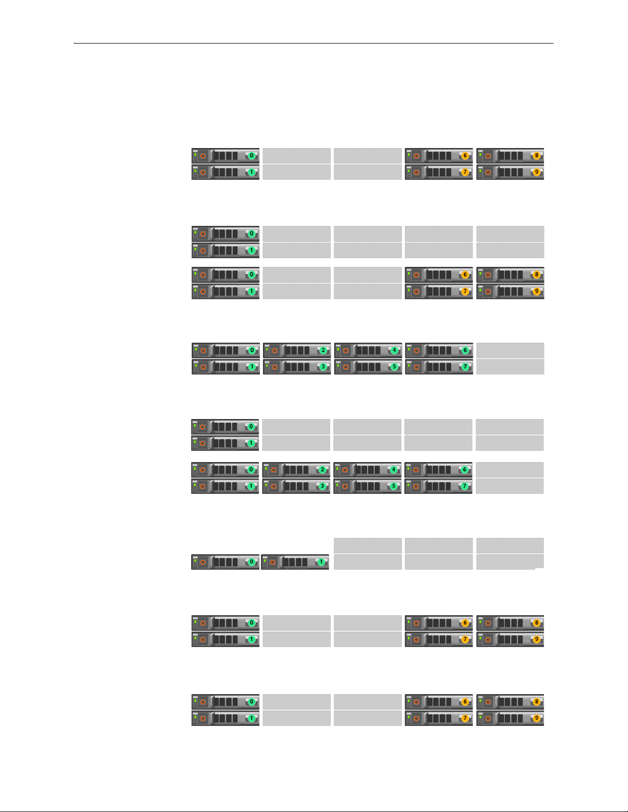
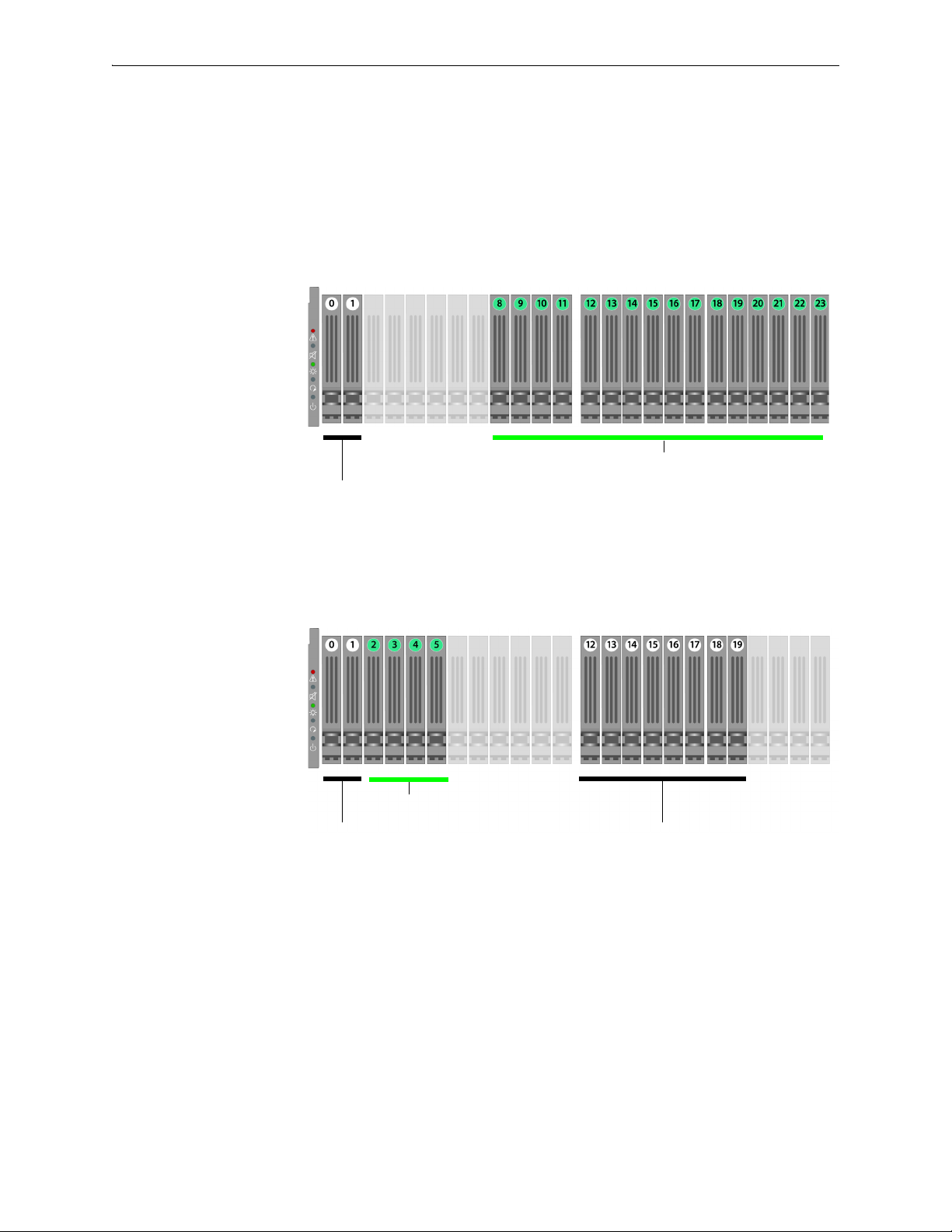
Disk Instruction Set A
These appliances’ drives are hot-swappable.
The first disk on the left is Disk 0. The numbers increment by one from left to right.
EC-XL-NM
[PN 200888]
Drives: 2 SSD + 4 NVMe
EC-XL
[PN 200884]
Drives:
Default = 2 SSD
Optional = 2 SSD + up to
4 NVMe
EC-L-NM
[PN 200887]
Drives: 8 SSD
EC-L
[PN 200883]
Drives:
Default = 2 SSD
Optional = up to 8 SSD
EC-M
[PN 200890]
Drives: 2 SSD
NX-11700
[PN 200882]
Drives: 2 SSD + 4 NVMe
NX-10700
[PN 200881]
Drives: 2 SSD + 4 NVMe
PN 200972-001 Rev B 5
Silver Peak Hardware Reference Guide Physically Replacing a Disk
Status
Activity
Drive online
NX-9700
[PN 200880]
Drives: 8 SSD
NX-8700
[PN 200879]
Drives: 8 SSD
NX-7700
[PN 200702]
Drives: 8 SSD
NX-6700
[PN 200828]
Drives: 8 SSD
NX-5700
[PN 200699]
Drives: 8 SSD
NX-3700
[PN 200698]
Drives: 2 SSD
NX-2700
[PN 200697]
Drives: 2 SSD
1 To take the disk off-line, go to the Maintenance - Disk Management page, select the disk, and click
Remove.
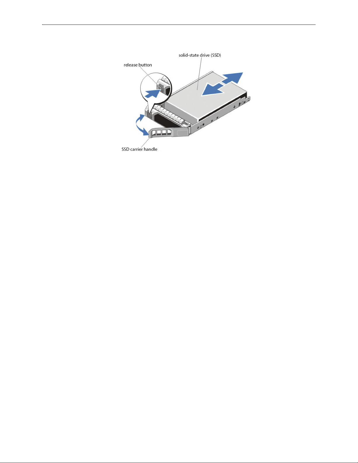
If the SSD is online, the green activity/fault indicator flashes as the drive
is turned off. When the SSD indicators are off, the SSD is ready for
removal.
6 PN 200972-001 Rev B

Physically Replacing a Disk Chapter 1 Replacing an HDD or SSD
2 Press the release button to open the SSD carrier release handle.
3 Slide the SSD carrier out until it is free of the hard-drive slot.
4 Press the release button on the front of the SSD carrier and open the SSD carrier handle.
5 Insert the SSD carrier into the SSD slot until the carrier connects with the backplane.
6 Close the SSD carrier handle to lock the SSD in place.
7 To put the disk back online, go to the
click
Insert.
Maintenance - Disk Management page, select the disk, and
PN 200972-001 Rev B 7

Silver Peak Hardware Reference Guide Physically Replacing a Disk
Status
Activity
Drive online
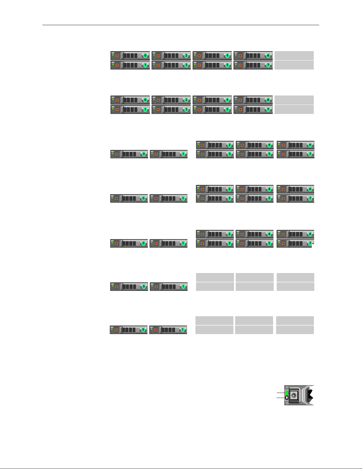
Disk Instruction Set B
These appliances’ drives are hot-swappable.
The first disk on the left is Disk 0. The numbers increment by one from left to right.
NX-11700
[PN 200711]
Drives: 18 SSD
NX-10700
[PN 200769]
Drives: 18 SSD
NX-9700
[PN 200768]
Drives: 14 SSD
NX-8700
[PN 200767]
Drives: 14 SSD
1 To take the disk off-line, go to the
Remove.
Maintenance - Disk Management page, select the disk, and click
If the SSD is online, the green activity/fault indicator flashes as the drive
is turned off. When the SSD indicators are off, the SSD is ready for
removal.
8 PN 200972-001 Rev B
Physically Replacing a Disk Chapter 1 Replacing an HDD or SSD
2 Press the release button to open the SSD carrier release handle.
3 Slide the SSD carrier out until it is free of the SSD slot.
4 Press the release button on the front of the SSD carrier and open the SSD carrier handle.
5 Insert the SSD carrier into the SSD slot until the carrier connects with the backplane.
6 Close the SSD carrier handle to lock the SSD in place.
7 To put the SSD online, go to the
Insert.
Maintenance - Disk Management page, select the disk, and click
PN 200972-001 Rev B 9
Silver Peak Hardware Reference Guide Physically Replacing a Disk
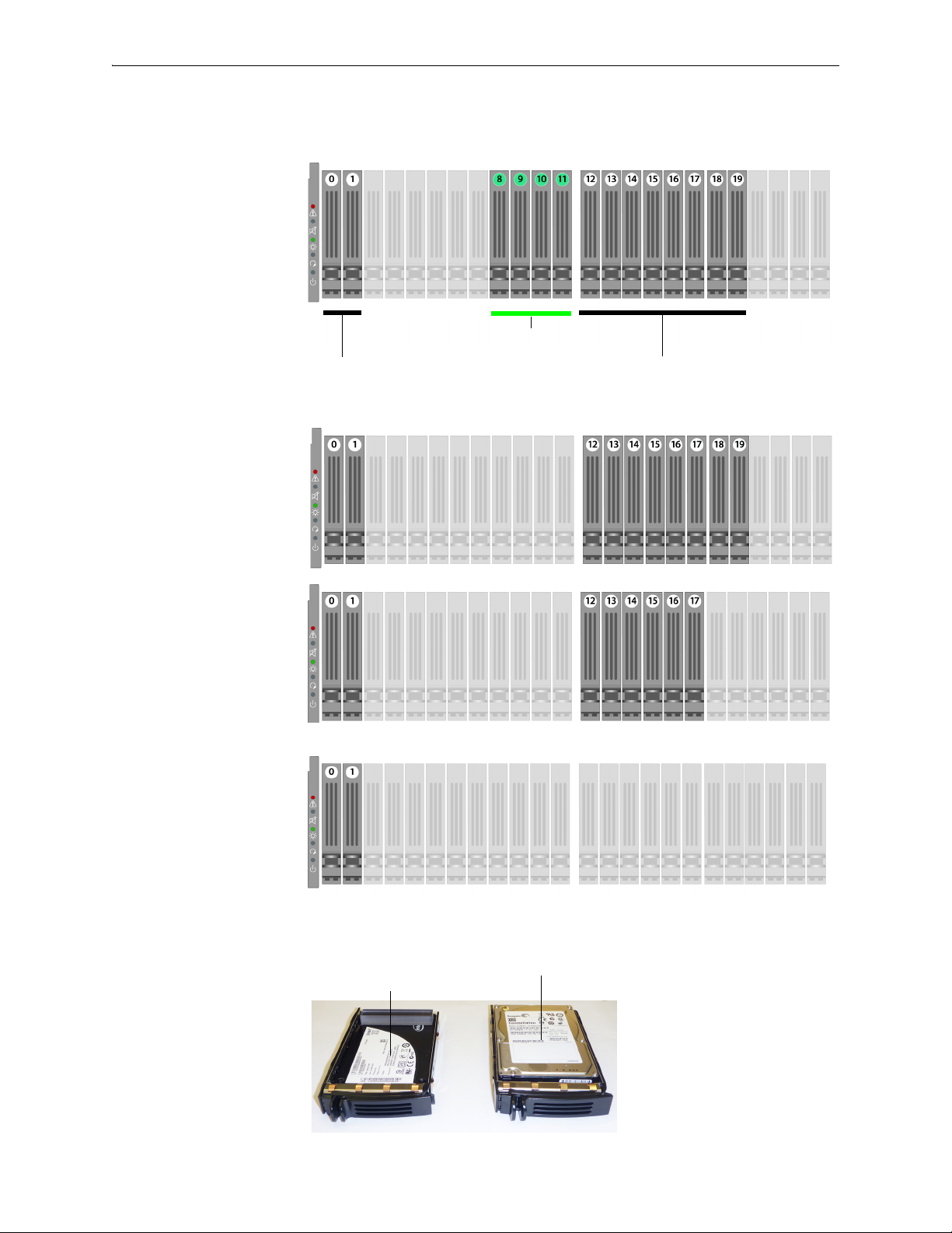
Solid-state disks
SATA hard
disk drives
Note that the NX-10700 appliances contain a mix of SATA
hard disk drives and SSDs (solid-state drives).
Solid-state disks
SATA hard
disk drives
SATA hard
disk drives
Note that the NX-9700 and NX-8700 appliances contain a mix
of SATA hard disk drives and SSDs (solid-state drives).
Disk Instruction Set C
The first disk on the left is Disk 0. The numbers increment by one from left to right.
These appliances’ hard disks are hot-swappable.
The NX-9700 and NX-8700 have two possible backplane configurations. The newer revision was
released in March 2011.
NX-10700
[PN 200519]
Drives: 2 HDD + 16 SSD
NX-9700
[PN 200396]
NX-8700
[PN 200397]
Drives: 10 HDD + 4 SSD
Release -001
10 PN 200972-001 Rev B
Physically Replacing a Disk Chapter 1 Replacing an HDD or SSD
Solid-state disks
SATA hard
disk drives
SATA hard
disk drives
Note that the NX-9700 and NX-8700 appliances contain a mix
of SATA hard disk drives and SSDs (solid-state drives).
Solid-state drive (SSD)
with spacer
SATA hard disk drive
NX-9700
[PN 200396]
NX-8700
[PN 200397]
Drives: 10 HDD + 4 SSD
Release -002
· March 2011 ·
NX-7700
[PN 200398]
Drives: 10 HDD
NX-5700
[PN 200399]
Drives: 8 HDD
NX-3700
[PN 200400]
NX-2700
[PN 200401]
Drives: 2 HDD
These are the two types of disk drives:
PN 200972-001 Rev B 11

Silver Peak Hardware Reference Guide Physically Replacing a Disk
Pinch the latch together. Grasp the tab and pull forward to release.
Push the top of the disk inward until it clicks into place. Push the latch against the tray to secure it.
1 To take the disk off-line, go to the Maintenance - Disk Management page, select the disk, and click
Remove.
2 Unlatch the carrier by pinching the latch together and then pulling the tab towards yourself.
3 Pull the disk out of its slot.
4 Insert the new disk and push until it clicks into place.
5 To put the disk back online, go to the
click
Insert.
Maintenance - Disk Management page, select the disk, and
The hard drive powers up.
12 PN 200972-001 Rev B
Physically Replacing a Disk Chapter 1 Replacing an HDD or SSD
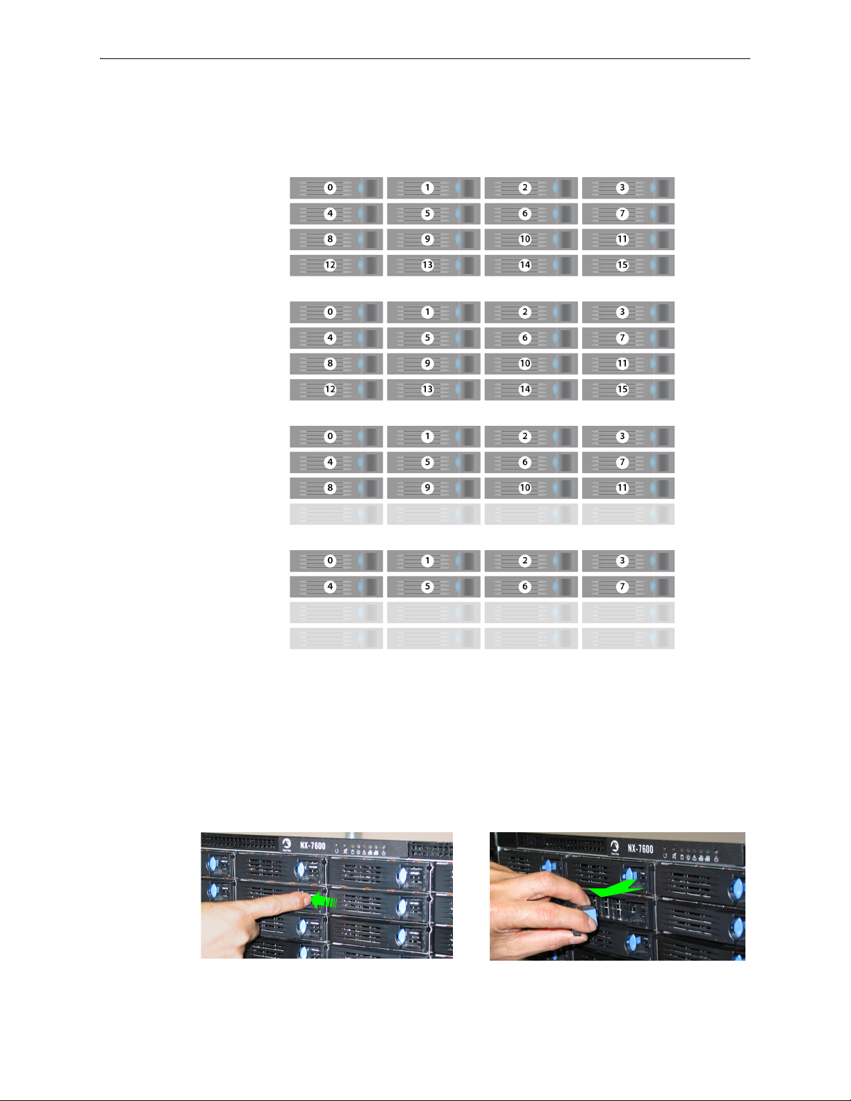
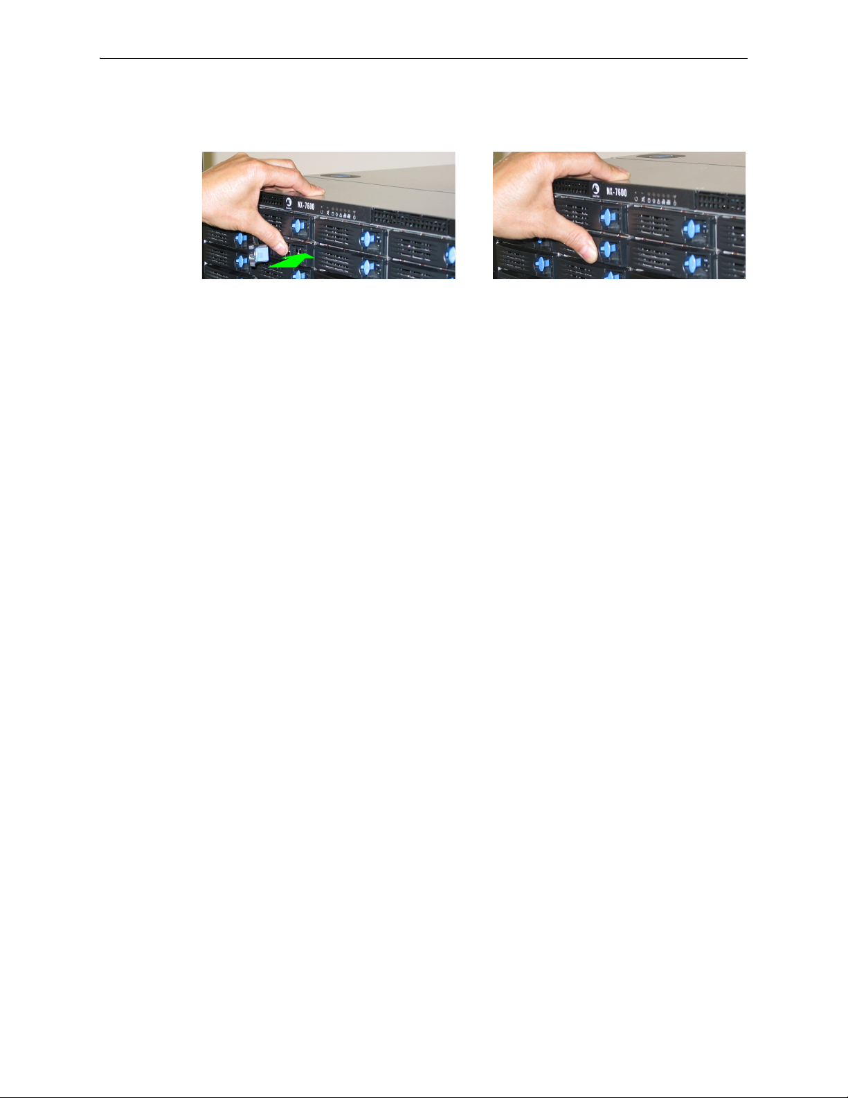
Depress the blue button leftward, into the tab. Slip your finger behind the tab and pull
forward to release.
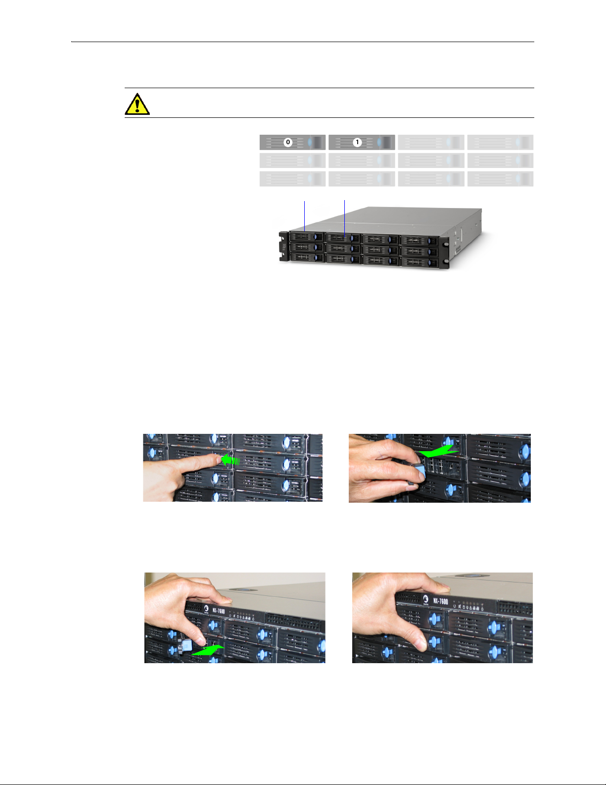
Disk Instruction Set D
These appliances’ disk drives are hot-swappable.
The first disk on the left is Disk 0. The numbers increment by one from left to right.
NX-9610
[PN 200362]
Drives: 16 HDD
NX-8600
[PN 200181]
Drives: 16 HDD
NX-7600
[PN 200225]
Drives: 12 HDD
NX-5600
[PN 200231]
Drives: 8 HDD
1 To take the disk off-line, go to the
Remove.
Maintenance - Disk Management page, select the disk and click
2 Unlatch the hard drive by pressing the end of the blue button toward the left and then pulling the tab
towards yourself.
3 Pull the disk out of its slot.
PN 200972-001 Rev B 13
Silver Peak Hardware Reference Guide Physically Replacing a Disk
Push the tray inward until it clicks into place. Push the tab against the tray to secure it.
4 Insert the new disk and push until it clicks into place.
5 To put the disk back online, go to the
Insert.
The drive powers up.
Maintenance - Disk Management page, select the disk and click
14 PN 200972-001 Rev B
Physically Replacing a Disk Chapter 1 Replacing an HDD or SSD
Disk 0 Disk 1
NX-3600
[PN 200348]
Drives: 2 HDD
Depress the blue button leftward, into the tab. Slip your finger behind the tab and pull
forward to release.
Although these photos show the NX-7600, the physical motions required to remove and re-insert the
disks are accurate for the NX-3600.
Push the tray inward until it clicks into place. Push the tab against the tray to secure it.
Disk Instruction Set E
CAUTION The NX-3600’s hard disks are NOT hot-swappable.
1 To take the disk off-line, go to the Maintenance - Disk Management page, select the disk, and click
Remove.
2 Power down the appliance by going to the
Shutdown.
Maintenance - Restart System page and clicking
3 After the NX appliance powers down, unlatch the hard drive by pressing the end of the blue button
toward the left and then pulling the tab towards yourself.
4 Pull the disk out of its slot.
5 Insert the new disk and push until it clicks into place.
PN 200972-001 Rev B 15
6 Power up the appliance by pressing the
7 To put the disk back online, go to the
Insert.
Maintenance - Disk Management page, select the disk and click
Power button on the front left side of the appliance.
Silver Peak Hardware Reference Guide Physically Replacing a Disk
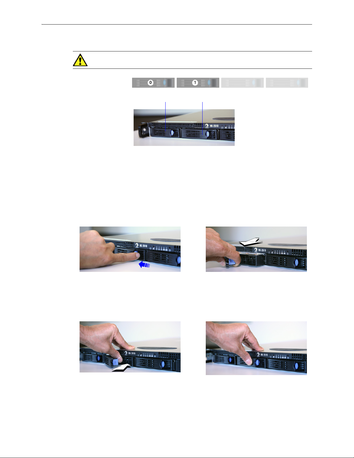
Disk 0 Disk 1
NX-2610
[PN 200193]
Drives: 2 HDD
Depress the blue button leftward, into the tab.
Slip your finger behind the tab and pull
forward to release.
Push the tray inward until it clicks into place.
Push the tab against the tray to secure it.
Disk Instruction Set F
CAUTION The NX-2610’s hard disks are NOT hot-swappable.
1 To take the disk off-line, go to the Maintenance - Disk Management page, select the disk, and click
Remove.
2 Power down the appliance by going to the
Shutdown.
Maintenance - Restart System page and clicking
3 After the drive powers down, unlatch the hard drive by pressing the end of the blue button toward
the left and then pulling the tab towards yourself.
4 Pull the disk out of its slot.
5 Insert the new disk and push until it clicks into place.
16 PN 200972-001 Rev B
6 Power up the appliance.
7 To put the disk back online, go to the
Insert.
Maintenance - Disk Management page, select the disk and click
CHAPTER 2
Replacing a Power Supply
This chapter describes how to replace a power supply for those appliances for which the customer is
authorized to make the replacement.
CAUTION Silver Peak does NOT authorize the customer to replace the power supplies in the
EC-XS, EC-S, NX-700, NX-1700, NX-2600, or NX-2610. Replacing it voids the warranty.
WARNING Do not open the casing of a power supply. Opening the casing of a power supply
voids the warranty. Only a qualified technician from the manufacturer has the authority to access
and/or service power supplies.
In This Chapter
Power Supply Instruction Set A See page 19.
Power Supply Instruction Set B See page 20.
Power Supply Instruction Set C See page 21.
PN 200972-001 Rev B 17

Silver Peak Hardware Reference Guide
The following table summarizes information about replacing redundant power supplies in authorized
appliance models:
Power Supplies
Model
Part
Number
Allow user
to replace
Hot
swappable
Where to findQty
EC-M 200890 2 yes yes “Power Supply Instruction Set A” on page 19
EC-L 200883 2 yes yes “Power Supply Instruction Set A” on page 19
EC-L-NM 200887 2 yes yes “Power Supply Instruction Set A” on page 19
EC-XL 200884 2 yes yes “Power Supply Instruction Set A” on page 19
EC-XL-NM 200888 2 yes yes “Power Supply Instruction Set A” on page 19
NX-2700 200401 2 yes yes “Power Supply Instruction Set C” on page 21
NX-2700 200697 2 yes yes “Power Supply Instruction Set A” on page 19
NX-3600 200348 2 yes yes “Power Supply Instruction Set C” on page 21
NX-3700 200400 2 yes yes “Power Supply Instruction Set C” on page 21
NX-3700 200698 2 yes yes “Power Supply Instruction Set A” on page 19
NX-5600 200231 3 yes yes “Power Supply Instruction Set C” on page 21
NX-5700 200399 2 yes yes “Power Supply Instruction Set C” on page 21
NX-5700 200699 2 yes yes “Power Supply Instruction Set A” on page 19
NX-6700 200828 2 yes yes “Power Supply Instruction Set A” on page 19
NX-7600 200225 3 yes yes “Power Supply Instruction Set C” on page 21
NX-7700 200398 2 yes yes “Power Supply Instruction Set C” on page 21
NX-11700 200702 2 yes yes “Power Supply Instruction Set A” on page 19
NX-8600 200181 3 yes yes “Power Supply Instruction Set C” on page 21
NX-8700
a
200397 2 yes yes “Power Supply Instruction Set C” on page 21
NX-8700 200767 2 yes yes “Power Supply Instruction Set B” on page 20
NX-8700 200879 2 yes yes “Power Supply Instruction Set A” on page 19
NX-9610 200362 3 yes yes “Power Supply Instruction Set C” on page 21
NX-9700
a
200396 2 yes yes “Power Supply Instruction Set C” on page 21
NX-9700 200768 2 yes yes “Power Supply Instruction Set B” on page 20
NX-9700 200880 2 yes yes “Power Supply Instruction Set A” on page 19
NX-10700 200519 2 yes yes “Power Supply Instruction Set C” on page 21
NX-10700 200769 2 yes yes “Power Supply Instruction Set B” on page 20
NX-10700 200881 2 yes yes “Power Supply Instruction Set A” on page 19
NX-11700 200711 2 yes yes “Power Supply Instruction Set B” on page 20
200882 2 yes yes “Power Supply Instruction Set A” on page 19
a. Two disk configurations — regular and “v”
18 PN 200972-001 Rev B
Power Supply Instruction Set A Chapter 2 Replacing a Power Supply
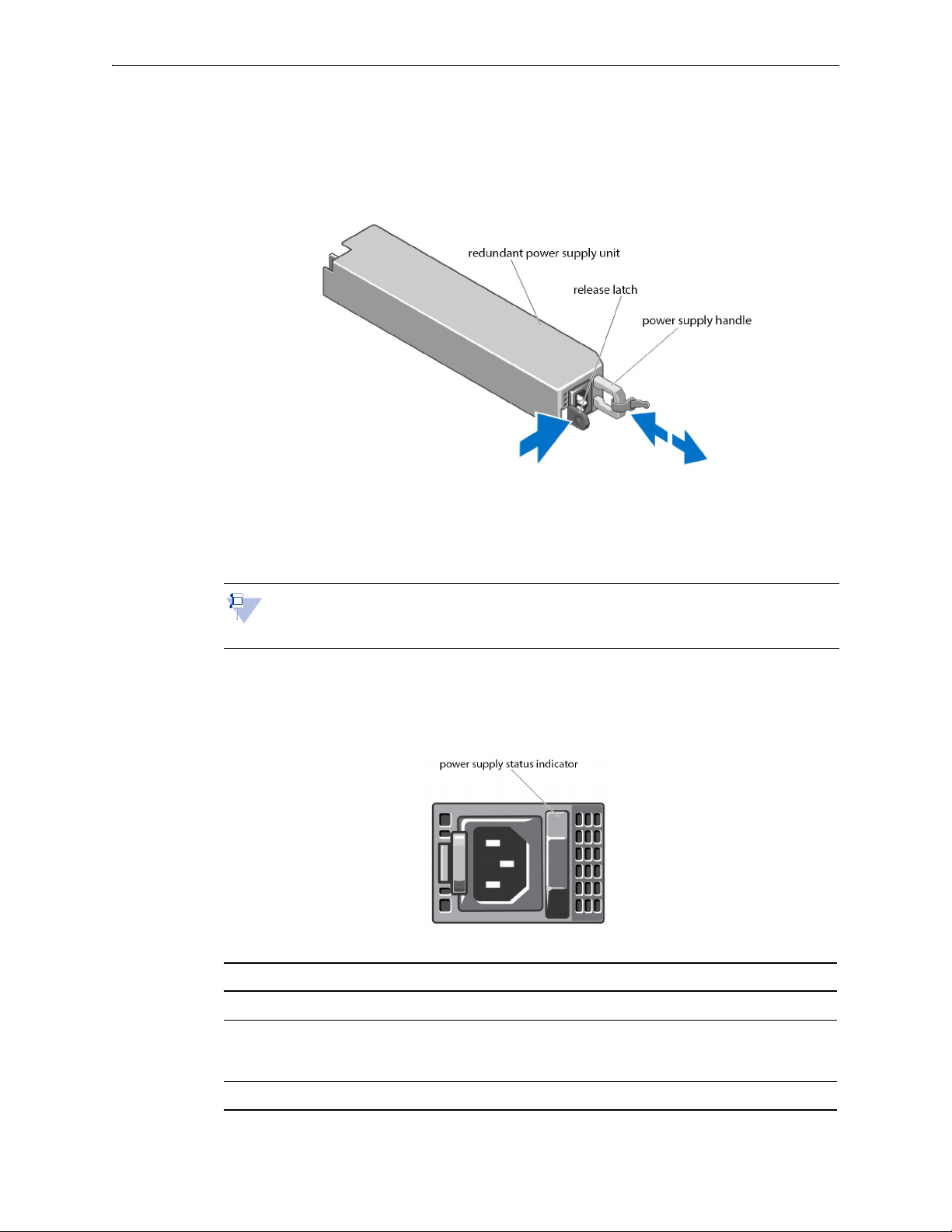
Power Supply Instruction Set A
1 Disconnect the power cable from the power source and the power supply you intend to remove.
2 Press the release latch and pull the power supply straight out to release it from the power distribution
board and clear the chassis.
3 Slide the new power supply into the chassis until the power supply is fully seated and the release
latch snaps into place.
4 Connect the power cable to the power supply and plug the cable into a power outlet.
Note When hot-swapping a new power supply, allow several seconds for the system to
recognize the power supply and determine its status. The power-supply status indicator turns
green to signify that the power supply is functioning properly.
Power Indicator Codes
Each power supply has an illuminated translucent handle that serves as an indicator to show whether
power is present or whether a power fault has occurred.
Power Indicator Pattern Condition
Not lit Power is not connected.
Green The handle/LED indicator illuminates green to indicate that a valid power
source is connected to the power supply and that the power supply is
operational.
Flashing amber Indicates a problem with the power supply. Contact Silver Peak Support.
PN 200972-001 Rev B 19
Silver Peak Hardware Reference Guide Power Supply Instruction Set B
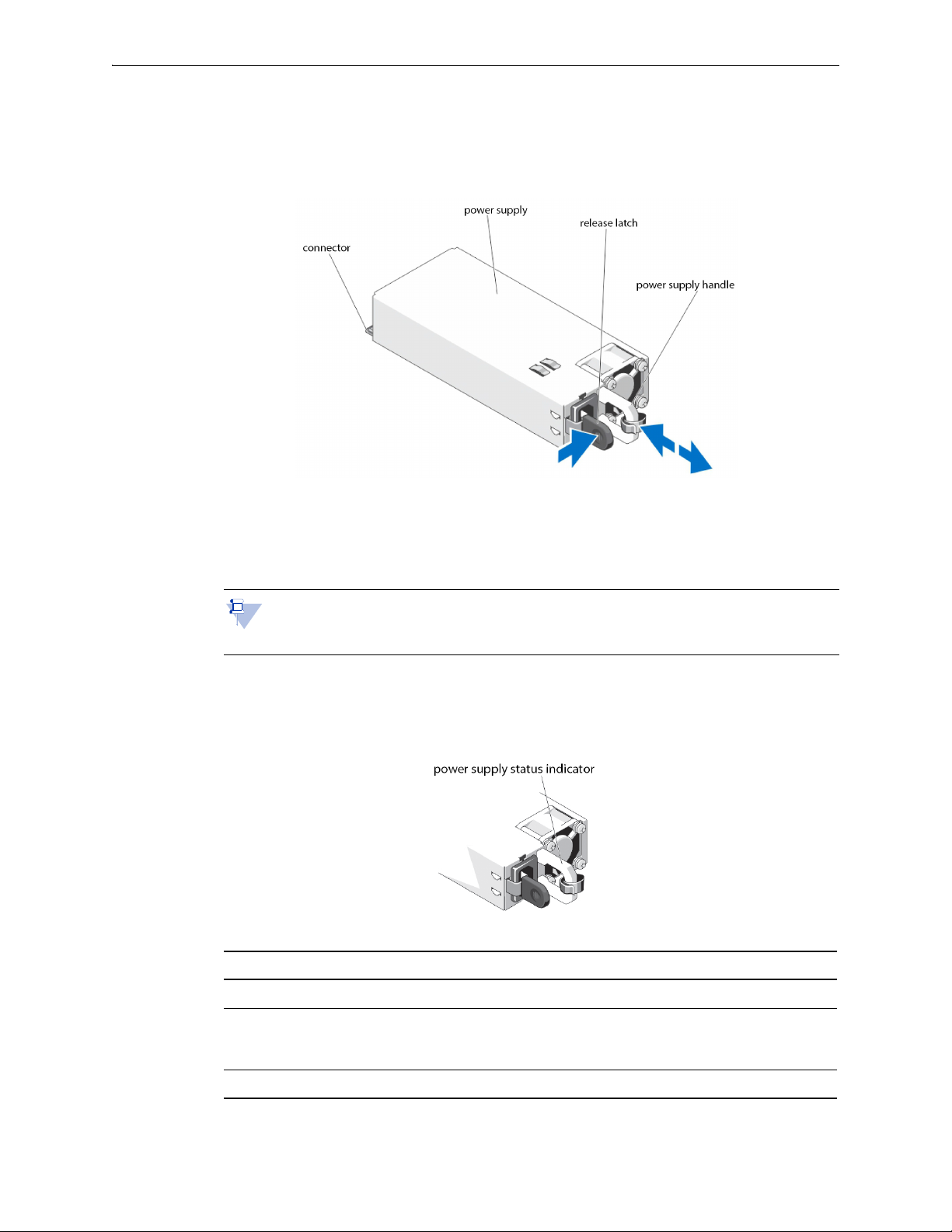
Power Supply Instruction Set B
1 Disconnect the power cable from the power source and the power supply you intend to remove.
2 Press the release latch and slide the power supply out of the chassis.
3 Slide the new power supply into the chassis until the power supply is fully seated and the release
latch snaps into place.
4 Connect the power cable to the power supply and plug the cable into a power outlet.
Note When hot-swapping a new power supply, allow several seconds for the system to
recognize the power supply and determine its status. The power-supply status indicator turns
green to signify that the power supply is functioning properly.
Power Indicator Codes
Each power supply has an illuminated translucent handle that serves as an indicator to show whether
power is present or whether a power fault has occurred.
Power Indicator Pattern Condition
Not lit Power is not connected.
Green The handle/LED indicator illuminates green to indicate that a valid power
source is connected to the power supply and that the power supply is
operational.
Flashing amber Indicates a problem with the power supply. Contact Silver Peak Support.
20 PN 200972-001 Rev B

Power Supply Instruction Set C Chapter 2 Replacing a Power Supply
2. To release the power supply from its
locking position, squeeze the screw
and the release tab together. Then
hold it there while you ....
1. Turn the screw counter-clockwise to loosen it.
3. ...grip the handle to remove
the power supply from the
chassis.
4. Once the power supply
module is released from its
locking position, remove it
from the chassis.
The
release
tab
Power Supply Instruction Set C
CAUTION Unplug the power cord before removing the power supply!!!
Note The photos are of the NX-x600 series. The power supplies in the NX-x700 appliances
look recognizably similar.
The NX-3600 power supplies are oriented 90° counterclockwise from these photos.
To access the power supply
Locate the release tab on the right side of the power supply.
PN 200972-001 Rev B 21
To insert a new power supply, repeat the procedure in reverse.

Silver Peak Hardware Reference Guide Power Supply Instruction Set C
22 PN 200972-001 Rev B
CHAPTER 3
Replacing a Fiber Interface Module
The following fiber-interface appliance models with have the option to separately order LR (Long
Reach) 10 Gbps Fiber Interfaces to replace the default SR (Short Reach) modules:
Model Part Number
NX-11700 200711
NX-10700 200519
NX-10700 200769
NX-9700 200768
NX-9700 200396
For the models listed above, Silver Peak supports different module combinations. For example, you
may have an SR (Short Reach) interface for the LAN side and an LR (or Long Reach) for the WAN.
These modules are hot-swappable.
This chapter describes how to replace the modules.
WARNING If you don’t turn off the power while replacing the module, be sure to protect your
eyes from exposure to the laser by being careful to avoid looking directly into the interface
housing.
PN 200972-001 Rev B 23
Silver Peak Hardware Reference Guide
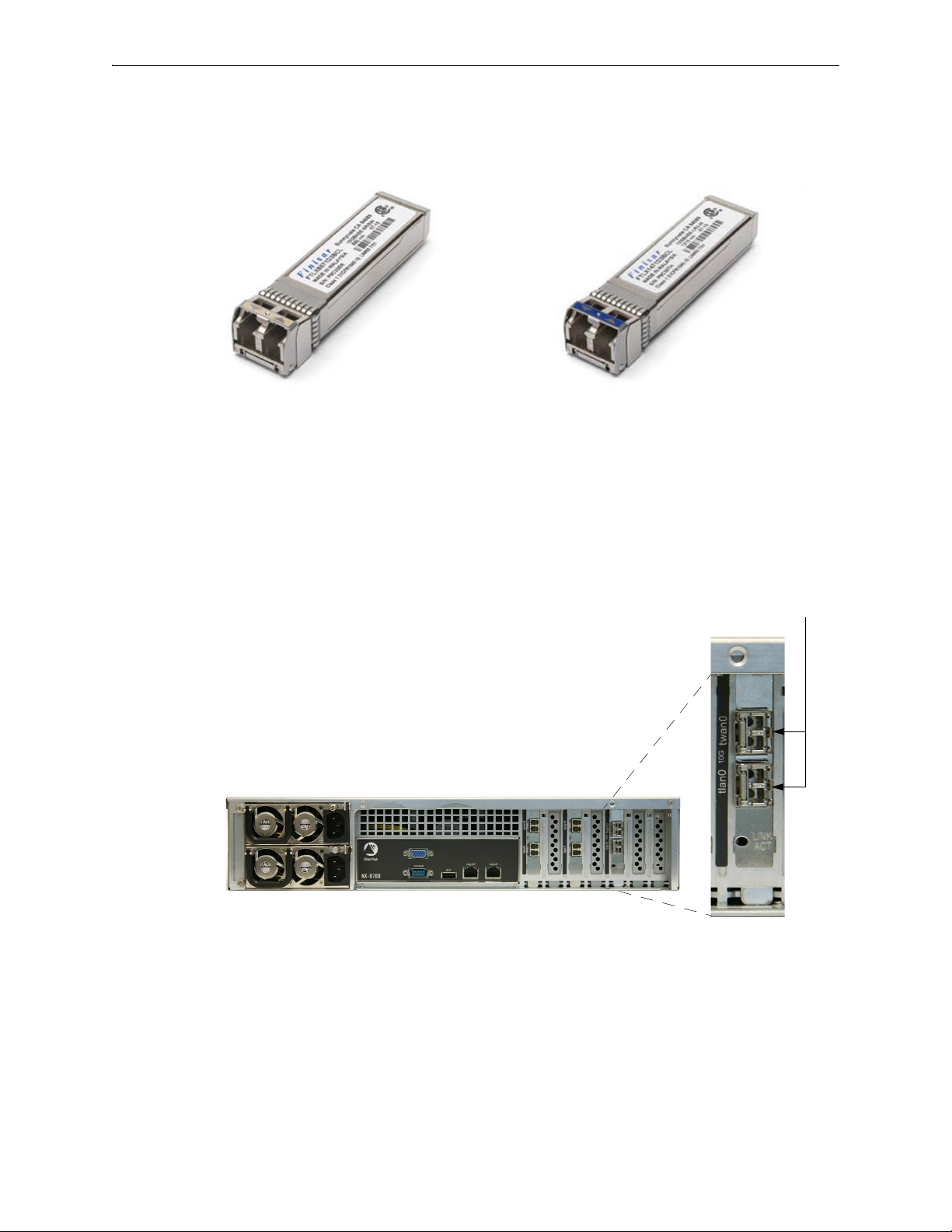
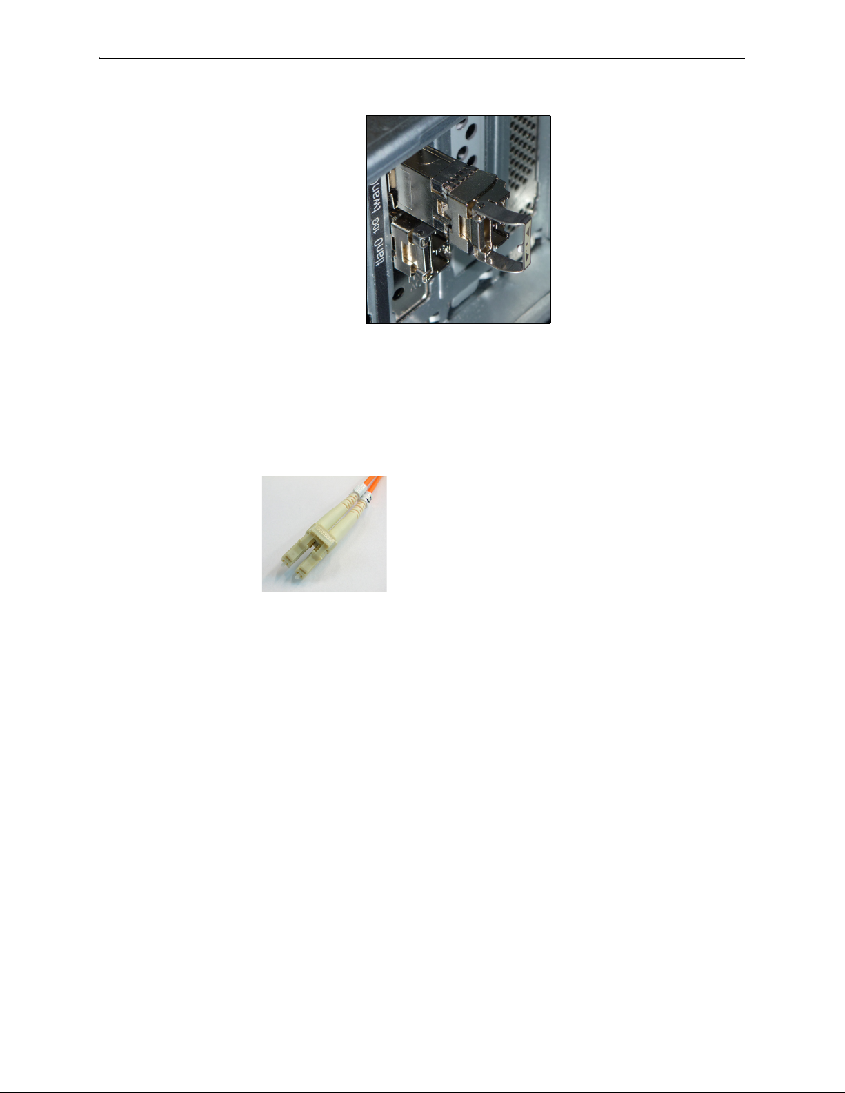
Module’s handle is on the right side.
You can distinguish the SR module from the LR module by the number on the label and the color of the
handle.
FTLX8571D3BCL — SR — Short Reach
• Bail (handle) is beige
• Default shipping module
To replace a fiber interface module
1 Locate the fiber interface(s).
FTLX1471D3BCL — LR — Long Range
• Bail (handle) is blue
• Optional, separate purchase
24 PN 200972-001 Rev B
Chapter 3 Replacing a Fiber Interface Module
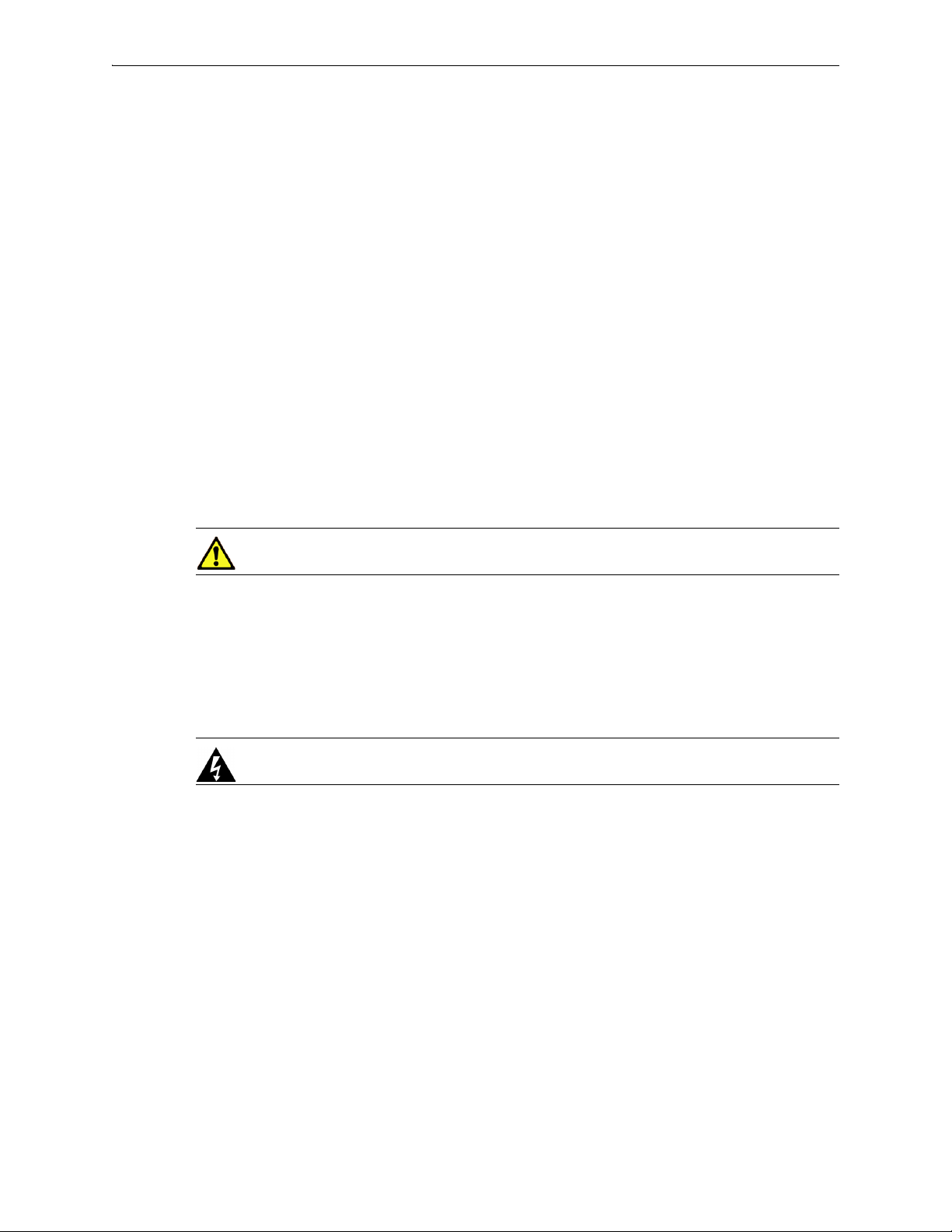
multimode duplex Fibre Channel optic
LC/LC patch cable
2 Lift the handle and rotate it 90 degrees to the left to release the module from its locking position.
3 Pull the handle to remove the module from the chassis.
4 To insert a new module, repeat the procedure in reverse. The module is fully seated when you hear
a click.
Each of these modules accepts the following fiber cable:
PN 200972-001 Rev B 25

Silver Peak Hardware Reference Guide
26 PN 200972-001 Rev B

CHAPTER 4
Replacing a Deployed Appliance
This chapter provides a checklist for replacing a deployed physical appliance with a new one.
In This Chapter
What to Consider See page 28.
System Replacement Procedure See page 28.
PN 200972-001 Rev B 27

Silver Peak Hardware Reference Guide What to Consider
What to Consider
The following bullets summarize information about using the Appliance Manager or Orchestrator when
replacing an appliance in an already deployed network:
• If you’ve made a backup of the appliance configuration, you’ll be able to restore it to the new
appliance. If not, you must manually configure the new appliance.
To manually configure the appliance, refer to the following user documents:
• Silver Peak Appliance Manager Operator’s Guide [200030-001]
• Silver Peak Unity Orchestrator User’s Guide [200095-001]
• If you’re replacing a 4-port appliance and want to restore the backup configuration, then make
sure that the new appliance is also a 4-port appliance.
System Replacement Procedure
1 Before removing the installed appliance, look at its configuration and write down the mgmt0 IP
addresses / netmask
2 If you haven’t backed up the configuration, do it now, using either the Appliance Manager or the
Orchestrator.
• When Access Manager creates a backup, the destination is the appliance itself. From there, you
can download it to your computer. So, make sure you have a copy outside of the appliance.
• The Orchestrator backs up appliances to the Orchestrator database.
3 Power down, disconnect, and remove the old appliance.
4 Physically install the new [replacement] appliance.
If you need to review rack mount instructions, refer to Silver Peak’s User Documentation web page.
5 Using the appropriate instructions, cable the appliance and configure the new appliance, as directed.
• For NX appliances, refer to the NX Series Quick Start Guide [PN 200257-001].
• For EdgeConnect appliances, refer to the Unity EdgeConnect Quick Start Guide
[PN 200907-001].
6 Make sure that the software revision in the new appliance is the same as in the replaced appliance:
• If the previous appliance was at a higher software revision, upgrade the new appliance to that
revision.
• If the previous appliance was at a lower software revision, call Customer Support for assistance.
and mgmt0 next-hop IP address.
7 Restore the backup configuration to the new appliance.
28 PN 200972-001 Rev B

CHAPTER 5
Specifications, Compliance, and Regulatory Statements
This chapter contains specifications, as well as compliance and regulatory statements.
In This Chapter
Model Specifications See page 30.
Warning Statements See page 40.
Compliance Statements See page 44.
PN 200972-001 Rev B 29

Silver Peak Hardware Reference Guide Model Specifications
Model Specifications
This section includes general and model-specific specifications for the Silver Peak appliances:
Model-specific Specifications See page 30.
Fiber Specifications See page 38.
EdgeConnect (EC) Series and NX-Series Specifications See page 39.
Note To verify the most current VXOA host system requirements, refer to the Quick Start
Guides listed in the User Documentation section of http://www.silver-peak.com/Support.
Note To see which hypervisors Silver Peak’s VXOA software currently supports, refer to the
Quick Start Guides listed in the User Documentation section of
http://www.silver-peak.com/Support.
Model-specific Specifications
EC-XS
[PN 200889]
Capacity WAN Capacity
(All Features)
Local Data Store 1 x 120 GB SSD 2 x 480 GB SSD 2 x 480 GB SSD
Connectivity LAN/WAN
Power Requirement 100–240VAC 50–60Hz,
Dimensions
and Weight
Ethernet
Management 2 x 10/100/1000;
Power Supplies Single Single 1+1 redundant
Height 1.7 in. (44 mm) 1.73 in. (44 mm) 1.69 in. (43 mm) 1 RU
Width 9.4 in. (240 mm) 16.97 in. (431 mm) 17.1 in. (434 mm)
2 – 200 Mbps 10 – 1000 Mbps 50 – 2000 Mbps
4 x 10/100/1000 LAN
WAN
RJ-45 serial port
23 W / 78.5 BTU
EC-S
[PN 200877]
6 x 10/100/1000 LAN
WAN
Optional 2 x 1/10 Gbps
fiber LAN WAN
2 x 10/100/1000;
RJ-45 serial port
100–240VAC 47–63Hz,
100 W / 341BTU
EC-M
[PN 200890]
4 x 10/100/1000 LAN
WAN; 2 x 1/10 Gbps
fiber LAN WAN
2 x 10/100/1000;
RJ-232 serial port
100–240VAC 50–60Hz,
126 W / 430 BTU
Depth 6.5 in. (166 mm) 12.01 in. (305 mm) 26.1 in. (663 mm)
Weight 3.0 lbs (1.4 kg) 11.0 lbs (5.0 kg) 26.0 lbs (11.8 kg)
30 PN 200972-001 Rev B

Model Specifications Chapter 5 Specifications, Compliance, and Regulatory Statements
EC-L
[PN 200883]
Capacity WAN Capacity
(All Features)
Local Data Store 2 x 480 GB SSD 8 x 480 GB SSD 2 x 480 GB SSD
Connectivity LAN/WAN
Power Requirement 100–240VAC 50–60Hz,
Dimensions
and Weight
Ethernet
Management 2 x 10/100/1000;
Power Supplies 1+1 redundant 1+1 redundant 1+1 redundant
Height 1.69 in. (42.8 mm) 1 RU 1.69 in. (42.8 mm) 1 RU 1.69 in. (42.8 mm) 1 RU
Width 17.34 in. (440.51 mm) 17.34 in. (440.51 mm) 17.34 in. (440.51 mm)
Depth 28.57 in. (725.80 mm) 28.57 in. (725.80 mm) 28.57 in. (725.80 mm)
Weight 36.0 lbs (16.3 kg) 36.0 lbs (16.3 kg) 36.0 lbs (16.3 kg)
1 – 5 Gbps 1 – 5 Gbps 2 – 10 Gbps
4 x 10/100/1000 LAN
WAN; 2 x 1/10 Gbps
fiber LAN WAN
RJ-232 serial port
401 W / 1368 BTU
EC-L-NM
[PN 200887]
4 x 10/100/1000 LAN
WAN; 2 x 1/10 Gbps
fiber LAN WAN
2 x 10/100/1000;
RJ-232 serial port
100–240VAC 50–60Hz,
440 W / 1501 BTU
EC-XL
[PN 200884]
4 x 1/10 Gbps fiber LAN
WAN
2 x 10/100/1000;
RJ-232 serial port
100–240VAC 50–60Hz,
474 W / 1617 BTU
EC-XL-NM
[PN 200888]
Capacity WAN Capacity
Connectivity LAN/WAN
Power Requirement 100–240VAC 50–60Hz,
Dimensions
and Weight
(All Features)
Local Data Store 2 x 480 GB SSD
Ethernet
Management 2 x 10/100/1000;
Power Supplies 1+1 redundant
Height 1.69 in. (42.8 mm) 1 RU
Width 17.34 in. (440.51 mm)
Depth 28.57 in. (725.80 mm)
Weight 36.0 lbs (16.3 kg)
2 – 10 Gbps
4 x 400 GB NVMe SSD
4 x 1/10 Gbps fiber LAN
WAN
RJ-232 serial port
537 W / 1832 BTU
PN 200972-001 Rev B 31

Silver Peak Hardware Reference Guide Model Specifications
NX-700
[PN 200849]
Capacity WAN Capacity
(All Features)
Local Data Store 1 x 120GB SSD 1 x 500 GB HDD 1 x 500 GB HDD
Connectivity LAN/WAN
Power Requirement 100–240VAC 50–60Hz,
Dimensions
and Weight
Ethernet
Management 2 x 10/100/1000;
Power Supplies Single Single Single
Height 1.7 in. (44 mm) 1.8 in. (45 mm) 1 RU 1.75 in. (44.4 mm) 1 RU
Width 9.4 in. (240 mm) 17.5 in. (445 mm) 16.9 in. (430 mm)
Depth 6.5 in. (166 mm) 8.2 in. (209 mm) 10.9 in. (277 mm)
Weight 3.0 lbs (1.4 kg) 8.5 lbs (3.9 kg) 8.8 lbs (4.0 kg)
2 Mbps 4 Mbps 4 Mbps
4 x 10/100/1000 LAN
WAN
RJ-45 serial port
23 W / 78.5 BTU
NX-1700
[PN 200404]
4 x 10/100/1000 LAN
WAN
2 x 10/100/1000;
RS-232 serial port
100–240VAC 47–63Hz,
90 W / 307 BTU
NX-1700
[PN 200576]
4 x 10/100/1000 LAN
WAN
2 x 10/100/1000;
RS-232 serial port
90–240VAC 47–63Hz,
46 W / 157 BTU
NX-1700
[PN 200863]
Capacity WAN Capacity
(All Features)
Local Data Store 1 x 240 GB SSD 1 x 500 GB HDD
Connectivity LAN/WAN
Power Requirement 100–240VAC
Dimensions
and Weight
Ethernet
Management 2 x 10/100/1000;
Power Supplies Single Single
Height 1.7 in. (44 mm) 1.8 in. (45 mm) 1 RU
Width 9.4 in. (240 mm) 17.5 in. (445 mm)
Depth 6.5 in. (166 mm) 8.2 in. (209 mm)
Weight 3.0 lbs (1.4 kg) 8.5 lbs (3.9 kg)
4 Mbps 4 Mbps
4 x 10/100/1000 LAN
WAN
RJ-45 serial port
50–60Hz, 23 W / 78.5
BTU
NX-1700 DC
[PN 200464]
4 x 10/100/1000 LAN
WAN
2 x 10/100/1000;
RS-232 serial port
-31VDC to -72VDC,
86 W / 295 BTU
32 PN 200972-001 Rev B

Model Specifications Chapter 5 Specifications, Compliance, and Regulatory Statements
NX-2600
[PN 200178]
Capacity WAN Capacity
(All Features)
Local Data Store 1 x 250 GB HDD 2 x 250 GB HDD
Connectivity LAN/WAN
Power Requirement 100–240VAC 50-60Hz,
Dimensions
and Weight
Ethernet
Management 2 x 10/100/1000;
Power Supplies Single Single
Height 1.7 in. (43.5 mm) 1 RU 1.7 in. (43.5 mm) 1 RU
Width 16.9 in. (430 mm) 16.9 in. (430 mm)
Depth 22.4 in. (569 mm) 22.4 in. (569 mm)
Weight 22.0 lbs (10.0 kg) 24.2 lbs (11.0 kg)
4 Mbps 8 Mbps
2 x 10/100/1000 LAN
WAN
RS-232 serial port
145 W / 496 BTU
NX-2610
[PN 200193]
4 x 10/100/1000 LAN
WAN
2 x 10/100/1000;
RS-232 serial port
100–240VAC 50-60Hz,
165 W / 563 BTU
NX-2700
[PN 200401]
Capacity WAN Capacity
Connectivity LAN/WAN
Power Requirement 100–240VAC 47-63Hz,
Dimensions
and Weight
(All Features)
Local Data Store 2 x 500 GB HDD 2 x 240 GB SSD 2 x 500 GB HDD
Ethernet
Management 2 x 10/100/1000;
Power Supplies 1+1 redundant 1+1 redundant 1+1 redundant
Height 3.5 in. (89 mm) 2 RU 1.69 in. (43 mm) 1 RU 3.5 in. (89 mm) 2 RU
Width 16.9 in. (430 mm) 17.1 in. (434 mm) 17.0 in. (432 mm)
Depth 26 in. (660 mm) 26.1 in. (663 mm) 26.0 in. (661 mm)
Weight 40.5 lbs (18.4 kg) 24.0 lbs (10.8 kg) 41.0 lbs (18.6 kg)
10 Mbps 10 Mbps 20 Mbps
4 x 10/100/1000 LAN
WAN
RS-232 serial port
285 W / 973 BTU
NX-2700
[PN 200697]
4 x 10/100/1000 LAN
WAN
2 x 10/100/1000;
RS-232 serial port
100–240VAC 50-60Hz,
94 W / 321 BTU
NX-3600
[PN 200348]
4 x 10/100/1000 LAN
WAN
2 x 10/100/1000;
RS-232 serial port
100–240VAC 47-63Hz,
250 W / 853 BTU
PN 200972-001 Rev B 33

Silver Peak Hardware Reference Guide Model Specifications
NX-3700
[PN 200400]
Capacity WAN Capacity
(All Features)
Local Data Store 2 x 500 GB HDD 2 x 240 GB SSD 8 x 250 GB HDD
Connectivity LAN/WAN
Power Requirement 100–240VAC 47-63Hz,
Dimensions
and Weight
Ethernet
Management 2 x 10/100/1000;
Power Supplies 1+1 redundant 1+1 redundant 2+1 redundant
Height 3.5 in. (89 mm) 2 RU 1.69 in. (43 mm) 1 RU 5.2 in. (132 mm) 3 RU
Width 16.9 in. (430 mm) 17.1 in. (434 mm) 17 in. (432 mm)
Depth 26 in. (660 mm) 26.1 in. (663 mm) 26 in. (659 mm)
Weight 40.5 lbs (18.4 kg) 24.0 lbs (18.4 kg) 62 lbs (28.1 kg)
20 Mbps 20 Mbps 50 Mbps
4 x 10/100/1000 LAN
WAN
RS-232 serial port
305 W / 1041 BTU
NX-3700
[PN 200698]
4 x 10/100/1000 LAN
WAN
2 x 10/100/1000;
RS-232 serial port
100–240VAC 50-60Hz,
94 W / 321 BTU
NX-5600
[PN 200231]
4 x 10/100/1000 LAN
WAN
2 x 10/100/1000;
RS-232 serial port
100–240VAC 50-60Hz,
440 W / 1501 BTU
NX-5700
[PN 200399]
Capacity WAN Capacity
(All Features)
Local Data Store 8 x 500 GB HDD 8 x 240 GB SSD 8 x 240 GB SSD
Connectivity LAN/WAN
Power Requirement 100–240VAC 47-63Hz,
Dimensions
and Weight
Ethernet
Management 2 x 10/100/1000;
Power Supplies 1+1 redundant 1+1 redundant 1+1 redundant
Height 3.5 in. (89 mm) 2 RU 1.69 in. (43 mm) 1 RU 1.69 in. (43 mm) 1 RU
Width 16.9 in. (430 mm) 17.1 in. (434 mm) 17.1 in. (434 mm)
Depth 26 in. (660 mm) 26.1 in. (663 mm) 26.1 in. (663 mm)
Weight 43 lbs (19.6 kg) 26.0 lbs (11.8 kg) 26.0 lbs (11.8 kg)
50 Mbps 50 Mbps 100 Mbps
4 x 10/100/1000 LAN
WAN
RS-232 serial port
345 W / 1178 BTU
NX-5700
[PN 200699]
4 x 10/100/1000 LAN
WAN
2 x 10/100/1000;
RS-232 serial port
100–240VAC 50-60Hz,
126 W / 430 BTU
NX-6700
[PN 200828]
4 x 10/100/1000 LAN
WAN
2 x 10/100/1000;
RS-232 serial port
100–240VAC 50-60Hz,
126 W / 430 BTU
34 PN 200972-001 Rev B

Model Specifications Chapter 5 Specifications, Compliance, and Regulatory Statements
NX-7600
[PN 200225]
Capacity WAN Capacity
(All Features)
Local Data Store 12 x 250 GB HDD 10 x 500 GB HDD 8 x 240 GB SSD
Connectivity LAN/WAN
Ethernet
Management 2 x 10/100/1000;
Power Requirement 100–240VAC 50-60Hz,
Power Supplies 2+1 redundant 1+1 redundant 1+1 redundant
Dimensions
and Weight
Height 5.2 in. (132 mm) 3 RU 3.5 in. (89 mm) 2 RU 1.69 in. (43 mm) 1 RU
Width 17 in. (432 mm) 16.9 in. (430 mm) 17.1 in. (434 mm)
Depth 26 in. (659 mm) 26 in. (660 mm) 26.1 in. (663 mm)
Weight 68 lbs (30.8 kg) 44 lbs (20 kg) 26.0 lbs (11.8 kg)
155 Mbps 200 Mbps 200 Mbps
4 x 10/100/1000 LAN
WAN
RS-232 serial port
580 W / 1979 BTU
NX-7700
[PN 200398]
4 x 10/100/1000 LAN
WAN
2 x 10/100/1000;
RS-232 serial port
100–240VAC 47-63Hz,
475 W / 1621 BTU
NX-7700
[PN 200702]
4 x 10/100/1000 LAN
WAN
2 x 10/100/1000;
RS-232 serial port
100–240VAC 50-60Hz,
126 W / 430 BTU
NX-8600
[PN 200181]
Capacity WAN Capacity
(All Features)
Local Data Store 16 x 500 GB HDD 10 x 500 GB HDD
Connectivity LAN/WAN
Power Requirement 100–240VAC 50-60Hz,
Dimensions
and Weight
Ethernet
Management 2 x 10/100/1000;
Power Supplies 2+1 redundant 1+1 redundant 1+1 redundant
Height 5.2 in. (132 mm) 3 RU 3.5 in. (89 mm) 2 RU 3.4 in. (87 mm) 2 RU
Width 17 in. (432 mm) 16.9 in. (430 mm) 17.5 in. (444 mm)
Depth 26 in. (659 mm) 26 in. (660 mm) 29.2 in. (741 mm)
Weight 75 lbs (34.0 kg) 46.5 lbs (21.2 kg) 47.5 lbs (21.4 kg)
500 Mbps 622 Mbps 622 Mbps
4 x 10/100/1000 LAN
WAN
RS-232 serial port
650 W / 2218 BTU
NX-8700
[PN 200397]
4 x 100 GB SSD
4 x 10/100/1000 LAN
WAN; 2 x 10 Gbps fiber
LAN WAN
2 x 10/100/1000;
RS-232 serial port
100-240VAC 47–63Hz,
520 W / 1775 BTU
NX-8700
[PN 200767]
14 x 240 GB SSD
4 x 10/100/1000 LAN
WAN; 2 x 10 Gbps fiber
LAN WAN
2 x 10/100/1000;
RS-232 serial port
100–240VAC 50-60Hz,
491 W / 1675 BTU
PN 200972-001 Rev B 35

Silver Peak Hardware Reference Guide Model Specifications
NX-8700
[PN 200879]
Capacity WAN Capacity
(All Features)
Local Data Store 8 x 480 GB SSD 16 x 500 GB HDD 10 x 500 GB HDD
Connectivity LAN/WAN
Ethernet
Management 2 x 10/100/1000;
Power Requirement 100–240VAC 50-60Hz,
Power Supplies 1+1 redundant 2+1 redundant 1+1 redundant
Dimensions
and Weight
Height 1.69 in. (42.8 mm) 1 RU 5.2 in. (132 mm) 3 RU 3.5 in. (89 mm) 2 RU
Width 17.34 in. (440.51 mm) 17 in. (432 mm) 16.9 in. (430 mm)
Depth 28.57 in. (725.80 mm) 26 in. (659 mm) 26 in. (660 mm)
Weight 36.0 lbs (16.3 kg) 75.5 lbs (34.5 kg) 47 lbs (21.2 kg)
622 Mbps 1 Gbps 1 Gbps
4 x 10/100/1000 LAN
WAN; 2 x 1/10 Gbps
fiber LAN WAN
RS-232 serial port
440 W / 1501 BTU
NX-9610
[PN 200362]
4 x 1 Gbps fiber LAN WAN;
2 x 10 Gbps fiber LAN WAN
2 x 10/100/1000;
RS-232 serial port
100–240VAC 50-60Hz,
682 W / 2327 BTU
NX-9700
[PN 200396]
4 x 100 GB SSD
4 x 1 Gbps fiber LAN WAN;
2 x 10 Gbps fiber LAN WAN
2 x 10/100/1000;
RS-232 serial port
100-240VAC 47–63Hz, 600
W / 2048 BTU
NX-9700
[PN 200768]
Capacity WAN Capacity
Connectivity LAN/WAN
Power Requirement 100–240VAC 50-60Hz,
Dimensions
and Weight
(All Features)
Local Data Store 14 x 240 GB SSD 8 x 480 GB SSD
Ethernet
Management 2 x 10/100/1000;
Power Supplies 1+1 redundant 1+1 redundant
Height 3.4 in. (87 mm) 2 RU 1.69 in. (42.8 mm) 1 RU
Width 17.5 in. (444 mm) 17.34 in. (440.51 mm)
Depth 29.2 in. (741 mm) 28.57 in. (725.80 mm)
Weight 47.5 lbs (21.4 kg) 36.0 lbs (16.3 kg)
1 Gbps 1 Gbps
4 x 1 Gbps fiber LAN WAN;
2 x 10 Gbps fiber LAN WAN
RS-232 serial port
493 W / 1682 BTU
NX-9700
[PN 200880]
4 x 10/100/1000 LAN WAN;
2 x 1/10 Gbps fiber LAN WAN
2 x 10/100/1000;
RS-232 serial port
100–240VAC 50-60Hz,
440 W / 1501 BTU
36 PN 200972-001 Rev B

Model Specifications Chapter 5 Specifications, Compliance, and Regulatory Statements
NX-10700
[PN 200519]
Capacity WAN Capacity
(All Features)
Local Data Store 2 x 500 GB HDD
Connectivity LAN/WAN
Ethernet
Management 2 x 10/100/1000;
Power Requirement 100-240VAC 47–63Hz, 600
Power Supplies 1+1 redundant 1+1 redundant 1+1 redundant
Dimensions
and Weight
Height 3.5 in. (89 mm) 2 RU 3.4 in. (87 mm) 2 RU 1.69 in. (42.8 mm) 1 RU
Width 16.9 in. (430 mm) 17.5 in. (444 mm) 17.34 in. (440.51 mm)
Depth 26 in. (660 mm) 29.2 in. (741 mm) 28.57 in. (725.80 mm)
Weight 46.5 lbs (21.1 kg) 48.5 lbs (22.0 kg) 36.0 lbs (16.3 kg)
2.5 Gbps 2.5 Gbps 2.5 Gbps
16 x 100 GB SSD
4 x 10 Gbps fiber LAN WAN 4 x 10 Gbps fiber LAN WAN 4 x 1/10 Gbps fiber LAN WAN
RS-232 serial port
W / 2048 BTU
NX-10700
[PN 200769]
18 x 100 GB SSD 2 x 480 GB SSD
2 x 10/100/1000;
RS-232 serial port
100–240VAC 50-60Hz,
590 W / 2013 BTU
NX-10700
[PN 200881]
4 x 400 GB NVMe SSD
2 x 10/100/1000;
RJ-232 serial port
100–240VAC 50–60Hz, 537
W / 1832 BTU
NX-11700
[PN 200711]
Capacity WAN Capacity
(All Features)
Local Data Store 18 x 100 GB SSD 2 x 480 GB SSD
Connectivity LAN/WAN
Ethernet
Management 2 x 10/100/1000;
Power Requirement 100–240VAC 50-60Hz,
Power Supplies 1+1 redundant 1+1 redundant
Dimensions
and Weight
Height 3.4 in. (87 mm) 2 RU 1.69 in. (42.8 mm) 1 RU
Width 17.5 in. (444 mm) 17.34 in. (440.51 mm)
Depth 29.2 in. (741 mm) 28.57 in. (725.80 mm)
Weight 48.5 lbs (22.0 kg) 36.0 lbs (16.3 kg)
5 Gbps 5 Gbps
4 x 10 Gbps fiber LAN WAN 4 x 1/10 Gbps fiber LAN WAN
RS-232 serial port
590 W / 2013 BTU
NX-11700
[PN 200882]
4 x 400 GB NVMe SSD
2 x 10/100/1000;
RJ-232 serial port
100–240VAC 50–60Hz, 537
W / 1832 BTU
PN 200972-001 Rev B 37

Silver Peak Hardware Reference Guide Model Specifications
Fiber Specifications
1 Gbps Fiber Interfaces
NX-9610 / NX-9700
lan / wan
Fiber Support
•4 interfaces
• LC connectors
• Multi-mode 50
fiber
a. This can be for lan0/wan0 or lan1/wan1.
• 2 interfaces
• LC connectors
a
μ fiber / 62.5μ
NX-10700 / NX-11700: 10 Gbps Fiber Interfaces
10 Gbps Fiber Interfaces
NX-8700 / NX-9610 / NX-9700
a
lan / wan
Fail-to-Close
NX-9610 — no • 2 interfaces
NX-9700 — yes
tlan0 / twan0 / tlan1 / twan1 Fiber Support
• LC connectors
• Multi-mode 50
• SR (Short Reach) modules (default)
10 Gb/s 850 nm Multimode Datacom SFP+
Transceiver
• LR (Long Reach) modules
10 Gb/s 10 km Single Mode Datacom SFP+
Transceiver
• Multi-mode 50
• Fail-to-close — no
• SR (Short Reach) modules (default)
10 Gb/s 850 nm Multimode Datacom SFP+ Transceiver
• LR (Long Reach) modules
10 Gb/s 10 km Single Mode Datacom SFP+ Transceiver
μ fiber
tlan0 / twan0
Fiber Support
μ fiber
tlan0 / twan0
Fail-to-Close
no
Hardware
Model (2015) Part Number
NX-8700
NX-9700
EC-M
EC-L
EC-L-NM
NX-11700
EC-XL
EC-XL-NM
PN 200879
PN 200880
PN 200890
PN 200883
PN 200887
PN 200881
PN 200882
PN 200884
PN 200888
• 2 interfaces
• LC connectors
• 4 interfaces
• LC connectors
1/10 Gbps Fiber Interfaces
tlan0 / twan0 / tlan1 / twan1 Fiber Support
• Multi-mode 50
•Fail-to-close — yes
• SR (Short Reach) modules
1/10 Gb/s 850 nm Multimode Datacom SFP+ TransceiverNX-10700
μ fiber
38 PN 200972-001 Rev B

Model Specifications Chapter 5 Specifications, Compliance, and Regulatory Statements
EdgeConnect (EC) Series and NX-Series Specifications
Environmental Temperature (Operating) 10°C to 35°C (50°F to 95°F)
Temperature (Storage) -40°C to 65°C (-40°F to 149°F)
Humidity 8% to 90% relative humidity, non-condensing
Altitude (Operating) Up to 10,000 ft. (3,048 m)
Altitude (Storage) Up to 40,000 ft. (12,192 m)
Regulatory EMC FCC Part 15 Class A, EN 55022 Class A,
Safety UL/cUL 60950, EN 60950
EN 61000-3-2/3-3, EN 55024
PN 200972-001 Rev B 39
Silver Peak Hardware Reference Guide Warning Statements
Warning Statements
Class 1 Laser Products
NX-8700 EC-S (only with optional fiber module)
NX-9600 EC-M
NX-9700 EC-L
NX-10700 EC-L-NM
NX-11700 EC-XL
EC-XL-NM
Maintenance Port Precautions
The serial console is only used for periodic maintenance and not to be used under normal operation.
General Safety
CAUTION Please note the following:
1 The server will not be used in a home, school or other public area where the general population
would have access to it.
2 The manufacturer specifies that the thumbscrew normally should be tightened with a screwdriver.
Use of a thumbscrew is not considered to compromise the basic principles of safety associated with
the standard.
WARNING To prevent potential for personal injury, property damage or death, please
observe the following instructions:
• Do not use damaged equipment, including exposed, frayed or damaged power cords. Use only
the approved power cable that is rated for the equipment. The voltage and current rating of the
cable should be greater than the ratings marked on the equipment.
• Plug the power cables into properly grounded electrical outlets
• Do not use adapter plugs or remove the grounding prong from a cable.
If you must use an extension cable, use a 3-wire cable with properly grounded plugs.
• Observe extension cable and power strip ratings to ensure that the total ampere rating of all
equipment plugged into the extension cable or power strip does not exceed 80 percent of the
ampere ratings limit for the extension cable or power strip.
• When connecting or disconnecting power to hot-swappable power supplies, observe the
following precautions:
• Install the power supply before connecting the power cable to it.
• Unplug the power cable before removing a power supply.
40 PN 200972-001 Rev B

Warning Statements Chapter 5 Specifications, Compliance, and Regulatory Statements
• To disconnect power from the server, disconnect all power cables from all power supplies.
(If you only disconnect one hot-swappable power supply, the system will automatically
switch to a redundant one.)
• The power supplies in the server may produce high voltages and potential energy hazards. By
opening the cover of the server you may be exposed to a risk of electric shock. The components
inside the server housing should only be serviced by a trained service technician.
• Inside the housing, the power supply may have more than one power supply cable. To reduce
the risk of electric shock, a trained service technician may need to disconnect all power supply
cables before servicing the system.
• The server should not be operated with the cover removed.
• Components inside the server housing may become extremely hot during normal operations.
These components include the memory and CPU modules. Allow sufficient time for
components to cool before handling.
• The server should not be operated in environments that can get wet. Protect the server at all
times from liquid intrusion.
• If your server gets wet, turn off the AC power at the circuit breaker before attempting to remove
the power cables from the electrical outlet. Then disconnect power to the equipment and to any
attached devices.
• Avoid obstructing the air vents on the server or pushing objects into the openings. This could
lead to fire or electric shock.
CAUTION To prevent hardware damage or loss of data, observe the following precautions:
• Follow installation instructions carefully.
• Do not attempt to service the equipment yourself. The server should be serviced by a trained
service technician.
• You should operate this equipment from the type of external power source indicated on the
electrical ratings label.
• Wait 30 seconds after turning off the equipment before removing a component from the system
or disconnecting a peripheral device from the server.
• Always leave at least 4 inches (10.2cm) of physical clearance on all vented sides of the server.
This permits the airflow required for proper ventilation.
• Avoid placing equipment too close together such that it is subject to re-circulated (pre-heated)
air. Avoid placing equipment too close to an server or exhaust vent.
• Ensure that cables are connected to the server without stress and that nothing rests on the cables.
• If the equipment is located in a rack, move it with caution. Ensure that all casters and/or
stabilizers are firmly connected. While moving the equipment, avoid uneven surfaces and
sudden stops.
• Do not place other equipment, monitors, or other devices on top of the server.
• To protect the server from fluctuations in electrical power, use a surge suppressor, line
conditioner or uninterruptible power supply (UPS).
PN 200972-001 Rev B 41

Silver Peak Hardware Reference Guide Warning Statements
WARNING BATTERY WARNING: Installing an incompatible battery on the server board may
increase the risk of fire or explosion. Observe the following precautions:
• The battery should only be replaced with a battery that is the same or equivalent as the factory
installed battery.
• Do not attempt to open or service the battery. Do not dispose of the battery in a fire or with
household waste. Contact the local waste disposal agency for the location of the nearest battery
deposit site.
CAUTION Please observe the following additional precautions for rack-mounted systems:
• Slide/rail mounted equipment is not to be used as a shelf or a work space.
• Elevated Operating Ambient – If the server is installed in a closed or multi-unit rack assembly,
the operating ambient temperature in the rack environment may be greater than the room
ambient temperature. Therefore, consideration should be given to the maximum operating
temperature specified in the environmental specifications.
• Reduced Air Flow – Installation of the server in a rack should be such that the amount of air
flow required for safe operation is not compromised.
• Mechanical Loading – Mounting of the server in the rack should not create a hazardous
condition from uneven mechanical loading.
• Circuit Overloading – Connection of the equipment to the supply circuit should not create an
overloaded situation. Pay close attention to equipment nameplate ratings.
• Reliable Grounding – Appliances mounted in racks should be grounded properly. If using
power strips to connect the server to the supply circuit, make certain that the power strips are
also grounded properly.
• It is your responsibility to ensure that the rack and the provided rail system are compatible with
each other before installing the server.
• Install the front and side stabilizers prior to installing equipment in a rack. Failure to install
stabilizers may cause a rack to tip over.
• Load racks from the bottom up, loading the heaviest items near the bottom of the rack.
• Do not stand or step on components in the rack.
• Do not use slide-rail-mounted equipment as a shelf or workspace. Do not add weight to the top
of the server.
WARNING Grounding Instructions for Qualified Electricians Only:
• Grounding techniques may vary. However, a positive connection to a safety (earth) ground is
required.
• Make the ground connection first and disconnect it last to prevent hazards.
• Never defeat the ground conductor or operate the equipment in the absence of a suitably
installed ground conductor.
42 PN 200972-001 Rev B

Warning Statements Chapter 5 Specifications, Compliance, and Regulatory Statements
• If the system is installed in a rack, ensure that the system chassis is securely grounded to the
rack cabinet frame. Do not connect power to the system until grounding cables are connected.
PN 200972-001 Rev B 43

Silver Peak Hardware Reference Guide Compliance Statements
Compliance Statements
This section includes the following required compliance statements:
FCC Compliance Statement See page 44.
ICES-003 statement See page 44.
Requirements for Rack-Mount Equipment See page 44.
Requirements for Knurled Thumb Screws See page 44.
FCC Compliance Statement
This equipment has been tested and found to comply with the limits for a Class A digital device, pursuant
to Part 15 of the FCC Rules. These limits are designed to provide reasonable protection against harmful
interference when the equipment is operated in a commercial environment. This equipment generates,
uses, and can radiate radio frequency energy and, if not installed and used in accordance with the
instruction manual, may cause harmful interference to radio communications. Operation of this
equipment in a residential area is likely to cause harmful interference in which case the user will be
required to correct the interference at his own expense.
ICES-003 statement
The Class A digital apparatus complies with Canadian ICES-003.
Cet appareil numérique de la classe A est conforme á la norme NMB-003 du Canada.
Requirements for Rack-Mount Equipment
Observe the following requirements for all rack-mount equipment:
1
Elevated Operating Ambient Temperature – If installed in a closed or multi-unit rack assembly, the
operating ambient temperature of the rack environment may be greater than room ambient.
Therefore, consideration should be given to installing the equipment in an environment compatible
with the maximum ambient temperature (Tma) specified by the manufacturer.
2
Reduced Air Flow – Installation of the equipment in a rack should be such that the amount of air flow
required for safe operation of the equipment is not compromised.
3
Mechanical Loading – Mounting of the equipment in the rack should be such that a hazardous
condition is not achieved due to uneven mechanical loading.
4
Circuit Overloading – Consideration should be given to the connection of the equipment to the
supply circuit and the effect that overloading of the circuits might have on overcurrent protection
and supply wiring.
Appropriate consideration of equipment nameplate ratings should be used when addressing this
concern.
5
Reliable Earthing – Reliable earthing of rack-mounted equipment should be maintained. Particular
attention should be given to supply connections other than direct connections to the branch circuit
(for example, use of power strips).
Requirements for Knurled Thumb Screws
When rack mounting an appliance, thumbscrews should be tightened with a tool after both initial
installation and subsequent access to the panel.
44 PN 200972-001 Rev B

CHAPTER 6
Appliance Views
This chapter includes each appliance model and provides information about its physical characteristics
and layout.
In This Chapter
Supported Inventory See page 47.
EC-XS [PN 200889] See page 49.
EC-S [PN 200877] See page 50.
EC-M [PN 200890] See page 51.
EC-L [PN 200883] See page 53.
EC-L-NM [PN 200887] See page 55.
EC-XL [PN 200884] See page 57.
EC-XL-NM [PN 200888] See page 59.
NX-700 [PN 200849] See page 61.
NX-1700 AC [PN 200404 and PN 200576] See page 62.
NX-1700 [PN 200863] See page 64.
NX-1700 DC [PN 200464] See page 65.
NX-2600 [PN 200178] / NX-2610 [PN 200193] See page 66.
NX-2700 [PN 200401] See page 67.
NX-2700 [PN 200697] See page 69.
NX-3600 [PN 200348] See page 70.
NX-3700 [PN 200400] See page 71.
NX-3700 [PN 200698] See page 73.
NX-5600 [PN 200231] See page 74.
NX-5700 [PN 200399] See page 76.
NX-5700 [PN 200699] See page 78.
NX-6700 [PN 200828] See page 79.
PN 200972-001 Rev B 45

Silver Peak Hardware Reference Guide
NX-7600 [PN 200225] See page 80.
NX-7700 [PN 200398] See page 82.
NX-7700 [PN 200702] See page 84.
NX-8600 [PN 200181] See page 85.
NX-8700 [PN 200397] See page 87.
NX-8700 [PN 200767] See page 91.
NX-8700 [PN 200879] See page 93.
NX-9610 [PN 200362] See page 95.
NX-9700 [PN 200396] See page 97.
NX-9700 [PN 200768] See page 100.
NX-9700 [PN 200880] See page 102.
NX-10700 [PN 200519] See page 104.
NX-10700 [PN 200769] See page 106.
NX-10700 [PN 200881] See page 108.
NX-11700 [PN 200711] See page 110.
NX-11700 [PN 200882] See page 112.
46 PN 200972-001 Rev B

Supported Inventory Chapter 6 Appliance Views
Supported Inventory
HDD/SSD Drives Power Supplies
Part
Model
Number
EC-XS 200889 1 no -- 0
Qty
Allow user
to replace
Hot
swappable
Qty
a
Allow user
to replace
N/A N/A
Hot
swappable
EC-S 200877 1 no -- 1 N/A N/A
EC-M 200890 2 yes yes 2 yes yes
EC-L 200883 2 yes yes 2 yes yes
EC-L-NM 200887 8 yes yes 2 yes yes
EC-XL 200884 2 yes yes 2 yes yes
EC-XL-NM 200888 6 yes yes 2 yes yes
NX-700 200849 1 no -- 0
b
N/A N/A
NX-1700 AC 200404 1 no -- 1 no --
NX-1700 AC 200576 1 no -- 1 no --
NX-1700 DC 200464 1 no -- 1 no --
NX-1700 200863 1 no -- 0
c
N/A N/A
NX-2600 200178 1 no -- 1 no --
NX-2610 200193 2 yes no 1 no --
NX-2700 200401 2 yes yes 2 yes yes
NX-2700 200697 2 yes yes 2 yes yes
NX-3600 200348 2 yes no 2 yes yes
NX-3700 200400 2 yes yes 2 yes yes
NX-3700 200698 2 yes yes 2 yes yes
NX-5600 200231 8 yes yes 3 yes yes
NX-5700 200399 8 yes yes 2 yes yes
NX-5700 200699 8 yes yes 2 yes yes
NX-6700 200828 8 yes yes 2 yes yes
NX-7600 200225 12 yes yes 3 yes yes
NX-7700 200398 10 yes yes 2 yes yes
NX-7700 200702 8 yes yes 2 yes yes
NX-8600 200181 16 yes yes 3 yes yes
NX-8700
d
200397 14 yes yes 2 yes yes
NX-8700 200767 14 yes yes 2 yes yes
NX-8700 200879 8 yes yes 2 yes yes
NX-9610 200362 16 yes yes 3 yes yes
NX-9700
e
200396 14 yes yes 2 yes yes
NX-9700 200768 14 yes yes 2 yes yes
PN 200972-001 Rev B 47

Silver Peak Hardware Reference Guide Supported Inventory
HDD/SSD Drives Power Supplies
Model
Part
Number
Qty
Allow user
to replace
Hot
swappable
Qty
Allow user
to replace
Hot
swappable
NX-9700 200880 8 yes yes 2 yes yes
NX-10700 200519 18 yes yes 2 yes yes
NX-10700 200769 18 yes yes 2 yes yes
NX-10700 200881 6 yes yes 2 yes yes
NX-11700 200711 18 yes yes 2 yes yes
NX-11700 200882 6 yes yes 2 yes yes
a. This model has a power adapter.
b. This model has a power adapter.
c. This model has a power adapter.
d. Two disk configurations — regular and “v”
e. Two disk configurations — regular and “v”
48 PN 200972-001 Rev B
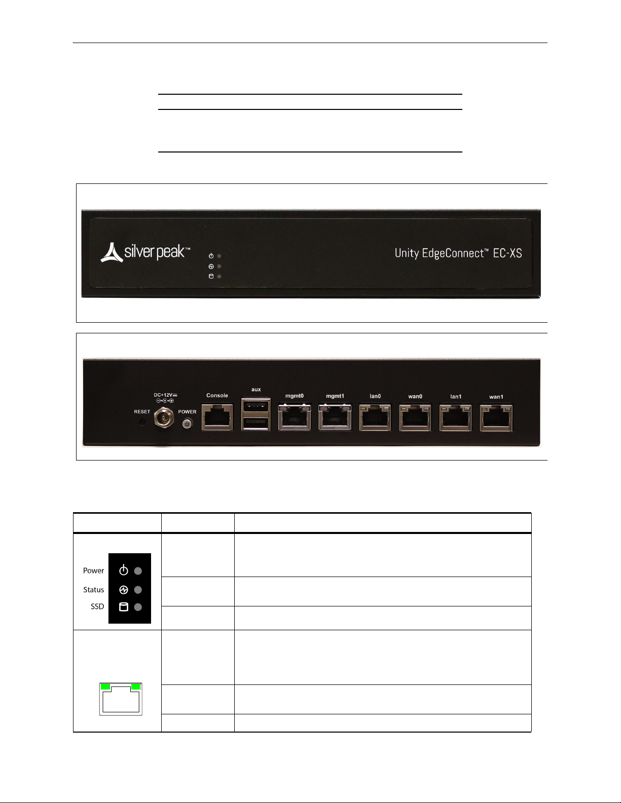
EC-XS [PN 200889] Chapter 6 Appliance Views
EC-XS — Front View
EC-XS— Rear View
Link/
Activity
Speed
EC-XS [PN 200889]
EC-XS SSD Power Adapter
Quantity 1 1
User authorized to replace? no N/A
Hot swappable? -- --
EC-XS
Front LEDs
LED
Power • Illuminated = System is powered on
• Not illuminated = System is powered off
Status • Green = Operational state is normal
• Red = System is malfunctioning
SSD • Blinking = Data access activities
Rear LEDs
PN 200972-001 Rev B 49
Speed • Amber = Connection speed is 1000 Mbps
• Green = Connection speed is 100 Mbps
• Not illuminated = Connection speed is 10 Mbps
Link/ACT • Amber solid= Port is active
• Amber blinking = There is traffic
Both LEDs • Not illuminated = BYPASS

Silver Peak Hardware Reference Guide EC-S [PN 200877]
Front View
With optional 1/10 Gbps fiber card
Rear View
Link/
Activity
Speed
EC-S [PN 200877]
EC-S SSD Power Supplies
Quantity 1 1
User authorized to replace? no N/A
Hot swappable? -- --
EC-S
50 PN 200972-001 Rev B
LED
Power • Illuminated = System is powered on
• Not illuminated = System is powered off
Status • Green = Operational state is normal
• Red = System is malfunctioning
SSD • Blinking = Data access activities
Speed • Amber = Connection speed is 1000 Mbps
• Green = Connection speed is 100 Mbps
• Not illuminated = Connection speed is 10 Mbps
Link/ACT • Amber solid= Port is active
• Amber blinking = There is traffic
Both LEDs • Not illuminated = BYPASS

EC-M [PN 200890] Chapter 6 Appliance Views
Front View
Power LED [green = ON]
Status
Activity
Drive online
Status
Activity
Drive failed
Status
Activity
Traffic
(4 blinks/sec)
Rear View
ActivityLink
ActivityLink
ActivityLink
ActivityLink
EC-M [PN 200890]
EC-M
SSD
Supplies Disk Layout
Quantity 2 2
User authorized to replace? yes yes
Hot swappable? yes yes
Power
mgmt0 & mgmt1
Not connected Connected at max speed Connected at lower speed Traffic
PN 200972-001 Rev B 51

Silver Peak Hardware Reference Guide EC-M [PN 200890]
Link/
Activity
Speed /
Bypass /
Disconnect
lan0 / wan0 / lan1 / wan1
Rear LEDs
LED
Speed / Bypass /
Disconnect
SPEED
• Yello w solid = Connection speed is 1000 Mbps
• Green solid = Connection speed is 100 Mbps
• Not illuminated = Connection speed is 10 Mbps
Bypass/Disconnect
• Green blinking = Bypass
• Yello w blinking = Disconnect
Link/ACT • Green solid= Port is active
• Green blinking = There is traffic
1/10 Gbps fiber interfaces for tlan / twan
a
Indicator 10G 1G
LNK Link blue solid green solid
ACT Activity green blinking
BYPASS Bypass green solid
DISC Disconnect yellow solid
NRM Normal off — In NRM mode, the ports are independent interfaces
a. These are SR (Short Reach) modules.
52 PN 200972-001 Rev B
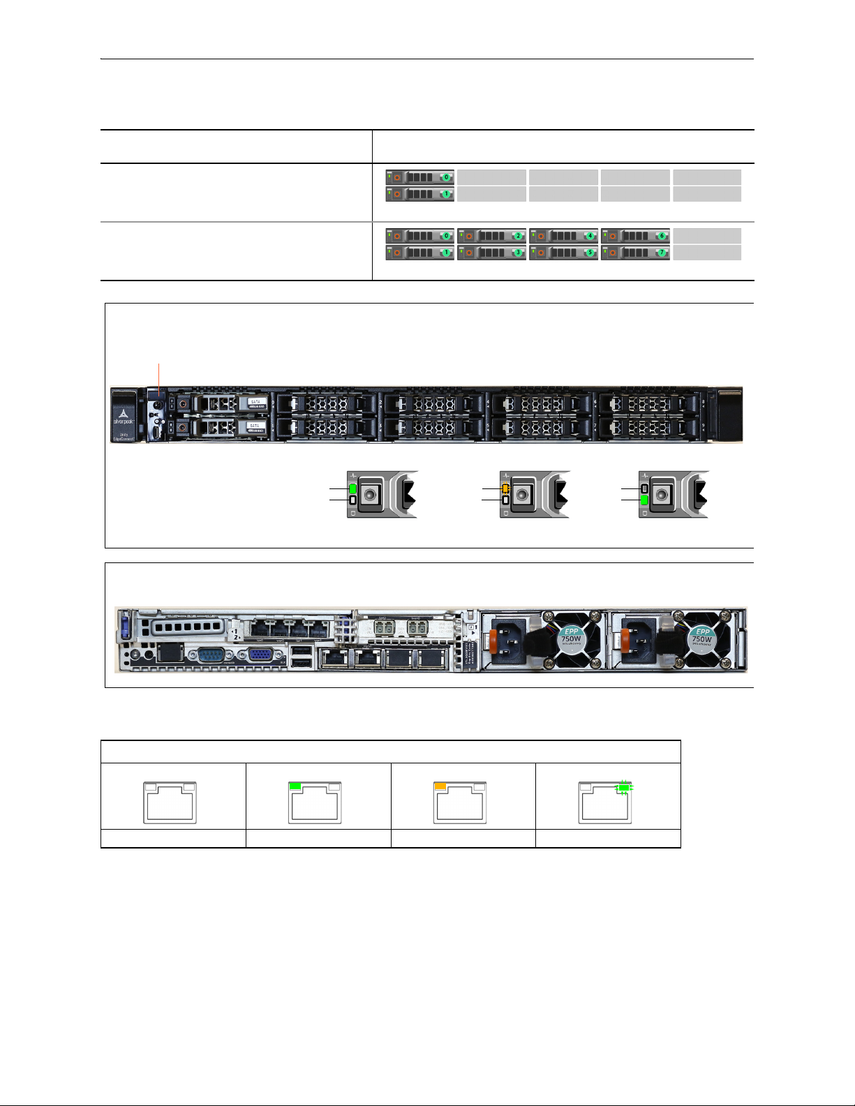
EC-L [PN 200883] Chapter 6 Appliance Views
Front View
Power LED [green = ON]
Status
Activity
Drive online
Status
Activity
Drive failed
Status
Activity
Traffic
(4 blinks/sec)
Rear View
ActivityLink
ActivityLink
ActivityLink
ActivityLink
EC-L [PN 200883]
EC-L
SSD
Supplies Disk Layout
Quantity (minimum)22
User authorized to replace? yes yes
Hot swappable? yes yes
Quantity (maximum)82
User authorized to replace? yes yes
Hot swappable? yes yes
Power
PN 200972-001 Rev B 53
mgmt0 & mgmt1
Not connected Connected at max speed Connected at lower speed Traffic
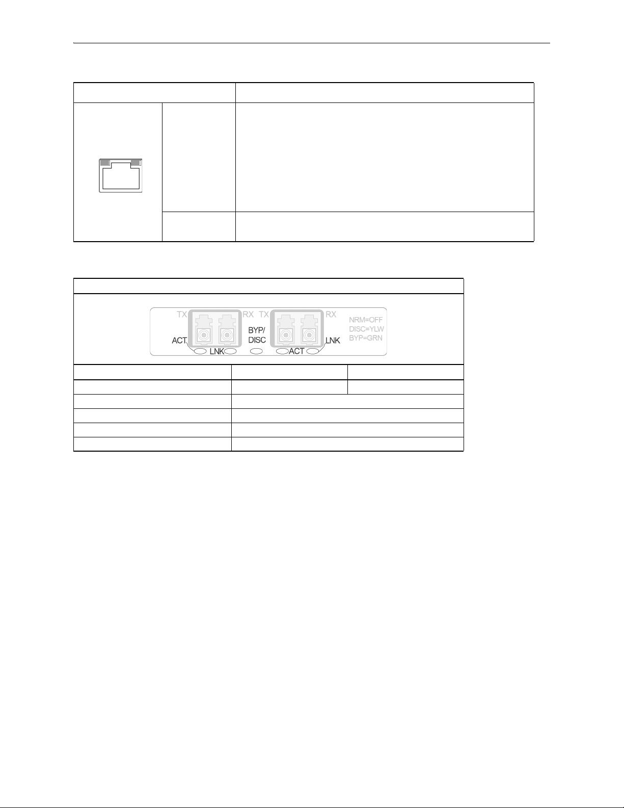
Silver Peak Hardware Reference Guide EC-L [PN 200883]
Link/
Activity
Speed /
Bypass /
Disconnect
lan0 / wan0 / lan1 / wan1
Rear LEDs
LED
Speed / Bypass /
Disconnect
SPEED
• Yello w solid = Connection speed is 1000 Mbps
• Green solid = Connection speed is 100 Mbps
• Not illuminated = Connection speed is 10 Mbps
Bypass/Disconnect
• Green blinking = Bypass
• Yello w blinking = Disconnect
SSD NVMe
Link/ACT • Green solid= Port is active
• Green blinking = There is traffic
1/10 Gbps fiber interfaces for tlan / twan
a
Indicator 10G 1G
LNK Link blue solid green solid
ACT Activity green blinking
BYPASS Bypass green solid
DISC Disconnect yellow solid
NRM Normal off — In NRM mode, the ports are independent interfaces
a. These are SR (Short Reach) modules.
54 PN 200972-001 Rev B

EC-L-NM [PN 200887] Chapter 6 Appliance Views
Front View
Power LED [green = ON]
Status
Activity
Drive online
Status
Activity
Drive failed
Status
Activity
Traffic
(4 blinks/sec)
Rear View
ActivityLink
ActivityLink
ActivityLink
ActivityLink
Link/
Activity
Speed /
Bypass /
Disconnect
EC-L-NM [PN 200887]
EC-L-NM
SSD
Supplies Disk Layout
Quantity 8 2
User authorized to replace? yes yes
Hot swappable? yes yes
Power
PN 200972-001 Rev B 55
mgmt0 & mgmt1
Not connected Connected at max speed Connected at lower speed Traffic
lan0 / wan0 / lan1 / wan1
Rear LEDs
LED
SPEED
Speed / Bypass /
Disconnect
Link/ACT • Green solid= Port is active
• Yello w solid = Connection speed is 1000 Mbps
• Green solid = Connection speed is 100 Mbps
• Not illuminated = Connection speed is 10 Mbps
Bypass/Disconnect
• Green blinking = Bypass
• Yello w blinking = Disconnect
• Green blinking = There is traffic

Silver Peak Hardware Reference Guide EC-L-NM [PN 200887]
1/10 Gbps fiber interfaces for tlan / twan
SSD NVMe
a
Indicator 10G 1G
LNK Link blue solid green solid
ACT Activity green blinking
BYPASS Bypass green solid
DISC Disconnect yellow solid
NRM Normal off — In NRM mode, the ports are independent interfaces
a. These are SR (Short Reach) modules.
56 PN 200972-001 Rev B

EC-XL [PN 200884] Chapter 6 Appliance Views
Front View
Power LED [green = ON]
Status
Activity
Drive online
Status
Activity
Drive failed
Status
Activity
Traffic
(4 blinks/sec)
Front View - with additional optional disks
Status
Activity
Drive online
Status
Activity
Drive failed
Status
Activity
Traffic
(4 blinks/sec)
Status
Activity
Drive online
Status
Activity
Drive failed
Status
Activity
Traffic
(4 blinks/sec)
Status
Activity
Idle
(flashing)
SSD
NVMe
EC-XL [PN 200884]
EC-XL
Drives
Supplies Disk Layout
Quantity (minimum) 2 SSD 2
User authorized to replace? yes yes
Hot swappable? yes yes
Power
Quantity (maximum)2 SSD +
2
4 NVMe
User authorized to replace? yes yes
Hot swappable? yes yes
PN 200972-001 Rev B 57
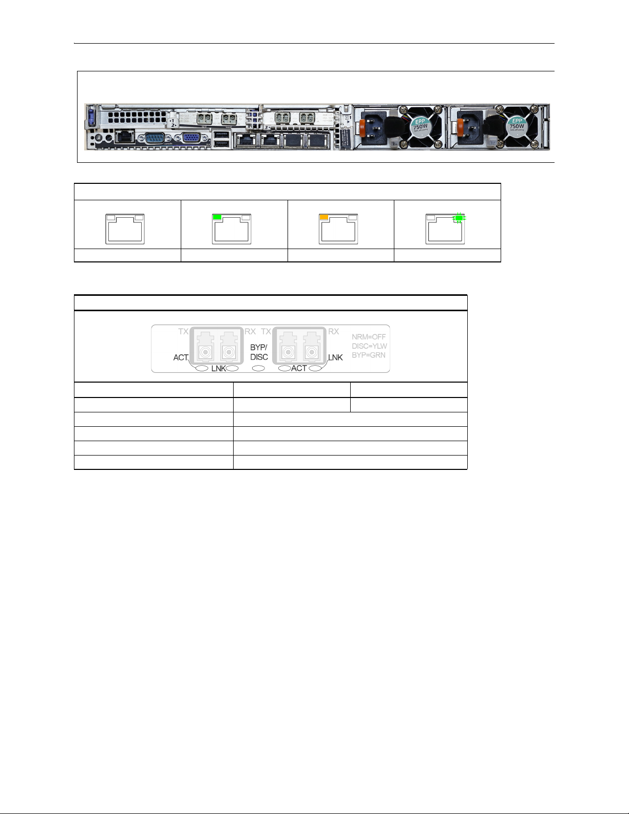
Silver Peak Hardware Reference Guide EC-XL [PN 200884]
Rear View
ActivityLink
ActivityLink
ActivityLink
ActivityLink
mgmt0 & mgmt1
Not connected Connected at max speed Connected at lower speed Traffic
1/10 Gbps fiber interfaces for tlan / twan
a
Indicator 10G 1G
LNK Link blue solid green solid
ACT Activity green blinking
BYPASS Bypass green solid
DISC Disconnect yellow solid
NRM Normal off — In NRM mode, the ports are independent interfaces
a. These are SR (Short Reach) modules.
58 PN 200972-001 Rev B

EC-XL-NM [PN 200888] Chapter 6 Appliance Views
Front View
Power LED [green = ON]
Status
Activity
Drive online
Status
Activity
Drive failed
Status
Activity
Traffic
(4 blinks/sec)
Status
Activity
Drive online
Status
Activity
Drive failed
Status
Activity
Traffic
(4 blinks/sec)
Status
Activity
Idle
(flashing)
SSD
NVMe
Rear View
ActivityLink
ActivityLink
ActivityLink
ActivityLink
EC-XL-NM [PN 200888]
EC-XL-NM
Quantity 2 SSD +
Drives
Supplies Disk Layout
2
4 NVMe
User authorized to replace? yes yes
Hot swappable? yes yes
Power
mgmt0 & mgmt1
Not connected Connected at max speed Connected at lower speed Traffic
PN 200972-001 Rev B 59

Silver Peak Hardware Reference Guide EC-XL-NM [PN 200888]
1/10 Gbps fiber interfaces for tlan / twan
a
Indicator 10G 1G
LNK Link blue solid green solid
ACT Activity green blinking
BYPASS Bypass green solid
DISC Disconnect yellow solid
NRM Normal off — In NRM mode, the ports are independent interfaces
a. These are SR (Short Reach) modules.
60 PN 200972-001 Rev B

NX-700 [PN 200849] Chapter 6 Appliance Views
NX-700 — Front View
NX-700 — Rear View
Link/
Activity
Speed
NX-700 [PN 200849]
NX-700 SSD Power Adapter
Quantity 1 1
User authorized to replace? no N/A
Hot swappable? -- --
NX-700
Front LEDs
LED
Power • Illuminated = System is powered on
• Not illuminated = System is powered off
Status • Green = Operational state is normal
• Red = System is malfunctioning
SSD • Blinking = Data access activities
Rear LEDs
PN 200972-001 Rev B 61
Speed • Amber = Connection speed is 1000 Mbps
• Green = Connection speed is 100 Mbps
• Not illuminated = Connection speed is 10 Mbps
Link/ACT • Amber solid= Port is active
• Amber blinking = There is traffic
Both LEDs • Not illuminated = BYPASS

Silver Peak Hardware Reference Guide NX-1700 AC [PN 200404 and PN 200576]
Power LED
Power switch
When you toggle the Power switch, verify
that the Power LED illuminates green.
NX-1700 (AC) — Front View
parallel port
console
[serial port]
VGA port
auxiliary
port
management interfaces
[mgmt0 / mgmt1]
network interfaces
[lan0 / wan0 / lan1 / wan1]
NX-1700
power supply LED
NX-1700 (AC) — Rear View
NX-1700 AC [PN 200404 and PN 200576]
NX-1700 HDD Power Supplies
Quantity 1 1
User authorized to replace? no no
Hot swappable? -- --
There are a couple of different physical chassis for AC current. The functional distinction is only in
whether the physical interfaces are on the front panel or the rear panel.
Option #1 – NX-1700 AC with Interfaces on Rear Panel [PN 200404]
62 PN 200972-001 Rev B

NX-1700 AC [PN 200404 and PN 200576] Chapter 6 Appliance Views
Power LED
console
[serial port]
auxiliary
port
management interfaces
[mgmt0 / mgmt1]
network interfaces
[lan0 / wan0 / lan1 / wan1]
NX-1700
NX-1700 (AC) — Front View
Power switch
Power plug
NX-1700 (AC) — Rear View
Link/
Activity
Speed
Link/
Activity
Speed
Link/
Activity
Speed
Link/
Activity
Speed
Link/
Activity
Speed
Option #2 – NX-1700 AC with Interfaces on Front Panel [PN 200576]
NX-1700
Link/Activity:
blinking = traffic
--
Speed = solid
PN 200972-001 Rev B 63
Not
connected
mgmt0 & mgmt1 lan0 / wan0 /
10 Mbps 100 Mbps 1000 Mbps
lan1 / wan1

Silver Peak Hardware Reference Guide NX-1700 [PN 200863]
NX-1700 — Front View
NX-1700— Rear View
Link/
Activity
Speed
NX-1700 [PN 200863]
NX-1700 SSD Power Adapter
Quantity 1 1
User authorized to replace? no N/A
Hot swappable? -- --
NX-1700
Front LEDs
LED
Power • Illuminated = System is powered on
• Not illuminated = System is powered off
Status • Green = Operational state is normal
• Red = System is malfunctioning
SSD • Blinking = Data access activities
Rear LEDs
64 PN 200972-001 Rev B
Speed • Amber = Connection speed is 1000 Mbps
• Green = Connection speed is 100 Mbps
• Not illuminated = Connection speed is 10 Mbps
Link/ACT • Amber solid= Port is active
• Amber blinking = There is traffic
Both LEDs • Not illuminated = BYPASS

NX-1700 DC [PN 200464] Chapter 6 Appliance Views
Power LED
Power switch
When you toggle the Power switch, verify
that the Power LED illuminates green.
NX-1700 (DC) — Front View
parallel port
console
[serial port]
VGA port
auxiliary
port
management interfaces
[mgmt0 / mgmt1]
network interfaces
[lan0 / wan0 / lan1 / wan1]
power supply LED
DC terminal connector (DC)
side view
NX-1700 (DC) — Rear View
a Connect one wire from the NX-1700’s 0V terminal to
the DC source
0V terminal.
b Connect the second wire from the NX-1700’s
–48V
terminal to the DC source
–48V terminal.
Link/
Activity
Speed
Link/
Activity
Speed
Link/
Activity
Speed
Link/
Activity
Speed
Link/
Activity
Speed
NX-1700 DC [PN 200464]
NX-1700 DC HDD Power Supplies
Quantity 1 1
User authorized to replace? no no
Hot swappable? -- --
NX-1700
Link/Activity:
blinking = traffic
--
Speed = solid
PN 200972-001 Rev B 65
mgmt0 & mgmt1 lan0 / wan0 /
Not
connected
10 Mbps 100 Mbps 1000 Mbps
lan1 / wan1

Silver Peak Hardware Reference Guide NX-2600 [PN 200178] / NX-2610 [PN 200193]
Power LED [blue]
Power switch
On the front panel, verify that the
Power LED illuminates blue.
NX-2600 and NX-2610 — Front Views
Not usedAlarm MuteSystem Reset
mgmt0 mgmt1
Disk Drive Drive
activity
NX-2600 — Disk Layout
User replacement NOT authorized
NX-2610
NX-2600 — Rear View
NX-2610
Link/
Activity Speed
Link/
Activity Speed
Link/
Activity Speed
Link/
Activity Speed
Link/
Activity Speed
NX-2600 [PN 200178] / NX-2610 [PN 200193]
NX-2600
NX-2610
Speed = solid
--
Link/Activity:
blinking = traffic
66 PN 200972-001 Rev B
mgmt0 & mgmt1
Not connected 10 Mbps 100 Mbps 1000 Mbps Auto

NX-2700 [PN 200401] Chapter 6 Appliance Views
Power button
[plugging the power cords
in automatically powers
up the appliance]
Power LED [blue = ON]
System reset
Alarm mute
Illuminates red when a power
supply is disconnected or off
NX-2700 — Front View
NX-2700 — Disk Layout
NX-2700 [PN 200401]
NX-2700 HDD Power Supplies
Quantity 2 2
User authorized to replace? yes yes
Hot swappable? yes yes
PN 200972-001 Rev B 67

Silver Peak Hardware Reference Guide NX-2700 [PN 200401]
Each power cord socket has a corresponding green LED to its
left. When a socket receives power, its LED illuminates green.
NX-2700 — Rear View
Link/
Activity
Speed
Link/
Activity
Speed
Link/
Activity
Speed
Link/
Activity
Speed
Link/Activity
lan0 wan0 lan1 wan1
Link/ActivityLink/Activity Link/Activity
lan0 wan0 lan1 wan1
lan0 wan0 lan1 wan1
NX-2700
Speed = solid
Link/Activity:
solid = link
blinking = traffic
NX-2700
Link/Activity:
solid green = link good
blinking green = traffic
system bypass mode
Ports 0 + 2 – solid green
Ports 1 + 3 – OFF
slave ports
not in system bypass
Ports 0 + 2 – OFF
Ports 1 + 3 – solid green
mgmt0 & mgmt1
Not connected 10 Mbps 100 Mbps 1000 Mbps
Network interfaces
68 PN 200972-001 Rev B
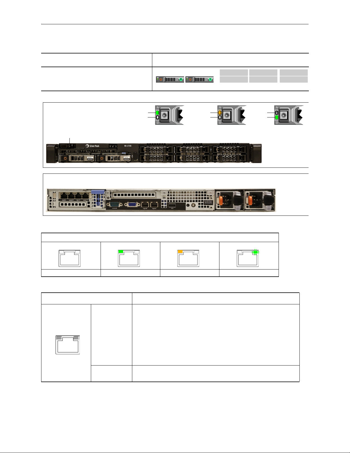
NX-2700 [PN 200697] Chapter 6 Appliance Views
Front View
Power LED [blue = ON]
Status
Activity
Drive online
Status
Activity
Drive failed
Status
Activity
Traffic
(4 blinks/sec)
Rear View
ActivityLink
ActivityLink
ActivityLink
ActivityLink
Link/
Activity
Speed /
Bypass /
Disconnect
NX-2700 [PN 200697]
NX-2700
SSD
Supplies Disk Layout
Quantity 2 2
User authorized to replace? yes yes
Hot swappable? yes yes
Power
mgmt0 & mgmt1
Not connected Connected at max speed Connected at lower speed Traffic
lan0 / wan0 / lan1 / wan1
Rear LEDs
LED
SPEED
Speed / Bypass /
Disconnect
Link/ACT • Green solid= Port is active
• Yello w solid = Connection speed is 1000 Mbps
• Green solid = Connection speed is 100 Mbps
• Not illuminated = Connection speed is 10 Mbps
Bypass/Disconnect
• Green blinking = Bypass
• Yello w blinking = Disconnect
• Green blinking = There is traffic
PN 200972-001 Rev B 69
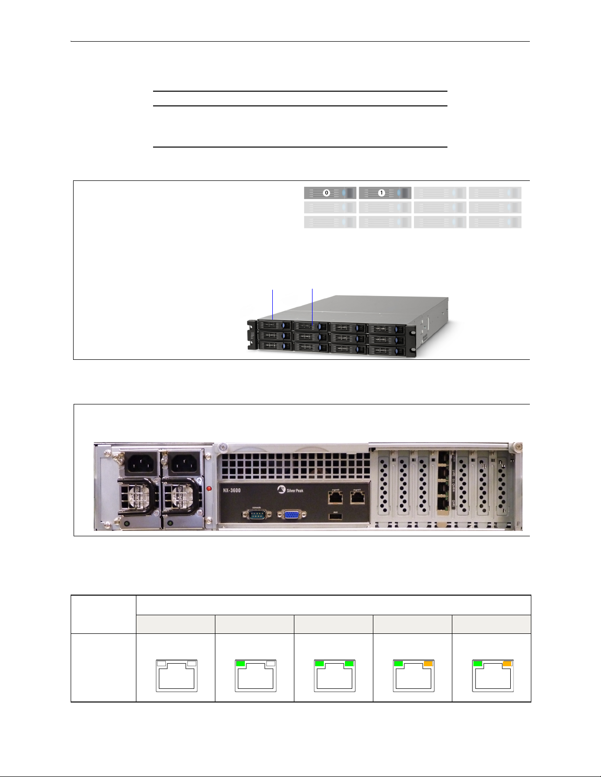
Silver Peak Hardware Reference Guide NX-3600 [PN 200348]
Disk 0 Disk 1
These two slots house the Disk
Drives you can remove and replace.
NX-3600 — Front View & Disk Layout
NX-3600 — Rear View
Link/
Activity Speed
Link/
Activity Speed
Link/
Activity Speed
Link/
Activity Speed
Link/
Activity Speed
NX-3600 [PN 200348]
NX-3600 HDD Power Supplies
Quantity 2 2
User authorized to replace? yes yes
Hot swappable? no yes
.
NX-3600
Not connected 10 Mbps 100 Mbps 1000 Mbps Auto
Speed = solid
--
Link/Activity:
blinking = traffic
70 PN 200972-001 Rev B
mgmt0 & mgmt1

NX-3700 [PN 200400] Chapter 6 Appliance Views
Power button
[plugging the power cords
in automatically powers
up the appliance]
Power LED [blue = ON]
System reset
Alarm mute
Illuminates red when a power
supply is disconnected or off
NX-3700 — Front View
NX-3700 — Disk Layout
NX-3700 [PN 200400]
NX-3700 HDD Power Supplies
Quantity 2 2
User authorized to replace? yes yes
Hot swappable? yes yes
PN 200972-001 Rev B 71

Silver Peak Hardware Reference Guide NX-3700 [PN 200400]
Each power cord socket has a corresponding green LED to its
left. When a socket receives power, its LED illuminates green.
NX-3700 — Rear View
Link/
Activity
Speed
Link/
Activity
Speed
Link/
Activity
Speed
Link/
Activity
Speed
Link/Activity
lan0 wan0 lan1 wan1
Link/ActivityLink/Activity Link/Activity
lan0 wan0 lan1 wan1
lan0 wan0 lan1 wan1
.
NX-3700
Speed = solid
Link/Activity:
solid = link
blinking = traffic
NX-3700
Link/Activity:
solid green = link good
blinking green = traffic
system bypass mode
Ports 0 + 2 – solid green
Ports 1 + 3 – OFF
slave ports
not in system bypass
Ports 0 + 2 – OFF
Ports 1 + 3 – solid green
mgmt0 & mgmt1
Not connected 10 Mbps 100 Mbps 1000 Mbps
Network interfaces
72 PN 200972-001 Rev B

NX-3700 [PN 200698] Chapter 6 Appliance Views
Front View
Power LED [blue = ON]
Status
Activity
Drive online
Status
Activity
Drive failed
Status
Activity
Traffic
(4 blinks/sec)
Rear View
ActivityLink
ActivityLink
ActivityLink
ActivityLink
Link/
Activity
Speed /
Bypass /
Disconnect
NX-3700 [PN 200698]
NX-3700
HDD
Supplies Disk Layout
Quantity 2 2
User authorized to replace? yes yes
Hot swappable? yes yes
Power
.
mgmt0 & mgmt1
Not connected Connected at max speed Connected at lower speed Traffic
lan0 / wan0 / lan1 / wan1
Rear LEDs
LED
SPEED
Speed / Bypass /
Disconnect
Link/ACT • Green solid= Port is active
• Yello w solid = Connection speed is 1000 Mbps
• Green solid = Connection speed is 100 Mbps
• Not illuminated = Connection speed is 10 Mbps
Bypass/Disconnect
• Green blinking = Bypass
• Yello w blinking = Disconnect
• Green blinking = There is traffic
PN 200972-001 Rev B 73

Silver Peak Hardware Reference Guide NX-5600 [PN 200231]
Power LED [blue = ON]
NX-5600 — Front Views
Not usedAlarm MuteSystem Reset
mgmt0 mgmt1
Disk Drive activity
[Yellow = busy]
NX-5600 — Front Views
NX-5600 — Rear View
NX-5600 [PN 200231]
NX-5600 HDD Power Supplies
Quantity 8 3
User authorized to replace? yes yes
Hot swappable? yes yes
74 PN 200972-001 Rev B

NX-5600 [PN 200231] Chapter 6 Appliance Views
Link/
Activity Speed
Link/
Activity Speed
Link/
Activity Speed
Link/
Activity Speed
Link/
Activity Speed
mgmt0 & mgmt1
NX-5600
Speed = solid
--
Link/Activity:
blinking = traffic
Not
connected
10 Mbps 100 Mbps 1000 Mbps Auto
PN 200972-001 Rev B 75

Silver Peak Hardware Reference Guide NX-5700 [PN 200399]
Power button
[plugging the power cords
in automatically powers
up the appliance]
Power LED [blue = ON]
System reset
Alarm mute
Illuminates red when a power
supply is disconnected or off
NX-5700 — Front View
NX-5700 — Disk Layout
NX-5700 [PN 200399]
NX-5700 HDD Power Supplies
Quantity 8 2
User authorized to replace? yes yes
Hot swappable? yes yes
76 PN 200972-001 Rev B

NX-5700 [PN 200399] Chapter 6 Appliance Views
Each power cord socket has a corresponding green LED to its
left. When a socket receives power, its LED illuminates green.
NX-5700 — Rear View
Link/
Activity
Speed
Link/
Activity
Speed
Link/
Activity
Speed
Link/
Activity
Speed
Link/Activity
lan0 wan0 lan1 wan1
Link/ActivityLink/Activity Link/Activity
lan0 wan0 lan1 wan1
lan0 wan0 lan1 wan1
.
NX-5700
Speed = solid
Link/Activity:
solid = link
blinking = traffic
NX-5700
Link/Activity:
solid green = link good
blinking green = traffic
system bypass mode
Ports 0 + 2 – solid green
Ports 1 + 3 – OFF
slave ports
not in system bypass
Ports 0 + 2 – OFF
Ports 1 + 3 – solid green
mgmt0 & mgmt1
Not connected 10 Mbps 100 Mbps 1000 Mbps
Network interfaces
PN 200972-001 Rev B 77

Silver Peak Hardware Reference Guide NX-5700 [PN 200699]
Front View
Power LED [blue = ON]
Status
Activity
Drive online
Status
Activity
Drive failed
Status
Activity
Traffic
(4 blinks/sec)
Rear View
ActivityLink
ActivityLink
ActivityLink
ActivityLink
Link/
Activity
Speed /
Bypass /
Disconnect
NX-5700 [PN 200699]
NX-5700
SSD
Supplies Disk Layout
Quantity 8 2
User authorized to replace? yes yes
Hot swappable? yes yes
Power
.
mgmt0 & mgmt1
Not connected Connected at max speed Connected at lower speed Traffic
lan0 / wan0 / lan1 / wan1
Rear LEDs
LED
SPEED
Speed / Bypass /
Disconnect
Link/ACT • Green solid= Port is active
• Yello w solid = Connection speed is 1000 Mbps
• Green solid = Connection speed is 100 Mbps
• Not illuminated = Connection speed is 10 Mbps
Bypass/Disconnect
• Green blinking = Bypass
• Yello w blinking = Disconnect
• Green blinking = There is traffic
78 PN 200972-001 Rev B

NX-6700 [PN 200828] Chapter 6 Appliance Views
Front View
Status
Activity
Drive online
Status
Activity
Drive failed
Status
Activity
Traffic
(4 blinks/sec)
Power LED [blue = ON]
Rear View
ActivityLink
ActivityLink
ActivityLink
ActivityLink
Link/
Activity
Speed /
Bypass /
Disconnect
NX-6700 [PN 200828]
NX-6700
SSD
Supplies Disk Layout
Quantity 8 2
User authorized to replace? yes yes
Hot swappable? yes yes
Power
.
mgmt0 & mgmt1
Not connected Connected at max speed Connected at lower speed Traffic
lan0 / wan0 / lan1 / wan1
Rear LEDs
LED
SPEED
Speed / Bypass /
Disconnect
Link/ACT • Green solid= Port is active
• Yello w solid = Connection speed is 1000 Mbps
• Green solid = Connection speed is 100 Mbps
• Not illuminated = Connection speed is 10 Mbps
Bypass/Disconnect
• Green blinking = Bypass
• Yello w blinking = Disconnect
• Green blinking = There is traffic
PN 200972-001 Rev B 79
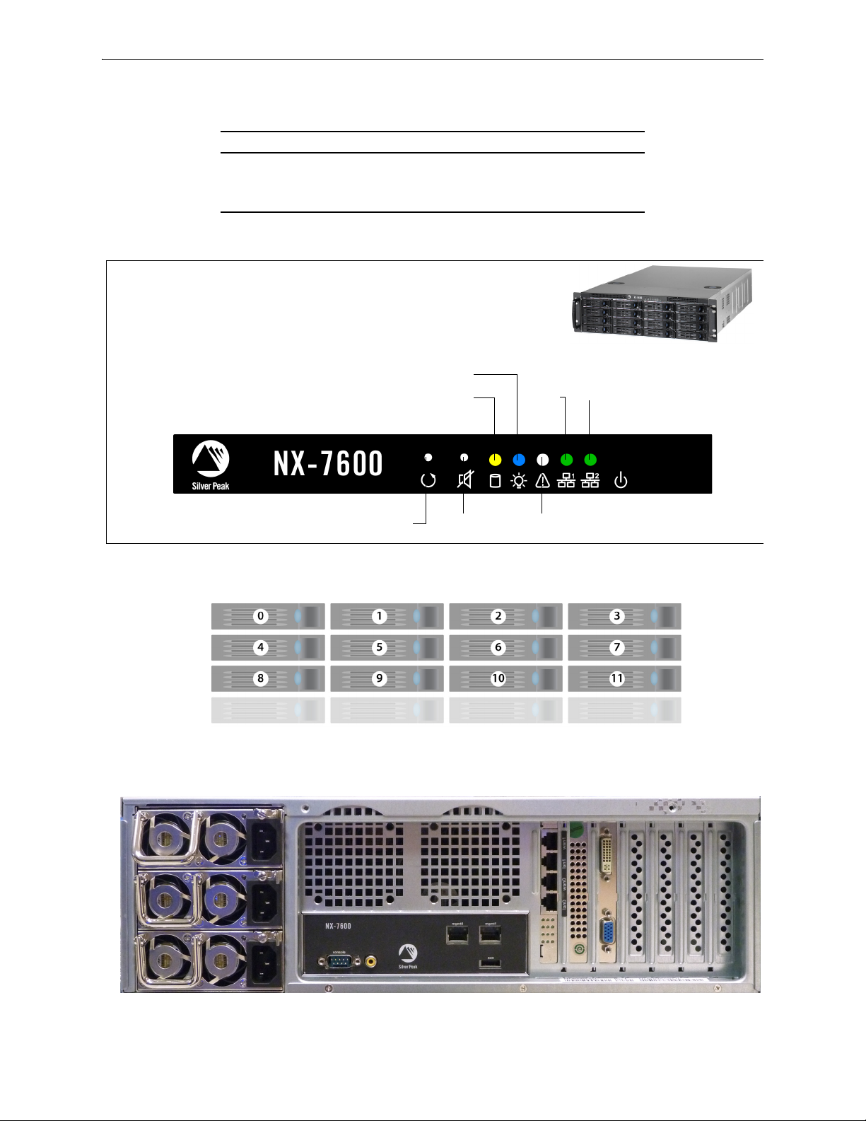
Silver Peak Hardware Reference Guide NX-7600 [PN 200225]
Power LED [blue = ON]
NX-7600 — Front Views
Not usedAlarm MuteSystem Reset
mgmt0 mgmt1
Disk Drive activity
[Yellow = busy]
NX-7600 — Disk Layout
NX-7600 — Rear View
NX-7600 [PN 200225]
NX-7600 HDD Power Supplies
Quantity 12 3
User authorized to replace? yes yes
Hot swappable? yes yes
80 PN 200972-001 Rev B

NX-7600 [PN 200225] Chapter 6 Appliance Views
Link/
Activity Speed
Link/
Activity Speed
Link/
Activity Speed
Link/
Activity Speed
Link/
Activity Speed
mgmt0 & mgmt1
NX-7600
Speed = solid
--
Link/Activity:
blinking = traffic
Not
connected
10 Mbps 100 Mbps 1000 Mbps Auto
PN 200972-001 Rev B 81

Silver Peak Hardware Reference Guide NX-7700 [PN 200398]
Power button
[plugging the power cords
in automatically powers
up the appliance]
Power LED [blue = ON]
System reset
Alarm mute
Illuminates red when a power
supply is disconnected or off
NX-7700 — Front View
NX-7700 — Disk Layout
NX-7700 [PN 200398]
NX-7700 HDD Power Supplies
Quantity 10 2
User authorized to replace? yes yes
Hot swappable? yes yes
82 PN 200972-001 Rev B

NX-7700 [PN 200398] Chapter 6 Appliance Views
Each power cord socket has a corresponding green LED to its
left. When a socket receives power, its LED illuminates green.
NX-7700 — Rear View
Link/
Activity
Speed
Link/
Activity
Speed
Link/
Activity
Speed
Link/
Activity
Speed
Link/Activity
lan0 wan0 lan1 wan1
Link/ActivityLink/Activity Link/Activity
lan0 wan0 lan1 wan1
lan0 wan0 lan1 wan1
.
NX-7700
Speed = solid
Link/Activity:
solid = link
blinking = traffic
NX-7700
Link/Activity:
solid green = link good
blinking green = traffic
system bypass mode
Ports 0 + 2 – solid green
Ports 1 + 3 – OFF
slave ports
not in system bypass
Ports 0 + 2 – OFF
Ports 1 + 3 – solid green
mgmt0 & mgmt1
Not connected 10 Mbps 100 Mbps 1000 Mbps
Network interfaces
PN 200972-001 Rev B 83

Silver Peak Hardware Reference Guide NX-7700 [PN 200702]
Front View
Power LED [blue = ON]
Status
Activity
Drive online
Status
Activity
Drive failed
Status
Activity
Traffic
(4 blinks/sec)
Rear View
ActivityLink
ActivityLink
ActivityLink
ActivityLink
Link/
Activity
Speed /
Bypass /
Disconnect
NX-7700 [PN 200702]
NX-7700
SSD
Supplies Disk Layout
Quantity 8 2
User authorized to replace? yes yes
Hot swappable? yes yes
Power
.
mgmt0 & mgmt1
Not connected Connected at max speed Connected at lower speed Traffic
lan0 / wan0 / lan1 / wan1
Rear LEDs
LED
SPEED
Speed / Bypass /
Disconnect
Link/ACT • Green solid= Port is active
• Yello w solid = Connection speed is 1000 Mbps
• Green solid = Connection speed is 100 Mbps
• Not illuminated = Connection speed is 10 Mbps
Bypass/Disconnect
• Green blinking = Bypass
• Yello w blinking = Disconnect
• Green blinking = There is traffic
84 PN 200972-001 Rev B

NX-8600 [PN 200181] Chapter 6 Appliance Views
Power LED [blue = ON]
NX-8600 — Front View
Not usedAlarm MuteSystem Reset
mgmt0 mgmt1
Disk Drive Drive activity
[Yellow = busy]
NX-8600 — Disk Layout
NX-8600 — Rear View
NX-8600 [PN 200181]
NX-8600 HDD Power Supplies
Quantity 16 3
User authorized to replace? yes yes
Hot swappable? yes yes
PN 200972-001 Rev B 85
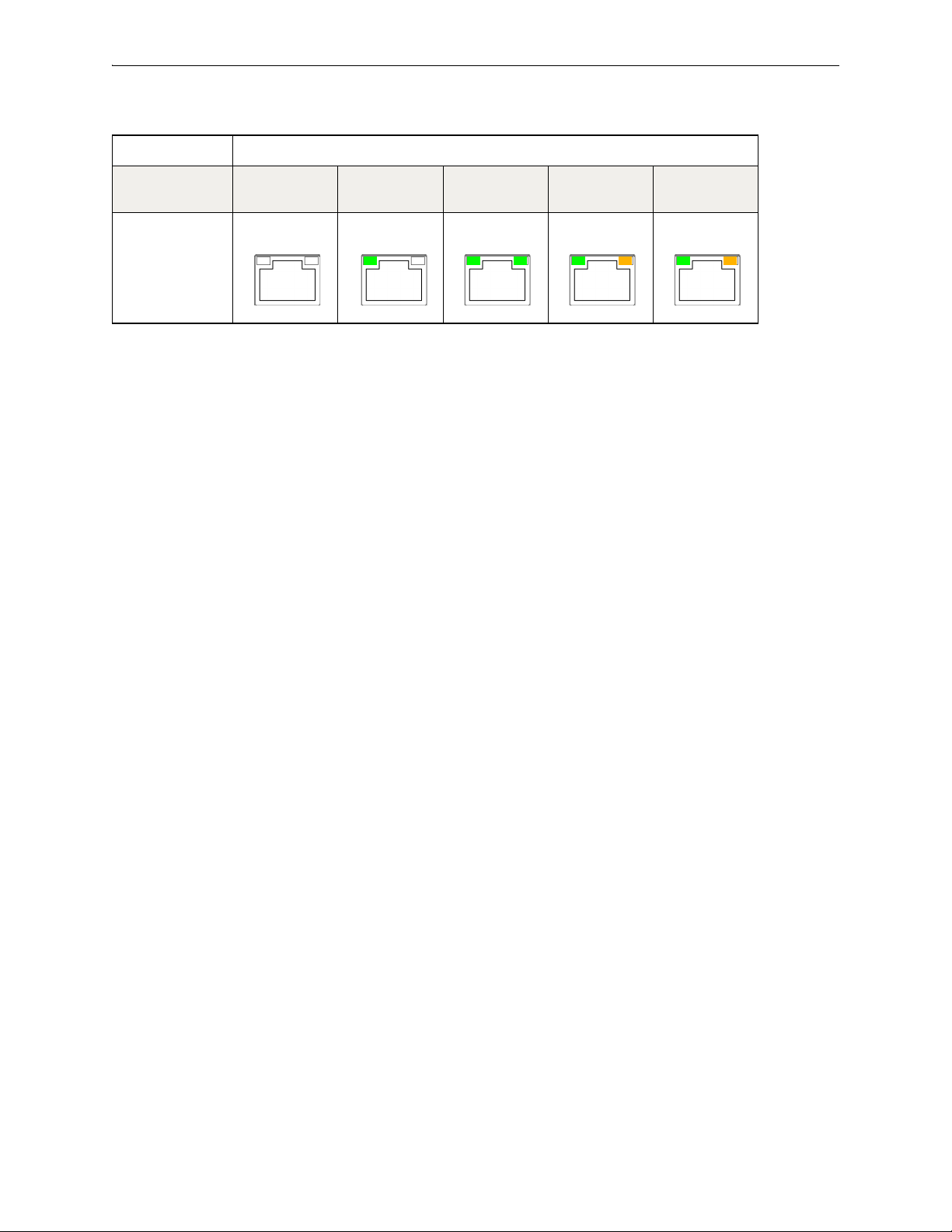
Silver Peak Hardware Reference Guide NX-8600 [PN 200181]
Link/
Activity Speed
Link/
Activity Speed
Link/
Activity Speed
Link/
Activity Speed
Link/
Activity Speed
mgmt0 & mgmt1
NX-8600
Speed = solid
--
Link/Activity:
blinking = traffic
Not
connected
10 Mbps 100 Mbps 1000 Mbps Auto
86 PN 200972-001 Rev B

NX-8700 [PN 200397] Chapter 6 Appliance Views
NX-8700 — Front View
Power supply warning LED
[
red = 1 PS down or missing]
Alarm mute
Power LED [blue = on]
System reset
Power switch
blue = disk on
NO LIGHT = OFF
DISK LEDs:
green = disk activity
red = error [no access to drive]
Solid-state disks
SATA hard
disk drives
SATA hard
disk drives
Note that the NX-9700 and NX-8700 appliances contain a mix
of SATA hard disk drives and SSDs (solid-state drives).
NX-8700 — Disk Layout
The two NX-8700s differ only in the placement of the solid state drives.
NX-8700 [PN 200397]
NX-8700 Drives Power Supplies
Quantity 14 2
User authorized to replace? yes yes
Hot swappable? yes yes
PN 200972-001 Rev B 87

Silver Peak Hardware Reference Guide NX-8700 [PN 200397]
SATA hard
diskdrives
SATA hard
disk drives
Note that the NX-9700 and NX-8700 appliances contain a mix
of SATA hard disk drives and SSDs (solid-state drives).
Solid-state disks
NX-8700v — Disk Layout
auxiliary port
console [serial port]
VGA port
Power Supply LEDs
green = power on
management
interfaces
copper
network interfaces
10 Gbps fiber
network interfaces
NX-8700 — Rear View
Link/
Activity
Speed
Link/
Activity
Speed
Link/
Activity
Speed
Link/
Activity
Speed
88 PN 200972-001 Rev B
Management interfaces
NX-8700
Speed = solid
Link/Activity:
solid = link
blinking = traffic
mgmt0 & mgmt1
Not connected 10 Mbps 100 Mbps 1000 Mbps

NX-8700 [PN 200397] Chapter 6 Appliance Views
Link/Activity
lan0 wan0 lan1 wan1
Link/ActivityLink/Activity Link/Activity
lan0 wan0 lan1 wan1
lan0 wan0 lan1 wan1
Network interfaces
NX-8700
Link/Activity:
solid green = link good
blinking green = traffic
system bypass mode
Ports 0 + 2 – solid green
Ports 1 + 3 – OFF
slave ports
not in system bypass
Ports 0 + 2 – OFF
Ports 1 + 3 – solid green
10 Gbps fiber interfaces
NX-8700
all LEDs are green
Link = solid
Activity = blinking
Network interfaces
tlan0 / twan0
You have the option to separately order LR (Long Reach) 10 Gbps Fiber Interfaces to replace the default
SR (Short Reach) modules in the NX-8700 appliance.
Silver Peak supports different module combinations. For example, you may have an SR (Short
Reach) interface for the LAN side and an LR (or Long Reach) for the WAN.
These modules are hot-swappable.
You can distinguish the SR module from the LR module by the number on the label and the color of the
handle.
PN 200972-001 Rev B 89

Silver Peak Hardware Reference Guide NX-8700 [PN 200397]
FTLX8571D3BCL — SR — Short Reach
• Bail (handle) is beige
• Default shipping module
FTLX1471D3BCL — LR — Long Reach
• Bail (handle) is blue
• Optional, separate purchase
90 PN 200972-001 Rev B

NX-8700 [PN 200767] Chapter 6 Appliance Views
Front View
Power LED [blue = ON]
Status
Activity
Drive online
Status
Activity
Drive failed
Status
Activity
Traffic
(4 blinks/sec)
Rear View
ActivityLink
ActivityLink
ActivityLink
ActivityLink
Link/
Activity
Speed /
Bypass /
Disconnect
NX-8700 [PN 200767]
NX-8700
SSD
Supplies Disk Layout
Quantity 14 2
User authorized to replace? yes yes
Hot swappable? yes yes
Power
PN 200972-001 Rev B 91
.
mgmt0 & mgmt1
Not connected Connected at max speed Connected at lower speed Traffic
lan0 / lan1 / wan0 / wan1
Rear LEDs
LED
SPEED
Speed / Bypass /
Disconnect
Link/ACT • Green solid= Port is active
• Yello w solid = Connection speed is 1000 Mbps
• Green solid = Connection speed is 100 Mbps
• Not illuminated = Connection speed is 10 Mbps
Bypass/Disconnect
• Green blinking = Bypass
• Yello w blinking = Disconnect
• Green blinking = There is traffic

Silver Peak Hardware Reference Guide NX-8700 [PN 200767]
10 Gbps fiber interfaces
NX-8700
all LEDs are green
Link = solid
Activity = blinking
tlan0 / twan0
You have the option to separately order LR (Long Reach) 10 Gbps Fiber Interfaces to replace the default
SR (Short Reach) modules in the NX-8700 appliance.
Silver Peak supports different module combinations. For example, you may have an SR (Short
Reach) interface for the LAN side and an LR (or Long Reach) for the WAN.
These modules are hot-swappable.
You can distinguish the SR module from the LR module by the number on the label and the color of the
handle.
FTLX8571D3BCL — SR — Short Reach
• Bail (handle) is beige
• Default shipping module
92 PN 200972-001 Rev B
FTLX1471D3BCL — LR — Long Reach
• Bail (handle) is blue
• Optional, separate purchase

NX-8700 [PN 200879] Chapter 6 Appliance Views
Front View
Power LED [green = ON]
Status
Activity
Drive online
Status
Activity
Drive failed
Status
Activity
Traffic
(4 blinks/sec)
Rear View
ActivityLink
ActivityLink
ActivityLink
ActivityLink
NX-8700 [PN 200879]
NX-8700
SSD
Supplies Disk Layout
Quantity 8 2
User authorized to replace? yes yes
Hot swappable? yes yes
Power
PN 200972-001 Rev B 93
mgmt0 & mgmt1
Not connected Connected at max speed Connected at lower speed Traffic

Silver Peak Hardware Reference Guide NX-8700 [PN 200879]
Link/
Activity
Speed /
Bypass /
Disconnect
lan0 / lan1 / wan0 / wan1
Rear LEDs
LED
Speed / Bypass /
Disconnect
SPEED
• Yello w solid = Connection speed is 1000 Mbps
• Green solid = Connection speed is 100 Mbps
• Not illuminated = Connection speed is 10 Mbps
Bypass/Disconnect
• Green blinking = Bypass
• Yello w blinking = Disconnect
Link/ACT • Green solid= Port is active
• Green blinking = There is traffic
1/10 Gbps fiber interfaces for tlan / twan
a
Indicator 10G 1G
LNK Link blue solid green solid
ACT Activity green blinking
BYPASS Bypass green solid
DISC Disconnect yellow solid
NRM Normal off — In NRM mode, the ports are independent interfaces
a. These are SR (Short Reach) modules.
94 PN 200972-001 Rev B
 Loading...