


Silver Peak
Hardware Reference Guide
VXOA 7.3.4
December 2015
PN 200972-001 Rev B

Silver Peak Hardware Reference Guide
Silver Peak Hardware Reference Guide
Document PN 200972-001 Rev B
Date: December 2015
Copyright © 2015 Silver Peak Systems, Inc. All rights reserved. Information in this document is subject to change at any time. Use of
this documentation is restricted as specified in the End User License Agreement. No part of this documentation can be reproduced,
except as noted in the End User License Agreement, in whole or in part, without the written consent of Silver Peak Systems, Inc.
Trademark Notification
The following are trademarks of Silver Peak Systems, Inc.: Silver Peak SystemsTM, the Silver Peak logo, Network MemoryTM, Silver
Peak NX-Series
Orchestrator
respective companies or organizations.
TM
, Silver Peak VX-SeriesTM, Silver Peak VRX-SeriesTM, Silver Peak Unity EdgeConnectTM, and Silver Peak
TM
. All trademark rights reserved. All other brand or product names are trademarks or registered trademarks of their
Warranties and Disclaimers
THIS DOCUMENTATION IS PROVIDED “AS IS” WITHOUT WARRANTY OF ANY KIND, EITHER EXPRESSED OR IMPLIED,
INCLUDING, BUT NOT LIMITED TO, THE IMPLIED WARRANTIES OF MERCHANTABILITY, FITNESS FOR A PARTICULAR
PURPOSE, OR NON-INFRINGEMENT. SILVER PEAK SYSTEMS, INC. ASSUMES NO RESPONSIBILITY FOR ERRORS OR
OMISSIONS IN THIS DOCUMENTATION OR OTHER DOCUMENTS WHICH ARE REFERENCED BY OR LINKED TO THIS
DOCUMENTATION. REFERENCES TO CORPORATIONS, THEIR SERVICES AND PRODUCTS, ARE PROVIDED “AS IS”
WITHOUT WARRANTY OF ANY KIND, EITHER EXPRESSED OR IMPLIED. IN NO EVENT SHALL SILVER PEAK SYSTEMS, INC.
BE LIABLE FOR ANY SPECIAL, INCIDENTAL, INDIRECT OR CONSEQUENTIAL DAMAGES OF ANY KIND, OR ANY DAMAGES
WHATSOEVER, INCLUDING, WITHOUT LIMITATION, THOSE RESULTING FROM LOSS OF USE, DATA OR PROFITS,
WHETHER OR NOT ADVISED OF THE POSSIBILITY OF DAMAGE, AND ON ANY THEORY OF LIABILITY, ARISING OUT OF OR
IN CONNECTION WITH THE USE OF THIS DOCUMENTATION. THIS DOCUMENTATION MAY INCLUDE TECHNICAL OR OTHER
INACCURACIES OR TYPOGRAPHICAL ERRORS. CHANGES ARE PERIODICALLY ADDED TO THE INFORMATION HEREIN;
THESE CHANGES WILL BE INCORPORATED IN NEW EDITIONS OF THE DOCUMENTATION. SILVER PEAK SYSTEMS, INC.
MAY MAKE IMPROVEMENTS AND/OR CHANGES IN THE PRODUCT(S) AND/OR THE PROGRAM(S) DESCRIBED IN THIS
DOCUMENTATION AT ANY TIME.
Silver Peak Systems, Inc.
2860 De La Cruz Boulevard, Suite 100
Santa Clara, CA 95050
1.877.210.7325 (toll-free in USA)
+1.408.935.1850
http://www.silver-peak.com/support
ii PN 200972-001 Rev B

Contents
Contents
Preface . . . . . . . . . . . . . . . . . . . . . . . . . . . . . . . . . . . . . . . . . . . . . . . . . . . . . . . . . . . . . . . . . . . . . . . . . . . v
Who Should Read This Manual?. . . . . . . . . . . . . . . . . . . . . . . . . . . . . . . . . . . . . . . . . . . . . . . . . . . . . . . . . . . . . . . v
Manual Organization . . . . . . . . . . . . . . . . . . . . . . . . . . . . . . . . . . . . . . . . . . . . . . . . . . . . . . . . . . . . . . . . . . . . . . . . v
Support . . . . . . . . . . . . . . . . . . . . . . . . . . . . . . . . . . . . . . . . . . . . . . . . . . . . . . . . . . . . . . . . . . . . . . . . . . . . . . . . . . vi
Chapter 1 Replacing an HDD or SSD. . . . . . . . . . . . . . . . . . . . . . . . . . . . . . . . . . . . . . . . . . . . . . . . . 1
Using Appliance Manager . . . . . . . . . . . . . . . . . . . . . . . . . . . . . . . . . . . . . . . . . . . . . . . . . . . . . . . . . . . . . . . . . . . . 2
Physically Replacing a Disk. . . . . . . . . . . . . . . . . . . . . . . . . . . . . . . . . . . . . . . . . . . . . . . . . . . . . . . . . . . . . . . . . . . 3
Disk Instruction Set A . . . . . . . . . . . . . . . . . . . . . . . . . . . . . . . . . . . . . . . . . . . . . . . . . . . . . . . . . . . . . . . . . . . . . 5
Disk Instruction Set B . . . . . . . . . . . . . . . . . . . . . . . . . . . . . . . . . . . . . . . . . . . . . . . . . . . . . . . . . . . . . . . . . . . . . 8
Disk Instruction Set C . . . . . . . . . . . . . . . . . . . . . . . . . . . . . . . . . . . . . . . . . . . . . . . . . . . . . . . . . . . . . . . . . . . . 10
Disk Instruction Set D . . . . . . . . . . . . . . . . . . . . . . . . . . . . . . . . . . . . . . . . . . . . . . . . . . . . . . . . . . . . . . . . . . . . 13
Disk Instruction Set E . . . . . . . . . . . . . . . . . . . . . . . . . . . . . . . . . . . . . . . . . . . . . . . . . . . . . . . . . . . . . . . . . . . . 15
Disk Instruction Set F . . . . . . . . . . . . . . . . . . . . . . . . . . . . . . . . . . . . . . . . . . . . . . . . . . . . . . . . . . . . . . . . . . . . 16
Chapter 2 Replacing a Power Supply . . . . . . . . . . . . . . . . . . . . . . . . . . . . . . . . . . . . . . . . . . . . . . . 17
Power Supply Instruction Set A. . . . . . . . . . . . . . . . . . . . . . . . . . . . . . . . . . . . . . . . . . . . . . . . . . . . . . . . . . . . . . . 19
Power Indicator Codes . . . . . . . . . . . . . . . . . . . . . . . . . . . . . . . . . . . . . . . . . . . . . . . . . . . . . . . . . . . . . . . . 19
Power Supply Instruction Set B. . . . . . . . . . . . . . . . . . . . . . . . . . . . . . . . . . . . . . . . . . . . . . . . . . . . . . . . . . . . . . . 20
Power Indicator Codes . . . . . . . . . . . . . . . . . . . . . . . . . . . . . . . . . . . . . . . . . . . . . . . . . . . . . . . . . . . . . . . . 20
Power Supply Instruction Set C. . . . . . . . . . . . . . . . . . . . . . . . . . . . . . . . . . . . . . . . . . . . . . . . . . . . . . . . . . . . . . . 21
Chapter 3 Replacing a Fiber Interface Module . . . . . . . . . . . . . . . . . . . . . . . . . . . . . . . . . . . . . . . 23
Chapter 4 Replacing a Deployed Appliance . . . . . . . . . . . . . . . . . . . . . . . . . . . . . . . . . . . . . . . . . 27
What to Consider. . . . . . . . . . . . . . . . . . . . . . . . . . . . . . . . . . . . . . . . . . . . . . . . . . . . . . . . . . . . . . . . . . . . . . . . . . 28
System Replacement Procedure. . . . . . . . . . . . . . . . . . . . . . . . . . . . . . . . . . . . . . . . . . . . . . . . . . . . . . . . . . . . . . 28
Chapter 5 Specifications, Compliance, and Regulatory Statements . . . . . . . . . . . . . . . . . . . 29
Model Specifications . . . . . . . . . . . . . . . . . . . . . . . . . . . . . . . . . . . . . . . . . . . . . . . . . . . . . . . . . . . . . . . . . . . . . . . 30
Model-specific Specifications . . . . . . . . . . . . . . . . . . . . . . . . . . . . . . . . . . . . . . . . . . . . . . . . . . . . . . . . . . . . . . 30
Fiber Specifications. . . . . . . . . . . . . . . . . . . . . . . . . . . . . . . . . . . . . . . . . . . . . . . . . . . . . . . . . . . . . . . . . . . . . . 38
EdgeConnect (EC) Series and NX-Series Specifications . . . . . . . . . . . . . . . . . . . . . . . . . . . . . . . . . . . . . . . . . 39
Warning Statements . . . . . . . . . . . . . . . . . . . . . . . . . . . . . . . . . . . . . . . . . . . . . . . . . . . . . . . . . . . . . . . . . . . . . . . 40
Class 1 Laser Products. . . . . . . . . . . . . . . . . . . . . . . . . . . . . . . . . . . . . . . . . . . . . . . . . . . . . . . . . . . . . . . . . . . 40
Maintenance Port Precautions . . . . . . . . . . . . . . . . . . . . . . . . . . . . . . . . . . . . . . . . . . . . . . . . . . . . . . . . . . . . . 40
General Safety . . . . . . . . . . . . . . . . . . . . . . . . . . . . . . . . . . . . . . . . . . . . . . . . . . . . . . . . . . . . . . . . . . . . . . . . . 40
Compliance Statements . . . . . . . . . . . . . . . . . . . . . . . . . . . . . . . . . . . . . . . . . . . . . . . . . . . . . . . . . . . . . . . . . . . . 44
FCC Compliance Statement . . . . . . . . . . . . . . . . . . . . . . . . . . . . . . . . . . . . . . . . . . . . . . . . . . . . . . . . . . . . . . . 44
ICES-003 statement . . . . . . . . . . . . . . . . . . . . . . . . . . . . . . . . . . . . . . . . . . . . . . . . . . . . . . . . . . . . . . . . . . . . . 44
Requirements for Rack-Mount Equipment . . . . . . . . . . . . . . . . . . . . . . . . . . . . . . . . . . . . . . . . . . . . . . . . . . . . 44
Requirements for Knurled Thumb Screws . . . . . . . . . . . . . . . . . . . . . . . . . . . . . . . . . . . . . . . . . . . . . . . . . . . . 44
Chapter 6 Appliance Views . . . . . . . . . . . . . . . . . . . . . . . . . . . . . . . . . . . . . . . . . . . . . . . . . . . . . . . . 45
Supported Inventory . . . . . . . . . . . . . . . . . . . . . . . . . . . . . . . . . . . . . . . . . . . . . . . . . . . . . . . . . . . . . . . . . . . . . . . 47
EC-XS [PN 200889] . . . . . . . . . . . . . . . . . . . . . . . . . . . . . . . . . . . . . . . . . . . . . . . . . . . . . . . . . . . . . . . . . . . . . . . 49
PN 200972-001 Rev B iii

Silver Peak Hardware Reference Guide
EC-S [PN 200877] . . . . . . . . . . . . . . . . . . . . . . . . . . . . . . . . . . . . . . . . . . . . . . . . . . . . . . . . . . . . . . . . . . . . . . . . 50
EC-M [PN 200890] . . . . . . . . . . . . . . . . . . . . . . . . . . . . . . . . . . . . . . . . . . . . . . . . . . . . . . . . . . . . . . . . . . . . . . . . 51
EC-L [PN 200883] . . . . . . . . . . . . . . . . . . . . . . . . . . . . . . . . . . . . . . . . . . . . . . . . . . . . . . . . . . . . . . . . . . . . . . . . 53
EC-L-NM [PN 200887] . . . . . . . . . . . . . . . . . . . . . . . . . . . . . . . . . . . . . . . . . . . . . . . . . . . . . . . . . . . . . . . . . . . . . 55
EC-XL [PN 200884] . . . . . . . . . . . . . . . . . . . . . . . . . . . . . . . . . . . . . . . . . . . . . . . . . . . . . . . . . . . . . . . . . . . . . . . 57
EC-XL-NM [PN 200888] . . . . . . . . . . . . . . . . . . . . . . . . . . . . . . . . . . . . . . . . . . . . . . . . . . . . . . . . . . . . . . . . . . . . 59
NX-700 [PN 200849] . . . . . . . . . . . . . . . . . . . . . . . . . . . . . . . . . . . . . . . . . . . . . . . . . . . . . . . . . . . . . . . . . . . . . . 61
NX-1700 AC [PN 200404 and PN 200576] . . . . . . . . . . . . . . . . . . . . . . . . . . . . . . . . . . . . . . . . . . . . . . . . . . . . . . 62
NX-1700 [PN 200863] . . . . . . . . . . . . . . . . . . . . . . . . . . . . . . . . . . . . . . . . . . . . . . . . . . . . . . . . . . . . . . . . . . . . . 64
NX-1700 DC [PN 200464] . . . . . . . . . . . . . . . . . . . . . . . . . . . . . . . . . . . . . . . . . . . . . . . . . . . . . . . . . . . . . . . . . . . 65
NX-2600 [PN 200178] / NX-2610 [PN 200193] . . . . . . . . . . . . . . . . . . . . . . . . . . . . . . . . . . . . . . . . . . . . . . . . . . . 66
NX-2700 [PN 200401] . . . . . . . . . . . . . . . . . . . . . . . . . . . . . . . . . . . . . . . . . . . . . . . . . . . . . . . . . . . . . . . . . . . . . 67
NX-2700 [PN 200697] . . . . . . . . . . . . . . . . . . . . . . . . . . . . . . . . . . . . . . . . . . . . . . . . . . . . . . . . . . . . . . . . . . . . . . 69
NX-3600 [PN 200348] . . . . . . . . . . . . . . . . . . . . . . . . . . . . . . . . . . . . . . . . . . . . . . . . . . . . . . . . . . . . . . . . . . . . . . 70
NX-3700 [PN 200400] . . . . . . . . . . . . . . . . . . . . . . . . . . . . . . . . . . . . . . . . . . . . . . . . . . . . . . . . . . . . . . . . . . . . . . 71
NX-3700 [PN 200698] . . . . . . . . . . . . . . . . . . . . . . . . . . . . . . . . . . . . . . . . . . . . . . . . . . . . . . . . . . . . . . . . . . . . . . 73
NX-5600 [PN 200231] . . . . . . . . . . . . . . . . . . . . . . . . . . . . . . . . . . . . . . . . . . . . . . . . . . . . . . . . . . . . . . . . . . . . . . 74
NX-5700 [PN 200399] . . . . . . . . . . . . . . . . . . . . . . . . . . . . . . . . . . . . . . . . . . . . . . . . . . . . . . . . . . . . . . . . . . . . . . 76
NX-5700 [PN 200699] . . . . . . . . . . . . . . . . . . . . . . . . . . . . . . . . . . . . . . . . . . . . . . . . . . . . . . . . . . . . . . . . . . . . . . 78
NX-6700 [PN 200828] . . . . . . . . . . . . . . . . . . . . . . . . . . . . . . . . . . . . . . . . . . . . . . . . . . . . . . . . . . . . . . . . . . . . . . 79
NX-7600 [PN 200225] . . . . . . . . . . . . . . . . . . . . . . . . . . . . . . . . . . . . . . . . . . . . . . . . . . . . . . . . . . . . . . . . . . . . . . 80
NX-7700 [PN 200398] . . . . . . . . . . . . . . . . . . . . . . . . . . . . . . . . . . . . . . . . . . . . . . . . . . . . . . . . . . . . . . . . . . . . . . 82
NX-7700 [PN 200702] . . . . . . . . . . . . . . . . . . . . . . . . . . . . . . . . . . . . . . . . . . . . . . . . . . . . . . . . . . . . . . . . . . . . . . 84
NX-8600 [PN 200181] . . . . . . . . . . . . . . . . . . . . . . . . . . . . . . . . . . . . . . . . . . . . . . . . . . . . . . . . . . . . . . . . . . . . . . 85
NX-8700 [PN 200397] . . . . . . . . . . . . . . . . . . . . . . . . . . . . . . . . . . . . . . . . . . . . . . . . . . . . . . . . . . . . . . . . . . . . . . 87
NX-8700 [PN 200767] . . . . . . . . . . . . . . . . . . . . . . . . . . . . . . . . . . . . . . . . . . . . . . . . . . . . . . . . . . . . . . . . . . . . . 91
NX-8700 [PN 200879] . . . . . . . . . . . . . . . . . . . . . . . . . . . . . . . . . . . . . . . . . . . . . . . . . . . . . . . . . . . . . . . . . . . . . 93
NX-9610 [PN 200362] . . . . . . . . . . . . . . . . . . . . . . . . . . . . . . . . . . . . . . . . . . . . . . . . . . . . . . . . . . . . . . . . . . . . . . 95
NX-9700 [PN 200396] . . . . . . . . . . . . . . . . . . . . . . . . . . . . . . . . . . . . . . . . . . . . . . . . . . . . . . . . . . . . . . . . . . . . . . 97
NX-9700 [PN 200768] . . . . . . . . . . . . . . . . . . . . . . . . . . . . . . . . . . . . . . . . . . . . . . . . . . . . . . . . . . . . . . . . . . . . . 100
NX-9700 [PN 200880] . . . . . . . . . . . . . . . . . . . . . . . . . . . . . . . . . . . . . . . . . . . . . . . . . . . . . . . . . . . . . . . . . . . . 102
NX-10700 [PN 200519] . . . . . . . . . . . . . . . . . . . . . . . . . . . . . . . . . . . . . . . . . . . . . . . . . . . . . . . . . . . . . . . . . . . . 104
NX-10700 [PN 200769] . . . . . . . . . . . . . . . . . . . . . . . . . . . . . . . . . . . . . . . . . . . . . . . . . . . . . . . . . . . . . . . . . . . . 106
NX-10700 [PN 200881] . . . . . . . . . . . . . . . . . . . . . . . . . . . . . . . . . . . . . . . . . . . . . . . . . . . . . . . . . . . . . . . . . . . 108
NX-11700 [PN 200711] . . . . . . . . . . . . . . . . . . . . . . . . . . . . . . . . . . . . . . . . . . . . . . . . . . . . . . . . . . . . . . . . . . . . 110
NX-11700 [PN 200882] . . . . . . . . . . . . . . . . . . . . . . . . . . . . . . . . . . . . . . . . . . . . . . . . . . . . . . . . . . . . . . . . . . . 112
Chapter 7 Power Cords & Cable Pinouts . . . . . . . . . . . . . . . . . . . . . . . . . . . . . . . . . . . . . . . . . . . 115
Power Cords by Country . . . . . . . . . . . . . . . . . . . . . . . . . . . . . . . . . . . . . . . . . . . . . . . . . . . . . . . . . . . . . . . . . . . 116
Fiber Connectors. . . . . . . . . . . . . . . . . . . . . . . . . . . . . . . . . . . . . . . . . . . . . . . . . . . . . . . . . . . . . . . . . . . . . . . . . 119
Cable Pinouts . . . . . . . . . . . . . . . . . . . . . . . . . . . . . . . . . . . . . . . . . . . . . . . . . . . . . . . . . . . . . . . . . . . . . . . . . . . 120
Configuring DB-9 Console Access to the Appliance . . . . . . . . . . . . . . . . . . . . . . . . . . . . . . . . . . . . . . . . . . . . . . 121
iv PN 200972-001 Rev B

Preface
This document provides the authorized replacement procedures for Silver Peak appliances, when
applicable. It also provides specifications and annotated photos or diagrams for interfaces, LEDs, disk
layout, and power cords.
Who Should Read This Manual?
The audience for this document includes, Customer Support, field personnel, and customers using
Silver Peak appliance hardware.
Manual Organization
This section outlines the chapters and summarizes their content.
Chapter 1, “Replacing an HDD or SSD,” provides a table that summarizes information about the drives
in each Silver Peak Appliance. It describes how to remove and add a disk from the database, using the
Appliance Manager. It also illustrates the physical replacement steps.
Chapter 2, “Replacing a Power Supply,” describes the procedures for replacing an authorized, redundant
power supply.
Chapter 3, “Replacing a Fiber Interface Module,” describes the procedures for replacing an SR (or LR)
fiber interface module.
Chapter 4, “Replacing a Deployed Appliance,” provides a checklist for inserting a new appliance to
replace a previously configured one.
Chapter 5, “Specifications, Compliance, and Regulatory Statements,” lists model specification, warning
statements, and compliance statements.
Chapter 6, “Appliance Views,” provides annotated diagrams of each hardware model’s interfaces, LEDs,
and disk layout.
Chapter 7, “Power Cords & Cable Pinouts,” lists and illustrates power cords by country.
PN 200972-001 Rev B v

Silver Peak Hardware Reference Guide Support
Support
For product and technical support, contact Silver Peak Systems at either of the following:
• 1.877.210.7325 (toll-free in USA)
• +1.408.935.1850
• www.silver-peak.com/support
We’re dedicated to continually improving the usability of our products and documentation.
If you have suggestions or feedback for our documentation, please send an e-mail to
techpubs@silver-peak.com.
If you have comments or feedback about the GUI’s ease of use, please send an e-mail to
usability@silver-peak.com.
vi PN 200972-001 Rev B
CHAPTER 1
Replacing an HDD or SSD
This chapter describes how to replace an HDD (Hard Disk Drive) or SDD (Solid State Drive) for those
appliances for which the customer is authorized to make the replacement.
In This Chapter
Using Appliance Manager See page 2.
Physically Replacing a Disk See page 3.
CAUTION Silver Peak does not authorize customer to replace the single HDD or SSD in the
EC-XS, EC-S, NX-700, NX-1700 or NX-2600. Replacing it voids the warranty. Contact Silver
Peak Support for return and repair instructions.
PN 200972-001 Rev B 1
Silver Peak Hardware Reference Guide Using Appliance Manager
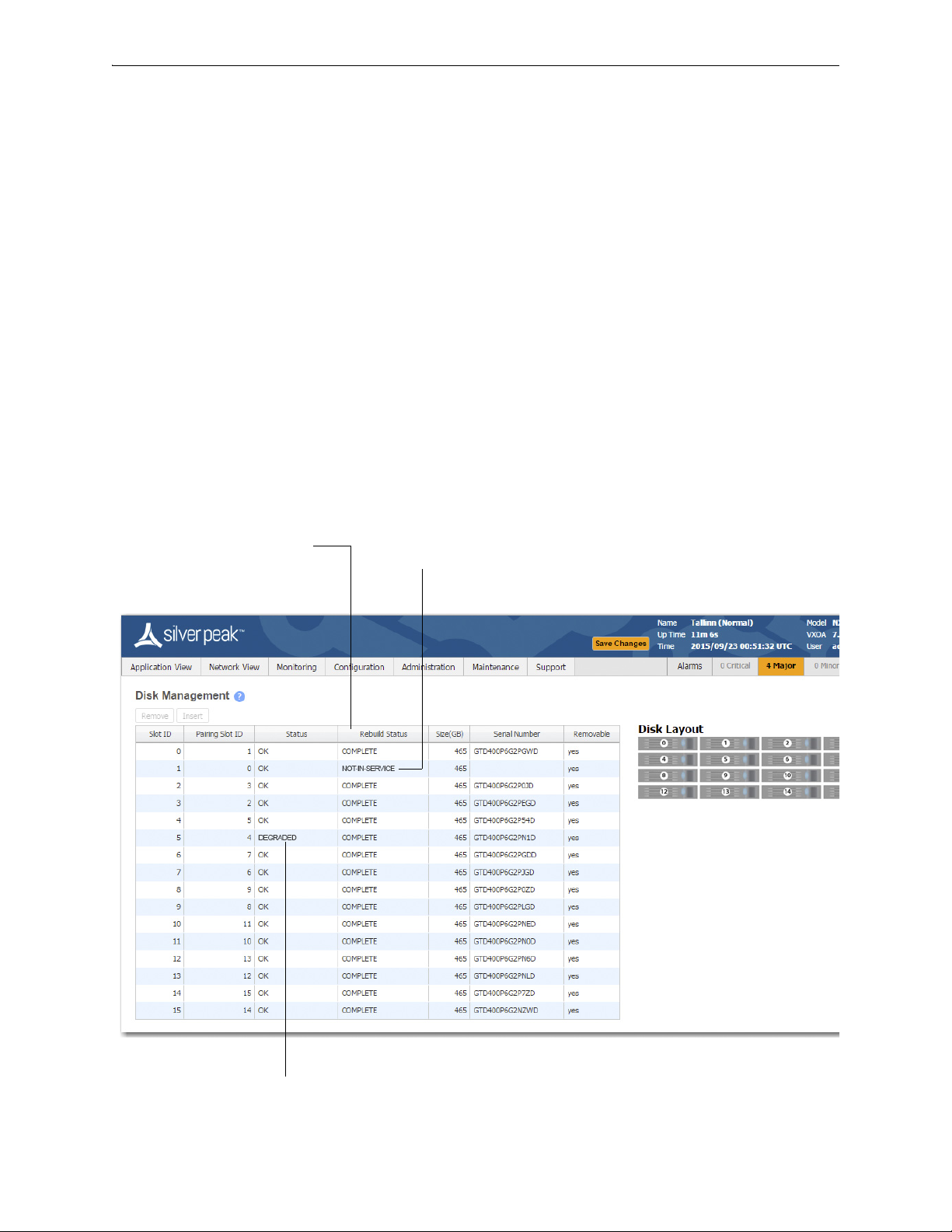
Displays the progress of a new disk that’s
being rebuilt from its array partner.
If a disk has been physically removed, the
Status is NOT-IN-SERVICE and no
Serial Number displays.
If a disk’s Status is DEGRADED, you
need to Remove it from the database,
Using Appliance Manager
The appliances use RAID arrays with encrypted disks. RAID stands for Redundant Array of Independent
(or Inexpensive) Disks, a category of disk drives that ensures recoverability by mirroring data on paired
hard drives.
Disk failure results in a critical alarm, and the specific disk’s LED stops illuminating on the appliance.
Follow this procedure when replacing a failed disk:
1 Log into your Support portal account, and click
2 Complete the wizard, using the serial number of the appliance (not the disk).
3 After you receive the new disk, go to the
4 Select the failed disk's row in the table and click
5 Physically remove the old disk from the appliance.
6 Physically insert the new disk.
7 In the table, select the new disk and click
Open a Self Service RMA for disk replacement.
Maintenance - Disk Management page.
Remove. This takes the disk off-line.
Insert. This prompts the software to discover the disk and
put it online.
2 PN 200972-001 Rev B

Physically Replacing a Disk Chapter 1 Replacing an HDD or SSD
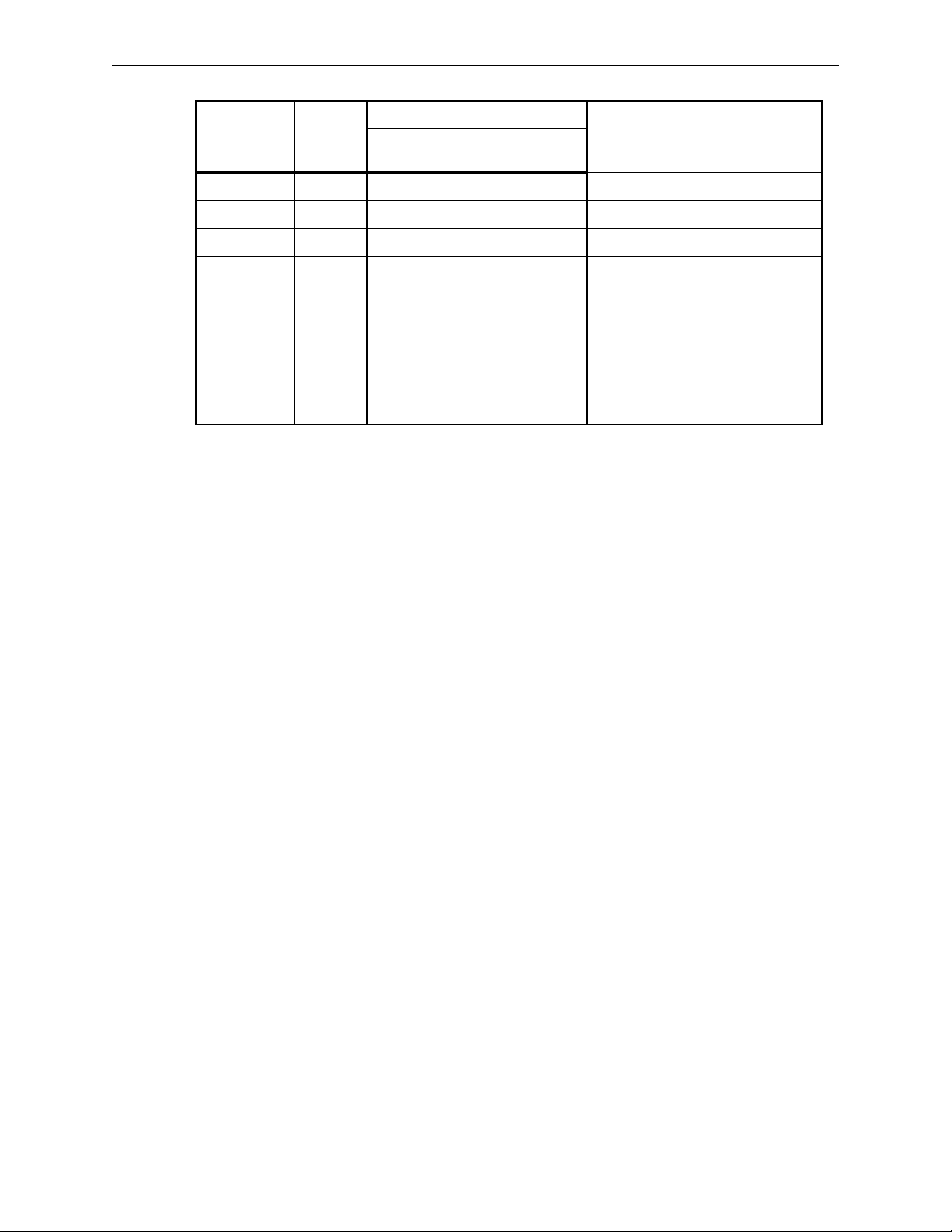
Physically Replacing a Disk
This section provides the model-specific procedures for using Appliance Manager to replace an HDD or
SSD.
HDD or SSD
Part
Model
EC-XS 200889 1 no -- --
EC-S 200877 1 no -- --
EC-M 200890 2 yes yes “Disk Instruction Set A” on page 5
EC-L 200883 2 yes yes “Disk Instruction Set A” on page 5
EC-L-NM 200887 8 yes yes “Disk Instruction Set A” on page 5
EC-XL 200884 2 yes yes “Disk Instruction Set A” on page 5
EC-XL-NM 200888 6 yes yes “Disk Instruction Set A” on page 5
NX-700 200849 1 no -- --
NX-1700 AC 200404 1 no -- --
NX-1700 AC 200576 1 no -- --
NX-1700 200863 1 no -- --
NX-1700 DC 200464 1 no -- --
NX-2600 200178 1 no -- --
NX-2610 200193 2 yes no “Disk Instruction Set F” on page 16
NX-2700 200401 2 yes yes “Disk Instruction Set C” on page 10
Number
Allow user
to replace
Hot
swappable
Where to findQty
NX-2700 200697 2 yes yes “Disk Instruction Set A” on page 5
NX-3600 200348 2 yes no “Disk Instruction Set E” on page 15
NX-3700 200400 2 yes yes “Disk Instruction Set C” on page 10
NX-3700 200698 2 yes yes “Disk Instruction Set A” on page 5
NX-5600 200231 8 yes yes “Disk Instruction Set D” on page 13
NX-5700 200399 8 yes yes “Disk Instruction Set C” on page 10
NX-5700 200699 8 yes yes “Disk Instruction Set A” on page 5
NX-6700 200828 8 yes yes “Disk Instruction Set A” on page 5
NX-7600 200225 12 yes yes “Disk Instruction Set D” on page 13
NX-7700 200398 10 yes yes “Disk Instruction Set C” on page 10
NX-7700 200702 8 yes yes “Disk Instruction Set A” on page 5
NX-8600 200181 16 yes yes “Disk Instruction Set D” on page 13
NX-8700
NX-8700 200767 14 yes yes “Disk Instruction Set B” on page 8
NX-8700 200879 8 yes yes “Disk Instruction Set A” on page 5
a
200397 14 yes yes “Disk Instruction Set C” on page 10
PN 200972-001 Rev B 3
Silver Peak Hardware Reference Guide Physically Replacing a Disk
HDD or SSD
Model
Part
Number
Allow user
to replace
Hot
swappable
Where to findQty
NX-9610 200362 16 yes yes “Disk Instruction Set D” on page 13
NX-9700
a
200396 14 yes yes “Disk Instruction Set C” on page 10
NX-9700 200768 14 yes yes “Disk Instruction Set B” on page 8
NX-9700 200880 8 yes yes “Disk Instruction Set A” on page 5
NX-10700 200519 18 yes yes “Disk Instruction Set C” on page 10
NX-10700 200769 18 yes yes “Disk Instruction Set B” on page 8
NX-10700 200881 6 yes yes “Disk Instruction Set A” on page 5
NX-11700 200711 18 yes yes “Disk Instruction Set B” on page 8
NX-11700 200882 6 yes yes “Disk Instruction Set A” on page 5
a. Two disk configurations — regular and “v”
4 PN 200972-001 Rev B
Physically Replacing a Disk Chapter 1 Replacing an HDD or SSD
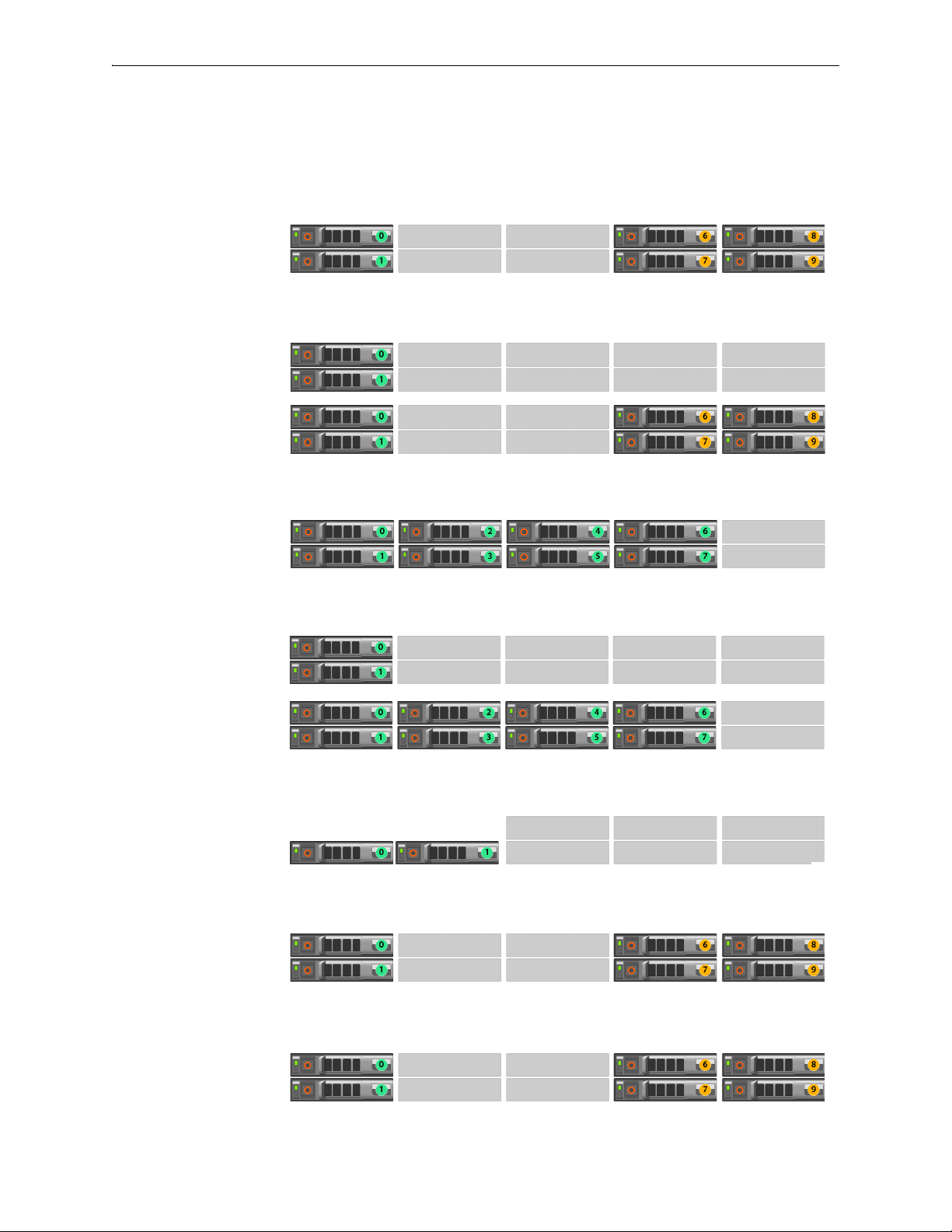
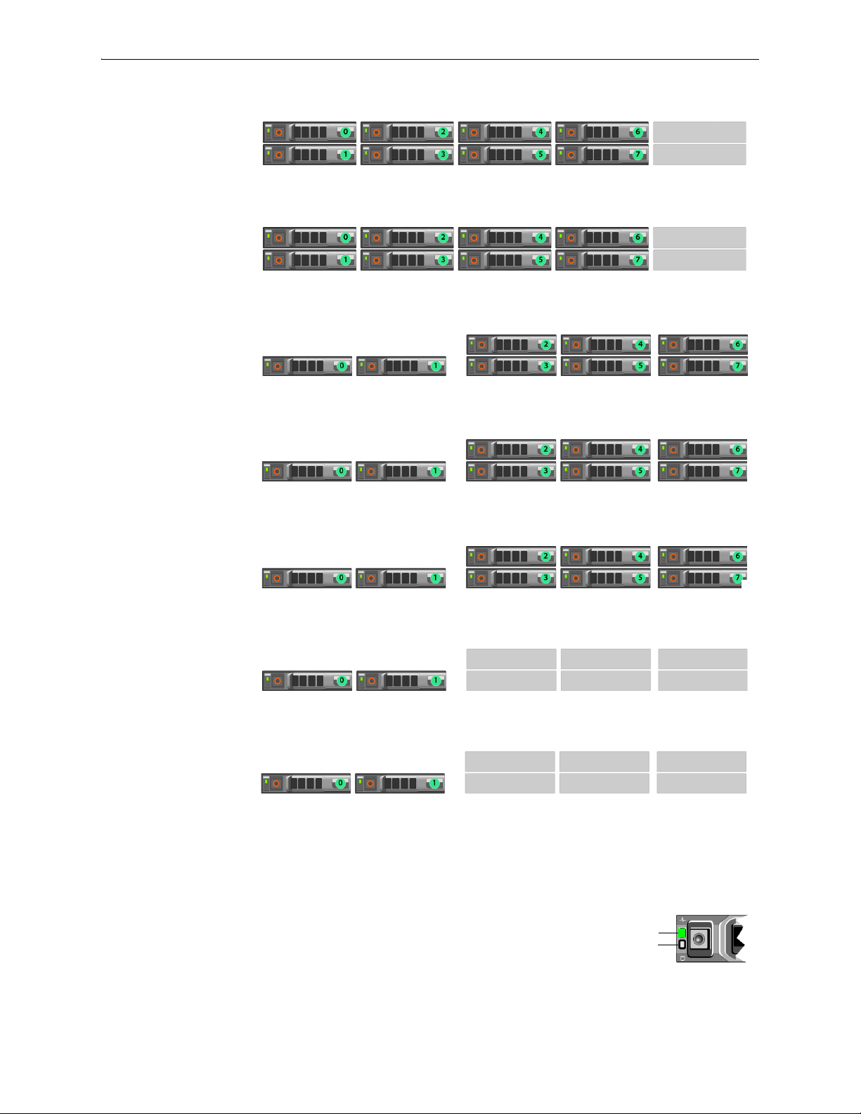
Disk Instruction Set A
These appliances’ drives are hot-swappable.
The first disk on the left is Disk 0. The numbers increment by one from left to right.
EC-XL-NM
[PN 200888]
Drives: 2 SSD + 4 NVMe
EC-XL
[PN 200884]
Drives:
Default = 2 SSD
Optional = 2 SSD + up to
4 NVMe
EC-L-NM
[PN 200887]
Drives: 8 SSD
EC-L
[PN 200883]
Drives:
Default = 2 SSD
Optional = up to 8 SSD
EC-M
[PN 200890]
Drives: 2 SSD
NX-11700
[PN 200882]
Drives: 2 SSD + 4 NVMe
NX-10700
[PN 200881]
Drives: 2 SSD + 4 NVMe
PN 200972-001 Rev B 5
Silver Peak Hardware Reference Guide Physically Replacing a Disk
Status
Activity
Drive online
NX-9700
[PN 200880]
Drives: 8 SSD
NX-8700
[PN 200879]
Drives: 8 SSD
NX-7700
[PN 200702]
Drives: 8 SSD
NX-6700
[PN 200828]
Drives: 8 SSD
NX-5700
[PN 200699]
Drives: 8 SSD
NX-3700
[PN 200698]
Drives: 2 SSD
NX-2700
[PN 200697]
Drives: 2 SSD
1 To take the disk off-line, go to the Maintenance - Disk Management page, select the disk, and click
Remove.
If the SSD is online, the green activity/fault indicator flashes as the drive
is turned off. When the SSD indicators are off, the SSD is ready for
removal.
6 PN 200972-001 Rev B

Physically Replacing a Disk Chapter 1 Replacing an HDD or SSD
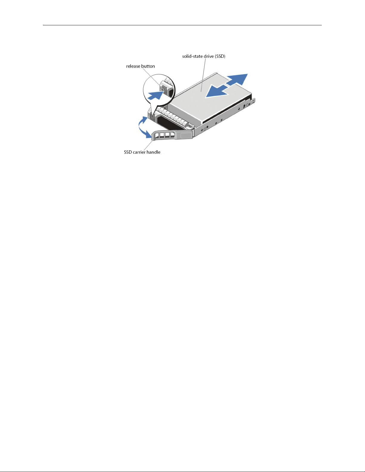
2 Press the release button to open the SSD carrier release handle.
3 Slide the SSD carrier out until it is free of the hard-drive slot.
4 Press the release button on the front of the SSD carrier and open the SSD carrier handle.
5 Insert the SSD carrier into the SSD slot until the carrier connects with the backplane.
6 Close the SSD carrier handle to lock the SSD in place.
7 To put the disk back online, go to the
click
Insert.
Maintenance - Disk Management page, select the disk, and
PN 200972-001 Rev B 7

Silver Peak Hardware Reference Guide Physically Replacing a Disk
Status
Activity
Drive online
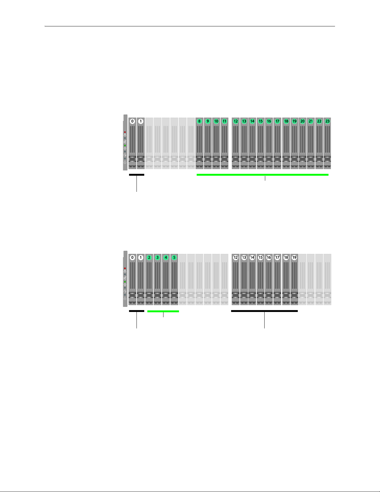
Disk Instruction Set B
These appliances’ drives are hot-swappable.
The first disk on the left is Disk 0. The numbers increment by one from left to right.
NX-11700
[PN 200711]
Drives: 18 SSD
NX-10700
[PN 200769]
Drives: 18 SSD
NX-9700
[PN 200768]
Drives: 14 SSD
NX-8700
[PN 200767]
Drives: 14 SSD
1 To take the disk off-line, go to the
Remove.
Maintenance - Disk Management page, select the disk, and click
If the SSD is online, the green activity/fault indicator flashes as the drive
is turned off. When the SSD indicators are off, the SSD is ready for
removal.
8 PN 200972-001 Rev B
Physically Replacing a Disk Chapter 1 Replacing an HDD or SSD
2 Press the release button to open the SSD carrier release handle.
3 Slide the SSD carrier out until it is free of the SSD slot.
4 Press the release button on the front of the SSD carrier and open the SSD carrier handle.
5 Insert the SSD carrier into the SSD slot until the carrier connects with the backplane.
6 Close the SSD carrier handle to lock the SSD in place.
7 To put the SSD online, go to the
Insert.
Maintenance - Disk Management page, select the disk, and click
PN 200972-001 Rev B 9
Silver Peak Hardware Reference Guide Physically Replacing a Disk
Solid-state disks
SATA hard
disk drives
Note that the NX-10700 appliances contain a mix of SATA
hard disk drives and SSDs (solid-state drives).
Solid-state disks
SATA hard
disk drives
SATA hard
disk drives
Note that the NX-9700 and NX-8700 appliances contain a mix
of SATA hard disk drives and SSDs (solid-state drives).
Disk Instruction Set C
The first disk on the left is Disk 0. The numbers increment by one from left to right.
These appliances’ hard disks are hot-swappable.
The NX-9700 and NX-8700 have two possible backplane configurations. The newer revision was
released in March 2011.
NX-10700
[PN 200519]
Drives: 2 HDD + 16 SSD
NX-9700
[PN 200396]
NX-8700
[PN 200397]
Drives: 10 HDD + 4 SSD
Release -001
10 PN 200972-001 Rev B
Physically Replacing a Disk Chapter 1 Replacing an HDD or SSD
Solid-state disks
SATA hard
disk drives
SATA hard
disk drives
Note that the NX-9700 and NX-8700 appliances contain a mix
of SATA hard disk drives and SSDs (solid-state drives).
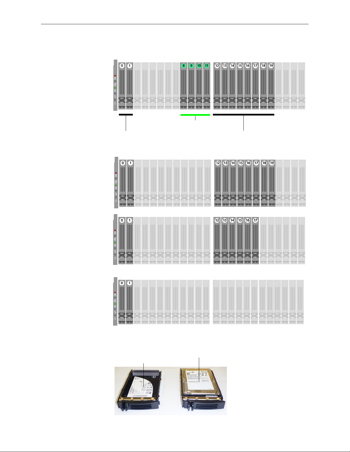
Solid-state drive (SSD)
with spacer
SATA hard disk drive
NX-9700
[PN 200396]
NX-8700
[PN 200397]
Drives: 10 HDD + 4 SSD
Release -002
· March 2011 ·
NX-7700
[PN 200398]
Drives: 10 HDD
NX-5700
[PN 200399]
Drives: 8 HDD
NX-3700
[PN 200400]
NX-2700
[PN 200401]
Drives: 2 HDD
These are the two types of disk drives:
PN 200972-001 Rev B 11

Silver Peak Hardware Reference Guide Physically Replacing a Disk
Pinch the latch together. Grasp the tab and pull forward to release.
Push the top of the disk inward until it clicks into place. Push the latch against the tray to secure it.
1 To take the disk off-line, go to the Maintenance - Disk Management page, select the disk, and click
Remove.
2 Unlatch the carrier by pinching the latch together and then pulling the tab towards yourself.
3 Pull the disk out of its slot.
4 Insert the new disk and push until it clicks into place.
5 To put the disk back online, go to the
click
Insert.
Maintenance - Disk Management page, select the disk, and
The hard drive powers up.
12 PN 200972-001 Rev B
Physically Replacing a Disk Chapter 1 Replacing an HDD or SSD
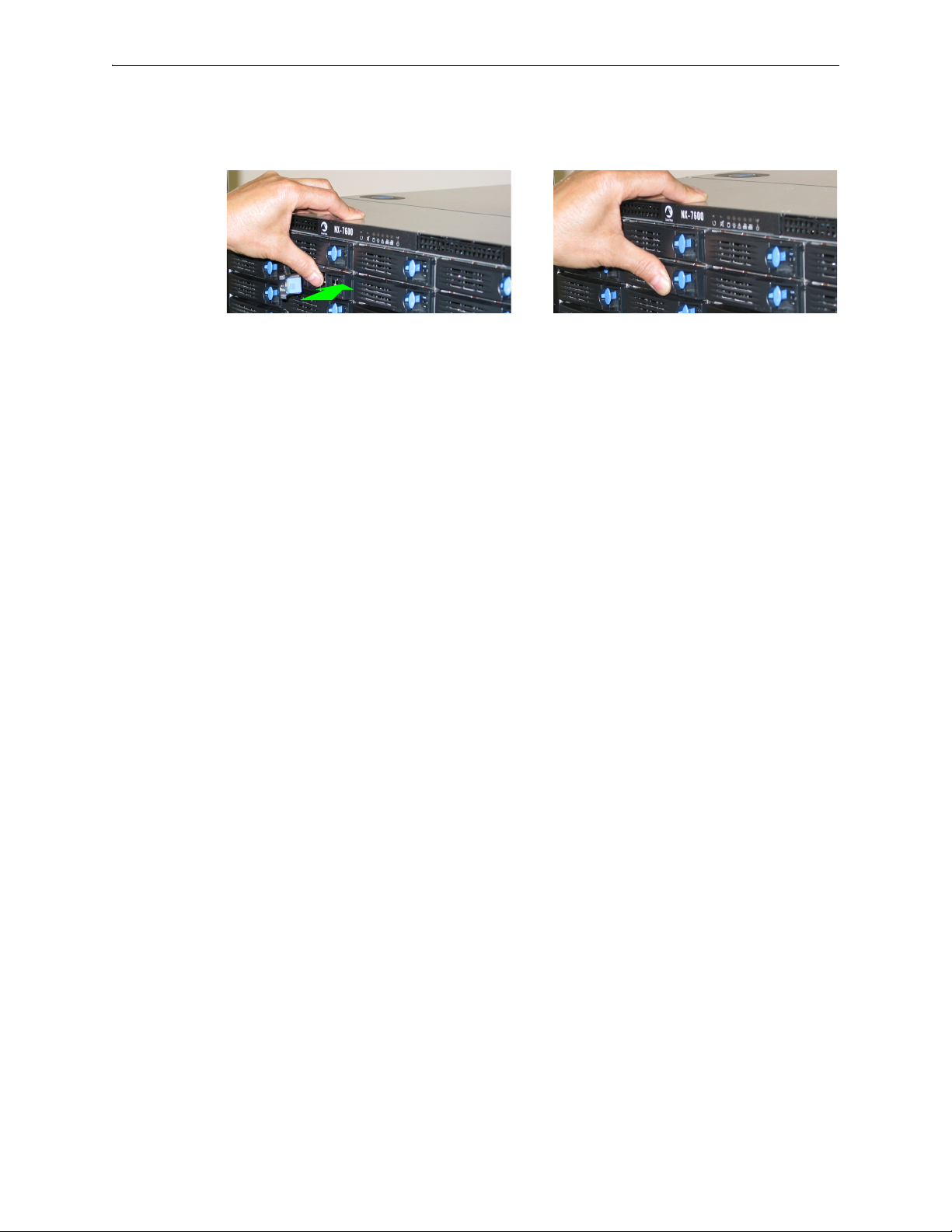
Depress the blue button leftward, into the tab. Slip your finger behind the tab and pull
forward to release.
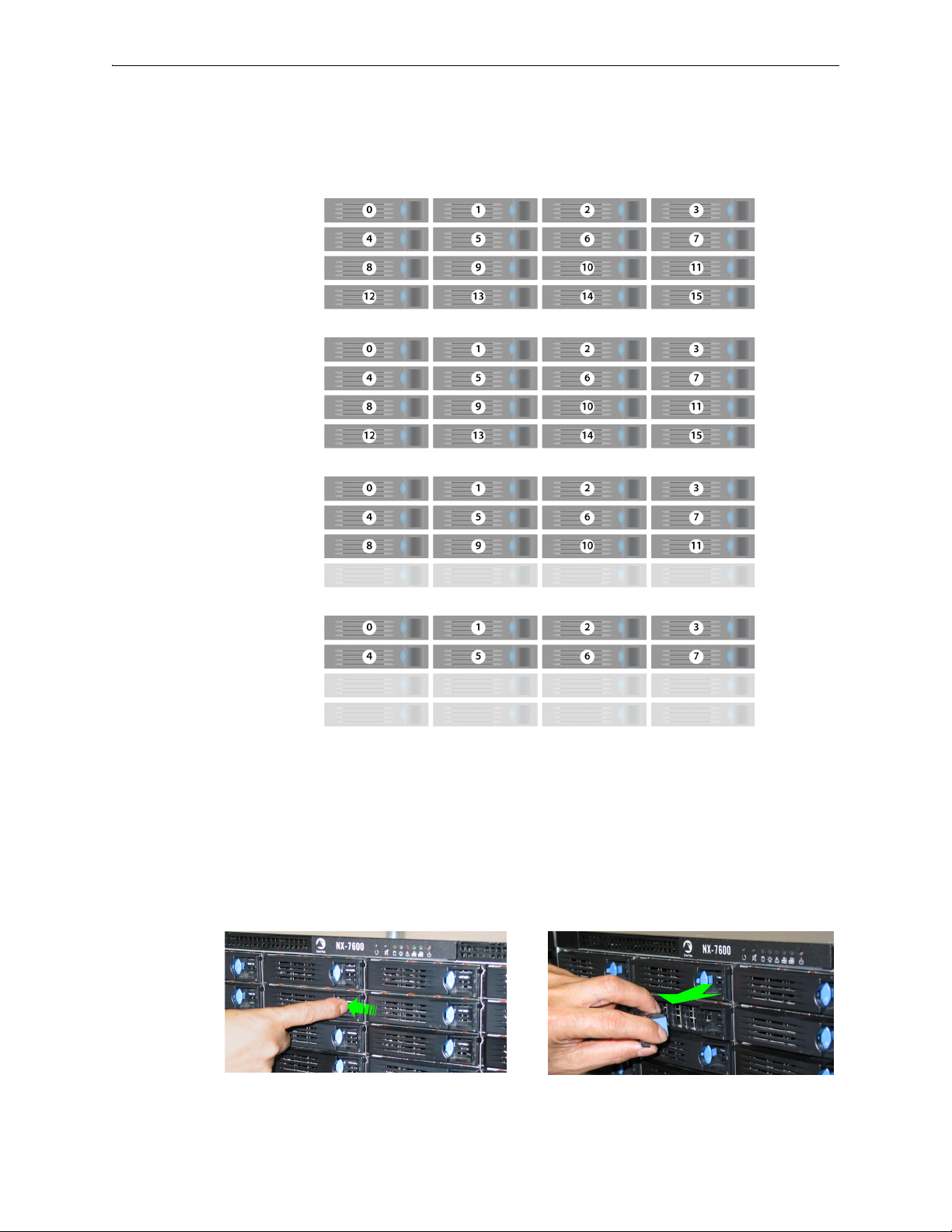
Disk Instruction Set D
These appliances’ disk drives are hot-swappable.
The first disk on the left is Disk 0. The numbers increment by one from left to right.
NX-9610
[PN 200362]
Drives: 16 HDD
NX-8600
[PN 200181]
Drives: 16 HDD
NX-7600
[PN 200225]
Drives: 12 HDD
NX-5600
[PN 200231]
Drives: 8 HDD
1 To take the disk off-line, go to the
Remove.
Maintenance - Disk Management page, select the disk and click
2 Unlatch the hard drive by pressing the end of the blue button toward the left and then pulling the tab
towards yourself.
3 Pull the disk out of its slot.
PN 200972-001 Rev B 13
Silver Peak Hardware Reference Guide Physically Replacing a Disk
Push the tray inward until it clicks into place. Push the tab against the tray to secure it.
4 Insert the new disk and push until it clicks into place.
5 To put the disk back online, go to the
Insert.
The drive powers up.
Maintenance - Disk Management page, select the disk and click
14 PN 200972-001 Rev B
Physically Replacing a Disk Chapter 1 Replacing an HDD or SSD
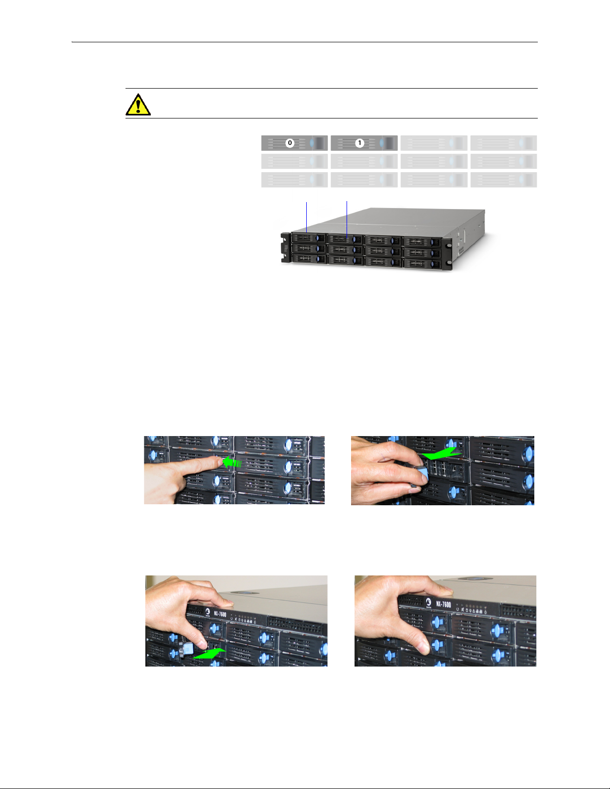
Disk 0 Disk 1
NX-3600
[PN 200348]
Drives: 2 HDD
Depress the blue button leftward, into the tab. Slip your finger behind the tab and pull
forward to release.
Although these photos show the NX-7600, the physical motions required to remove and re-insert the
disks are accurate for the NX-3600.
Push the tray inward until it clicks into place. Push the tab against the tray to secure it.
Disk Instruction Set E
CAUTION The NX-3600’s hard disks are NOT hot-swappable.
1 To take the disk off-line, go to the Maintenance - Disk Management page, select the disk, and click
Remove.
2 Power down the appliance by going to the
Shutdown.
Maintenance - Restart System page and clicking
3 After the NX appliance powers down, unlatch the hard drive by pressing the end of the blue button
toward the left and then pulling the tab towards yourself.
4 Pull the disk out of its slot.
5 Insert the new disk and push until it clicks into place.
PN 200972-001 Rev B 15
6 Power up the appliance by pressing the
7 To put the disk back online, go to the
Insert.
Maintenance - Disk Management page, select the disk and click
Power button on the front left side of the appliance.
Silver Peak Hardware Reference Guide Physically Replacing a Disk
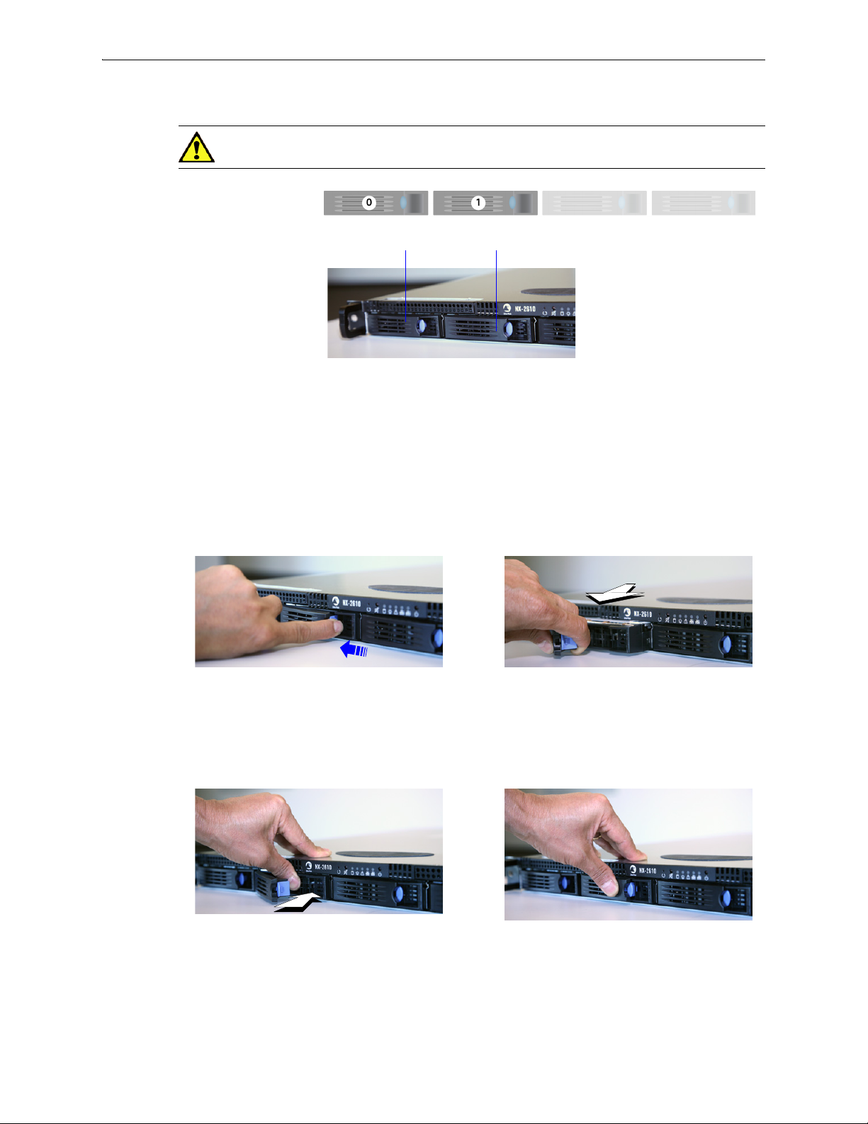
Disk 0 Disk 1
NX-2610
[PN 200193]
Drives: 2 HDD
Depress the blue button leftward, into the tab.
Slip your finger behind the tab and pull
forward to release.
Push the tray inward until it clicks into place.
Push the tab against the tray to secure it.
Disk Instruction Set F
CAUTION The NX-2610’s hard disks are NOT hot-swappable.
1 To take the disk off-line, go to the Maintenance - Disk Management page, select the disk, and click
Remove.
2 Power down the appliance by going to the
Shutdown.
Maintenance - Restart System page and clicking
3 After the drive powers down, unlatch the hard drive by pressing the end of the blue button toward
the left and then pulling the tab towards yourself.
4 Pull the disk out of its slot.
5 Insert the new disk and push until it clicks into place.
16 PN 200972-001 Rev B
6 Power up the appliance.
7 To put the disk back online, go to the
Insert.
Maintenance - Disk Management page, select the disk and click
CHAPTER 2
Replacing a Power Supply
This chapter describes how to replace a power supply for those appliances for which the customer is
authorized to make the replacement.
CAUTION Silver Peak does NOT authorize the customer to replace the power supplies in the
EC-XS, EC-S, NX-700, NX-1700, NX-2600, or NX-2610. Replacing it voids the warranty.
WARNING Do not open the casing of a power supply. Opening the casing of a power supply
voids the warranty. Only a qualified technician from the manufacturer has the authority to access
and/or service power supplies.
In This Chapter
Power Supply Instruction Set A See page 19.
Power Supply Instruction Set B See page 20.
Power Supply Instruction Set C See page 21.
PN 200972-001 Rev B 17

Silver Peak Hardware Reference Guide
The following table summarizes information about replacing redundant power supplies in authorized
appliance models:
Power Supplies
Model
Part
Number
Allow user
to replace
Hot
swappable
Where to findQty
EC-M 200890 2 yes yes “Power Supply Instruction Set A” on page 19
EC-L 200883 2 yes yes “Power Supply Instruction Set A” on page 19
EC-L-NM 200887 2 yes yes “Power Supply Instruction Set A” on page 19
EC-XL 200884 2 yes yes “Power Supply Instruction Set A” on page 19
EC-XL-NM 200888 2 yes yes “Power Supply Instruction Set A” on page 19
NX-2700 200401 2 yes yes “Power Supply Instruction Set C” on page 21
NX-2700 200697 2 yes yes “Power Supply Instruction Set A” on page 19
NX-3600 200348 2 yes yes “Power Supply Instruction Set C” on page 21
NX-3700 200400 2 yes yes “Power Supply Instruction Set C” on page 21
NX-3700 200698 2 yes yes “Power Supply Instruction Set A” on page 19
NX-5600 200231 3 yes yes “Power Supply Instruction Set C” on page 21
NX-5700 200399 2 yes yes “Power Supply Instruction Set C” on page 21
NX-5700 200699 2 yes yes “Power Supply Instruction Set A” on page 19
NX-6700 200828 2 yes yes “Power Supply Instruction Set A” on page 19
NX-7600 200225 3 yes yes “Power Supply Instruction Set C” on page 21
NX-7700 200398 2 yes yes “Power Supply Instruction Set C” on page 21
NX-11700 200702 2 yes yes “Power Supply Instruction Set A” on page 19
NX-8600 200181 3 yes yes “Power Supply Instruction Set C” on page 21
NX-8700
a
200397 2 yes yes “Power Supply Instruction Set C” on page 21
NX-8700 200767 2 yes yes “Power Supply Instruction Set B” on page 20
NX-8700 200879 2 yes yes “Power Supply Instruction Set A” on page 19
NX-9610 200362 3 yes yes “Power Supply Instruction Set C” on page 21
NX-9700
a
200396 2 yes yes “Power Supply Instruction Set C” on page 21
NX-9700 200768 2 yes yes “Power Supply Instruction Set B” on page 20
NX-9700 200880 2 yes yes “Power Supply Instruction Set A” on page 19
NX-10700 200519 2 yes yes “Power Supply Instruction Set C” on page 21
NX-10700 200769 2 yes yes “Power Supply Instruction Set B” on page 20
NX-10700 200881 2 yes yes “Power Supply Instruction Set A” on page 19
NX-11700 200711 2 yes yes “Power Supply Instruction Set B” on page 20
200882 2 yes yes “Power Supply Instruction Set A” on page 19
a. Two disk configurations — regular and “v”
18 PN 200972-001 Rev B
Power Supply Instruction Set A Chapter 2 Replacing a Power Supply
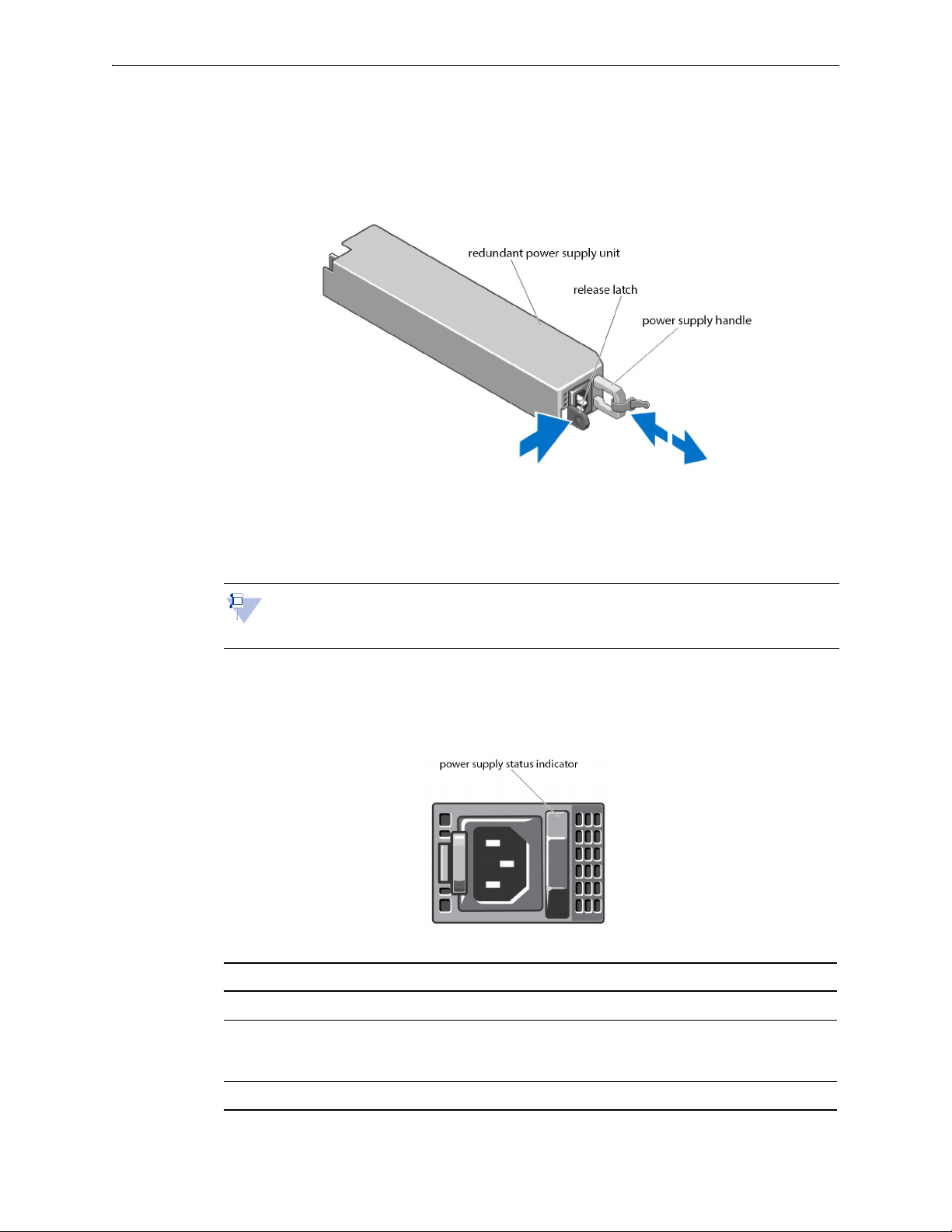
Power Supply Instruction Set A
1 Disconnect the power cable from the power source and the power supply you intend to remove.
2 Press the release latch and pull the power supply straight out to release it from the power distribution
board and clear the chassis.
3 Slide the new power supply into the chassis until the power supply is fully seated and the release
latch snaps into place.
4 Connect the power cable to the power supply and plug the cable into a power outlet.
Note When hot-swapping a new power supply, allow several seconds for the system to
recognize the power supply and determine its status. The power-supply status indicator turns
green to signify that the power supply is functioning properly.
Power Indicator Codes
Each power supply has an illuminated translucent handle that serves as an indicator to show whether
power is present or whether a power fault has occurred.
Power Indicator Pattern Condition
Not lit Power is not connected.
Green The handle/LED indicator illuminates green to indicate that a valid power
source is connected to the power supply and that the power supply is
operational.
Flashing amber Indicates a problem with the power supply. Contact Silver Peak Support.
PN 200972-001 Rev B 19
Silver Peak Hardware Reference Guide Power Supply Instruction Set B
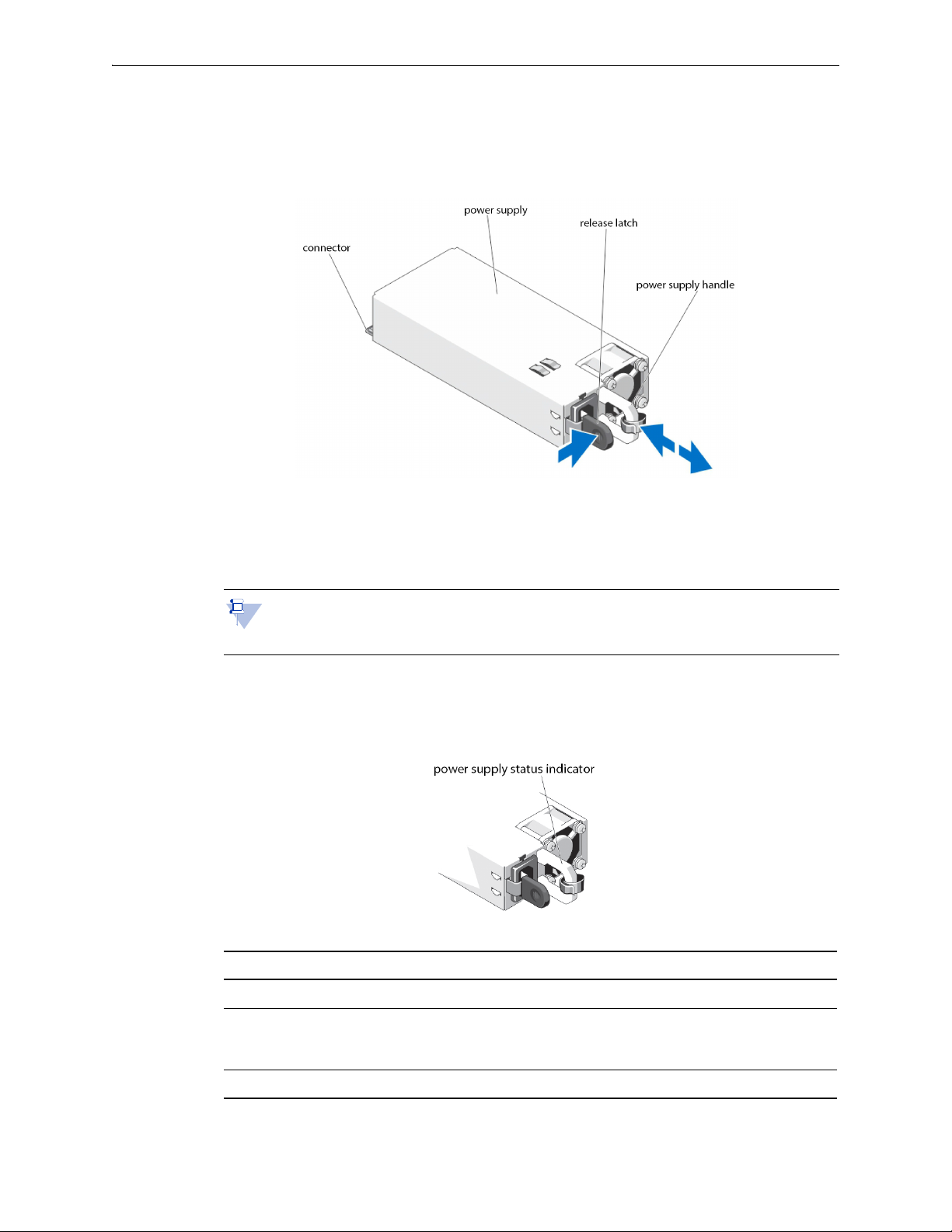
Power Supply Instruction Set B
1 Disconnect the power cable from the power source and the power supply you intend to remove.
2 Press the release latch and slide the power supply out of the chassis.
3 Slide the new power supply into the chassis until the power supply is fully seated and the release
latch snaps into place.
4 Connect the power cable to the power supply and plug the cable into a power outlet.
Note When hot-swapping a new power supply, allow several seconds for the system to
recognize the power supply and determine its status. The power-supply status indicator turns
green to signify that the power supply is functioning properly.
Power Indicator Codes
Each power supply has an illuminated translucent handle that serves as an indicator to show whether
power is present or whether a power fault has occurred.
Power Indicator Pattern Condition
Not lit Power is not connected.
Green The handle/LED indicator illuminates green to indicate that a valid power
source is connected to the power supply and that the power supply is
operational.
Flashing amber Indicates a problem with the power supply. Contact Silver Peak Support.
20 PN 200972-001 Rev B

Power Supply Instruction Set C Chapter 2 Replacing a Power Supply
2. To release the power supply from its
locking position, squeeze the screw
and the release tab together. Then
hold it there while you ....
1. Turn the screw counter-clockwise to loosen it.
3. ...grip the handle to remove
the power supply from the
chassis.
4. Once the power supply
module is released from its
locking position, remove it
from the chassis.
The
release
tab
Power Supply Instruction Set C
CAUTION Unplug the power cord before removing the power supply!!!
Note The photos are of the NX-x600 series. The power supplies in the NX-x700 appliances
look recognizably similar.
The NX-3600 power supplies are oriented 90° counterclockwise from these photos.
To access the power supply
Locate the release tab on the right side of the power supply.
PN 200972-001 Rev B 21
To insert a new power supply, repeat the procedure in reverse.

Silver Peak Hardware Reference Guide Power Supply Instruction Set C
22 PN 200972-001 Rev B
CHAPTER 3
Replacing a Fiber Interface Module
The following fiber-interface appliance models with have the option to separately order LR (Long
Reach) 10 Gbps Fiber Interfaces to replace the default SR (Short Reach) modules:
Model Part Number
NX-11700 200711
NX-10700 200519
NX-10700 200769
NX-9700 200768
NX-9700 200396
For the models listed above, Silver Peak supports different module combinations. For example, you
may have an SR (Short Reach) interface for the LAN side and an LR (or Long Reach) for the WAN.
These modules are hot-swappable.
This chapter describes how to replace the modules.
WARNING If you don’t turn off the power while replacing the module, be sure to protect your
eyes from exposure to the laser by being careful to avoid looking directly into the interface
housing.
PN 200972-001 Rev B 23
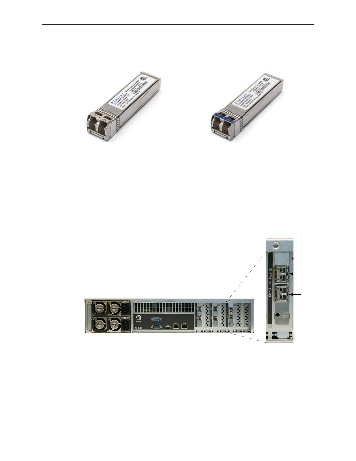
Silver Peak Hardware Reference Guide
Module’s handle is on the right side.
You can distinguish the SR module from the LR module by the number on the label and the color of the
handle.
FTLX8571D3BCL — SR — Short Reach
• Bail (handle) is beige
• Default shipping module
To replace a fiber interface module
1 Locate the fiber interface(s).
FTLX1471D3BCL — LR — Long Range
• Bail (handle) is blue
• Optional, separate purchase
24 PN 200972-001 Rev B