

Silver Mountain Targets USA
3393 S. Keller Road
Crawfordsville, IN 47933
www.SilverMountainTargetsUSA.com
Dave@SilverMountainTargetsUSA.com
Steve@SilverMountainTargetsUSA.com
Quick Setup Guide SOLO-Pac Targets & Server
For help with the Solo-Pac targets utilizing a Server, call Dave at 765-427-2753 or Steve at 765-427-
4699. Also, detailed instructions on the use of the Server can be found in the “Admin Guide SOLO
Server System”. Charge Your Batteries Now
Target Frame
You’ll need to have a suitable target frame for mounting each SOLO system. It can be a manually
operated “pit” system, or a fixed frame. A solid frame is the key to repeatable accuracy. You can
mount the target equipment on an existing frame, or build a new frame.
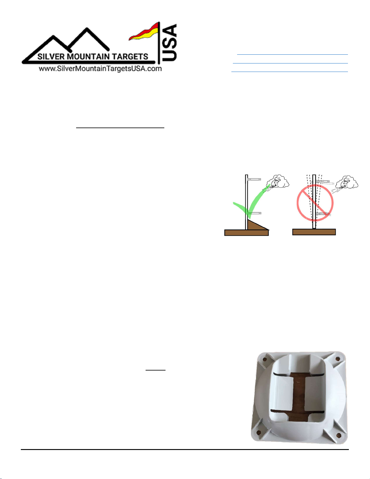
1. Your frame should be solid, and not move excessively with
wind or bullet impacts. It should be mounted securely, or
have a rigid stand if it’s portable.
2. It should be large enough so sensors don’t get shot and you
can easily mount your largest targets. The T-SOLO and
the lower sensor elements should be mounted below
grade, out of the line of fire.
3. Cardboard or corrugated plastic (more weather resistant) work well for a backer board. Coroplast
is available at most home improvement stores.
The microphone sensor elements are mounted in the four corners of your target frame, and the T-
SOLO is mounted near the bottom of your frame, out of the line of fire. The T-SOLO panel
antenna communicates to the line, and needs to be mounted about 1/3 or 1/2 way up the left side of
the frame, with clear line of sight to the firing line. The lower sensor elements should ideally also be
below the line of fire if you have pits.
Sensor Mounting Plates
Good, accurate sensor mounting is the key to an accurate system. There are four white plastic
mounting plates that get mounted to the four corners of the target frame. The SOLO dual-mic
sensor elements then connect to these mounting plates with a simple slide down from the top.
1. Mount these 4 bases to your target using 4 pan head screws per
base, and do not over tighten. You MUST install the bases at 90
degrees to each other, so they should be rectangular or square.
2. Attach the microphone sensor assemblies to the bases. The
sensors are not specific to any corner, but the correct color-coded
cable must be attached as shown. They should be mounted in the
same plane as each other and the target face, and point at the
firing line, being parallel to each other.
SOLO Server Quick Setup Guide Rev 1.10 Jan 1, 2019 Page 1
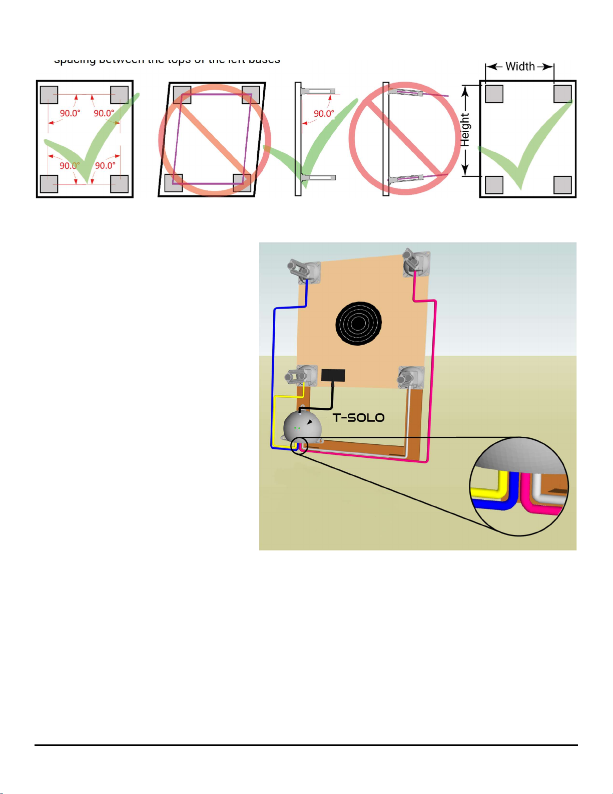
3. Once mounted, record the horizontal spacing between the left edges of upper bases & the vertical
spacing between the tops of the left bases
Targets
Fasten a paper target face to the frame, roughly near the center of the bases
Target Wiring
The T-SOLO is connected to the
sensors with color-coded ethernet
cables. It is imperative that you get the
correct color cable to the correct sensor
and to the correct port on the T-
SOLO.
Next connect the panel antenna cable
to the antenna connection on the T-
SOLO and the panel antenna. Hang
the panel antenna on the left side of the
target frame, about 1/3 or 1/2 way up
the left side. Keep it as far left as
possible to reduce the chance of bullet
impacts.
Connect a freshly charged battery to the
T-SOLO. It needs about 1-2 minutes
to fully come online.
Firing Line
Go to the firing line, connect a freshly charged battery to the Server, and make sure it is on. Face the
large panel antenna toward the targets, and ensure it has clear line of sight to each target’s antenna.
Connecting Your Display Device
Almost any display device with WIFI capability and a modern browser (laptop, tablet, smartphone,
etc.), may be used to connect to the target system.
1. First, connect to the WIFI Network. Choose “Settings”, then “WIFI” or “Connections”, and look for a
WIFI network named SilverMountainTargets, and click “connect”.
2. Open a browser such as Safari, Chrome, or Firefox & in the Address bar, type in the IP address of
the Server, 192.168.0.47. The TargetViewer should now load. Note that older outdated browsers
may not work correctly, so make sure yours is updated.
SOLO Server Quick Setup Guide Rev 1.10 Jan 1, 2019 Page 2

Initial Setup of the System
A software “TargetFrame” corresponds to a physical target frame with attached sensors, and carries
the associated data needed for the server to gather shot data on that frame. A “TargetFrame” is
created by making a copy of an existing frame.
This is needed on initial system installation, or when adding a new target frame. From the Admin
menu, click on the Gear icon, then the Frame & Wrench icon
1. Select any existing target frame by clicking on the target across the bottom of the screen
2. Select the “Copy” button
● A TargetFrame named “new” will be created and selected
● Status = yellow (offline; not connected to a sensing unit)
3. Select the “Rename” button to name the new frame such as “T01” etc. TargetFrames are sorted
alphabetically
4. Choose SOLO as the Wiring Harness type, and the correct Mic mapping and Spacing will
automatically be set.
● SOLO is for a SOLO system
● G2-5mic is for a G2 Controller with 5 mics
● G2-8mic is for a G2 Controller with 8 mics
● PnP is for a Plug-n-Play System with 8 mics
5. Enter Microphone Width and Height values. This is the
distance measured between the left side of the upper or
lower mics, and distance measured between the tops of
the left or right mics. It provides the system with
measurements needed to calculate shot hole
coordinates.
● Measurements need to be entered in mm (25.4 x inches, or 10 x cm)
● No decimals or commas, and a space between the two numbers, i.e., “1330 1635”
6. The “Connect to:” button allows the target selected at the bottom of the screen to be connected to
a particular SOLO target sensing unit. Enter the IP address of the sensing unit such as 112.
● Status should change to GREEN
● “Other SOLO” may be used if sensing unit is not currently online
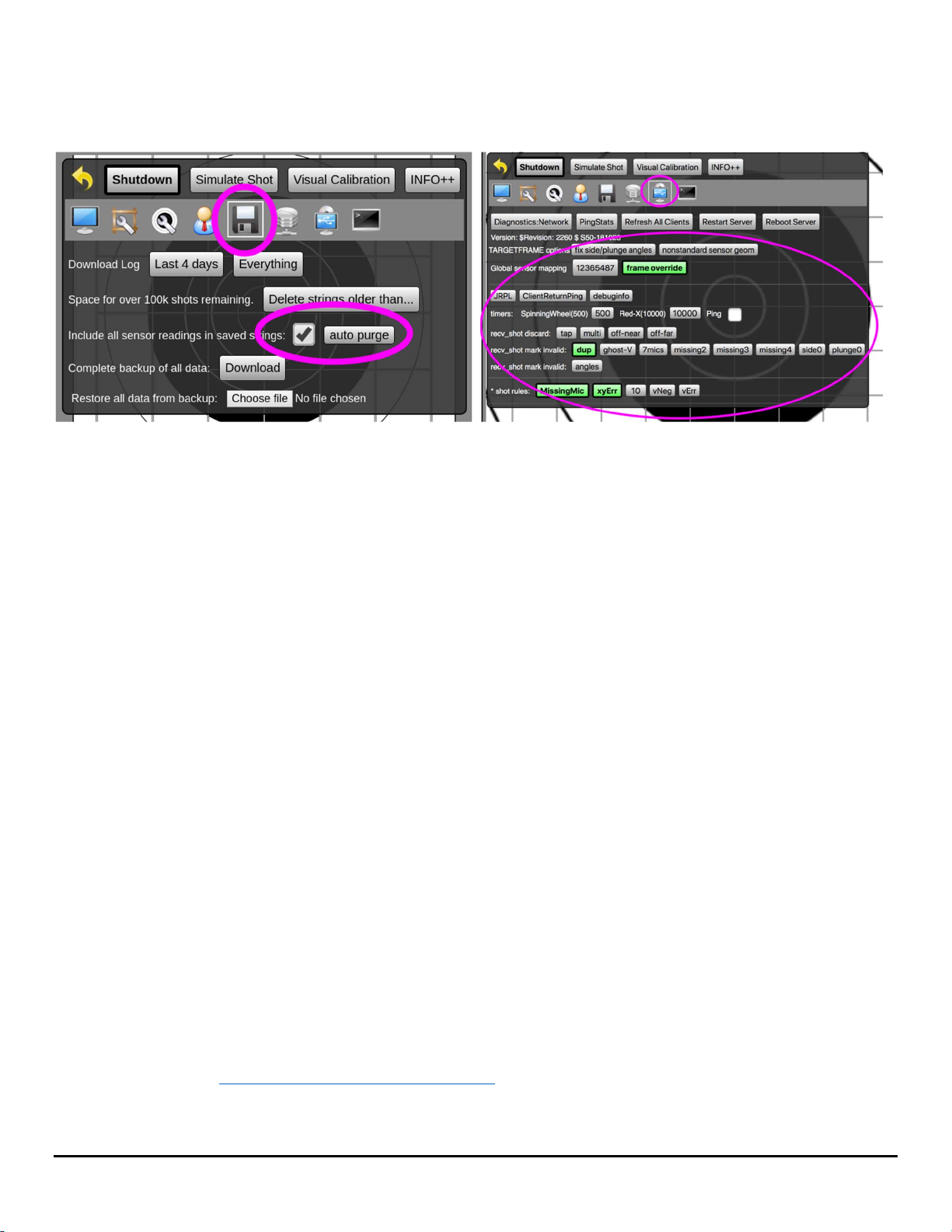
Settings
1. Target Faces: In Admin mode, select the Gear icon, then select the Target & Wrench icon.
You’ll see all the target files loaded in the system. Click on the ones you want to be active to turn
them green.
2. Select Target Face: To select the current face for firing, from the main menu, select the Target &
Wrench icon. Choose from available targets.
3. Course of Fire: From the main menu, choose the Whistle & Wrench icon. This screen
provides the Administrator access to sighters, shots on score, F-Class specifics, user privileges
for managing strings, and scorecard settings.
4. Admin access is only needed for system configuration data, importing, editing, or deleting data
(e.g., adding new hardware, calibration, editing configurations, renaming, etc.). All other common
SOLO Server Quick Setup Guide Rev 1.10 Jan 1, 2019 Page 3
match functions can be performed by a Range Officer. For details on creating RO users, and
specific RO functions, please refer to the “Range Officer’s Guide”.
5. For more details on Admin functions, please refer to “Admin Guide Solo Server System”
6. Recommended Server settings on these two screens
Calibration
Use these procedures to align the e-target’s coordinate system with the physical center of the
installed target face. This should only be required on the first installation of sensor mounts, or if the
physical target center has moved.
1. Set up the physical target frame for shooting, using a new target face, or paste all holes
2. Fire one shot within 10” of the center.
3. Go to the physical target and find the bullet hole in paper
4. From the Admin menu, select the Frame & Wrench icon
5. In the ShotsList Column, select the shot that was fired.
a. Measure the location of the bullet hole center, on the physical target. As an option, you may
draw vertical and horizontal reference lines to assist in measuring
b. Record the bullet position as two numbers, X and Y coordinates.
i. The X coordinate is how many millimeters the bullet is to the RIGHT of the vertical
centerline. If the bullet is LEFT of the vertical centerline, your X coordinate will be a
negative number
ii. The Y coordinate is how many millimeters the bullet is ABOVE the horizontal centerline. If
the bullet is BELOW the horizontal centerline, your Y will be a negative number
c. Click the “Measure” button in the ShotsList column for the calibration shot. Enter your X and Y
values, separated by a space. As an example, “154 73”
d. CONFIRM that the calibration shot is now shown in the correct position. If not, cancel the shot
from the calibration and repeat the calibration by selecting the “measure” button again.
6. Note, shot(s) used for a calibration offset calculation are highlighted in yellow, in both the
ShotsList and screen display
7. The CANCEL button can remove a shot from calibration calculation
For more information, please contact Dave or Steve at Silver Mountain Targets USA, or log onto the
SMT corporate site www.SilverMountainTargets.com
© 2019 All Rights Reserved
SOLO Server Quick Setup Guide Rev 1.10 Jan 1, 2019 Page 4
 Loading...