

Page 1
Users Manual
12V Drill Driver
Product Code 633852
© December 2006
• This guarantee becomes effective at the date of retail purchase.
PLEASE KEEP YOUR RECEIPT.
• If this product develops a fault within 30 days of purchase, return it to the
stockist where it was purchased, with your receipt, stating details of the fault.
You will receive a replacement or refund.
• If this product develops a fault within 3 years of purchase return it to;
Silverline Tools Service Centre
PO Box 2988
Yeovil
BA21 1WU
Include your original receipt, details of the fault, your name and address, place and
date of purchase. We do not refund carriage. All product should be in a suitably
clean and safe state for repair, and should be packaged carefully to prevent damage
or injury during transportation. We may reject unsuitable or unsafe deliveries.
• You must provide proof of purchase before any work can be carried out.
• All work will be carried out by Silverline Tools or its authorised repair agents.
• Any parts which are replaced will become the property of Silverline Tools.
• The repair or replacement of the product will not extend the period of guarantee.
• The repair or replacement of your product under guarantee provides benefits which
are additional to and do not affect your statutory rights as a consumer.
What is covered:
• The repair of the product, if found to be defective due to faulty materials or workmanship
within 3 years of purchase. If any part is no longer available or out of manufacture,
Silverline Tools will replace it with a functional replacement part.
• Use of the product in the UK.
What is not covered:
Silverline Tools does not guarantee repairs required as a result of:
• Normal wear and tear eg blades, brushes, belts, bulbs, batteries etc.
• Accidental damage, faults caused by negligent use or care,
misuse, neglect, careless operation or handling of the product.
• Use of the product for anything other than normal domestic purposes.
• Change or modification of the product in any way.
• Use of parts and accessories which are not Silverline Tools genuine components.
• Faulty installation (except installed by Silverline Tools).
• Repairs or alterations carried out by parties other than
Silverline Tools or its authorised repair agents.
Silverline Tools 3 Year Guarantee
Thank you for choosing this product
Page 2
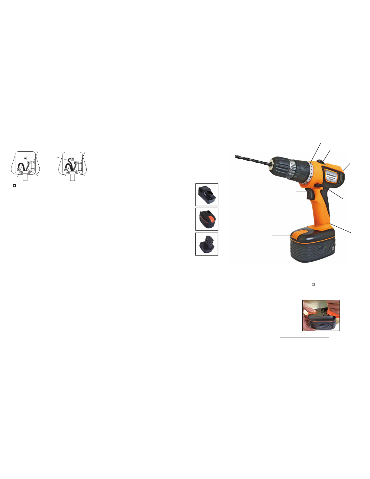
Product Familiarisation
12V Drill Driver
1. Variable speed trigger
2. Keyless chuck
3. Reverse/lock switch
4. Torque control
5. 2 Speed gear switch
6. Magnet
7. 1 Hour Charger
8. Battery
9. Charger adaptor
10. Battery release button
11. Swivel base
8
9
PRIOR TO USE
Inserting and removing bits
This drill has a keyless chuck, hence a chuck key is not needed to
secure a bit in the drill. Always set the forward / reverse control (3)
to the locked 'OFF' position when installing and removing bits. It is
also recommended to remove the battery pack to avoid unintentional
starting.
• Open the chuck jaws by firmly holding the metal back of the chuck
housing and rotating the plastic housing in a anti-clockwise
direction.
Open the jaws so as to fit the desired accessory.
• Ensure the accessory is fully inserted.
• To firmly clamp the accessory in the chuck, grasp the metal back
of the chuck housing and rotate the plastic chuck housing in a
clockwise direction. Ensure the bit is retained firmly or damage to
the chuck jaws can result.
• To remove the accessory, open the chuck jaws by firmly holding
the metal back of the chuck housing and rotating the plastic
housing in an anti-clockwise direction. Open the jaws sufficiently
so as to remove the specific accessory.
Fitting and removing the battery pack
To remove the battery pack from the drill firmly pull the battery
release button (10) at the front of the battery pack, and slide the
battery backward out of the tool.
To install the battery pack
, align rails on the tool with the tabs on the
battery pack and slide the battery pack on to the drill. Ensure the
battery pack is sitting straight on the foot and correctly entering the
runners. The battery should slide fully on to the drill foot until the
battery pack "clicks" into position.
Introduction
Carefully read and understand this manual and any label attached
to the tool before use. Keep these instructions with the product for
future reference. Ensure all persons who use and service this
product are acquainted with this manual.
Electrical Safety Information
• The wires in this product are coloured:
Blue Neutral (N)
Brown Live (L)
Green & Yellow Earth (E)
• As the colours may not correspond with the coloured markings
identifying the terminals in your plug, proceed as follows.
• The wire which is coloured blue must be connected to the
terminal which is marked with the letter N or coloured black, the
wire which is coloured brown must be connected to the terminal
which is marked L or coloured red.
• This appliance must be protected by a suitable fuse.
• To prevent fire or shock hazard, do not expose this product to
rain/water or moisture. There are no user serviceable parts inside
except those referred to in this manual. Always refer servicing to
qualified service personnel. Never remove any part of the casing
unless qualified to do so; this unit contains dangerous voltages.
• Use of a residual current device (RCD) will reduce the risk of
electric shock.
NEVER CONNECT THE BROWN OR BLUE WIRE TO THE
EARTH PIN OF THE 13 AMP PLUG. IF IN DOUBT CONSULT A
QUALIFIED ELECTRICIAN
General Safety Instructions
Even when used as prescribed it is not possible to eliminate all
residual risk factors. Use with caution.
Keep guards in position
• Always keep guards in position, in good working order, correctly
adjusted and aligned. Never attempt to use a power tool without
any guard supplied with it.
Remove adjusting keys
• Always check to see that keys and adjusting wrenches are
removed from power tool before turning on.
Clean work area
• Accidents occur where benches and work areas are cluttered
or dirty, floors must be kept clear, avoid working where the floor is
slippery.
Dangerous environment
• Do not use power tools in damp or wet conditions, or expose
them to rain. Provide adequate surrounding work space and keep
area well lit. Do not use power tools where there is a risk of
explosion or fire from combustible material, flammable liquids,
flammable gases or dust of an explosive nature. When using
power tools avoid contact with any earthed items such as pipes,
radiators, cookers, refrigerators, metal baths and taps.
Children & pets
• Children and pets should always be kept at a safe distance from
your workshop. Lock tools away where children can't get
access to them. Remove batteries from cordless tools.
Use the correct power tool
• Don't force, or attempt to use a power tool for a purpose it was
not designed for. Do not use a small tool to do the job of a heavy
duty tool.
Wear correct clothing and footwear.
• Don't wear loose clothing, neckties or jewellery or other items
which may get caught in moving parts. Wear non-slip footwear,
cover or tie back long hair. Use safety footwear if necessary.
Protect your head
• Wear safety goggles at all times, every day glasses are not
sufficient for eye protection, as lenses are not impact resistant
and could shatter. Use an approved face or dust mask when
operation creates dust. Ensure dust extraction equipment is
functioning and correctly used. Hearing protection should be used
if the sound intensity level for the operator could exceed 85dB(A).
Use a hard hat where there is a risk of falling objects or striking
your head on low level obstructions.
Protect yourself from vibration.
• Hand held power tools may produce vibration. Vibration can
cause disease. Gloves to keep the operator warm and dry and
therefore maintain good blood circulation in the fingers may help.
This tool has not been designed for extended or industrial
operation.
Secure work
• Always secure work. Where practical use a clamp or vice, it will
allow you to use both hands to operate your power tool.
Keep your balance
• Don't over reach, keep proper footing at all times to ensure
correct balance.
Maintain your power tool
• Keep your power tool in good working order, keep tools sharp and
clean for best and safest performance. Ensure ventilation holes
are kept clean and unrestricted at all times.
Always disconnect.
• Before changing tools, always ensure they are disconnected from
the power source.
Accessories
• The use of any attachment or accessory other than those
mentioned in this manual could result in damage or injury. The
use of improper accessories could be dangerous.
Never stand on your power tool
• Standing on your power tool or its stand could cause serious
injury if the tool is tipped or if the cutting tool is accidentally
contacted. Do not store materials above or near the tool so that it
is necessary to stand on the tool or its stand to reach them.
Switch off before connecting.
• Ensure the power tool is switched
off before connecting to the
power source. If the power tool stops unexpectedly turn the power
switch to off.
Do not abuse the power cord.
• Be sure your cable/extension cable is properly wired and in good
condition. Always replace a damaged cable/extension cable or
have it repaired by a qualified person before using it. Never yank
or pull the cable to disconnect it from the power socket. Never
carry your power tool by it’s cable. Keep the cable away from
damp, heat, oil, solvents, and sharp edges.
Check for damaged or missing parts
.
• Before each use check if any part of the power tool is damaged or
missing, check carefully that it will operate properly and perform
its intended function. Check alignment of moving parts for binding.
Any guard or other part that is damaged should be correctly
repaired or replaced. Do not use if the power switch does not turn
the power on and off. Check any other condition that may affect
the safety of the power tool. DO NOT USE IF DEFECTIVE.
Direction of feed
• Feed work into a blade or cutter against the direction of rotation of
the blade or cutter only.
Don’t leave the tool running unattended
• Always wait until your power tool has come to a complete stop
before leaving it and then disconnect from power source.
FUSE
BROWN
(Live)
BLUE
(Neutral)
E
L
N
FUSE
GREEN/YELLOW
OR GREEN
FUSE
BROWN
(Live)
BLUE
(Neutral)
E
L
N
FUSE
Double Insulated
Earthed
4
5
6
1
2
3
SPECIFICATION:
Voltage:
12V
Battery:
12V/1.5Ah Ni-Cad battery
No load speed:
0-350/0-1050RPM
Drilling capacity:
Max in wood:
18mm
Max in steel: 11mm
Weighted vibration: 2.5m/s
2
Sound pressure:
71.3dB
Sound power:
82.3dB
Charger voltage:
230V
Charger frequency:
50Hz
Double insulated:
Fuse rating:
2A
11
10
7
Page 3

Drilling metals
• For maximum performance, use high speed steel bits for metal or
steel drilli
ng.
• Ensure that the torque selection collar (4) is in normal
drilling mode.
• Begin drilling at a very low speed to prevent the bit from slipping
off the starting point.
• Always clamp sheet metal.
• Support thin metal with a block of wood to avoid distorting it.
• Use a punch to mark the centre of the hole.
• Use a suitable lubricant for the material you are working on.
Drilling plastics and plastic coated chipb
oard
• Use high speed drill bits
.
• See drilling wood below
Drilling masonry
• For maximum performance use carbide-tipped masonry impact
bits when drilling holes in brick, tile, concrete etc.
• Turn the torque selector (4) to the drill position.
• Apply light pressure and medium speed for best results in brick.
• Apply additional pressure and high speed for hard materials such
as co
ncrete.
• When drilling holes in tile, practice on a scrap piece to determine
the best speed and pressure.
Drilling wood
• For maximum performance, use high speed steel bits for wood
drilling.
• Ensure that the torque selector (4) is in normal drilling mode.
• Begin drilling at a very low speed to prevent
the bit from slipping
off the starting point. Increase the speed as the drill bites into the
material.
• When drilling through holes, place a block of wood behind the
work piece to prevent ragged or splintered edges on the back of
the hole.
WARNING: Never attempt to lock the trigger switch in the on
position, do not lock the trigger on jobs w
here your hammer
drill may need to be stopped suddenly.
All drilling operations
• Mark off the centre of the hole using a centre punch
or nail.
Use: For:
Oil Steel
Turpentine or paraffin
Aluminium
Do not lubricate Brass, copper or cast iron
Fig.7
Fig.5
Fig.6
Fig.4
Battery charging
Make sure power circuit voltage is the same as that shown on the
charger specification plate. Connect charger to power source. The
green light (A) should light up. This indicates the charger is ready to
begin charging.
Slide battery pack onto the charger adaptor (Fig.2).
Plug the battery and adaptor into the charger unit (Fig.3).
The red light (B) should begin to glow continuously, indicating that
the battery pack is receiving a "fast charge".
After approximately one hour, the "fast charge" indicator red light
(B) should go out indicating that the battery pack is fully charged
and that the charger is now in a "maintenance charge" mode, this is
confirmed by the green light (A) coming on.
Depending on room temperature, line voltage and existing charge
level, initial battery charging may take longer than one hour.
Disconnect charger from power source when not in use.
To obtain the best life for the battery
Never allow the drill to come to a complete stand still before
recharging. The battery should be placed on charge whenever the
battery is noticeably running down or the drill no longer perform a
task it previously performed satisfactorily.
Avoid conducting short charges. Make sure that the battery is fully
charged every time by allowing the charger to complete its full
charging cycle.
Avoid allowing loose items like screws or nails etc. to be stored with
battery packs as these or similar items can short battery packs and
cause a fire or explosion.
Always unplug the charger when not in use and store in a dry
secure place.
Avoid charging or storing your battery in temperatures below 0°C
and above 40°C.
Trigger switch
To start the drill, depress the trigger switch. Use the forward/
reverse control (3) to select the direction of rotation, then
squeeze the trigger switch (1). This trigger switch is an electronic
variable speed control which enables the user to vary the speed
continuously. The speed varies according to how far the trigger
switch is depressed, the further it is depressed, the faster the chuck
will rotate and the lighter it is depressed, the slower it will rotate. The
switch is equipped with a brake, the chuck will stop as soon a trigger
switch is fully released.
To stop the drill, release the trigger switch.
OPERATING INSTRUCTIONS
Forward/reverse control
The forward/reverse control (3) allows you to change the direction of
the tool while the variable speed trigger is not depressed.
To select the forward ro
tation depress the control (3) toward the left
side of the tool. To select reverse depress the control (3) to the right
side of the tool.
Drilling uses the forward mode.
The reverse mode is intended for the removal of screws or
removal of drill bits from wall.
The centre position of the control button locks the tool in the
off position.
Variable speed
The variable speed feature is particularly useful when driving
screws.
It also enables you to select the best speed for a particular
application. The further you squeeze the trigger, the faster the tool
will operate.
Use lower speeds for starting holes without a centre punch, drilling
metals or plastic, driving screws and drilling ceramics, or in any
application requiring high torque. Higher speeds are better for drilling
in wood, wood compositions and for using abrasive and polishing
accessories. For maximum tool life, use variable speed only for
starting holes or fasteners.
NOTE: It is best to use the variable speed feature for a short
time only. Do not continuously operate the drill in variable
speed mode, this may damage the switch.
Drilling positions
This symbol indicates the DRILL POSITION. Use this mode
for high speed drilling, screwdriving (wood, aluminium and
steel) and the clutch will be locked.
Torque adjustment / selection
collar (4)
By rotating the torque adjustment collar behind the chuck, it is
possible to adjust the torque to each of fifteen settings.
The range of fifteen settings allows better control when using the
drill as a screwdriver as it prevents over-tightening of the screws.
The numbers circling the collar are used to indicate the level of
torque. The higher number on the collar, the higher torque and
the larger the fastener which can be driven. To select any of the
numbers, rotate the collar (4) until the desired number aligns w
ith
the arrow head indicator on the housing.
2 Speed gearbox
The 2 speed gearbox allows you to select a gear with the optimum
speed and torque to suit the application.
To select the first gear (low speed, high torque setting), turn the tool
off and wait until it stops. Push the gear selector (5) back, away from
the chuck
, so the number 1 is displayed.
To select the second gear (medium speed, medium torque setting),
turn the tool off and wait till it stops. Slide the gear selector forward
towards the chuck, so the number 2 is displayed.
NOTE: Do not change gears when the tool is running.
Fig.1
B
A
Fig.2
Fig.3
 Loading...