

Page 1

Users Manual
Dowelling Jig
Product Code 508819
Thank you for choosing this product.
Silverline Tools Ltd. guarantees this product to be free of defects in material & workmanship
forever. Any defective product returned, with original receipt, will be repaired, replaced or
refunded at our discretion. We do not refund carriage. This guarantee does not cover damage
caused by abuse, misuse, modification, accident or fair wear & tear.
Your statutoryrights are not affected.
If you experience a problem, return the product direct to us, with the original receipt at :
Silverline Tools Limited
PO Box 2988
Yeovil
BA21 1WU
We do not refund carriage. This guarantee is for Great Britain only and does not affect your
statutory rights. As you would expect fair wear and tear are not covered.
www.silverlinetools.co.uk
508819 Instructions.qxd 5/10/06 2:15 pm Page 1
Page 2
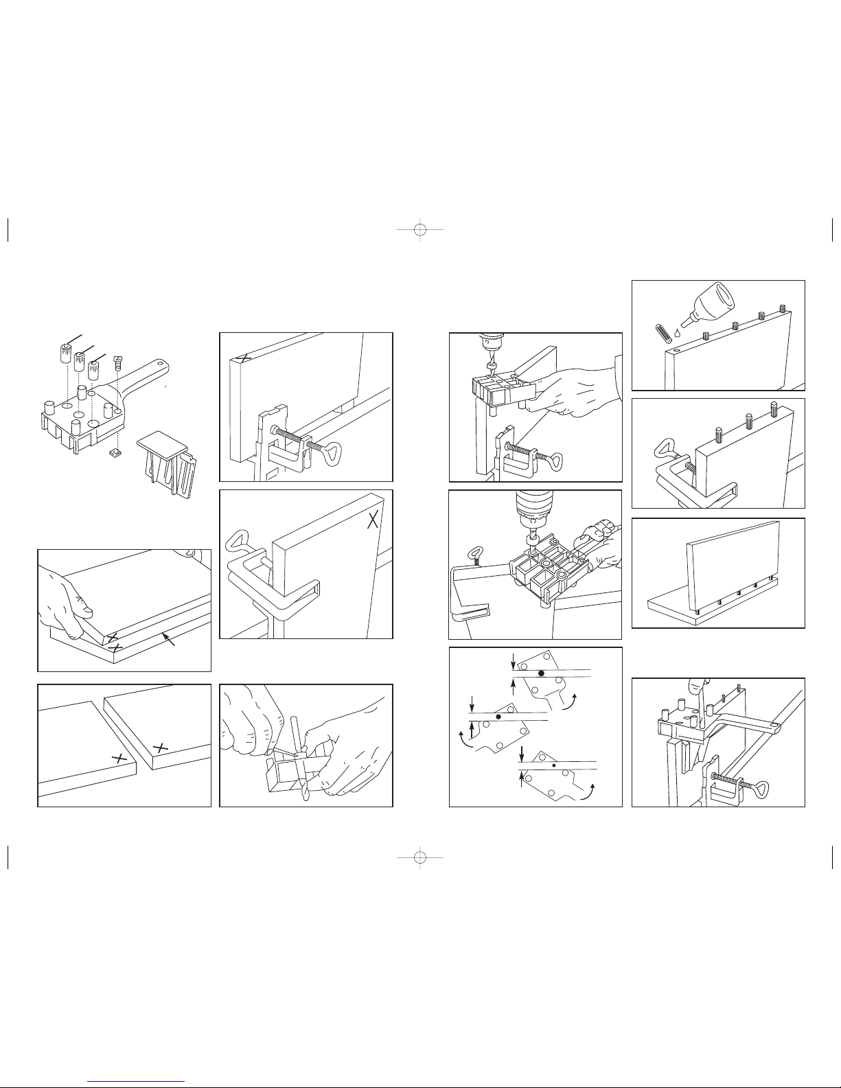
OPERATING INSTRUCTIONS
Figure 1 & 2: Mark the positions of the board in relation to
each other (X) and identify the boards with letters A & B.
Figure 3 & 4: Work On Board A for all dowel joints. Clamp
board A to the workbench.
Figure 5: Adjusting the drilling depth on board A: Dowel
Lengths (Board thickness of B 5mm). For end-grain joints
half the dowel length. Use a drill bit with a depth stop.
Figure 6, 7 & 8: Drill the holes in board A. Ensure that the
centre pin is pushed firmly against the board by pressing the
handle (see direction of arrow in Figure 8). Also ensure that
the manual dowel locator is placed level on the edge.
Important: First insert the drill bit in the drill bush and then
switch on the power drill.
Figure 12: Place the dowel locator on a dowel in board A.
Push the angle fence from the handle side into the guideway
until it rests firmly against the board. Finally tighten the
clamping screw.
6mm
Basic Dowelling Jig Operation
2
A
B
1
4
5
3
6
9
A
10
11
12
7
8
A
B
8mm
10mm
A
10mm
8mm
Max. 30mm
Max. 25mm
Max. 25mm
6mm
A
A
B
508819 Instructions.qxd 5/10/06 2:15 pm Page 2
Page 3

Figure 16 & 17: Place the board B in the desired position on
board A and clamp firmly. Draw a centre line for the dowel
holes on board B. Place the dowel locator with the side
centre marks on the centre line, push the angle fence
against board B and clamp. Then drill as shown in Figure
14.
Figure 18: T-Joint.
Figure 19 & 20: Draw a centre line for the dowel holes on
board B. Clamp board A at a distance of 35mm from the
drawn line.
Important: The depth stop must be re-adjusted (board
thickness 5mm). Now place the dowel locator with the
corresponding guiding groove over the dowel. When drilling
ensure that the centre marks are aligned with the centre line.
Figure 21: End-grain joints.
Figure 22: Place the dowel locator on a dowel in board A.
Then push the angle fence from the handle side into the
guideway until it rests firmly against the board. Finally tighten
the clamping screw.
Figure 23 & 24: Clamp board A & B in such a manner that
the marks are visible. Push the dowel locator with the
corresponding guiding groove over the dowel until the angle
fence rests firmly against the board and then drill.
Figure 13 & 14: Place board B in a desired position on
board A and clamp to the workbench.
Important: The depth stop must be re-adjusted (board
thickness 5mm). Place the dowel locator over the
corresponding dowel of board A in such a manner that the
angle fence rests firmly against the board and drill.
Figure 15: The distance of the dowel from the edge is
maximum 25mm.
13
A
B
A
A
B
B
14
25mm
35mm
16
17
18
15
B
19
22
23
24
20
21
A
B
A
B
A
B
A
B
A
A
A
B
A
508819 Instructions.qxd 5/10/06 2:15 pm Page 3
 Loading...