

Silverline 460793 Original Instructions Manual
460793
850 x 335mm
Router Table with Protractor
Router Table with Protractor
Table de défonceuse avec rapporteur
Frästisch mit Winkelmesser
www.silverlinetools.com
Mesa de fresado con
transportador de ángulos
Banco fresa con goniometro
Freestafel met gradenboog

1
5 6 7 8
3 42
9 10
16
22
11
17 18 21
23
24 25
19
20
13
1412
15
26
27 28 30 31
2
29
30
12
16
15
16
13
24
31
23
30
1
30
22
8
3
10
9
17
7
2
12
3
11
16
21
6
14
19
4
16
A B C D
27
25
29 28
5
9
10
20 82322 21
18
8
www.silverlinetools.com
3
32
33
34
35
36
37
38
39
40
4443
41
42
50
51
52
53
54
55
474849
46
56
45
4
5859
57

www.silverlinetools.com
850 x 335mm
Router Table with Protractor
English .................. 6
Français ................ 14
Deutsch ................. 22
Español ................. 30
Italiano .................. 38
Nederlands ............ 46
5

GB
Original Instructions
Introduction
Thank you for purchasing this Silverline tool. This manual contains information
necessary for safe and effective operation of this product. This product has
unique features and, even if you are familiar with similar products, it is necessary
to read this manual carefully to ensure you fully understand the instructions.
Ensure all users of the tool read and fully understand this manual.
Description of Symbols
The rating plate on your tool may show symbols. These represent important
information about the product or instructions on its use.
Wear hearing protection.
Wear eye protection.
Wear breathing protection.
Wear head protection.
Wear hand protection.
Read instruction manual.
Caution!
Conforms to relevant legislation and safety standards.
Environmental Protection
Waste electrical products should not be disposed of with household
waste. Please recycle where facilities exist. Check with your local
authority or retailer for recycling advice.
Technical Abbreviations Key
V Volts
~, AC Alternating current
A, mA Ampere, milli-Amp
Ø Diameter
° Degrees
Hz Hertz
W, kW Watt, kilowatt
Voltage range:..............................220-250V~ 50Hz
Max current:..........................................10A
Max router weight: ...................................3.5kg
Recommended router wattage:.............. 900 - 1800W (4 - 8A)
Max workpiece dimensions (L x W x H): ........2000 x 100 x 55mm
Max router base diameter: ........................155mm (6")
Max router cutter diameter: ...........................Ø32mm
Under table height to base:............................270mm
Table size (W x D):..............................450 x 335mm
Extensions (W x D):......................... 200 x 335mm (x2)
Table size with extensions (W x D): .................850 x 335mm
Bench Mounting size (W x D):.....................450 x 360mm
Protection class: ......................................
Dimensions (L x W x H): ....................865 x 375 x 390mm
Weight: .............................................7kg
Specification
As part of our ongoing product development, specifications of
Silverline products may alter without notice.
General Safety
WARNING: Read all safety warnings and all instructions. Failure to follow the
warnings and instructions may result in electric shock, fire and/or serious injury.
WARNING: This appliance is not intended for use by persons (including
children) with reduced, physical or mental capabilities or lack of experience
or knowledge unless they have been given supervision or instruction
concerning use of the appliance by a person responsible for their safety.
Children must be supervised to ensure that they do not play with the appliance.
WARNING: When using electric tools basic safety precautions should always
be followed to reduce the risk of fire, electric shock and personal injury
including the following.
Read all these instructions before attempting to operate this product and
save these instructions
Save all warnings and instructions for future reference.
The term "power tool" in the warnings refers to your mains-operated (corded)
power tool or battery-operated (cordless) power tool.
1 - Keep work area clear - Cluttered areas and benches invite injuries
2 - Consider work area environment
- Do not expose tools to rain
- Do not use tools in damp or wet locations
- Keep work area well lit
- Do not use tools in the presence of flammable liquids or gases
3 - Guard against electric shock - Avoid body contact with earthed or grounded
surfaces (e.g. pipes, radiators, ranges, refrigerators)
6

www.silverlinetools.com
Router Table with Protractor 460793
4 - Keep other persons away - Do not let persons, especially children, not
involved in the work touch the tool or the extension cord and keep them away
from the work area
5 - Store idle tools - When not in use, tools should be stored in a dry locked-up
place, out of reach of children
6 - Do not force the tool - It will perform the job better and safer at the rate for
which it was intended
7 - Use the right tool - Do not force small tools to do the job of a heavy duty tool
Do not use tools for purposes for which they are not intended; for example do
not use circular saws to cut tree limbs or logs
8 - Dress appropriately
- Do not wear loose clothing or jewellery, which can be caught in moving parts
- Suitable safety footwear is recommended when working outdoors.
- Wear protective covering to contain long hair
9 - Use protective equipment
- Use safety glasses
- Use face or dust mask if working operations create dust
WARNING: Not using protective equipment or appropriate clothing can cause
personal injury or increase the severity of an injury.
10 - Connect dust extraction equipment - If the tool is provided for the
connection of dust extraction and collecting equipment, ensure these are
connected and properly used
11 - Do not abuse the power cable - Never pull the power cable to disconnect
it from the socket. Keep the power cable away from heat, oil and sharp edges.
Damaged or entangled power cables increase the risk of electric shock
12 - Secure work - Where possible use clamps or a vice to hold the work. It is
safer than using your hands
13 - Do not overreach - Keep proper footing and balance at all times
14 - Maintain tools with care
- Keeping cutting tools sharp and clean makes the tool easier to control and
less likely to bind or lock in the workpiece
- Follow instructions for lubricating and changing accessories
- Inspect tool power cables periodically and have them repaired by an
authorised service facility if damaged
- Inspect extension cables periodically and replace if damaged
- Keep handles dry, clean and free from oil and grease
WARNING: Many accidents are caused by poorly maintained power tools.
15 - Disconnect tools - Disconnect tools from the power supply when not in
use, before servicing and when changing accessories such as blades, bits and
cutters
WARNING: The use of accessories or attachments not recommended by the
manufacturer may result in a risk of injury to persons.
16 - Remove adjusting keys and wrenches - Form the habit of checking to see
that keys and adjusting wrenches are removed from the tool before switching
it on
17 - Avoid unintentional starting - Ensure switch is in “off” position when
connecting to a mains socket, inserting a battery pack, or when picking up
or carrying the tool
WARNING: Unintended starting of a tool can cause major injuries.
18 - Use outdoor extension leads - When the tool is used outdoors, use only
extension cords intended for outdoor use and so marked. Use of an extension
cable suitable for outdoor use reduces the risk of electric shock
19 - Stay alert
- Watch what you are doing, use common sense and do not operate the tool
when you are tired
- Do not use a power tool while you are under the influence of drugs, alcohol
or medication
WARNING: A moment of inattention while operating power tools may result in
serious personal injury.
20 - Check damaged parts
- Before further use of tool, it should be carefully checked to determine that it
will operate properly and perform its intended function
- Check for alignment of moving parts, binding of moving parts, breakage of
parts, mounting and any other conditions that may affect its operation
- A guard or other part that is damaged should be properly repaired or
replaced by an authorised service centre unless otherwise indicated in this
instruction manual
- Have defective switches replaced by an authorised service centre
WARNING: Do not use the tool if the on/off switch does not switch the tool on and
off. The switch must be repaired before the tool is used.
21 - Have your tool repaired by a qualified person - This electric tool complies
with the relevant safety rules. Repairs should only be carried out by qualified
persons, otherwise this may result in considerable danger to the user
WARNING: When servicing use only identical replacement parts.
WARNING: If the power cable is damaged it must be replaced by the manufacturer
or an authorised service centre.
22 - Power tool mains plugs must match the mains socket - Never modify
the plug in any way. Do not use any adapter plugs with earthed (grounded)
power tools. Unmodified plugs and matching sockets will reduce risk of
electric shock
23 - If operating a power tool outside use a residual current device (RCD) -
Use of an RCD reduces the risk of electric shock
NOTE: The term “residual current device (RCD)” may be replaced by the term
“ground fault circuit interrupter (GFCI)” or “earth leakage circuit breaker (ELCB)”.
WARNING: When used in Australia or New Zealand, it is recommended that this
tool is ALWAYS supplied via Residual Current Device (RCD) with a rated residual
current of 30mA or less.
WARNING: Before connecting a tool to a power source (mains switch power
point receptacle, outlet, etc.) be sure that the voltage supply is the same as that
specified on the nameplate of the tool. A power source with a voltage greater than
that specified for the tool can result in serious injury to the user, and damage to the
tool. If in doubt, do not plug in the tool. Using a power source with a voltage less
than the nameplate rating is harmful to the motor.
Polarized Plugs (for North America only) To reduce the risk of electric shock, this
equipment has a polarized plug (one blade is wider than the other). This plug will fit
in a polarized outlet only one way. If the plug does not fit fully in the outlet, reverse
the plug. If it still does not fit, contact a qualified electrician to install the proper
outlet. Do not change the plug in any way.
Router Table Safety
WARNING: ALWAYS wear personal protective equipment;
• Hearing protection to reduce the risk of induced hearing loss
• Respiratory protection to reduce the risk of inhalation of harmful dust
• Cut-proof no-fray gloves to avoid possible injuries when handling router
cutters and rough material due to sharp edges. Any gloves where fabric
material can work loose with the possibility of fabric strands MUST not be
used when operating the router table
• Safety glasses to avoid eye injury caused by flying particles
• Ensure all people in the vicinity of the work area use adequate protection.
Keep bystanders a safe distance away.
WARNING: ALWAYS connect the dust extraction port on the router cutter
guard to a suitable vacuum dust extraction system. Certain types of wood
are toxic or may cause allergic reactions in people and animals, especially
when exposed to very fine dust. ALWAYS wear appropriate respiratory protection in
addition to vacuum dust extraction.
a) ONLY fit plunge routers that are listed as compatible in ‘Specification’
to the Router Table. Only fit router bits that are suitable for the installed
plunge router, with shanks compatible with the collet installed.
b) NEVER reach to the underside of the router table when the router is
connected to the power supply.
c) ALWAYS remove the router plunge spring and plastic base plate, before
fitting the tool to the router table. This enables easy router bit change and
height winder adjustment from above the table.
d) Keep your hands away from the cutting area. NEVER pass your hands
directly over, or in front of, the revolving cutter. As one hand approaches the
router bit, move it AWAY from the cutter, in an arc motion over the top of the
router bit, to the out-feed side beyond the cutter. NEVER trail your fingers
behind the workpiece and DO NOT use awkward hand positions. Use push
sticks and blocks where necessary.
e) Do not attempt to perform tasks on workpieces shorter than 300mm
(12") in length without using special fixtures or jigs. It is recommended to
make work pieces oversize then cut to finished length.
f) ASSESS risks, benefits and alternatives BEFORE using push sticks, push
blocks or other jigs and safety devices. In many applications the use of
such contraptions is useful and safe, however, in others it can be dangerous.
Push sticks can fly out of the operator’s hand, when they come into contact
with the revolving router bit, potentially causing serious injuries.
g) ALWAYS support large workpieces on the in-feed and out-feed sides of
the router table, and where necessary, also to the sides. Use an additional
stand wherever possible.
7

GB
h) ALWAYS use guards, fences, horizontal and vertical featherboards
etc., to guide the workpiece, counteract and avoid kickback, especially
when routing small or narrow workpieces. Vertical featherboards attached
to the fence also help prevent uncontrolled lift-up of the workpiece.
i) ALWAYS remove ALL loose objects from the table before operating.
Vibrations may cause loose objects to move and come into contact with the
cutter.
j) NEVER attempt to remove wood fragments or dust from the cutter with
your hands, whilst the router bit is spinning. ALWAYS switch the router off,
disconnect the machine from the power supply, and wait until the cutter has
come to a standstill. ALWAYS use cut-proof gloves when touching the cutter, to
avoid injury.
k) ALWAYS inspect the workpiece for nails, staples and other metal objects
and foreign bodies. If the router cutter hits a concealed nail, the bit may be
destroyed, high-velocity projectiles may be produced, kickback can occur, all
of which can lead to serious injury.
l) WHEREVER possible, use blind cutting techniques, where the router bit
does not protrude from underneath the workpiece. Keeping the cutter on
the underside of the workpiece provides additional operator protection.
m) ONLY expose the smallest possible part of the cutter above the table
surface. Keep any unused portion of the cutter below the table surface.
n) ALWAYS test any new setup by rotating the spindle by hand, with the
machine disconnected from the power supply. Ensure proper cutter
clearance to the throat place, fence and guard, before starting the machine.
o) ALWAYS use suitable throat plates, providing optimum clearance around
the router bit.
p) ALWAYS use the router cutter guard, and adjust the guard to cover as much
of the router bit as possible, as close to the workpiece as possible. This not
only protects the user from accessing the revolving router cutter, it also
provides effective dust extraction
q) LIMIT the depth of cut; NEVER remove too much material in one pass.
Several passes with at smaller cutting depth are safer, and produce a better
surface finish.
r) ENSURE to adjust the router cutter speed, according to router cutter
diameter and material being cut. Use the speed selection dial on the plunge
router.
s) ALWAYS feed AGAINST the rotation of the cutter. Both feed direction and
rotation are indicated by arrows on the router table surface.
t) ALWAYS use the fence if using a cutter without bearing or pilot. ALWAYS
support the workpiece firmly against the fence. NEVER remove the retractable
guards on the fence. ALWAYS use a cutter with bearing or pilot for freehand
work.
Additional safety information
• ONLY use router cutters in perfect working condition compatible with the
specification of the router table and which are suitable for hand feeding
operation (marked ‘MAN’ for manual operation according to EN 847-1)
• The bit must not enter the workpiece in the same direction as the feed
direction, which is likely to cause the workpiece to climb (climb cutting) and
may lead to loss of control during operation with the workpiece pulled away
from the operator in a hazardous way
• Do not attempt to re-sharpen router cutters unless you specifically follow the
manufacturer’s instructions and have the equipment to do so. The majority of
router cutters have blades that cannot be re-sharpened and must be replaced
immediately if dull
• Do not create fence traps caused by improper fence location. Fence traps
happen when the fence is positioned so far back that the front side of the
workpiece would be behind the router cutter. These are dangerous due to
the risk of climb cutting and the difficulty of keeping the workpiece against
the fence
• Ensure the correct table insert (table ring) is fitted that is the correct size for
the size of the router cutter fitted
• Never use a router table until fully assembled and always re-check fasteners
after re-assembly after storage
• Make certain the router is not plugged into the power outlet when installing
into the table or when making adjustments or changing accessories
• DO NOT plug the router into a standard mains wall socket. It must be
plugged into the router table switch box so can be switched off in emergency
situations
• The router table must be installed on a solid level surface and secured so the
table will not tip. Use of auxiliary in-feed and out-feed supports is necessary
for long or wide workpieces. Long workpieces without adequate support could
cause the table to tip towards the operator causing injury
• Routers create a lot of vibration and can work loose from their mountings.
Check the mountings frequently and re-tighten if necessary
• Never start the tool with the router cutter already engaged in the workpiece.
This can lead to a lack of control and possible injury
• The router table is designed to cut flat, straight and squared material only.
Do not cut material that is warped, uneven, weak or made from inconsistent
material. If necessary make sure material is correctly prepared before use.
Incorrect material can lead to a lack of control and possible injury
WARNING: Unmaintained tools can cause uncontrolled situations. ONLY use
router cutters that are correctly sharpened, maintained and adjusted in accordance
with the manufacturer’s instructions.
Note: Seek professional training and assistance before attempting work that
require procedures you are not familiar with. STOP using the router table, if, at
any point during operation, you encounter difficulties or are uncertain how to
proceed safely.
Product Familiarisation
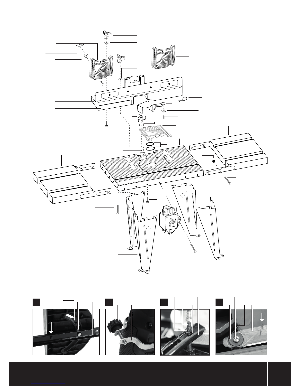
Parts List
1 Table (x 1)
2 Fence & Guard Assembly (x 1)
3 Table Extension (x 2)
4 Leg (x 4)
5 Switchbox (x 1)
6 Table Inserts (5 sizes)
7 Large Washer (x 3)
8 Small Washer (x 5)
9 Phillips Head Bolt (x 20)
10 Nut (x 24)
11 Featherboard Pad (x 2)
12 Knob (x 3)
13 Featherboard Coach Bolt (x 4)
14 Fence Bolt (x 2)
15 Featherboard Wing Nut (x 4)
16 Large Washer (x 7)
17 Fence Knobs (x 2)
18 Router Securing Bar (x 4)
19 Bolt (x 2)
20 Router Securing Bolts (x 4)
21 Guard (x 1)
22 Guard Spring (x 1)
23 Guard Screw (x 1)
24 Adjustable Fence (x 1)
25 Protractor Guide Bar (x 1)
26 Protractor Body (x 1)
27 Protractor Knob (x 1)
28 Router Trigger Clamp (x 1)
29 Router Trigger Clamp Knob (x 1)
30 Featherboard (x 3)
31 Short Bolt (x 1)
8

www.silverlinetools.com
Router Table with Protractor 460793
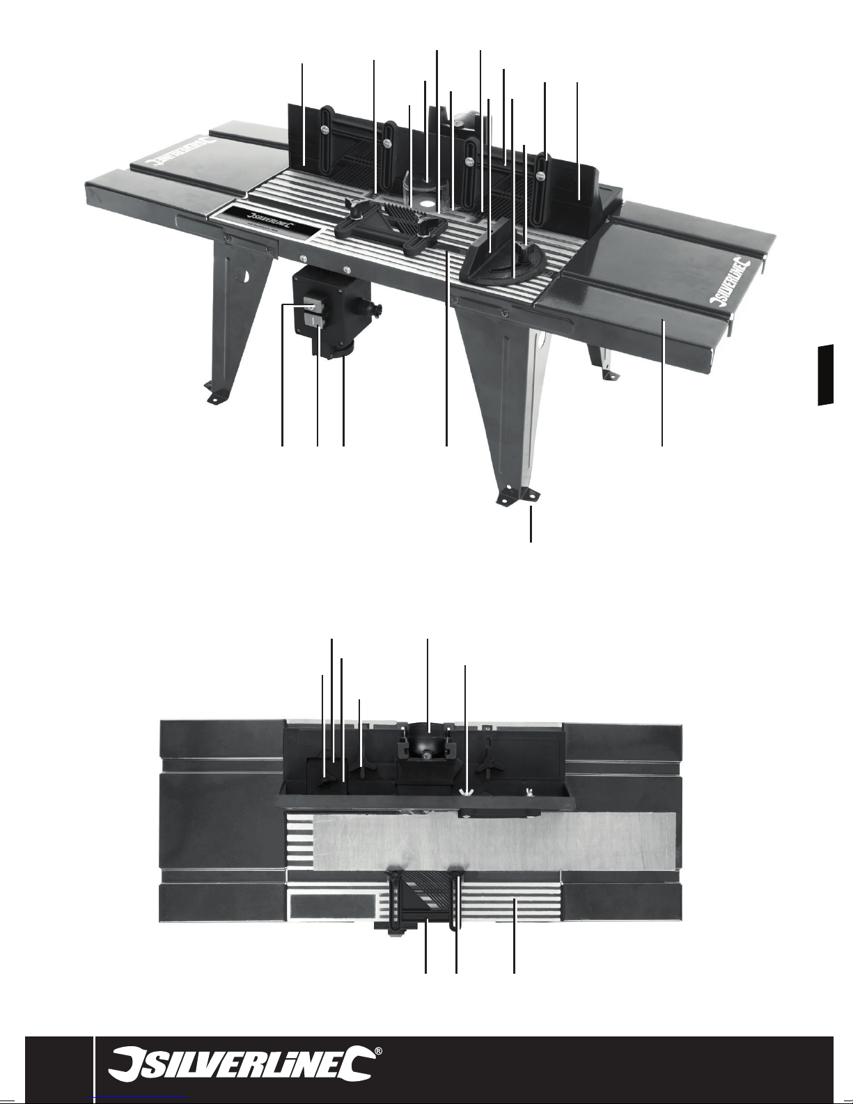
Assembled
32 Adjustable Fence
33 Table Scale
34 Direction Indicator
35 Guard
36 Table Insert Mounting
37 Guard Moving Point
38 Feathers
39 Protractor
40 Featherboard Direction Indicator
41 Protractor Angle Scale
42 Protractor Knob
43 Vertical Featherboard
44 Main Fence
45 Protractor Channel
46 Bench Mounting Holes
47 Horizontal Featherboard Mounting
48 Mains Socket
49 On Button
50 Off Button
51 Adjustable Fence Knob
52 Adjustable Fence Scale
53 Adjustable Fence Indicator
54 Main Fence Knob
55 Dust Extraction Port
56 Vertical Featherboard Wingnut
57 Main Table
58 Horizontal Featherboard Knob
59 Horizontal Featherboard
Intended Use
Router table for temporary or permanent bench mounting or alternatively fitting
to a dedicated tool stand. Capable of edge rebating, trenching, cross trenching,
planing, edge moulding (fence and freehand), end grain work, jointing, using a
template guide, and morticing. For use with the routers from 900W to 1800W
power with a circular or semi-circular base with a diameter 155mm or less.
Unpacking Your Tool
• Carefully unpack and inspect your tool. Fully familiarise yourself with all its
features and functions
• Ensure that all parts of the tool are present and in good condition. If any
parts are missing or damaged, have such parts replaced before attempting
to use this tool
Before Use
WARNING: Ensure the tool is disconnected from the power supply before
attaching or changing any accessories, or making any adjustments.
Assembling the router table
See the exploded diagram at the beginning of the manual for a general quick view
of how the table fits together then follow the instructions below.
Table
1. Place the Table (1) upside down on a flat surface that will not scratch or
damage the parts or allow the parts to move
2. Line up the Table Extensions (3) ready for attachment on both ends of the
Table
3. Fit one Leg (4) into the recess of the Table and insert a Phillips Head Bolt (9)
through the Table Extension, through the Table and finally through a mounting
hole of the Leg. Fit a Nut (10) onto the thread of the bolt and tighten loosely
Note: The Legs fit inside the underneath of the Table whereas the Table Extensions
are mounted on the external sides of the Table.
4. Repeat until the Leg is secured for that corner and then repeat for all Legs
until the main Table, Table Extensions and Legs are all fitted. Tighten so the
Legs and Table Extensions can still be moved by hand but hold the position
they are left in. This allows for adjustment before final tightening
5. Check the flat surface you are using is level with a spirit level for both axes.
Turn the router table over and check all the bench-mounting feet are level and
flat on the surface. Use a spirit level to check the Table and Table Extensions
are level on both axes and adjust the position of the Legs and Table Extensions
if necessary
6. Once level carefully tighten the Nuts to lock that position. Do not over-tighten.
Make sure the router table remains level after tightening and does not rock
7. Attach the Switchbox (5) to the underside front of the Table using two Phillips
Head Bolts (9) and two Nuts (10)
8. Fit the Horizontal Featherboard using one of the Featherboards (30), both
Featherboard Pads (11), two Knobs (12) and both Fence Bolts (14). The pads
should be placed into the channel of the Table with the raised edges of the
pads placed to the left and right side of the Featherboard
IMPORTANT: Note the direction of the Featherboard feathers in the main image of
the Router Table. It is important that both vertical and the horizontal Featherboards
are facing the correct way to work with the feed direction as shown.
Mounting the router
IMPORTANT: If the router is earthed the Switchbox (5) and any mains
extensions used must be earthed and connected to an earthed power point.
1. Please refer to the specification and check the router you intend to use is
compatible
2. Have your original router manual to hand and read before mounting. Make
sure mounting won’t restrict changing bits. Check that you still have easy
access to the spindle lock button, adjusting router height and the collet
securing nut
3. Ensure the base of the router is completely clean so it will be level with the
mounting plate when fitted
4. If the Router doesn’t feature a trigger lock-on feature, use the Router Trigger
Clamp (28) and Router Trigger Clamp Knob (29) to lock the trigger in the on
mode (Image B) or lock the trigger on
5. Insert the four Router Securing Bolts (20) through the Table (1) surface and on
the underside fit a Router Securing Bar (18), Small Washer (8) and Nut (10) to
each bolt. Only loosely fit together at this stage
6. Turn the Table (1) upside down making sure each Router Securing Bolt is
still locked in the recess of the Table to prevent turning and move the Router
Securing Bars so they face away from the centre to allow fitting of the router
7. Carefully lower the router into the central recess of the Table ensuring the
router is centred so the bit is dead centre in the Table opening. This is critical
so take time to get this right
8. Use the Router Securing Bars to secure the base of the router to the underside
of the Table (Image C) then tighten all Nuts. Router bases vary in design and
you will need to adapt to the shape of the base. Check the base is securely
gripped and the Router Securing Bar are not blocking any feature of the base,
for example the router’s own dust extraction fittings
Note: Once you start using the router table, remember to recheck these fittings
after a short amount of use to make sure they have not loosened. Then make
it a regular check in the future. If the router drops from its mountings it may be
damaged or destroyed.
9

GB
9. Recheck the router is correctly centralised and that you are happy with its
position for access to all its features
10. Finally connect the power cable of the router to the Mains Socket (48) but
make sure at this point the Switchbox is not connected to a mains supply
Fence & Guard
1. Attach the Adjustable Fence (24) to the Fence & Guard Assembly (2) using a
Knob (12), Large Washer (16) and Short Bolt (31)
2. Attach the Guard (21) to the Fence & Guard Assembly using Guard Screw
(23), Small Washer (8) and the Guard Spring (22). See image D for how the
spring attaches. Take time to make sure the Guard moves smoothly as it is an
important safety feature
3. Attach 2 of the Featherboards (30) to the Fence & Guard Assembly to be used
as vertical Featherboards using Featherboard Coach Bolts (13), Large Washers
(16) and Featherboard Wing Nuts (15)
4. Attach the assembled Fence & Guard Assembly to the Table using two Bolts
(19), Large Washers (7) and Fence Knobs (17). Use the two Table Scales (33)
to mount in a level position
Bench mounting
It is important the Router Table is securely mounted especially when working with
long workpieces. The Router Table can be secured to a workbench or a dedicated
work stand. Alternatively the table can be attached to a piece of wood which can
then be clamped to another work surface when needed which allows for easy
removal. It is not designed to be used without being attached to another surface.
• Use screws or bolts (not supplied) through the Bench Mounting Holes (46) to
secure the Table (1)
Assembling the Protractor
• Assemble the Protractor using the Protractor Body (26), Protractor Guide Bar
(25), Protractor Knob (27) and a Large Washer (16). The guide bar fits over the
pin (arrowed in Image A) and the Protractor Knob secures the assembly
Connecting dust extraction
IMPORTANT: Dust from certain materials and surface coatings can be toxic. Use a
dust extraction system or vacuum whenever possible.
• If possible create a dual extraction system using both the Dust Extraction Port
(55) of the Table for extraction above the Table and use the dust extraction
port of your router which will operate below the Table. This is the ideal solution
however using just the Dust Extraction Port (55) of the router table will be
sufficient. When using just the table’s own dust extraction port the correct
size of Table Insert becomes more important which will keep more dust and
chippings on top for easy extraction
• In the absence of dust extraction work for short periods only and clean the
table frequently. This is not recommended
Configuring the router
For setting up your router refer to your router manual. Once setup fit the correct
size Table Insert (6) to match the size of router bit fitted. Place over the router bit
and turn to lock in position. Ensure there is a small gap around the edge of the
router bit blade so the blade and Table Insert can never touch either in use or when
changing bits
User position and feed direction
• The main user position is defined by the location of the Switchbox (5)
• ALWAYS remain positioned in close proximity to the switch, so the machine
can be instantly switched off in the case of emergency
• Feed workpieces from this position in the direction indicated by the arrows
on the table which is feed from the right side of the table (input) to the left
side (output)
Using the router table
As with most woodworking accurate measurement and pre-cut setup is critical to
getting the right results. This manual is only a basic guide to operation. For best
results seek further training or reading material. It is recommended to use scrap
material while getting used to operating this table.
• Wear eye protection
• Check router fittings and collet nut is tight before use
• Feed workpiece against rotation of cutter. Feed direction is shown by on
the fence and featherboards
• With your hands not awkwardly positioned hold the workpiece securely
• Keep fingers away from the revolving cutter. Use the featherboards when
possible
• Both the Vertical Featherboards (43) and Horizontal Featherboard (59) are
used to apply light pressure to the workpiece to hold it more securely as it
is cut. To adjust the height of the Vertical Featherboards loosen the Vertical
Featherboard Wingnuts (56) and reposition the height then retighten. For
the Horizontal Featherboard loosen the Horizontal Featherboard Knob (58)
adjust and re-tighten
• Use the Protractor (39) fitted to the Protractor Channel (45) to present angled
workpieces to the cutting point. To adjust the Protractor angle loosen the
Protractor Knob (42) and use the Protractor Angle Scale (41). Remove the
Horizontal Featherboard if necessary
• For some cuts the Adjustable Fence (32) is used. This allows workpieces
which have been cut into a shorter width to be supported after the cut. This
is an often used function especially for making joints. To alter the Adjustable
Fence position, loosen the Adjustable Fence Knob (51) and adjust the position
using the Adjustable Fence Scale (52) and Adjustable Fence Indicator (53).
Typical use would be to make a small first cut with scrap material and then
align the Adjustable Fence with the scrap wood before then making the
required cut on another workpiece
• To alter the Main Fence (44) position loosen the two Main Fence Knobs (54)
and adjust its position using the Table Scales (33) then retighten the Main
Fence Knobs
• Other adjustments are made using your router including cutter height. Refer
to your router manual
Accessories
• A wide range of accessories for this tool, including a Machine Tool Stand
(126657), Roller Stands (675120), Push Stick (675346), PPE equipment and
router bits, is available from your Silverline stockist. Replacement parts are
available from your Silverline stockist or www.toolsparesonline.com
Operation
WARNING: ALWAYS wear eye protection, adequate respiratory and hearing
protection, as well as suitable non-fabric gloves, when working with this tool.
Switchbox operation
IMPORTANT: The switchbox requires a live mains connection to switch ON. It will
reset to OFF as soon as power is disconnected and require resetting to ON when
power is restored to continue operation.
Switching on and off
The Switchbox (5) controls power to the router bypassing the normal router on/off
button which is set permanently on.
1. Connect the Switchbox lead to a wall socket and switch on
2. Switch the router on by pressing the On Button (49) ‘I’
3. Switch off the router by pressing the Off Button (50) ‘O’
10
Maintenance
WARNING: ALWAYS disconnect from the power supply before carrying out any
inspection, maintenance or cleaning.
General inspection
• Regularly check that all the fixing screws are tight
• Inspect the supply cord of the tool, prior to each use, for damage or wear.
Repairs should be carried out by an authorised Silverline service centre. This
advice also applies to extension cords used with this tool
Cleaning
• Keep your tool clean at all times.
• Clean the tool casing with a soft damp cloth using a mild detergent. Do not
use alcohol, petrol or strong cleaning agents
• Never use caustic agents to clean plastic parts
Other maintenance
• If cleaning does not return correct operation use dry or thin lubricants to keep
the tool in good operation. Ensure the guard is always working correctly,
lubricate if necessary
• Where paint has been worn off, repaint those small areas to prevent corrosion

www.silverlinetools.com
Router Table with Protractor 460793
Storage
• Store this tool carefully in a secure, dry place out of the reach of children
Disposal
Always adhere to national regulations when disposing of power tools that are no
longer functional and are not viable for repair.
• Do not dispose of power tools, or other waste electrical and electronic
equipment (WEEE), with household waste
• Contact your local waste disposal authority for information on the correct way
to dispose of power tools
11

GB
Troubleshooting
Problem Possible cause Solution
No power Check the Switchbox (5) is connected to a live mains connection
Router mains plug not connected to Switchbox socket Connect router mains plug to Switchbox
Router will not operate
Router runs or cuts slowly
Excessive vibration
Router on/off switch not on or Router Trigger Clamp
not fitted
Router incorrectly setup Follow information in router manual
Router faulty Get router repaired or replace
Switchbox will not stay on Wattage of router too high. See Specification
Router incorrectly set up See router manual
Wattage of router is too low for use with router table See Specification
Router incorrectly mounted Secure router to table correctly
Router table not bench mounted or not secured to
surface with clamps
Router too powerful for table See Specification and fit a compatible router to table
Ensure router on/off switch is locked or clamped in on position
Secure router table correctly. See ‘Bench Mounting’
12

www.silverlinetools.com
Router Table with Protractor 460793
Silverline Tools Guarantee
This Silverline product comes with a 3 year guarantee
Register this product at www.silverlinetools.com within 30 days of purchase in order
to qualify for the 3 year guarantee. Guarantee period begins according to the date of
purchase on your sales receipt.
Terms & Conditions
Guarantee period becomes effective from the date of retail purchase as detailed on
your sales receipt.
PLEASE KEEP YOUR SALES RECEIPT
If this product develops a fault within 30 days of purchase, return it to the stockist
where it was purchased, with your receipt, stating details of the fault. You will
receive a replacement or refund.
If this product develops a fault after the 30 day period, return it to:
Silverline Tools Service Centre
PO Box 2988
Yeovil
BA21 1WU, UK
The guarantee claim must be submitted during the guarantee period.
You must provide the original sales receipt indicating the purchase date, your name,
address and place of purchase before any work can be
carried out.
You must provide precise details of the fault requiring correction.
Claims made within the guarantee period will be verified by Silverline Tools to
establish if the deficiencies are related to material or manufacturing of the product.
Carriage will not be refunded. Items for return must be in a suitably clean and safe
state for repair, and should be packaged carefully to prevent damage or injury
during transportation. We may reject unsuitable or
unsafe deliveries.
All work will be carried out by Silverline Tools or its authorized
repair agents.
The repair or replacement of the product will not extend the period
of guarantee
Defects recognised by us as being covered by the guarantee shall be corrected
by means of repair of the tool, free of charge (excluding carriage charges) or by
replacement with a tool in perfect working order.
Retained tools, or parts, for which a replacement has been issued, will become the
property of Silverline Tools.
Registering your purchase
Registration is made at silverlinetools.com by selecting the Guarantee Registration
button. You will need to enter:-
• Your personal details
• Details of the product and purchase information
Once this information is entered your guarantee certificate will be created in PDF
format for you to print out and keep with your purchase.
The repair or replacement of your product under guarantee provides benefits which
are additional to and do not affect your statutory rights as a consumer.
What is covered:
The repair of the product, if it can be verified to the satisfaction of Silverline Tools
that the deficiencies were due to faulty materials or workmanship within the
guarantee period.
If any part is no longer available or out of manufacture, Silverline Tools will replace it
with a functional replacement part.
Use of this product in the EU.
What is not covered:
Silverline Tools does not guarantee repairs required as a result of:
Normal wear and tear caused by use in accordance with the operating instructions
eg blades, brushes, belts, bulbs, batteries etc.
The replacement of any provided accessories drill bits, blades, sanding sheets,
cutting discs and other related items.
Accidental damage, faults caused by negligent use or care, misuse, neglect,
careless operation or handling of the product.
Use of the product for anything other than normal domestic purposes.
Change or modification of the product in any way.
Use of parts and accessories which are not genuine Silverline Tools components.
Faulty installation (except installed by Silverline Tools).
Repairs or alterations carried out by parties other than Silverline Tools or its
authorized repair agents.
Claims other than the right to correction of faults on the tool named in these
guarantee conditions are not covered by the guarantee.
Battery Guarantee
Silverline batteries are guaranteed for 30 days. If a defect occurs on a registered
battery during the term of the Battery Guarantee, due to material or manufacturing
fault, then Silverline will replace it free of charge. This guarantee does not apply to
commercial use nor does it extend to normal wear and tear or damage as a result of
accident, abuse or misuse.
13

FR
Traduction des instructions originales
Introduction
Nous vous remercions d’avoir choisi cet équipement Silverline. Ces instructions
contiennent les informations nécessaires pour vous en garantir un fonctionnement
efficace et en toute sécurité. Veuillez lire attentivement ce manuel pour vous
assurer de tirer pleinement avantage des caractéristiques uniques de votre nouvel
équipement.
Gardez ce manuel à portée de main et assurez-vous que tous les utilisateurs
l’aient lu et bien compris avant toute utilisation. Conservez-le pour toute référence
ultérieure.
Description des symboles
La plaque signalétique figurant sur votre outil peut présenter des symboles. Ces
symboles constituent des informations importantes relatives au produit ou des
instructions concernant son utilisation.
Port de protection auditive
Port de lunettes de sécurité
Port de masque respiratoire
Port de casque
Port de gants
Lire le manuel d’instructions
Attention !
Conforme à la réglementation et aux normes de sécurité pertinentes.
Protection de l’environnement
Les produits électriques usagés ne doivent pas être jetés avec les
ordures ménagères. Veuillez les recycler dans les centres prévus à
cet effet. Pour de plus amples informations, veuillez contacter votre
municipalité ou point de vente.
Abréviations pour les termes techniques
V Volts
~, AC Courant alternatif
A, mA Ampère, Milliampère
Ø Diamètre
° Degrés
Hz Hertz
W, kW Watt, kilowatt
Caractéristiques techniques
Plage de tension : ..........................220-250 V~ 50 Hz
Courant max : ........................................10 A
Poids de défonceuse max supporté : .....................3,5 kg
Puissance de défonceuse recommandée : ... 900 – 1 800 W (4 – 8 A)
Dimensions max de la pièce
d’ouvrage (L x l x H) : .....................2 000 x 100 x 55 mm
Diamètre max d’embase de défonceuse :................155 mm
Diamètre de fraise max :.............................Ø 32 mm
Hauteur sous la table à l’embase : .....................270 mm
Dimensions de la table (l x P) : ...................450 x 335 mm
Rallonges (l x P) : ......................... 200 x 335 mm (x 2)
Dimensions de la table avec rallonges (l x P) : .......850 x 335 mm
Dimensions de l’assemblage de l’établi (l x P) : ......450 x 360 mm
Classe de protection : ..................................
Dimensions (L x l x H) : ....................865 x 375 x 390 mm
Poids :.............................................. 7 kg
Du fait de l’évolution constante de nos produits, les caractéristiques des
produits Silverline peuvent changer sans notification préalable.
14
Consignes de sécurité générales
relatives à l’utilisation d’appareils
électriques
AVERTISSEMENT : Veuillez lire toutes les consignes de sécurité et toutes
les instructions. Le non-respect des instructions et consignes de sécurité peut
entraîner un risque de décharge électrique, d’incendie et/ou se traduire par des
blessures graves.
AVERTISSEMENT : Cet appareil n’est pas prévu pour être utilisé par des
personnes (enfants y compris) ayant des capacités mentales ou physiques
réduites ou manquant d’expérience à moins qu’ils soient supervisés ou
qu’une personne responsable de leur sécurité leur donne des instructions
concernant l’utilisation de cet appareil.
AVERTISSEMENT : Lorsqu’un appareil électrique est utilisé, des mesures de
sécurité élémentaires doivent toujours être observées afin de réduire tout
risque d’incendie, de choc électrique ou de blessures corporelles, dont celles
énoncées ci-après. Lisez ces consignes de sécurité et la totalité du présent
manuel d’instructions avant d’entreprendre d’utiliser votre appareil.
Veuillez conserver ces instructions et consignes de sécurité pour référence
ultérieure.
L’expression « appareil/outil électrique » employée dans les présentes consignes
recouvre aussi bien les appareils filaires à brancher sur secteur que les appareils
sans fils fonctionnant avec batterie.

www.silverlinetools.com
Table de défonceuse avec rapporteur460793
1. Maintenir une zone de travail propre. Des zones encombrées et mal
éclairées sont sources d’accidents.
2. Prendre en compte la zone de travail :
- Ne pas exposer les outils à la pluie,
- Ne pas utiliser les outils dans des endroits humides,
- Travailler dans une zone bien éclairée,
- Ne pas utiliser d’outils électriques dans des environnements explosifs, tels
qu’à proximité de liquides, de gaz ou de poussières inflammables.
3. Éviter les décharges électriques : Éviter le contact corporel avec les surfaces
mises à la terre telles que tuyaux, radiateurs, cuisinières et réfrigérateurs.
4. Éloigner les personnes aux alentours. Ne laisser aucune personne dont
la présence n’est pas nécessaire, surtout les enfants, s’approcher de la zone
de travail et d’être en contact avec l’appareil.
5. Ranger les appareils électriques inutilisés dans un endroit sûr, sec et hors
de portée des enfants.
6. Ne pas forcer sur l’appareil électrique. Un appareil électrique adapté et
employé au rythme pour lequel il a été conçu permettra de réaliser un travail
de meilleure qualité et dans de meilleures conditions de sécurité
7. Utiliser l’appareil électrique approprié au travail à effectuer. Ne pas
utiliser de petits outils pour de tâches lourdes. N’utilisez pas l’outil pour une
tâche pour laquelle il n’a pas été prévu.
8. Porter des vêtements appropriés.
- Ne pas porter de vêtements amples ou des bijoux pendants qui peuvent être
happés par les pièces en rotation.
- Le port de chaussures antidérapantes est recommandé en extérieur.
- Attacher ou protéger les cheveux longs.
9. Porter un équipement de protection approprié.
- Porter une protection oculaire.
- Porter un masque à poussières lors de travaux créant de la poussière.
ATTENTION : Ne pas porter d’équipements de protection ou de vêtements
appropriés peut engendrer et aggraver des blessures.
10. Brancher un système d’extraction de la poussière : si l’appareil est pourvu
de dispositifs destinés au raccord d’équipements d’extraction et de
récupération de la poussière/sciure, s’assurer qu’ils soient bien fixés et utilisés
correctement.
11. Ne pas maltraiter le cordon électrique. Ne jamais utiliser le cordon
électrique pour porter, tirer ou débrancher l’appareil. Protéger le cordon
électrique de la chaleur, du contact avec l’essence, des bords tranchants et
pièces rotatives. Un cordon électrique endommagé ou entortillé accroît le
risque de décharge électrique.
12. Immobiliser votre travail. Si possible, utiliser des serre-joints ou un étau pour
maintenir la pièce de travail. C’est plus sûr et efficace que de tenir avec la
main.
13. Ne pas essayer d’atteindre une zone hors de portée. Se tenir toujours en
position stable permettant de conserver l’équilibre.
14. Veiller à l’entretien des appareils électriques.
- Veiller à ce que les outils de coupe soient tenus affûtés et propres.
- Suivre les instructions de lubrification et de changement des accessoires.
- Vérifier régulièrement les câbles et les faire réparer /remplacer par un centre
agrée.
- Vérifier également l’état des rallonges utilisées.
- Travailler avec des mains propres (sans graisse ni huile) et sèches.
ATTENTION : de nombreux accidents sont dus à l’utilisation d’appareils électriques
mal entretenus
15. Débrancher l’appareil électrique. Lorsque l’appareil n’est pas utilisé,
ou avant tout opération d’entretien ou de changement d’accessoires, veiller à
débrancher l’appareil de sa source d’alimentation.
ATTENTION : utiliser des accessoires non recommandés par le fabricant peut
engendrer des blessures.
16. Enlever les clés et outils de réglage. Prendre l’habitude de retirer ces outils
avant de mettre l’appareil en marche.
17. Éviter tout démarrage accidentel ou intempestif. S’assurer que
l’interrupteur marche-arrêt soit en position d’arrêt avant de brancher l’appareil
sur l’alimentation secteur ou d’installer la batterie, de prendre l’appareil ou de
le transporter.
ATTENTION : des démarrages accidentels peuvent être dangereux.
18. Usage en extérieur : Lors d’une utilisation de l’appareil électrique en extérieur,
se servir d’une rallonge appropriée à une utilisation en extérieur. Cela réduit le
risque de décharge électrique.
19. Rester vigilant.
- Faire preuve de bon sens lors de la manipulation de l’appareil.
- Ne pas utiliser un appareil électrique lorsque l’on se trouve dans un état de
fatigue, ou sous l’influence de drogues, d’alcool ou de médicaments.
ATTENTION : un moment d’inattention pendant l’utilisation d’un outil électrique
peut se traduire par des blessures graves.
20. Inspecter les pièces endommagées
- Avant d’utiliser un appareil, toujours vérifier qu’il soit en bon état de marche.
- Vérifier que les éléments rotatifs soient bien alignés et non grippés. S’assurer
de l’absence de pièces cassées ou endommagées susceptibles de nuire au
bon fonctionnement de l'appareil.
- Une protection ou partie défectueuse doit être réparée ou remplacée par un
centre agrée, sauf en cas d’indication du manuel.
- Les interrupteurs défectueux doivent être remplacés par un centre agrée.
ATTENTION : ne pas utiliser un appareil électrique dont la commande ne s’effectue
plus par l’interrupteur marche-arrêt. Il est dangereux et doit être réparé.
21. Ne faire réparer votre appareil électrique que par un réparateur qualifié.
Cet appareil est conforme aux normes de sécurité en vigueur. Cela permet
de maintenir la sécurité d’utilisation de l’appareil électrique et d’éviter des
risques considérables pour l’utilisateur.
ATTENTION : utiliser uniquement des pièces de rechange identiques.
ATTENTION : si le câble d’alimentation est endommagé, le faire remplacer par un
centre agrée.
22. La prise d’un appareil électrique doit être adaptée à la prise du secteur.
Ne jamais modifier la prise en aucune façon. Ne jamais utiliser d’adaptateur
sur la prise électrique d’appareil mis à la terre. Des prises non modifiées,
adaptées aux boîtiers de prise de courant, réduiront le risque de décharge
électrique.
23. Si une utilisation de l’appareil électrique dans un environnement humide
ne peut être évitée, utiliser une alimentation protégée par un disjoncteur
différentiel. L’utilisation d’un disjoncteur différentiel réduit le risque de
décharge électrique.
ATTENTION : Lorsque utilisé en Australie ou en Nouvelle Zélande, il est
recommandé que cet appareil soit toujours alimenté via un disjoncteur différentiel
ayant un courant résiduel de 30 mA ou moins.
AVERTISSEMENT : Avant de brancher un appareil sur une source d’alimentation
(prise secteur, groupe électrogène, etc.) assurez-vous que la tension fournie soit
la même que celle spécifiée sur la plaque de l’appareil. Une source d’alimentation
avec une tension supérieure à celle indiquée sur l’appareil peut engendrer de
sérieuses blessures pour l’utilisateur et endommager l’appareil. En cas de doute,
ne branchez pas l’appareil. Une source d’alimentation avec une tension inférieure
à celle indiquée sur l’appareil est néfaste pour le moteur.
Prises polarisées (uniquement pour les pays de l’Amérique du Nord). Afin de
réduire le risque de choc électrique, cet appareil comporte une prise polarisée
(une des fiches est plus large que l’autre). Cette prise se branche dans une
prise de courant polarisée uniquement dans un sens. Si la prise ne rentre pas
complètement, inverser la prise. Si vous ne parvenez toujours pas à la faire rentrer,
contacter un électricien qualifié pour installer une prise de courant adaptée. Ne
modifiez la prise de l’appareil en aucune façon.
Consignes de sécurité relatives à
l’utilisation d’une table pour défonceuse
ATTENTION : Portez TOUJOURS une équipement personnel de protection :
• Une protection auditive afin de réduire les risques de perte auditive
• Une protection respiratoire afin de réduire les risques d’inhalation de poussière
toxique
• Des gants anti-coupures afin d’éviter les blessures lors du maniement des
fraises de coupe et des matériaux bruts aux bords coupants. Les gants en
tissu amples ou effilochés ne DOIVENT pas être utilisés lors de l’utilisation de
la table pour défonceuse.
• Des protections oculaires afin d’éviter des blessures dues aux particules.
Assurez-vous que les personnes présentent sur la zone de travail portent des
protections adaptées. Maintenez toute autre personne à distance.
ATTENTION : Branchez TOUJOURS le port d’extraction de la poussière sur
un système d’aspiration adapté. Certaines poussières de bois sont toxiques
ou peuvent causer des réactions allergiques chez les animaux et les humains,
surtout lors de l’exposition à des poussières fines. Portez toujours des protections
respiratoires adaptées en plus d’un système d’aspiration.
15

FR
a) N’installez QUE des défonceuses listées comme étant compatibles dans
les « Caractéristiques techniques ». N’installez que des défonceuses
adaptées pour des coupes plongeantes, avec une tige compatible et une pince
de serrage installée.
b) Ne vous approchez pas du dessous de la table lorsque la défonceuse est
branchée sur une alimentation.
c) Démontez TOUJOURS le ressort de plongée et le plateau de la base en
plastique, avant de l’installez sur la table de la défonceuse. Cela permet
de changer les fraises et le d’utiliser le remontoir depuis le dessus de la table.
d) Gardez vos mains hors de portée des lames. N’approchez pas vos mains
de la fraise en mouvement. Lorsqu’une main s’approche de la fraise, éloignez la de la fraise dans un mouvement de demi-cercle au-dessus de la fraise vers
la sortie de l’autre côté. Ne gardez pas vos doigts derrière la pièce à travailler.
Ne mettez pas vos mains dans une position inhabituelle. Utilisez un bâton ou
un bloc poussoir lorsque cela est nécessaire.
e) Ne défoncez jamais de bois plus court que 300 mm (12") sans utiliser
d’outils spécialisés ou un gabarit. Effectuez des coupes sur des pièces
longues puis coupez-les à la longueur voulue.
f) Évaluez les risques, les avantages et les alternatives AVANT d’utiliser un
bâton ou un bloc poussoir ou tout autre gabarit et équipement de
sécurité. Dans de nombreux cas, l’utilisation de ces outils est utile et sûre,
cependant cela peut parfois être dangereux. Les bâtons poussoir peuvent être
éjectés des mains de l’opérateur lorsqu’ils rentrent en contact avec la fraise
en rotation et potentiellement causer des blessures.
g) Supportez TOUJOURS les pièces à travailler de grandes tailles et la sortie
de la table de la défonceuse, et lorsque cela nécessaire, supportez aussi
les côtés. Utilisez des supports Triton à rouleaux ou des tréteaux lorsque cela
est possible.
h) Utilisez TOUJOURS les gardes, guides et peignes horizontaux et verticaux
etc. pour guider la pièce à travailler, évitez contrecarrez l’effet de rebond,
surtout lors des coupes sur des pièces de petites taille ou étroite. Les
peignes verticaux fixés sur le guide participe à la prévention de l’effet de
rebond et de la montée incontrôlée de la pièce.
i) Avant utilisation, enlevez TOUJOURS tous objets laissés sur la table. Les
vibrations peuvent entraîner un mouvement des objets laissés sur la table et
les entraîner vers la fraise.
j) N’essayez JAMAIS d’enlever des fragments, des poussières de la fraise
à la main, lorsque la fraise est en rotation. Éteignez toujours la défonceuse,
débranchez la machine de son alimentation et attendez que la fraise soit à
l’arrêt. Portez TOUJOURS des gants anti-coupures lorsque vous touchez la
fraise.
k) Vérifiez TOUJOURS qu’il n’y a ni clous, ni agrafes ou tout autre objet
métallique ou corps étranger. Si la fraise heurte un clou caché, la fraise peut
se briser, des projectiles très rapides peuvent être produits, un effet de rebond,
le tout pouvant occasionner des blessures sérieuses.
l) Lorsque cela est possible, utilisez une technique de coupe à l’aveugle où
la fraise ne dépasse pas de la pièce à travailler. Garder la fraise sous la
pièce offre une protection supplémentaire à l’opérateur.
m) Ne laissez dépasser QU’une partie la plus petite possible de la fraise.
Gardez la partie inutilisée de la fraise sous la surface de la table.
n) Testez TOUJOURS une nouvelle installation en tournant l’arbre à main
avec la machine débranchée de sa source d’alimentation. Assurez-vous
que le dégagement au niveau de la plaque à gorge avant de démarrer la
machine.
o) Utilisez TOUJOURS une plaque à gorge adaptée, qui offre le dégagement
nécessaire autour de la fraise.
p) Utilisez TOUJOURS la garde de la fraise, réglez la garde au plus près
possible de la fraise et de la pièce à travailler. Cela permet une bonne
protection de l’utilisateur est une bonne extraction de la poussière.
q) LIMITEZ la profondeur de coupe ; n’enlevez JAMAIS trop de matière
en une passe. Une coupe en plusieurs passes permet un travail plus sûr et de
meilleure qualité.
r) ASSUREZ-vous que la vitesse de la défonceuse correspond à la vitesse
et au diamètre de la fraise ainsi qu’au matériau coupé. Utilisez le réglage
de la vitesse de la défonceuse.
s) Alimentez TOUJOURS la pièce dans le sens contraire du sens de rotation
de la fraise. Le sens de rotation de la fraise et la direction d’alimentation sont
indiqués par des flèches sur la surface de la table.
t) Utilisez TOUJOURS le guide lors de l’utilisation d’une fraise sans
roulement ou pilote. Supportez TOUJOURS la pièce fermement contre le
guide. N’enlevez JAMAIS les gardes rétractables du guide. Utilisez TOUJOURS
une fraise avec un roulement ou un pilote lors d’une utilisation à main levée.
Consignes de sécurité supplémentaires
• N’utilisez QUE des fraises en parfait état de marche compatibles avec les
caractéristiques de la table de la défonceuse et compatibles avec une
utilisation à main levée (marqué MAN pour les opérations manuelles selon
EN 847-1)
• La fraise ne doit pas rentrer en contact avec la pièce à travailler dans la même
direction que la direction d’alimentation. Si cela se produit, cela peut entraîner
une remontée de la pièce et l’arracher des mains de l’utilisateur. Cela peut
entraîner une perte de contrôle et des dangers.
• N’essayez pas d’aiguiser une fraise à moins que vous suiviez les instructions
spécifiques du fabricant et disposiez de l’équipement nécessaire à la
réalisation de cette tâche. La plupart des fraises ne sont pas aiguisables et
doivent être remplacées lorsqu’elles sont émoussées.
• Ne créez pas de blocage du guide en installant le guide de manière
incorrect. Un blocage du guide arrive lorsque le guide n’est pas positionné
correctement et est trop à l’arrière par rapport à l’avant de la pièce à travailler
qui se trouverait derrière la fraise. Cela est dangereux puisque la pièce peut
remonter et est difficile à maintenir contre le guide.
• Assurez-vous que la bonne plaque d’insert (et bague) est correctement
installée, qu’elle est de la bonne taille par rapport à la fraise.
• N’utilisez jamais la table de défonceuse si elle n’est pas totalement assemblée
et vérifiez les vis et assemblages après les périodes de stockage et après
l’assemblage.
• Assurez-vous que la défonceuse n’est pas branchée sur le courant lorsque
vous l’installez sur la table ou lorsque vous effectuez des réglages ou changez
d’accessoire.
• NE branchez PAS la défonceuse sur une prise de courant murale standard. Elle
doit être branchée sur la prise de courant de la table de la défonceuse afin de
pouvoir l’arrêter en cas d’urgence.
• La table de la défonceuse doit être installée sur une surface plane et sûre afin
qu’elle ne bascule pas. Utilisez un support de sortie ou d’entrée lorsque cela
est nécessaire pour les pièces longues ou larges. Sans support adéquat, les
pièces longues peuvent entraîner le basculement de la table vers l’utilisateur
et causer des blessures.
• Les défonceuses engendrent beaucoup de vibrations et peuvent ainsi causer
le desserrage de leur support d’assemblage. Vérifiez les assemblages
fréquemment et resserrez-les si nécessaire.
• Ne démarrez jamais l’outil si la fraise est déjà engagée dans la pièce. Cela
peut entraîner une perte de contrôle et causer des blessures.
• La table de défonceuse est prévue pour découper des matériaux plats,
droits et rectifiés. Ne coupez pas de matériaux voilés, tordus, irréguliers
ou composés de matières diverses. Si nécessaire, assurez-vous que les
matériaux sont correctement préparés. Des matériaux non-adaptés peuvent
entraîner une perte de contrôle et le risque de se blesser.
ATTENTION : Les outils non entretenus peuvent causer des situations
incontrôlables. N’utilisez que des fraises correctement aiguisées, entretenues et
réglées en accord avec les instructions du fabricant.
Remarque : Tournez-vous vers un professionnel pour une formation ou des
conseils avant de tenter une réalisation qui nécessite des procédures qui ne vous
sont pas familières. ARRÊTEZ d’utiliser la table de la défonceuse si à n’importe
quel moment durant l’utilisation vous rencontrez des difficultés ou si vous n’êtes
pas sûr de comment travailler en toute sécurité.
16

www.silverlinetools.com
Table de défonceuse avec rapporteur460793
Descriptif du produit
Liste des éléments
1 Table (x 1)
Assemblage du guide et du dispositif
2
de protection (x 1)
3 Rallonges de table (x 2)
4 Pieds (x 4)
5 Boîtier de commande (x 1)
6 Inserts de table (5 tailles)
7 Grandes rondelles (x 3)
8 Petites rondelles (x 5)
9 Boulons à tête Philips (x 20)
10 Écrous (x 24)
11 Blocs du cale-guide avec peigne (x 2)
12 Pommeaux (x 3)
Boulons à tête carrée pour le cale-guide
13
avec peigne (x 4)
14 Boulons du guide (x 2)
15 Vis papillon pour le cale-guide avec peigne (x 4)
16 Grandes rondelles (x 7)
17 Pommeaux du guide (x 2)
18 Barres de fixation de la défonceuse (x 4)
19 Boulons (x 2)
20 Vis de fixation pour la défonceuse(x 4)
21 Protection (x 1)
22 Ressort de la protection (x 1)
23 Vis pour la protection (x 1)
24 Guide ajustable (x 1)
25 Barre-guide du rapporteur (x 1)
26 Corps du rapporteur (x 1)
27 Pommeau du rapporteur (x 1)
Dispositif de serrage pour gâchette
28
de défonceuse (x 1)
Pommeau du dispositif de serrage pour
29
gâchette de défonceuse (x 1)
30 Cale-guides avec peigne (x 3)
31 Boulon court (x 1)
Table une fois assemblée
32 Guide ajustable
33 Échelle graduée de la table
34 Indicateur de sens
35 Protection
36 Fixation pour les inserts de table
37 Point mobile pour le dispositif de protection
38 Peignes
39 Rapporteur
40 Indicateur de sens des cale-guides avec peigne
41 Échelle d’angle du rapporteur
42 Pommeau du rapporteur
43 Cale-guide avec peigne vertical
44 Guide principal
45 Fente pour le rapporteur
46 Trous pour le montage de l’établi
47 Fixation pour le cale-guide avec peigne horizontal
48 Prise de courant
49 Bouton de marche
50 Bouton d’arrêt
51 Pommeau du guide ajustable
52 Échelle graduée du guide ajustable
53 Indicateur du guide ajustable
54 Pommeau du guide principal
55 Tubulure d’extraction des poussières
56 Vis papillon du cale-guide avec peigne vertical
57 Table principale
58 Pommeau du cale-guide avec peigne horizontal
59 Cale-guide avec peigne horizontal
Usage conforme
Table de défonceuse conçue pour être installée sur établi aussi bien de manière
provisoire que permanente ou pour être installée sur un support d’outil.
Parfaitement indiquée pour réaliser des feuillures, des rainures, des moulures
(à l’aide d’un guide ou à main levée), pour raboter, pour travailler à contre-sens
du grain et réaliser des jointures à l’aide d’un gabarit ou encore pour réaliser
des mortaises. Indiquée pour être utilisée avec des défonceuses disposant d’une
puissance de 900 W à 1 800 W et avec embase circulaire ou semi-circulaire d’un
diamètre de 155 mm ou moins.
Déballage
• Déballez le produit avec soin. Veillez à retirer tout le matériau d’emballage et
familiarisez-vous avec toutes les caractéristiques du produit.
• Si des pièces sont endommagées ou manquantes, faites-les réparer ou
remplacer avant d’utiliser l’appareil.
Avant utilisation
ATTENTION : Assurez-vous que l’outil est éteint et débranché de la source
d’alimentation avant de procéder à la pose ou au retrait d’un accessoire, ou de
réaliser toute opération de réglage, de nettoyage ou d’entretien.
Assemblage de la table de défonceuse
Voir le schéma éclaté en début de manuel pour une vue d’ensemble du procédé
pour l’assemblage de la table puis suivez les instructions données ci-dessous :
Table
1. Placez la table (1) à l’envers sur une surface plane qui ne risque pas de rayer
ou d’abîmer les éléments de la table ni risquer de les faire bouger.
2. Positionnez les rallonges (3) de manière à ce qu’elles soient bien alignées
dans le prolongement de la table et prêtes pour être rattachées à chaque
extrémité.
17
 Loading...