

Page 1

12V Inverter
2000W
(
2 x 1000W
)
444658
12V Inverter
Onduleur 12 V
Spannungswandler, 12 V
Version date: 23.11.16
www.silverlinetools.com
Inversor 12 V
Invertitore 12V
12 V omvormer
Page 2
1 2
3
5
4
6
-
6
+
2
7
Page 3
2000W
(
2 x 1000W
)
12V Inverter
English .................. 4
Français ................ 10
Deutsch ................. 16
Español ................. 22
Italiano .................. 28
Nederlands ............ 34
www.silverlinetools.com
3
Page 4

GB
Original Instructions
Introduction
Thank you for purchasing this Silverline tool. This manual contains information necessary
for safe and effective operation of this product. This product has unique features and,
even if you are familiar with similar products, it is necessary to read this manual carefully
to ensure you fully understand the instructions. Ensure all users of the tool read and fully
understand this manual.
Description of Symbols
The rating plate on your tool may show symbols. These represent important information
about the product or instructions on its use
Wear hearing protection
Wear eye protection
Wear breathing protection
Wear head protection
Wear hand protection
Read instruction manual
Risk of electrocution
Risk of fire!
DO NOT use in rain or damp environments!
Class I construction (protective earth)
Caution!
Risk of explosion!
Specification
Input voltage range: .............................................................10 -15V (12V) DC
Max input current: ...............................................200A (250A peak, 1 second)
Output voltage: .....................................................................................230V~
Output frequency: ...................................................................................50Hz
Waveform:..................................................................................Modified Sine
USB sockets output: ..................................................................5V DC 500mA
Inverter protection class: ........................................................................
Mains sockets: ..................................................................................Universal
Mains socket protection class: ..............................................................
Max continuous output power: .................................................. 2000W (8.7A)
Surge capacity/time: .................................................... 4000W for one second
Efficiency: .............................................................................................>88%
No load current draw: ...........................................................................<1.0A
Low voltage alarm:.........................................................................10.5±0.5V
Low voltage shutdown: ..................................................................... 10±0.5V
Recommended ambient temperature: ...............................................10-32°C
Protection features: ......................................................Input over voltage (16V)
Input low voltage
Output overload
Output short-circuit
Overheat
Ingress protection: ...................................................................................IPX0
Supplied 12V cables length: ........................................................1m (approx.)
Dimensions (L x W x H):...................................................330 x 200 x 100mm
Weight: ...................................................................................................4.8kg
As part of our ongoing product development, specifications
of Silverline products may alter without notice.
NO open flames!
NO smoking!
Indoors use only!
Conforms to relevant legislation and safety standards
Environmental Protection
Waste electrical products should not be disposed of with household waste.
Please recycle where facilities exist. Check with your local authority or
retailer for recycling advice
Technical Abbreviations Key
V Volts
~ Alternating current
A Ampere
Hz Hertz
W, kW Watt, kilowatt
Ah Amp hour
General Safety
WARNING Read all safety warnings and all instructions. Failure to follow the warnings
and instructions may result in electric shock, fire and/or serious injury.
WARNING: This device is not intended for use by persons (including children) with
reduced, physical or mental capabilities or lack of experience or knowledge unless
they have been given supervision or instruction concerning use of the device by a
person responsible for their safety. Children must be supervised to ensure that they do
not play with the device.
Save all warnings and instructions for future reference.
1) Work area safety
a) Do not operate electrical devices in explosive atmospheres, such as in the
presence of flammable liquids, gases or dust. Electrical devices create sparks which
may ignite the dust or fumes.
2) Electrical safety
a) Electrical plugs must match the outlet. Never modify the plug in any way. Do
not use any adapter plugs with earthed (grounded) devices. Unmodified plugs and
matching outlets will reduce risk of electric shock.
b) Avoid body contact with earthed or grounded surfaces, such as pipes, radiators,
ranges and refrigerators. There is an increased risk of electric shock if your body is
earthed or grounded.
c) Do not expose non-waterproof electrical devices to rain or wet conditions. Do not
submerge non-pressure-rated devices in water. Water entering an electrical device
will increase the risk of electric shock.
d) Do not abuse the power lead. Never use the lead for carrying, pulling or
unplugging the device. Keep lead away from heat, oil, sharp edges or moving
parts. Damaged or entangled power leads increase the risk of electric shock.
e) If operating an electrical device in a damp location is unavoidable, use a residual
current device (RCD) protected supply. Use of an RCD reduces the risk of electric
shock.
3) Personal safety
a) Stay alert, watch what you are doing and use common sense when operating an
electrical device. Do not use potentially dangerous electrical devices while
you are tired or under the influence of drugs, alcohol or medication. A moment of
inattention while operating potentially dangerous devices may result in serious personal
injury.
4
Page 5
444658 Inverter 2000W
Vehicle
Inverter
Parallel
Battery
Battery
Battery
b) Use personal protective equipment including eye protection where appropriate.
Protective equipment used for appropriate conditions will reduce personal injuries.
c) Prevent unintentional starting. Ensure the switch is in the off-position before
connecting to a power source. Carrying electrical devices with your finger on the
switch or energising devices that have the switch on invites accidents.
d) Do not overreach. Keep proper footing and balance at all times. This enables better
control of the device in unexpected situations.
4) Use and Care
a) Do not force the device. Use the correct device for your application. The correct
device will do the job better and safer at the rate for which it was designed.
b) Do not use the electrical device if the switch does not turn it on and off. Any
device that cannot be controlled with the switch is dangerous and must be repaired.
c) Disconnect the power source before making any adjustments, changing
accessories, or storing electrical devices. Such preventive safety measures reduce
the risk of starting the device accidentally.
d) Store idle devices out of the reach of children and do not allow persons
unfamiliar with the device or these instructions to operate it. Electrical devices may
be dangerous in the hands of untrained users.
e) Maintain electrical devices. Check for defects of parts and any other condition
that may affect the device’s operation. If damaged, have the device repaired
before use. Many accidents are caused by poorly maintained electrical devices.
f) Use the device and its accessories in accordance with these instructions, taking
into account the conditions and the task to be performed. Use of the device for
operations different from those intended could result in a hazardous situation.
5) Service
a) Have your electrical devices serviced by a qualified repair person using only
identical replacement parts. This will ensure that the safety of the device is
maintained.
Inverter Safety
WARNING: Inverters produce the same dangerous and potentially lethal AC voltage as
domestic mains sockets.
WARNING: DO NOT use the inverter in any location where flammable gases may be
present, including inside engine bays and battery compartments. Lead acid batteries can
generate flammable fumes. Electronic devices and electrical connections can cause sparks
that ignite those fumes.
WARNING: If skin or clothing comes into contact with acid from leaking lead acid
batteries, remove contaminated clothing immediately, wash affected skin with soap and
copious amounts of fresh water. If acid enters the eye, flush under cool running water for a
minimum of 15 minutes, and urgently seek medical attention.
WARNING: DO NOT use the inverter near flammable materials or objects that can
be affected by heat. The inverter may become very hot during extended periods of full
power use.
WARNING: People with heart pacemakers should consult their physician before
use. Strong electromagnetic fields in close proximity to a heart pacemaker could cause
pacemaker interference or pacemaker failure.
a) DO NOT use the inverter in a damp environment, where the air has high moisture
content or any position where the inverter could accidentally come into contact
with water. This may prevent use in a marine environment especially for smaller
vessels
b) When used in a stationary location the inverter must be fully protected from the
weather and kept under cover
c) Allow sufficient space around the inverter for cooling. DO NOT place on carpets or
rugs as they can block vents on the bottom of the inverter and are a fire hazard
d) Use in cool to moderate ambient temperatures only. DO NOT place on top or near a
heating vent
e) ALWAYS confirm devices are suitable for use with moderated sine wave current.
DO NOT attempt to power devices that require pure sine wave current
f) DO NOT use on any vehicles with power supplies other than 12V. Some vehicles
use 24V or 6V systems.
g) DO NOT use DC cables that are not suitable for the maximum input current rating
of the inverter. Neither the vehicle or the inverter can sense if inadequate cables are
connected and there is a fire and explosion risk to using such cables
h) DO NOT connect any AC load circuit in which the neutral conductor is connected
to protective earth or to the minus pole of the source battery. This could severely
damage both devices
i) DO NOT install this inverter into a building’s electrical system. It is not designed
to be integrated safely into such an electrical system and has not been tested or
certified to meet building electrical standards. Such installations may create a fire risk
or electric shock hazard
j) DO NOT attempt to integrate the inverter in any pre-existing 230V distribution
system in a motorhome or caravan. Such work should be done by a qualified
electrician
k) Connecting an inverter to an existing fused circuit of a vehicle’s electrical system
can be dangerous and lead to substantial damage. ALWAYS connect an inverter
directly to a vehicle battery unless you are absolutely sure it is safe to do otherwise
Note: If you wish to have the inverter turned on and off with the vehicle’s ignition, use
a fused relay circuit so that a low current circuit can turn on and off a high current
connection that is directly connected to the battery.
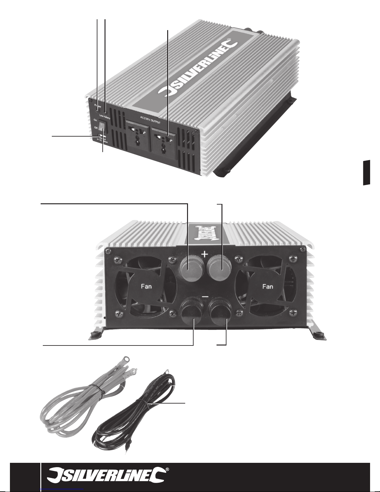
Product Familiarisation
1 Power Indicator Light
2 Low Battery Indicator Light
3 230V Universal Mains Sockets
4 On/Off Switch
5 USB sockets
6 12V Connectors
7 12V Cables
Intended Use
Device for converting 12V DC into AC mains voltage so mains-operated devices can be
used from a 12V DC supply. The device can be used in fixed locations or in vehicles.
Fig. A
Fig. C
Battery
Battery
Inverter
Inverter
Vehicle
Chassis
BatteryBattery
Fig. B
L
AC
NEN
N
Fig. D
Sine
Wave
Battery
Stationary
Ground
Inverter
L
NEN
N
Modified
Sine
Wave
(MSW)
AC
Unpacking Your Tool
• Carefully unpack and inspect your new tool. Familiarise yourself with all its features
and functions
• Ensure that all parts of the tool are present and in good condition. If any parts are
missing or damaged, have such parts replaced before attempting to use this tool
Before Use
Installing your inverter
WARNING: If you have any doubt about your ability to install an inverter, have it
installed by or consult a qualified electrician.
WARNING: If the inverter is modified to bond neutral to earth, this will invalidate the
suggested earth wiring in this manual, including connecting earth to a vehicle’s chassis.
• Always read the vehicle’s manual in combination with these instructions when installing
an inverter
• Always mount the inverter level and horizontal so that the internal fans extract the
heat with maximum efficiency. The inverter can be mounted upside down as long as
the body remains level and horizontal. Use the mounting holes at the base to secure
to a surface
• The inverter should ideally be located as close as possible to the battery but not placed
in the engine bay or battery compartment
• Ensure the position of the inverter allows for easy access to the On/Off Switch (4)
• Do not use the inverter in a dirty or dusty environment. It is important the inverter has
good ventilation and the fan outlets, vents and mains socket are free of dust and debris
• Always position the inverter away from direct sunlight and other heat sources. Only use
the inverter when the ambient air temperature is between 10-30˚C
• Allow adequate ventilation by ensuring there is always at least 25mm clear space
around the inverter. Do not place anything on top of the inverter
• In a vehicle the earth connection is made through the negative 12V connectors and uses
the vehicles own negative earth system
• When earthing the inverter in a boat, check the supplied boat manual for recommended
earthing. Additional components may be required
• In a stationary location, the inverter MUST be connected to a ground rod (a metal rod
driven into the earth) or other earthing point (Fig. B). Connect the negative terminal of
the battery, or one of the batteries in a battery bank, to 4mm2 or larger copper insulated
wire or bare wire with an insulation sleeve (preferably green/yellow) to an earth rod
which should be inserted into the ground to form an earth connection. Alternatively
connect to a pre-installed earthing point
www.silverlinetools.com
5
Page 6

GB
• When used in a vehicle, the inverter should only be used with 12V DC negative earth
electrical system. Use with any other type of vehicle earth system may be dangerous
and could cause permanent damage to the inverter and other electrical components
WARNING: Do not operate this inverter without connecting it to earth. Electrical shock
hazard may result.
Connecting to a battery
WARNING: When working next to, or moving lead acid batteries ensure you are
wearing splash-resistant safety goggles and electrically insulated gloves.
WARNING: The maximum input current of this inverter (12V/200A) exceeds the
output of most alternators fitted to cars and light vans, which normally have a current
output of approximately 60-70A. This inverter used to maximum capacity for an extended
duration - even while the engine is running - will require current well beyond the spare
current capacity of the alternator, and will discharge the battery until fully discharged and
the vehicle cannot be started.
IMPORTANT: Normal automotive (SLI) batteries are not recommended for use with this
inverter if the inverter is used at its maximum output for extended periods, especially if
the inverter is used in a stationary position that does not benefit from having a vehicle
alternator providing part of the current requirements. Recommended battery types are
deep cycle (leisure) or traction batteries. These are purposely designed to be depleted fully
at a low to medium rate and recharged frequently, but do not provide the peak current
output of automotive batteries that is required for starting a vehicle.
Notes:
• If you wish to replace the supplied 12V cables with longer cables, connect cables
that are suitable for the sustained inverter current demands, not peak/surge (see
Specification). Also make sure the insulation of the cable is correct for the environment
the cables will be used in
• To use this inverter at full capacity in a vehicle may require fitting of a higher
performance alternator
• When connecting multiple batteries in parallel, ideally all batteries should be the same
type, manufacturer, age and capacity. This will help provide the same level of current
and runtime across all batteries and mean they will age and can be replaced at the
same time with minimal waste of battery life. A worn battery with reduced capacity is
the weak link in a battery bank and prevents the full benefits of a bank being realised
• It is safer to use normal automotive (SLI) batteries in a parallel arrangement with an
inverter as the sustained high discharge rate is shared across multiple batteries. This
can help such batteries last longer, which otherwise may wear out very quickly when
used individually with inverters
• If fitting an inline fuse to improve protection against short circuits and overloads,
connect inline to the cable that attaches to the inverter’s 12V positive terminal. Select a
suitable fuse based on the maximum sustained input current of the inverter, and choose
a fuse at the closest value above this. So an inverter rated at 93A would need a 100A
continuous (anti-surge/time delay) rated fuse. Do not use a quick or fast-blow-type fuse
due to the peak current demands of AC devices when they are started. A suitable fuse
and fuse holder are available as Maxi blade type or Mega™ fuses for higher values
• When batteries need charging in a stationary installation and the battery charger
used allows for charging multiple batteries simultaneously, make sure the inverter is
switched off or disconnected while charging to prevent possible damage to the inverter
and battery charger. Check the instructions supplied with the battery chargers for
exact information
1. Switch the On/Off Switch (4) to the off position
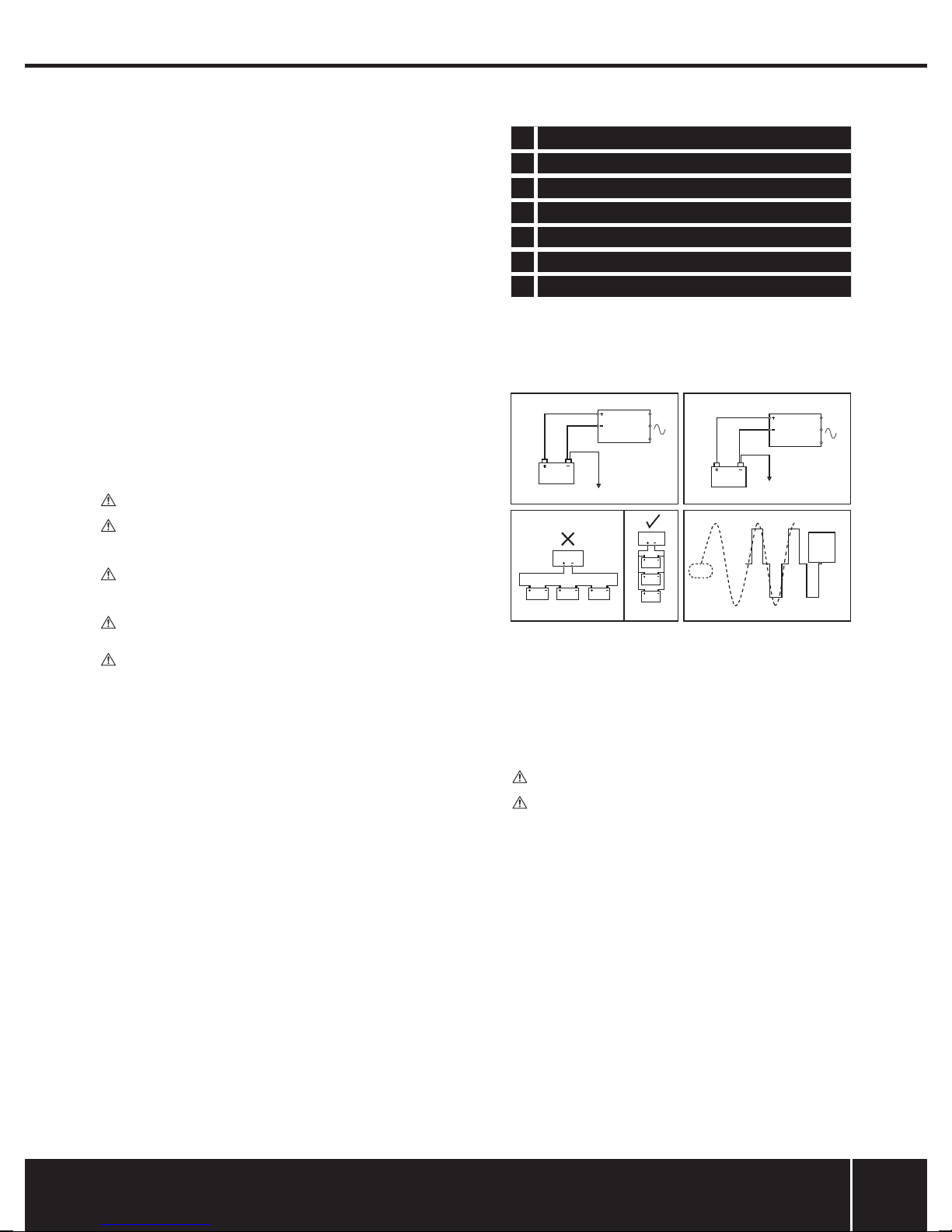
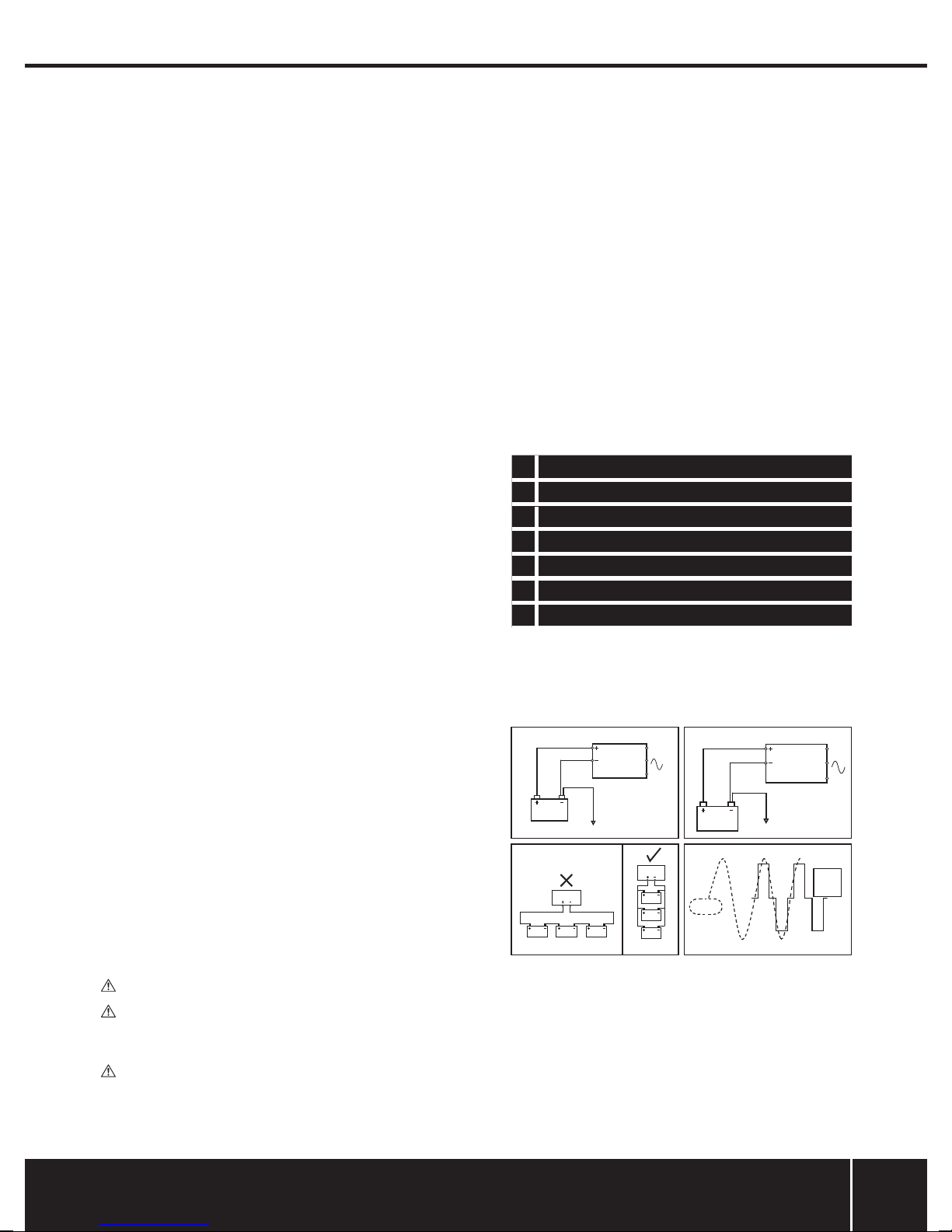
2. Connect the 12V Cables (7) to the battery as shown in Fig. A for vehicles or boats, or Fig.
B for a stationary installation. Make sure the cables are not shorted together
3. If you are connecting multiple batteries in a stationary installation, ensure they are
connected in parallel (Fig. C). Do not connect in series as the inverter and possibly the
batteries will be damaged. Parallel requires all negative battery terminals to be
connected to the negative terminal of the inverter and all positive battery terminals to
be connected to the positive terminal of the inverter. The inverter features 2 sets of
12V terminals so a simple 2 battery parallel connection only needs each battery
connected to one set of terminals. Double check the batteries are correctly connected
before connecting to the inverter
4. Remove the knobs of the 12V Connectors (7) and (8) and attach the free ends of the 12V
cables. Connect the black 12V cable to the Negative Connector (-) and the red 12V cable
to the Positive Connector (+). Tighten the knobs. Check the cables are connected to the
correct connectors. Connecting to the Positive Connector (+) of the inverter should
be the final connection made. It is important that the polarity is correct as the inverter’s
internal fuses will be blown by incorrect polarity
Operation
Connecting a mains device
WARNING: This inverter is not compatible with devices that have a capacitive power
supply; due to their design they will not work with the simulated AC voltage (modified
sine wave) of this inverter. Such power supplies are no longer sold from new in Europe
due to their reliance on pure sine wave AC and are fairly rare. They do not meet current
European safety standards but if you suspect your device has such a power supply, make
sure you monitor the device when first connected. If it is a battery charger that contains
a rechargeable battery of any type it is recommended not to try it due to the possibility of
damage to the batteries.
WARNING: If the inverter is constantly running at a very high temperature or is
shutting down in use, it is possible the device connected to the inverter is not ideally
matched and should not be connected. Always monitor the inverter and mains device
when connected for the first time for the first 5 minutes or so to ensure both are working
correctly at normal temperatures, then check on the device every half hour for the first 2
hours. Once the device is confirmed as compatible mark it so its compatibility is recorded.
WARNING: The 230V Universal Mains Sockets (3) fitted to the inverter are a universal
type which accommodates a wide range of world mains plugs. It is important when using
devices fitted with a non-UK or European plug that you check the device is compatible
with 230V 50Hz. This is especially important for devices intended for the US market; these
will normally be 120V 60Hz only and must not be connected. Only if the rating label of
the product specifically states a wide input voltage and dual mains frequency, for example
‘100-240V - 50/60Hz’, can they be used.
IMPORTANT: The inverter is reliant on being connected to a DC power source sufficient to
power your AC mains devices. It is not a fault with the inverter if the current is inadequate
to power your mains devices.
IMPORTANT: The 2000W Inverter’s maximum output is 2000W. Multiple lower wattage
devices can be used at the same time, but the total power being drawn from the Inverter
must not exceed 2000W.
IMPORTANT: If you are using an RCD with the inverter check that the inverter is operating
normally. As with all RCDs use the test button to make sure it is operating correctly before
use. If the RCD is not operating normally with an inverter this does not indicate a fault with
the inverter or RCD and is likely caused by either the modified sine wave output or lack of
neutral/earth bonding you would get from normal domestic sockets.
IMPORTANT: The inverter may shut down as a vehicle engine is being started due to the
high electrical current required by the vehicle starter motor. Ideally turn off the inverter
before starting the vehicle.
Notes
• The inverter simulates mains AC voltage using a modified sine wave (Fig. D). A small
number of devices may not be compatible with this type of AC waveform. Most
resistive-load devices (kettles, filament bulbs etc) are compatible. Inductive loads,
typically those that have electrically powered moving parts or have circuit boards with
electronic components, are more likely to be incompatible. These have components
that make use of magnetic fields and often require a high starting current as well as
being more selective about the AC wave form. Generally even domestic mains sockets
don’t output pure sine wave AC but their waveform is closer to pure sine wave than a
modified sine wave inverter. Many devices are designed to work with AC wave forms
that are not pure sine wave, so most devices are compatible with modified sine wave
output
• Some inductive load devices may consume slightly more current or produce more noise
with modified sine wave AC compared to pure sine wave AC
• Some devices have huge starting current requirements which means even if the
average power consumption is well within the inverter’s rating the device will not
be compatible. Pumps and compressors typically have the highest starting current
requirements (a refrigerator is a common device of this type). Generally an inductive
load with the same wattage power as a resistive load is less likely to be compatible due
to starting current requirements although some resistive loads still have higher starting
current requirements like filament bulbs
• If an inductive load device will not function at all with the inverter, or is not functioning
correctly, connecting a resistive load device with the inductive load may enable it to
function normally. A small lamp with a filament bulb may be suitable as a resistive load
• DO NOT use this inverter for sensitive devices such as medical equipment or any other
critical or calibrated electronic device that may not be compatible with modified sine
wave AC
• When used with audio-visual devices, it is possible additional background noise will be
heard in use and possible video distortion or interference. This could be due to many
reasons, including interference from the inverter or vehicle electrics as well as the
modified sine wave AC effecting components in the device. It is possible such a device
will not be compatible with a modified sine wave inverter, and a pure sine wave inverter
will be required for the device to work optimally
• Some devices, including laptops, mobile phones, and handheld electronic devices, have
AC power supplies to generate DC that the main unit requires to operate or charge its
battery. It is more efficient for such devices to be charged using a 12V charging lead
(possibly supplied with the unit) as this eliminates the conversion loss from converting
12V DC to high voltage AC in the inverter and then high voltage AC back to low voltage
DC in the AC power supply
• Some appliances (televisions, stereos, motors, neon lights etc) may require a much
higher starting power than their rated power. If the appliance will not start, the
maximum output of the inverter has been exceeded. To reduce the total load on the
inverter it may be possible to start the device by turning off other devices connected to
the inverter and then powering them up again, after you have started the device that
requires a very high starting current. If the inverter switches off due to high starting
current demands, this does not indicate a fault
6
Page 7

Inverter 2000W444658
• When checking AC output from an inverter with a multimeter, unless the multimeter
has a true RMS feature, it will give a low voltage reading from the output of a modified
sine wave inverter. This is normal and not an indication that the inverter or multimeter
is faulty
• Use a plug-in power monitor plugged into a domestic AC mains socket to find out the
true power consumption of an AC device. Ideally use a power monitor with a peak
current facility that will indicate the required starting current of a device
• If the appliance to be connected does not have its wattage (W) indicated on it, the
wattage can be calculated by multiplying the amperes (A) by 230
• When you have finished powering a mains device with the inverter, turn the On/
Off Switch (4) to off. The inverter always consumes power when turned on. See
‘Specification’ for the inverter power consumption without load. It is possible for the
inverter to drain a battery and prevent starting of a vehicle if left on, even without a load
1. Before connecting any appliance to the inverter, switch the On/Off Switch (4) to the
‘On’ position. After a few moments, the green Power Indicator Light (1) will illuminate.
The inverter is now ready for use
2. Do not connect loads greater than the rated maximum continuous power output
(2000W) of the inverter (see ‘Specification’). The Inverter’s maximum capacity is 2000W.
This may be drawn from a single socket or from a combination of the sockets, but the
total capacity of 2000W must not be exceeded. For example, using 2 x 1000W devices
is acceptable, but using 2 x 2000W devices is unacceptable.
3. Connect your AC device to either of the 230V Universal Mains Sockets (3).
Calculating Load and Runtime
• Ah rating of batteries is an approximate figure that is rarely true when a battery is
discharged at a very high rate. A 100Ah battery discharged at 5A for 20 hours is more
likely to last 20 hours than when discharged at 100A for 1 hour which will likely be fully
discharged before 1 hour
• To calculate the maximum wattage output of a battery for one hour, multiply its Ah
figure by its voltage (12V), for example a 100Ah battery is capable of 1200W for one
hour
• An easy way to calculate the approximate runtime of a mains device when connected
to an inverter and battery with a known amperes power consumption value, is to
multiply by 20 and divide the Ah figure of the battery by this calculated figure to get an
approximate figure in hours
• Convert Watts into Amperes by dividing Watts by voltage (230). Convert Amperes into
Watts by simply multiplying by 230
Protection Features
• Input over voltage: the inverter will switch off if the input DC voltage reaches or exceeds
16V. This indicates a poorly-regulated electrical system in the vehicle
• Input low voltage: the inverter will switch off if the DC voltage is approximately 10V.
This prevents damage to AC devices due to insufficient AC voltage. The DC voltage may
already be inadequate for starting the vehicle at this point. The inverter will audibly
indicate low voltage from approximately 10.5V to 10V before shutting down
• Output overload: the inverter will switch off if the sustained or peak current
requirements of the AC device or devices is too high for the inverter or the peak starting
current requirements are within the inverter specification but are lasting beyond the 1
second limit for peak current
• Output short-circuit: If there is a short circuit in the AC connections the inverter will shut
off. The internal fuses of the inverter may be blown and will need replacement at an
authorised service centre
• Overheat protection: The inverter will shut off if the internal temperature of the inverter
has reached approximately 55°C. This may occur due to inadequate ventilation,
incorrect installation, poor compatibility with an AC device, or simply due to the inverter
being used for a long period at maximum capacity. The built-in fan of the inverter is
temperature-controlled to reduce current demands of the inverter
IMPORTANT: Always try to prevent these protection features from operating in the first
place. However, it is possible that damage has already occurred before they operate.
IMPORTANT: When restarting the inverter after shutdown, make sure the issue that caused
the shutdown has been corrected.
Using the USB sockets
• The inverter is fitted with two USB sockets (5), which provide a maximum of 500mA
current each. If you have a device that can be charged via USB or mains, always use the
USB as it makes more efficient use of energy
Disposal
Always adhere to national regulations when disposing of power tools that are no longer
functional and are not viable for repair.
• Do not dispose of power tools, or other waste electrical and electronic equipment
(WEEE), with household waste
• Contact your local waste disposal authority for information on the correct way to
dispose of power tools
Accessories
• A range of accessories are available from your Silverline stockist. Spare parts can be
obtained from toolsparesonline.com
Maintenance
WARNING: ALWAYS disconnect from the power supply before carrying out any
inspection, maintenance or cleaning.
WARNING: The inverter contains no user serviceable parts. Some internal components
retain a dangerous high charge level even when disconnected from power. In the event a
short circuit occurs and blows the internal fuses, even though spare fuses may be supplied
these should be replaced by an authorised service centre or qualified electrician.
Cleaning
• Keep your tool clean at all times. Dirt and dust will cause internal parts to wear quickly,
and shorten the machine’s service life. Clean the body of your machine with a soft
brush, or dry cloth. If available, use clean, dry, compressed air to blow through the
ventilation holes
• Never use caustic agents to clean plastic parts
www.silverlinetools.com
7
Page 8
GB
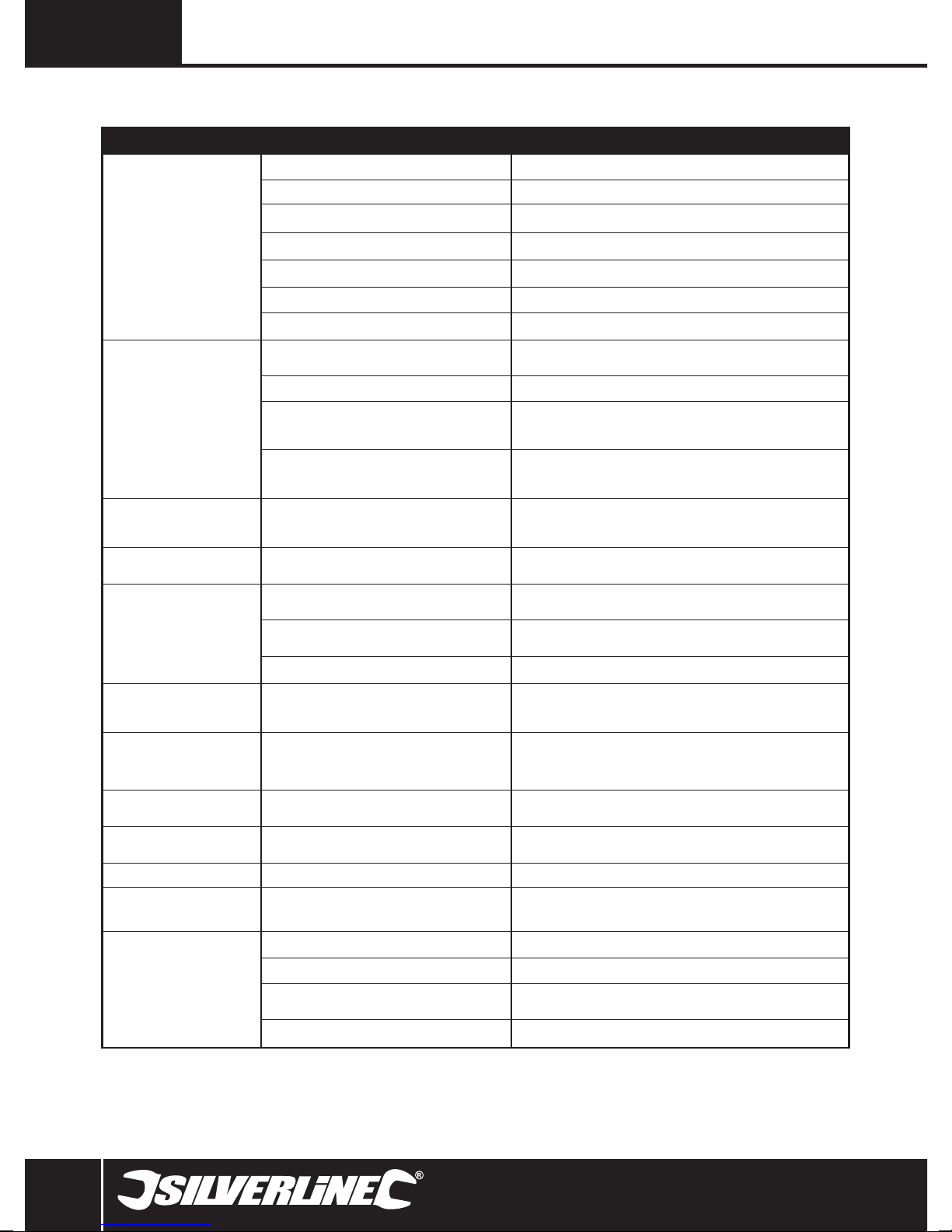
Troubleshooting
Problem Cause Solution
Low battery voltage Charge or replace battery
An incompatible AC device is connected Disconnect AC device
Inverter in thermal shutdown Allow inverter to cool before switching on
Inverter will not switch on
Low voltage alarm on continuously or
Low voltage shutdown operating
Low output voltage
AC mains device causes inverter to
go into overload shutdown
AC mains device will not start but
inverter does not go into overload
shutdown
AC device runs hot or is more
noisy than normal but operates
satisfactorily
DC cables are poorly connected Check DC leads for damage and secure connections
Internal fuses 'blown' possibly due to short circuit Have inverter serviced at an authorised service centre
Inline fuse blown if fitted Replace fuse
High alternator voltage Vehicle electrical system may have poor voltage regulation and require repair
One or more batteries in a battery bank is faulty or end of
DC cables are inadequate or poorly connected Recheck cables are suitable and correctly connected
Vehicle electrical system is under very high load with battery
at low charge and alternator is not able to charge both
battery and provide adequate power to inverter
Low capacity battery that is only capable of handling high
current demands from the inverter for a short time before
Incorrectly measured with a multimeter or other voltage
measurement tool without a true RMS mode which will give
Device requires either too much current continuously or has
too high starting current requirements
Insufficient DC power. Battery or batteries simply not capable
of delivering the required level of current
Inductive load AC device not compatible with modified
AC device not fully compatible with modified sine wave AC It is recommended not to use the device
service life
Inverter current demands are too high for the vehicle’s electrical system. Reduce
Replace battery with higher capacity model or if possible a deep cycle (leisure) or
a voltage drop
a low voltage reading
Device not compatible with inverter or you have overloaded inverter with too many
Calculate the required DC current and check the DC current available is sufficient
sine wave AC
AC device not compatible Check AC device manual/instructions/specifications to check compatibility
current demands or upgrade vehicle electrical system
traction battery which are more suitable for inverters
Measure with a true RMS multimeter or voltage measuring tool
Try pairing with a low power resistive load device like a small filament lamp
Replace battery or batteries
AC devices
AC device with a built-in timer or
clock is not keeping accurate time so
its functions are not correctly timed
AC power line network adapter does
not operate
RCD plugged into inverter does not
operate normally
AC device abnormal operation Incompatible with modified sine wave AC output DO NOT use with inverter
AC device instructions gives warning
about not using with inverters
Video and/or audio interference
when AV equipment is used with
inverter
If the device uses the AC waveform to regulate its timer
rather than a crystal oscillator it will not work correctly with
These devices do not normally work correctly with a modi-
This indicates the device is not compatible with a modified
AV equipment not operating correctly with modified sine
AV equipment picking up interference from vehicle ignition Consult a vehicle electrician on how to suppress interference
a modified sine wave inverter
fied sine wave AC waveform
RCD is not compatible with inverter DO NOT use with inverter
sine wave inverter and may be damaged by doing so
Inverter is used too close to aerial Move inverter or aerial
Aerial cable not shielded or insufficiently shielded Use fully shielded cable with correctly fitted connectors
wave output
Use normal network cabling which is also a more efficient use of power
Device is not fully compatible
DO NOT use with inverter
AV equipment not compatible with inverter
8
Page 9

www.silverlinetools.com
12V Inverter 444658
Silverline Tools Guarantee
This Silverline product comes with a 3 year guarantee
Register this product at www.silverlinetools.com within 30 days of purchase in order to
qualify for the 3 year guarantee. Guarantee period begins according to the date of purchase
on your sales receipt.
Terms & Conditions
Guarantee period becomes effective from the date of retail purchase as detailed on your
sales receipt.
PLEASE KEEP YOUR SALES RECEIPT
If this product develops a fault within 30 days of purchase, return it to the stockist where it
was purchased, with your receipt, stating details of the fault. You will receive a replacement
or refund.
If this product develops a fault after the 30 day period, return it to:
Silverline Tools Service Centre
PO Box 2988
Yeovil
BA21 1WU, UK
The guarantee claim must be submitted during the guarantee period.
You must provide the original sales receipt indicating the purchase date, your name, address
and place of purchase before any work can be
carried out.
You must provide precise details of the fault requiring correction.
Claims made within the guarantee period will be verified by Silverline Tools to establish if the
deficiencies are related to material or manufacturing of the product.
Carriage will not be refunded. Items for return must be in a suitably clean and safe state for
repair, and should be packaged carefully to prevent damage or injury during transportation.
We may reject unsuitable or
unsafe deliveries.
All work will be carried out by Silverline Tools or its authorized
repair agents.
The repair or replacement of the product will not extend the period
of guarantee
Defects recognised by us as being covered by the guarantee shall be corrected by means of
repair of the tool, free of charge (excluding carriage charges) or by replacement with a tool
in perfect working order.
Retained tools, or parts, for which a replacement has been issued, will become the property
of Silverline Tools.
Registering your purchase
Registration is made at silverlinetools.com by selecting the Guarantee Registration button.
You will need to enter:-
• Your personal details
• Details of the product and purchase information
Once this information is entered your guarantee certificate will be created in PDF format for
you to print out and keep with your purchase.
The repair or replacement of your product under guarantee provides benefits which are
additional to and do not affect your statutory rights as a consumer.
What is covered:
The repair of the product, if it can be verified to the satisfaction of Silverline Tools that the
deficiencies were due to faulty materials or workmanship within the guarantee period.
If any part is no longer available or out of manufacture, Silverline Tools will replace it with a
functional replacement part.
Use of this product in the EU.
What is not covered:
Silverline Tools does not guarantee repairs required as a result of:
Normal wear and tear caused by use in accordance with the operating instructions eg
blades, brushes, belts, bulbs, batteries etc.
The replacement of any provided accessories drill bits, blades, sanding sheets, cutting discs
and other related items.
Accidental damage, faults caused by negligent use or care, misuse, neglect, careless
operation or handling of the product.
Use of the product for anything other than normal domestic purposes.
Change or modification of the product in any way.
Use of parts and accessories which are not genuine Silverline Tools components.
Faulty installation (except installed by Silverline Tools).
Repairs or alterations carried out by parties other than Silverline Tools or its authorized
repair agents.
Claims other than the right to correction of faults on the tool named in these guarantee
conditions are not covered by the guarantee.
Battery Guarantee
Silverline batteries are guaranteed for 30 days. If a defect occurs on a registered battery
during the term of the Battery Guarantee, due to material or manufacturing fault, then
Silverline will replace it free of charge. This guarantee does not apply to commercial use nor
does it extend to normal wear and tear or damage as a result of accident, abuse or misuse.
CE Declaration of Conformity
The undersigned: Mr Darrell Morris
as authorised by: Silverline Tools
Declares that
This declaration has been issued under the sole responsibility of the manufacturer.
The object of the declaration is in conformity with the relevant Union harmonisation
Legislation.
Identification code: 444658
Description: 12V Inverter
Conforms to the following directives and standards:
• Low Voltage Directive 2006/95/EC
• EMC Directive 2004/108/EC
• RoHS Directive 2011/65/EU
• EN 60950-1:2006+A11+A1+A12
• EN 61000-6-3:2007+A1
• EN 61000-6-1:2007
Notified body: TÜV Product Service Ltd.
The technical documentation is kept by: Silverline Tools
Date: 06/01/14
Signed:
Mr Darrell Morris
Managing Director
Name and address of the manufacturer:
Powerbox International Limited, Company No. 06897059. Registered address: Powerbox,
Boundary Way, Lufton Trading Estate, Yeovil, Somerset BA22 8HZ, United Kingdom.
9
Page 10
FR
Traduction des instructions originales
Introduction
Nous vous remercions d’avoir choisi cet équipement Silverline. Ces instructions
contiennent les informations nécessaires pour vous en garantir un fonctionnement efficace
et en toute sécurité. Veuillez lire attentivement ce manuel pour vous assurer de tirer
pleinement avantage des caractéristiques uniques de votre nouvel équipement.
Gardez ce manuel à portée de main et assurez-vous que tous les utilisateurs l’aient lu et
bien compris avant toute utilisation. Conservez-le pour toute référence ultérieure.
Description des symboles
La plaque signalétique figurant sur votre outil peut présenter des symboles. Ces symboles
constituent des informations importantes relatives au produit ou des instructions
concernant son utilisation.
Port de protection auditive
Port de lunettes de sécurité
Port de masques respiratoires
Port du casque
Port de gants
Lire le manuel d’instructions
Risque d’électrocution
Risque d’incendie !
NE PAS utiliser sous la pluie ou dans un environnement humide !
Appareil de Classe I (masse de protection)
Attention !
Caractéristiques techniques
Plage de tension d'entrée :..................................................10 -15 V (12 V) DC
Courant d'entrée max :........................................200 A (pic 250 A, 1 seconde)
Tension de sortie : ................................................................................ 230 V~
Fréquence de sortie : ..............................................................................50 Hz
Forme d’onde : ................................................................Sinusoïdale modifiée
Prise USB : ................................................................................5 V CC 500mA
Classe de protection de l’onduleur : ........................................................
Prises principales : ..........................................................................Universelle
Classe de protection de la prise principale : ..........................................
Puissance de sortie continue maximale : .................................2 000 W (8,7 A)
Capacité/temps de démarrage : .............................4 000 W pour une seconde
Rendement : .........................................................................................>88 %
Consommation de courant à vide : ........................................................<1.0 A
Alarme de basse tension : .............................................................10,5 ±0,5 V
Arrêt basse tension : ........................................................................ 10 ±0,5 V
Température maximale de service : ..................................................XX-XX °C
Température ambiante recommandée : ............................................ 10-32 °C
Dispositif de protection :.....................................Sous tension à l’entrée (16 V)
Tension d’entrée basse
Surcharge à la sortie
Court-circuit à la sortie
Surchauffe
Indice de protection :.................................................................................IPx0
Longueur du câble fourni : ............................................................... 1 m (env.)
Dimensions (L x l x h) : ....................................................330 x 200 x 100 mm
Poids : ....................................................................................................4,8 kg
Risque d’explosion !
NE PAS exposer à une flamme nue !
NE PAS fumer à proximité !
Usage à l’intérieur seulement !
Conforme à la réglementation et aux normes de sécurité pertinentes
Protection de l’environnement
Les produits électriques usagés ne doivent pas être jetés avec les ordures
ménagères. Veuillez les recycler dans les centres prévus à cet effet. Pour
de plus amples informations, veuillez contacter votre municipalité ou
point de vente
Abréviations pour les termes
techniques
V Volts
~ Courant alternatif
A Ampère
Hz Hertz
W, kW Watt, kilowatt
Ah Ampère-heure
Du fait de l’évolution constante de nos produits, les caractéristiques
des produits Silverline peuvent changer sans notification préalable.
Consignes générales de sécurité
ATTENTION : Veuillez lire l’intégralité des consignes de sécurité et des instructions.
Le non-respect de ces consignes et instructions peut entraîner un risque de choc
électrique, d’incendie et/ou se traduire par des blessures graves.
ATTENTION : Cet appareil n’est pas conçu pour être utilisé par des personnes
(enfants compris) ayant des capacités physiques ou mentales réduites, ou n’ayant
pas la connaissance ou l’expérience requise, à moins d’être sous la supervision
d’une personne responsable de leur sécurité ou d’avoir reçu les instructions
nécessaires. Les enfants ne doivent pas s’approcher et jouer avec cet appareil.
Veuillez conserver ces instructions et consignes de sécurité pour référence ultérieure.
1) Sécurité sur la zone de travail
a) Maintenir une zone de travail propre et bien éclairée. Des zones encombrées et mal
éclairées sont sources d’accidents.
b) Ne pas utiliser d’outils électriques dans des environnements explosifs, tels qu’à
proximité de liquides, de gaz ou de poussières inflammables. Les appareils
électriques produisent des étincelles susceptibles d’enflammer la poussière ou les
vapeurs présentes.
c) Eloigner les enfants et les passants pendant l’utilisation d’un appareil électrique.
Ceux-ci peuvent provoquer une perte d’attention et faire perdre la maîtrise de l’appareil.
2) Sécurité électrique
a) La prise d’un appareil électrique doit être adaptée à la prise du secteur. Ne jamais
modifier la prise en aucune façon. Ne jamais utiliser d’adaptateur sur la prise
électrique d’appareil mis à la terre. Des prises non modifiées, adaptées aux boîtiers
de prise de courant, réduiront le risque de décharge électrique.
b) Eviter le contact corporel avec les surfaces mises à la terre telles que tuyaux,
radiateurs, cuisinières et réfrigérateurs. Le risque de décharge électrique est plus
important si le corps est mis à la terre.
c) Ne pas exposer l’appareil électrique à la pluie ou à l’humidité. L’infiltration d’eau
dans un appareil électrique accroît le risque de décharge électrique.
d) Ne pas maltraiter le cordon électrique. Ne jamais utiliser le cordon électrique pour
porter, tirer ou débrancher l’appareil. Protéger le cordon électrique de la chaleur,
du contact avec l’essence, des bords tranchants et pièces rotatives. Un cordon
électrique endommagé ou entortillé accroît le risque de décharge électrique.
10
Page 11
www.silverlinetools.com
Onduleur 12 V444658
du véhicule
Véhicule
Terre
e) Lors d’une utilisation de l’appareil électrique en extérieur, se servir d’une rallonge
appropriée à une utilisation en extérieur. Cela réduit le risque de décharge électrique.
f) Si une utilisation de l’appareil électrique dans un environnement humide ne
peut être évitée, utiliser une alimentation protégée par un disjoncteur différentiel.
L’utilisation d’un disjoncteur différentiel réduit le risque de décharge électrique.
3) Sécurité des personnes
a) Rester vigilant et faire preuve de bon sens lors de la manipulation de l’appareil.
Ne pas utiliser un appareil électrique lorsque l’on se trouve dans un état de
fatigue, ou sous l’influence de drogues, d’alcool ou de médicaments. Un moment
d’inattention pendant l’utilisation d’un outil électrique peut se traduire par des blessures
graves.
b) Porter un équipement de protection approprié. Toujours porter une protection
oculaire. Le port de masque à poussières, chaussures de sécurité antidérapantes,
casque de sécurité et protections antibruit adaptés aux différentes conditions de travail
réduit le risque de blessures corporelles.
c) Eviter tout démarrage accidentel ou intempestif. S’assurer que l’interrupteur
marche-arrêt soit en position d’arrêt avant de brancher l’appareil sur
l’alimentation secteur ou d’installer la batterie, de prendre l’appareil ou de
le transporter. Porter un appareil électrique tout en maintenant le doigt posé sur
l’interrupteur ou brancher un appareil électrique dont l’interrupteur est sur la position de
marche est source d’accidents.
d) Enlever toute clé et tout instrument de réglage avant de mettre l’appareil
électrique en marche. Une clé ou un instrument de réglage laissé fixé à un élément en
rotation de l’appareil électrique peut entraîner des blessures physiques.
e) Ne pas essayer d’atteindre une zone hors de portée. Se tenir toujours en position
stable permettant de conserver l’équilibre. Cela permet de mieux contrôler l’appareil
électrique dans des situations inattendues.
f) Porter des vêtements appropriés. Ne pas porter de vêtements amples ou des
bijoux pendants. Eloigner cheveux, vêtements et gants des pièces en mouvement.
Les vêtements amples, les bijoux pendants et cheveux longs peuvent être happés par
les pièces en rotation
g) Si l’appareil est pourvu de dispositifs destinés au raccord d’équipements
d’extraction et de récupération de la poussière/sciure, s’assurer qu’ils soient bien
fixés et utilisés correctement. L’utilisation de ces dispositifs peut réduire les risques
dus à la poussière.
4) Utilisation et entretien des appareils électriques
a) Ne pas forcer sur l’appareil électrique. Utiliser l’appareil électrique approprié au
travail à effectuer. Un appareil électrique adapté et employé au rythme pour lequel
il a été conçu permettra de réaliser un travail de meilleure qualité et dans de meilleures
conditions de sécurité.
b) Ne pas utiliser un appareil électrique dont l’interrupteur marche-arrêt est hors
service. Tout appareil électrique dont la commande ne s’effectue plus par l’interrupteur
marche-arrêt est dangereux et doit être réparé.
c) Débrancher l’appareil électrique ou démonter sa batterie avant d’effectuer
tout réglage ou changement d’accessoire et avant de le ranger. De telles mesures
préventives réduiront les risques de démarrage accidentel.
d) Ranger les appareils électriques inutilisés hors de portée des enfants et ne pas
permettre l’utilisation de cet appareil aux personnes non habituées à son
maniement ou n’ayant pas lu les présentes instructions. Les appareils électriques
sont dangereux dans les mains d’utilisateurs inexpérimentés.
e) Veiller à l’entretien des appareils électriques. Vérifier que les éléments rotatifs
soient bien alignés et non grippés. S’assurer de l’absence de pièces cassées
ou endommagées susceptibles de nuire au bon fonctionnement de l'appareil.
Si l’appareil électrique est endommagé, le faire réparer avant toute utilisation. De
nombreux accidents sont dus à l’utilisation d’appareils électriques mal entretenus.
f) Veiller à ce que les outils de coupe soient tenus affûtés et propres. Des outils de
coupe bien entretenus, aux tranchants bien affûtés, sont moins susceptibles de se
gripper et sont plus faciles à contrôler.
g) Utiliser l’appareil électrique, les accessoires et outils à monter conformément
à ces instructions, en tenant compte des conditions de travail et de la tâche à
réaliser. Toute utilisation d’un appareil électrique autre que celle pour laquelle il a été
conçu peut entraîner des situations à risque.
5) Révision
a) Ne faire réparer votre appareil électrique que par un réparateur qualifié utilisant
uniquement des pièces de rechange identiques. Cela permet de maintenir la
sécurité d’utilisation de l’appareil électrique.
Consignes de sécurité relatives à
l’utilisation d’un onduleur
ATTENTION : Tout comme les prises électriques domestiques, les onduleurs
produisent une tension CA dangereuse et potentiellement mortelle.
ATTENTION : N’utilisez pas d’onduleur dans un endroit où des gaz inflammables
peuvent être présent, comme dans le compartiment d’un moteur ou d’une batterie. Des
fumées inflammables peuvent émaner des batteries au plomb. Les appareils électroniques
et les connexions électriques peuvent engendrer des étincelles pouvant enflammer ces
fumées.
ATTENTION : Les personnes ayant un stimulateur cardiaque doivent demander l’avis
de leur médecin avant d’utiliser cet appareil. Des champs électromagnétiques puissants à
proximité immédiate d’un stimulateur cardiaque peuvent causer des interférences avec le
stimulateur ou sa défaillance.
• N’utilisez PAS l’onduleur dans un environnement humide, là où l’air a une teneur
en humidité élevée ou dans n’importe quelle situation où l’onduleur pourrait rentrer
en contact avec de l’eau. Cela peut engendrer l’impossibilité de l’utiliser en mer, en
particulier sur les bateaux de petite taille
• Lorsqu’il est utilisé dans un endroit fixe, l’onduleur doit être protégé totalement des
intempéries et couvert
• Ne le placez pas sur de la moquette ou sur un tapis, ils pourraient bloquer les aérations
situées sur le bas de l’onduleur et sont un risque d’incendie
• N’utilisez PAS de câbles CC non compatible avec la valeur du courant d’entrée
maximum de cet onduleur. Ni le véhicule ni l’onduleur ne détecteront si un câble
incompatible est utilisé. L’utilisation d’un câble non compatible engendre un risque
d’explosion et d’incendie
• N’installez PAS cet onduleur au système électrique d’un bâtiment. Il n’a pas été conçu
pour être installé en toute sécurité dans un tel système électrique et n’a ni été testé ou
certifié pour répondre aux normes électriques pour les bâtiments. De telles installations
peuvent engendrer un risque d’incendie ou de choc électrique.
• N’essayez PAS d’intégrer cet onduleur au système de distribution de 230 V préexistant
d’un camping-car ou d’une caravane. Un tel travail doit être effectué par un électricien
• NE branchez PAS cet onduleur sur la prise allume-cigare d’un véhicule. Il requiert une
intensité bien au-delà des capacités d’une telle prise
• Brancher un onduleur sur le circuit existant d’un véhicule comportant des fusibles peut
être extrêmement dangereux. Branchez toujours l’onduleur directement sur la batterie
du véhicule à moins d’être sûr que vous pouvez faire autrement. Si vous souhaitez que
l’onduleur se mette en marche et s’arrête en même temps que le contact du véhicule,
utilisez un relais sécurisé par un fusible afin qu’un circuit à faible intensité puisse mettre
en marche et arrêter une connexion à haute intensité directement connecté à la batterie
Descriptif du produit
1 Témoin d’alimentation lumineux
2 Témoin indicateur de batterie faible
3 Prise d’alimentation universelle 230 V
4 Bouton marche arrêt
5 Prise USB
6 Connecteurs 12 V
7 Câble 12 V
Usage conforme
Appareil destiné à la conversion CC en tension de secteur CA afin de pouvoir alimenter des
appareils utilisant le courant de secteur avec une alimentation CC, généralement en 12 V.
Cet appareil peut être utilisé fixe ou dans un véhicule.
Onduleur
Batterie
Batterie
Batterie
Fig. B
CA
Batterie
Fig. D
Onde
sinusoïdale
Fixe
Onduleur
L(P)
N(N)
E(T)
Onde
sinusoïdale
modifié
(OSM)
CA
Fig. A
Fig. C
Batterie
Batterie
Batterie
Batterie
Serie
Batterie
Onduleur
Châssis
L(P)
N(N)
E(T)
Parallèle
Déballer votre produit
• Déballez le produit avec soin et inspectez votre nouvel outil. Familiarisez-vous avec
toutes les caractéristiques du produit.
• Si des pièces sont endommagées ou manquantes, faites-les réparer ou remplacer avant
d’utiliser l’appareil.
11
Page 12
FR
Avant utilisation
Installer l’onduleur
ATTENTION : Si vous avez des doutes sur vos capacités à installer un onduleur,
consultez ou faites le installer par un électricien qualifié.
ATTENTION : Si l’onduleur est modifié pour relier le neutre à la terre, alors la mise
à la masse ainsi que la connexion de la terre sur le châssis du véhicule suggéré dans ce
manuel ne seront pas valide.
• Lisez toujours le manuel du véhicule en même temps que ces instructions lorsque vous
installez l’onduleur
• Montez toujours l’onduleur à l’horizontale et de niveau afin que le ventilateur puisse
évacuer la chaleur efficacement. L’onduleur peut être monté dessus dessous tant que
l’appareil reste de niveau et horizontal. Utilisez les trous de montages à la base pour
fixer l’onduleur sur une suface.
• Idéalement, l’onduleur devrait être installé le plus près possible de la batterie mais ni
dans le compartiment moteur ni dans celui de la batterie
• Assurez-vous que le bouton marche/arrêt (4) de l’onduleur est facile d’accès
• N’utilisez pas l’onduleur dans un environnement sale ou poussiéreux. Il est important
que l’onduleur bénéficie d’une bonne ventilation et les orifices du ventilateur, les
aérations et la prise principale doivent être exempts de poussière et de débris
• L’onduleur doit être positionné à l’abri des rayons directs du soleil et de toute autre
source de chaleur. N’utilisez l’onduleur que lorsque la température ambiante se situe
entre 10 et 30°C
• Assurez une bonne ventilation en veillant à avoir 25 mm d’espace libre tout autour de
l’onduler. Veillez à ne rien mettre sur l’onduleur
• Dans un véhicule, la mise à la terre est faite grâce aux connecteurs 12 V et utilisez le
système de mise à la tête par le négatif de la voiture.
• Lors de la mise à la masse de l’onduleur sur un bateau, vérifiez la mise à la masse
recommandée dans le manuel du bateau. Des composants supplémentaires peuvent
être nécessaires
• Dans un endroit fixe, l’onduleur DOIT être relié à une tige de terre (une tige métallique
enfoncée dans la terre) ou un autre point de mise à la masse (Fig. B). Branchez le
terminal négatif de la batterie, ou d’une des batteries du parc de batteries, à un fil en
cuivre de 4mm² ou plus isolé ou d’un câble nu protégé par un manchon isolant (de
préférence vert ou jaune) ou à une tige de mise à la masse plantée dans le sol. Ou,
branchez sur une masse déjà installée.
• Lorsqu’il est utilisé à bord d’un véhicule, l’onduleur devrait être utilisé uniquement
avec un système électrique CC 12 V avec négatif à la masse. L’utilisez avec tout autre
système de mise à la masse du véhicule peut être dangereux et peut entrainer des
dommages permanents à l’onduleur et à d’autres composants électriques
ATTENTION : N’utilisez pas cet appareil lorsqu’il n’est pas relié à la terre. Cela peut
entraîner un risque de choc électrique.
Brancher à une batterie
ATTENTION : Assurez-vous que vous portez des lunettes résistantes aux
éclaboussures et des gants isolants lorsque vous travaillez à proximité de, ou déplacez,
des batteries au plomb.
ATTENTION : Le courant d’entrée maximum de cet onduleur (12 V / 200 A) est au-delà
du courant de sortie de l’alternateur installé sur la plupart des voitures et des camionnettes
légères, dont le courant de sortie est en général aux environs de 60 - 70 A. Cet onduleur,
lorsqu’il est utilisé à sa capacité maximum pour une durée prolongée – même si le
moteur tourne – demande un courant bien au-delà de la capacité de l’alternateur, et peut
décharger la batterie complètement et le véhicule ne pourra pas être démarré.
IMPORTANT : Les batteries automobiles classiques (SLI) ne sont pas recommandées
pour un usage avec cet onduleur s’il est utilisé à sa capacité maximum pour une durée
prolongée, surtout si l’onduleur est utilisé dans un endroit fixe et ne bénéficie pas du
courant provenant de l’alternateur du véhicule pour l’alimenter. Il est recommandé
d’utiliser des batteries à décharge profonde (de loisir) ou de traction. Elles sont conçues
spécialement pour être déchargées totalement à un rythme lent ou moyen et rechargées
régulièrement, cependant elles ne fournissent pas de pic de courant de sortie au
démarrage des véhicules comme les batteries automobiles.
Remarques :
• Si vous souhaitez remplacer le câble 12 V fourni par un câble plus long, branchez
un câble adapté à la demande soutenue en courant de l’onduleur, pas de pic ou
d’augmentation (voir caractéristiques techniques). Assurez-vous également que
l’isolation du câble est adaptée à l’environnement dans lequel il est utilisé
• Afin d’utiliser l’onduleur à plein capacité dans un véhicule peut nécessiter un alternateur
plus performant
• En cas de branchement en parallèle de plusieurs batteries, il est recommandé
d’utiliser des batteries du même type, de la même marque, du même âge et de la
même capacité. Cela permettra de fournir le même niveau de courant et de temps de
fonctionnement à travers toutes les batteries. Cela signifie aussi qu’elles s’useront en
même temps qu’elles devront être remplacées simultanément. De plus leur durée de
vie sera optimisée. Une batterie usée ayant des capacités réduites est un maillon faible
dans le parc de batteries et ne permet pas de profiter pleinement du parc de batteries
mis en place
• Il est plus sûr d’utiliser des batteries automobiles normales (SLI) montées en parallèle
avec un onduleur puisqu’elles se partagent la décharge rapide. Cela peut permettre aux
batteries de durer plus longtemps. Autrement, elles pourraient s’user rapidement si elles
sont utilisées individuellement avec un onduleur
• Si un fusible de protection est installé pour lutter contre les courts-circuits et les
surcharges, effectuez un montage en série sur le câble le reliant à la borne positive
12 V de l’onduleur. Choisissez le fusible dont la valeur est la plus proche du courant
maximum de l’onduleur. Par exemple, un onduleur de 93 A nécessite un fusible de 100
A continu (anti-surcharge/temps de retard). Des fusibles à lame Maxi et Mega™ et des
portes fusibles sont disponibles
• Lorsque les batteries d’une installation fixe doivent être rechargées et si le chargeur
peut être utilisé pour charger plusieurs batteries en même temps, assurez-vous que
l’onduleur est arrêté ou débranché lors de la recharge afin de prévenir d’éventuels
dégâts sur l’onduleur et le chargeur. Pour de plus ample information référez-vous aux
instructions du chargeur.
1. Éteignez l’appareil en utilisant le bouton marche/arrêt (4).
2. Branchez le câble 12 V (7) à la batterie comme l’indique Fig. A pour les véhicules ou
bateaux, ou Fig.B pour les installations fixes. Assurez-vous que les câbles ne se court circuitent pas
3. Si vous branchez plusieurs batteries dans une installation fixe, assurez-vous qu’elles
sont branchées en parallèle (Fig. C). N’effectuez pas un branchement en série, cela
pourrait endommager l’onduleur et les batteries. Le montage en parallèle nécessite
que toutes les bornes négatives des batteries soient branchées sur la borne négative de
l’onduleur, et que toutes les bornes positives des batteries soient branchées sur la borne
positive de l’onduleur. L’onduleur dispose de 2 paires de terminaux 12 V, ainsi dans un
montage associant 2 batteries en parallèle, il suffit de brancher chacune d’elles sur une
paire de bornes. Vérifiez que les batteries sont correctement branchées avant de les
relier à l’onduleur.
4. Enlevez les boutons des connecteurs 12 V et attachez-y les extrémités libres des câbles
12 V. Banchez le câble 12 V sur le connecteur négatif (-) et le rouge sur le connecteur
positif (+). Resserrez les boutons. Vérifiez que les câbles sont branchés sur le bon
connecteur. Effectuez le branchement sur le connecteur positif (+) de l’onduleur en
dernier. Le fusible interne de l’onduleur fondra si les polarités ne sont pas respectées.
Mode d’emploi
Raccorder un appareil branché sur secteur
AVERTISSEMENT : Cet onduleur n’est pas compatible avec un appareil ayant une
alimentation capacitive. Leur conception ne permet pas de les utiliser avec la tension CA
simulée (onde sinusoïdale modifiée) par cet onduleur. De telles sources de courant sont
rares et ne sont plus vendues neuves en Europe du fait de leur dépendance au CA à onde
sinusoïdale parfaite. De plus, elles ne répondent pas aux standards européens de sécurité.
Cependant, si vous suspectez votre appareil de disposer d’une telle alimentation, surveillez
l’appareil lorsque vous le connectez pour la première fois. S’il s’agit d’un chargeur
contenant une batterie rechargeable de n’importe quel type, il est recommandé de ne pas
l’utiliser car la batterie pourrait être endommagée.
AVERTISSEMENT : Si la température de l’onduleur en fonctionnement et
constamment élevée ou s’il s’arrête pendant l’utilisation, il est possible que l’appareil
branché sur l’onduleur ne soit pas compatible et il ne devrait pas être branché. Lors de la
première utilisation avec un appareil, surveillez toujours l’onduleur et l’appareil pendant
environ 5 minutes pour vous assurer qu’ils fonctionnent correctement et sont à une
température normale. Ensuite, vérifiez l’appareil toutes les demi-heures pendant les 2
premières heures. Lorsque la compatibilité est vérifiée faites en note.
AVERTISSEMENT : Les prises d’alimentation universelles 230 V (3) de l’onduleur
conviennent à un grand nombre de prises du monde entier. Lors de l’utilisation d’un
appareil équipé d’une prise autre que britannique ou européenne il est important de vérifier
sa compatibilité avec du 230 V, 50 Hz. Cela est notamment nécessaire pour les appareils
destinés au marché Américain. Normalement, ces derniers fonctionnent avec du 120 V,
50 Hz et ne doivent pas être branchés sur cet onduleur. N’utilisez que des appareils dont
l’étiquette d’identification indique clairement qu’ils supportent une large plage de tension
d’entrée et une fréquence du secteur double ; par exemple : 100-240 V – 50/60 Hz.
IMPORTANT : L’oscillateur est dépendant de la source de courant CC pour alimenter un
appareil en CA. Il ne s’agit pas d’un défaut si l’onduleur n’est pas adapté à l’alimentation
en courant votre appareil.
IMPORTANT : La puissance maximale de cet onduleur est de 2 000 W. Plusieurs appareils
à basse tension peuvent être utilisés en même temps mais la puissance totale fournie par
l’onduleur ne doit pas être supérieure à 2 000 W.
IMPORTANT : Si vous utilisez un disjoncteur avec l’onduleur vérifiez que l’onduleur
fonctionne normalement. Testez toujours le disjoncteur à l’aide du bouton test pour vous
assurer qu’il fonctionne correctement. Si le disjoncteur ne fonctionne pas correctement
avec l’onduleur cela n’indique pas de défaut de l’onduleur ou du disjoncteur. Cela peut être
causé soit par l’onde sinusoïdale modifiée ou l’absence d’une connexion à la masse/au
neutre que vous auriez avec une prise électrique domestique classique.
IMPORTANT : L’onduleur peut s’arrêter lorsque le véhicule démarre. Cela est dû au courant
électrique important nécessaire pour le démarrage du moteur du véhicule. Dans l’idéal
arrêtez l’onduleur avant de démarrer le véhicule.
Remarques :
• L’onduleur simule la tension CA du secteur à travers une onde sinusoïdale modifiée
(Fig. D). Un petit nombre d’appareils n’est pas compatible avec ce type de forme
d’onde du CA. La plupart des appareils à charge résistive sont compatibles (bouilloires,
ampoules à filament etc.). Les charges inductives, généralement les appareils ayant
des pièces déplacées électriquement ou ayant un circuit intégré comportant des
composants électroniques, seront probablement incompatibles. Ceux-ci comportent des
composants utilisant des champs magnétiques et requièrent un courant de démarrage
fort en plus d’être plus sélectifs sur la forme de l’onde de CA. La plupart du temps le
courant des prises domestiques n’est pas un CA à onde sinusoïdale pure, cependant
la forme de l’onde est plus proche d’un sinus que l’onde sinusoïdale modifiée de
l’onduleur. De nombreux appareils sont conçus pour fonctionner avec des ondes du CA
n’étant pas des sinusoïdales pures, ainsi la plupart des appareils sont compatibles avec
un courant sinusoïdal modifié.
12
Page 13

www.silverlinetools.com
Onduleur 12 V444658
• Certains appareils à charge inductives peuvent consommer un peu plus de courant ou
faire plus de bruit lorsqu’ils sont alimentés par une source de courant sinusoïdal modifié
que lorsqu’ils sont alimentés par un courant CA pur.
• Certains appareils nécessitent un fort courant de démarrage, cela signifie que même si
leur consommation moyenne se situe dans la plage de fonctionnement de l’onduleur, de
tels appareils ne seront pas compatibles. Les pompes et les compresseurs nécessitent
généralement les courants de démarrage les plus hauts (un réfrigérateur est un appareil
classique de ce type). En règle générale, une charge inductive ayant la même puissance
qu’une charge résistive aura moins de chances d’être compatible à cause du courant
de démarrage qu’elle nécessite. Cependant, certaines charges résistives, comme les
ampoules à filament, nécessitent un fort courant de démarrage.
• Lorsqu’une charge inductive ne fonctionne pas correctement ou pas du tout avec
l’onduleur l’ajout d’un appareil à charge résistive à la charge inductive peut lui
permettre de fonctionner normalement. Une petite lampe avec une ampoule à filament
peut lui permettre de fonctionner correctement.
• N’utilisez PAS l’onduleur avec des appareils sensibles comme les équipements
médicaux ou d’autres appareils électroniques calibrés ou dangereux, ils pourraient être
incompatibles avec un CA à onde sinusoïdale modifiée.
• Lorsqu’il est utilisé avec un appareil multimédia, il est possible que des bruits de fond,
une distorsion de la vidéo ou des interférences apparaissent pendant l’utilisation. Cela
peut être causé par de nombreuses raisons, y compris des interférences provenant de
l’onduleur ou de l’alimentation de bord du véhicule ainsi que le CA à onde sinusoïdale
modifiée affecte les composants de l’appareil. Il est possible que ce type d’appareils
ne soit pas compatible avec un onduleur à onde sinusoïdale modifiée, et un onduleur à
onde sinusoïdale pure sera nécessaire pour le fonctionnement optimal de cet appareil.
• Certains appareils, comme les ordinateurs portables, téléphones portables et les
appareils électroniques portatifs, disposent d’une alimentation CA afin de générer
le CC nécessité par l’appareil principal pour fonctionner ou recharger sa batterie.
Pour recharger efficacement de tels appareils il est plus efficace d’utiliser le câble
12 V (souvent fournis avec l’appareil). En effet il permet l’élimination des pertes de
conversion du CC 12 V en CA haute tension d’abord dans l’onduleur, puis dans lors de la
transformation de la CA haute tension CC basse tension dans l’alimentation en CA.
• Certains appareils (télévisions, chaînes stéréos, moteurs, néons etc.) peuvent nécessiter
un courant de démarrage bien plus élevé que leur puissance nominale. Si l’appareil ne
s’allume pas, la puissance maximum de l’onduleur a été dépassée. Afin de réduire la
charge totale sur l’onduleur, il est possible d’envisager d’éteindre les autres appareils
branchés. Réessayez ensuite d’allumer l’appareil nécessitant un fort courant de
démarrage. Vous pouvez finalement rallumer les autres appareils. Si l’onduleur s’arrête
à cause de la forte demande en courant de démarrage cela ne doit pas être considéré
comme un défaut.
• Lorsque vous vérifiez la tension de sortie du CA de l’onduleur avec un multimètre, il
indiquera une tension basse à la sortie d’une tension sinusoïdale modifiée, à moins que
le multimètre ne dispose d’une fonction RMS (valeurs efficaces vraies). Cela est normal
et ni l’onduleur ni le multimètre ne doivent être considéré comme étant défectueux.
• Pour connaître la consommation réelle d’un appareil utilisant le CA utilisez un dispositif
de contrôle de puissance branché à une prise domestique alimentée en CC et reliée au
secteur. Dans l’idéal, utilisez un dispositif de contrôle de puissance indiquant les pics de
tension qui indiquera le courant de démarrage nécessaire à l’appareil.
• Si l’appareil devant être branché ne dispose pas d’indications de puissance (W), la
puissance peut être calculée en multipliant le nombre d’ampère (A) par 230.
• Lorsque vous avez fini d’alimenter un appareil avec l’onduleur, éteignez l’onduleur grâce
au bouton marche/arrêt (4). L’onduleur consomme toujours de l’énergie lorsqu’il est en
marche. Référez-vous aux caractéristiques techniques de l’onduleur pour en connaître
la consommation à vide. Lorsqu’il est laissé en marche même à vide, il est possible que
l’onduleur vide la batterie, empêchant le véhicule de démarrer.
1. Avant le branchement de n’importe quel onduleur, mettez le bouton marche/arrêt (4)
sur la position « marche ». Après quelques instants, le témoin d’alimentation lumineux
(1) s’allumera. L’onduleur est alors prêt à être utilisé.
2. Ne branchez pas de charge supérieure à la puissance de sortie continue maximale de
l’onduleur (2 000 W) (référez-vous aux caractéristiques techniques). La capacité
maximale de 2 000 W est la capacité totale de l’unité. Cela peut être tiré d’une seule
prise ou de la combinaison des deux, mais en aucun cas la capacité totale ne doit
excéder 2 000 W. Par exemple, vous pouvez utiliser deux appareils de 1 000 W chacun
alors que vous ne pourriez pas utiliser deux appareils de 2 000 W chacun mais un seul.
3. Connectez votre appareil utilisant le CA à l’une des prises d’alimentation universelle
230 V (3).
Dispositif de protection
• Surtension à l’entrée : l’onduleur s’éteindra si la tension du CC atteint ou dépasse 16
V. Cela indique que le système électrique du véhicule n’est pas bien régulé
• Tension à l’entrée haute : l’onduleur s’éteindra si la tension du CC est d’environ 10
V. Cela évite d’occasionner des dégâts sur un appareil CA à cause d’une tension du CA
insuffisante. À ce moment, la tension du CC peut déjà être inadaptée au démarrage du
véhicule. Un signal sonore émis par l’onduleur indique une tension basse entre environ
10,5 V et 10 V avant de s’éteindre
• Surcharge à la sortie : l’onduleur s’éteindra si un appareil nécessite un courant
d’utilisation ou si un pic de courant trop haut pour l’onduleur. Il en est de même si le pic
de courant de démarrage pur plus d’1 seconde, même s’il rentre les caractéristiques
de l’onduleur
• Court-circuit à la sortie : s’il y a un court-circuit dans les connexions du CA, l’onduleur
s’arrêtera. Le fusible interne de l’onduleur peut fondre et devra être remplacé dans un
centre de réparation agréé
• Protection contre la surchauffe : l’onduleur s’éteindra si sa température interne
atteint environ 55°C. Cela peut être occasionné par une mauvaise ventilation, une
mauvaise installation, une incompatibilité de l’appareil CA, ou simplement parce que
l’onduleur a fonctionné longtemps à pleine capacité. Le ventilateur interne de l’onduleur
est contrôlé par la température afin de réduire les besoins en courant de l’onduleur
IMPORTANT : essayez toujours d’éviter à ces dispositifs d’entrer en jeu. Cependant, il est
possible que des dégâts soient occasionnés avant qu’ils ne se déclenchent.
IMPORTANT : lorsque vous redémarrez l’onduleur, assurez-vous que le problème ayant
occasionné son arrêt est réglé.
Utiliser la prise USB
• L’onduleur dispose d’une prise USB (5) fournissant un courant maximal d'500 mA
chacune. Si un appareil peut être chargé par USB ou sur secteur, optez pour la recharge
pas USB car l’utilisation de l’énergie de cette façon est plus efficace.
Accessoires
• Une grande variété d’accessoires est disponible chez votre revendeur Silverline. Des
pièces de rechange peuvent être obtenues sur toolsparesonline.com.
Entretien
ATTENTION : Débranchez TOUJOURS l’appareil avant d’effectuer une inspection,
l’entretien ou le nettoyage.
ATTENTION : Aucune pièce contenue dans cet onduleur n’est réparable par
l’utilisateur. Certains composants internes retiennent un haut niveau de charge et sont
dangereux même lorsque l’appareil n’est pas branché. Lors d’un court-circuit entrainant la
fonte d’un fusible interne, celui-ci doit être remplacé par un centre de réparation agréé ou
par un électricien qualifié, même si la pièce détachée est fournie.
Nettoyage
• Veillez à garder cet outil propre en permanence. La saleté et la poussière peuvent
entrainer l’usure prématurée des parties internes et raccourcir la durée de vie de
l’appareil. Nettoyez l’appareil à l’aide d’une brosse douce ou d’un chiffon sec. Si
possible, utilisez de l’air propre et sec sous pression sur les orifices de ventilation.
• N’utilisez ni alcool, essence ou de détergent fort.
• N’utilisez jamais d’agent caustique pour nettoyer des pièces en plastique
Traitement des déchets
• Lorsque l’appareil n’est plus en état de fonctionner et qu’il n’est pas réparable, recyclez
l’appareil conformément aux régulations nationales.
• Ne jetez pas les outils électriques, batteries et autres équipements électriques ou
électroniques (DEEE) avec les ordures ménagères.
• Contactez les autorités locales compétentes en matière de gestion des déchets pour
vous informer de la procédure à suivre pour recycler les outils électriques.
ATTENTION : Ne jetez pas les batterie au plomb avec les déchets ménagers.
Calculer la charge et la durée de fonctionnement
• La valeur en Ah de la batterie est une valeur approximative qui est rarement vraie
lorsque la batterie est déchargée rapidement. Une batterie de 100 Ah déchargée à 5 A
pendant 20 heures à plus de chance de durée 20 heures que lorsqu’elle est déchargée
à 100 A pendant 1 heure, celle-ci sera totalement déchargée en moins d’une heure.
• Pour calculer la puissance maximum à la sortie de la batterie pendant 1 heure,
multipliez le nombre d’Ah par la tension (12 V). Par exemple : une batterie de 100 Ah a
une capacité de 1 200 W pendant une heure.
• Vous pouvez facilement calculer la durée de fonctionnent d’un appareil, lorsqu’il est
connecté à un onduleur et à une batterie dont on connaît la valeur de la puissance
consommée en ampère, il suffit de multiplier par 20 puis de diviser le nombre d’Ah de
la batterie par le résultat obtenu précédemment et ainsi obtenir un nombre d’heures
approximatif.
• Pour convertir le nombre de watts en ampères divisez les watts par la tension (230).
De la même manière, pour convertir les ampères en watts, il vous suffit de multiplier
cette fois par 230.
13
Page 14

FR
Résolution des problèmes
Problème Cause possible Solution
L’onduleur ne s’allume pas
Alarme de basse tension marche en
continu ou arrêt de basse tension
Tension de sortie faible
Un appareil CA entraine l’arrêt de
l’onduleur dû à une surcharge
Un appareil CA ne s’allume pas mais
l’onduleur ne s’arrête pas à cause
d’une surcharge
Un appareil CA devient chaud ou est
plus bruyant que la normale, mais
fonctionne normalement
Un appareil CA comportant une
minuterie ne reste pas réglé
correctement et ses fonctions ne
sont pas minutées correctement
Un adaptateur de courant CA ne
fonctionne pas
Un disjoncteur branché à l’onduleur
ne fonctionne pas correctement
Fonctionnement anormal d’un
appareil CA
Les instructions d’un appareil CA
indiquent de ne pas l’utiliser avec
des onduleurs
Interférence audio/vidéo lorsqu’un
équipement lorsque lorsqu’un
équipement audio-visuel (AV) est
utilisé avec l’onduleur
Les câbles CC ne sont pas branchés correctement Vérifiez que le câble CC n’est pas endommagé et sécurisez le branchement
Les fusibles internes ont fondu, peut-être à cause d’un
Une ou plusieurs batteries du parc de batteries sont
défectueuses ou ont atteint la fin de leur durée de vie
Les câbles CC sont incompatibles ou ne sont pas branchés
Le système électrique du véhicule supporte une charge
très importante avec une batterie faiblement chargée et un
alternateur incapable de charger la batterie et de fournir le
Batterie à faible capacité étant seulement capable de
supporter des demandes en courant fort de l’onduleur pour
une courte durée avant que la tension ne tombe
Mal mesurée avec un multimètre ou un autre dispositif de
mesure de la tension n’ayant pas une fonction RMS (valeurs
efficaces vraies) pouvant afficher les basses tensions
L’appareil nécessite, soit trop de courant en continu, soit un
Puissance CC insuffisante. La/les batterie(s) incapable(s) de
Appareil CA à charge inductive incompatible avec un CA à
Si l’appareil utilise la fréquence de l’onde CA pour réguler
sa minuterie plutôt qu’un oscillateur à cristal, alors il ne
fonctionnera pas correctement avec un onduleur à onde
Appareil CA partiellement compatible avec un CA à onde
Si l’appareil utilise la fréquence de l’onde CA pour réguler
sa minuterie plutôt qu’un oscillateur à cristal, alors il ne
fonctionnera pas correctement avec un onduleur à onde
En général ces appareils ne fonctionnent pas correctement
avec un CA à onde de forme sinusoïdale modifiée
Le disjoncteur n’est pas compatible avec l’onduleur NE PAS utiliser avec l’onduleur
Incompatible avec un courant à onde sinusoïdale modifiée NE PAS utiliser avec l’onduleur
Cela indique que l’appareil n’est pas compatible avec un
onduleur à onde sinusoïdale modifiée et son utilisation avec
Le câble de l’antenne n’est pas blindé ou est insuffisamment blindé Utilisez un câble complètement blindé et installez les connecteurs correctement
L’équipement AV ne fonctionne pas correctement avec un
L’équipement AV capte des interférences provenant du
Tension de la batterie faible Chargez ou remplacez la batterie
Un appareil incompatible CA est branché Débranchez l’appareil CA
Arrêt thermique de l’onduleur Laissez l’onduleur refroidir avant de le rallumer
court-circuit
Un fusible branché (si présent) en série a fondu Remplacez le fusible
Haute tension à l’alternateur
correctement.
courant à l’onduleur en même temps
courant de démarrage trop important
fournir le niveau de courant nécessaire
onde modifiée
sinusoïdale modifiée
sinusoïdale modifiée
sinusoïdale modifiée
un onduleur pourrait l’endommager
L’onduleur est utilisé trop près de l’antenne Déplacez l’onduleur ou l’antenne
courant à onde sinusoïdale modifiée
contact du véhicule
Faites réviser votre onduleur dans un centre technique agréé
Le système électrique du véhicule peut présenter une mauvaise régulation de la
Vérifiez que les câbles sont compatibles et qu’ils sont branchés correctement
La demande en courant de l’onduleur est trop haute pour le système électrique
du véhicule. Réduisez la demande en courant ou améliorez le système électrique
Remplacez la batterie par un modèle à plus grande capacité ou si possible une
batterie à décharge profonde (loisir) ou de traction plus adaptée à une utilisation
Effectuez la mesure avec un multimètre RMS ou un outil de mesure de la tension
L’appareil n’est pas compatible avec l’onduleur ou l’onduleur est en surcharge car
Calculez le courant CC nécessaire et vérifiez que le CC disponible est suffisant
Essayez de l’associer à un appareil à charge résistive comme une petite lampe
Utilisez un câble de réseau normal qui est également une manière plus efficace
L’équipement AV n’est pas compatible avec l’onduleur
Consultez un électricien spécialisé dans l’électricité automobile pour savoir
tension et doit être réparé
Remplacez la ou les batteries
du véhicule
avec des onduleurs
trop d’appareil CA y sont branchés
à filament
Appareil partiellement compatible
Il est recommandé de ne pas utiliser cet appareil
Appareil partiellement compatible
d’utiliser la puissance
NE PAS utiliser avec l’onduleur
comment supprimer les interférences
14
Page 15

www.silverlinetools.com
Onduleur 12 V444658
Garantie des outils Silverline
Ce produit Silverline bénéficie d’une garantie de 3 ans
Enregistrez ce produit sur le site silverlinetools.com dans les 30 jours suivant l’achat afin
de bénéficier de la garantie de 3 ans. La période de garantie commence à partir de la date
d’achat figurant sur votre facture.
Conditions générales
La période de garantie prend effet à compter de la date de l’achat en magasin indiquée
sur votre facture.
VEUILLEZ CONSERVER VOTRE FACTURE D’ACHAT.
Si ce produit est défectueux pendant les 30 jours qui suivent l’achat, retournez-le au
magasin où vous l’avez acheté, avec votre facture, en expliquant en détail le problème. Le
produit sera remplacé ou vous serez remboursé(e).
Si ce produit est défectueux après cette période de 30 jours, retournez-le à :
Silverline Tools Service Centre
PO Box 2988
Yeovil
BA21 1WU, Royaume Uni
Toute demande de service sous garantie doit être soumise pendant la période de garantie.
Avant toute intervention sous garantie, vous devez présenter la facture originale sur laquelle
doivent figurer la date d’achat, votre nom, votre adresse et le lieu d’achat.
Vous devez expliquer en détail la défaillance nécessitant réparation.
Les demandes de service sous garantie faites pendant la période de garantie seront vérifiées
par Silverline Tools pour établir si la défaillance du produit est liée à un vice de matériau
ou de fabrication.
Les frais de port ne seront pas remboursés. Les articles retournés doivent être
convenablement propres et sûrs pour être réparés et devraient être emballés soigneusement
pour éviter tout dommage ou toute blessure pendant le transport. Nous pouvons refuser les
livraisons qui ne sont pas convenables ou sûres.
Toute intervention sera effectuée par Silverline Tools ou ses agents de réparation agréés.
La réparation ou le remplacement du produit ne dépassera pas la période de garantie.
Les anomalies que nous reconnaissons être couvertes par la garantie seront rectifiées par
la réparation de l’outil, sans frais (hormis les frais de port) ou par son remplacement par un
outil en parfait état de fonctionnement.
Les pièces ou les outils remplacés deviendront la propriété de Silverline Tools.
La réparation ou le remplacement de votre produit sous garantie vous apporte des
avantages ; ces avantages s’ajoutent à vos droits statutaires en tant que consommateur
sans les affecter aucunement.
Enregistrement de votre achat
Rendez-vous sur silverlinetools.com, sélectionnez le bouton d’enregistrement et saisissez :
• Vos informations personnelles
• Les informations concernant le produit et l’achat
Vous recevrez le certificat de garantie en format PDF. Veuillez l’imprimer et le conserver
avec votre article.
La présente garantie couvre :
La réparation du produit, s’il peut être vérifié, à la satisfaction de Silverline Tools, que les
défaillances du produit ont été provoquées par un vice de matériau ou de fabrication au
cours de la période de garantie.
Si une pièce n’est plus disponible ou n’est plus fabriquée, Silverline Tools la remplacera par
une pièce de rechange opérationnelle.
Utilisation de ce produit dans l’UE.
La présente garantie ne couvre pas:
Silverline Tools ne garantit pas les réparations nécessaires du produit engendrées par :
L’usure normale provoquée par l’utilisation conforme aux instructions d’utilisation, par
exemple des lames, des balais de charbon, des courroies, des ampoules, des batteries, etc.
Le remplacement de tout accessoire fourni tel que les forêts, les lames, les feuilles
abrasives, les outils de coupes et les autres articles associés.
Les dommages et les défaillances accidentels causés par une utilisation ou un entretien
négligent, une mauvaise utilisation, un manque d’entretien ou une utilisation ou une
manipulation imprudente du produit.
L’utilisation du produit à des fins autres que son utilisation domestique normale.
Le moindre changement ou la moindre modification du produit.
L’utilisation de pièces et d’accessoires qui ne sont pas des composants véritables de
Silverline Tools.
Une installation défectueuse (sauf si l’installation a été réalisée par Silverline Tools).
Les réparations ou les modifications réalisées par des tiers autres que Silverline Tools ou ses
agents de réparation agréés.
Les demandes de service autres que le droit de rectifier les défaillances de l’outil indiquées
dans ces conditions de garantie ne sont pas couvertes par cette garantie.
Garantie batterie
Les batteries de Silverline sont garanties pour 30 jours. En cas de défaut sur une batterie
enregistrée lors de la période de garantie batterie, Silverline la remplacera gratuitement.
Cette garantie ne s’applique pas à l’utilisation commerciale et ne s’étend pas non plus à
l’usure normale ou aux dommages causés par des accidents, des mauvais traitements ou
une utilisation impropre.
Déclaration de conformité CE
Le soussigné : Mr Darrell Morris
Autorisé par : Silverline Tools
Déclare que le produit :
La présente déclaration est établie sous la responsabilité exclusive du fabricant.
La présente déclaration de conformité est rédigée conformément à la législation
d'harmonisation de l’Union Européenne pertinente
Code d’identification : 444658
Description: Onduleur 2000W
Est conforme aux directives suivantes :
• Directive sur les basses tensions 2006/95/CE
• Directive sur la compatibilité électromagnétique 2004/108/CE
• Directive 2011/65/UE « RoHS 2 »
• EN 60950-1:2006+A11+A1+A12
• EN 61000-6-3:2007+A1
• EN 61000-6-1:2007
Organisme notifié : TÜV Product Service Ltd.
La documentation technique est conservée par : Silverline Tools
Date : 06/01/14
Signature :
Mr Darrell Morris
Directeur général
Nom et adresse du fabricant ou de son représentant agréé :
Powerbox International Limited, entreprise enregistrée sous le numéro 06897059.
Siège social : Powerbox, Boundary Way, Lufton Trading Estate, Yeovil, Somerset BA22 8HZ,
Royaume Uni.
15
Page 16

DE
Übersetzung der Originalbetriebsanleitung
Einführung
Vielen Dank, dass Sie sich für dieses Silverline-Werkzeug entschieden haben. Diese
Anleitung enthält wichtige Informationen für das sichere und effektive Arbeiten mit diesem
Produkt. Bitte lesen Sie diese Anleitung sorgfältig durch, um den größtmöglichen Nutzen
aus dem einzigartigen Design dieses Produkts ziehen zu können. Bewahren Sie diese
Anleitung griffbereit auf und sorgen Sie dafür, dass alle Benutzer dieses Geräts sie gelesen
und verstanden haben.
Beschreibung der Symbole
Auf dem Typenschild des Werkzeugs sind möglicherweise Symbole abgebildet. Sie
vermitteln wichtige Informationen über das Produkt oder dienen als Gebrauchsanweisung.
Gehörschutz tragen
Augenschutz tragen
Atemschutz tragen
Kopfschutz tragen
Handschutz tragen
Bedienungsanleitung sorgfältig lesen
Stromschlaggefahr!
Brandgefahr!
Nicht im Regen oder in feuchter Umgebung verwenden!
Schutzklasse I (Schutzleiter)
Technische Daten
Eingangsspannungsbereich: .............................................. 10–15 V (12 V), DC
Eingangsstrom: ......................................max. 200 A (Spitze bei 250 A, 1 Sek.)
Ausgangsspannung: .............................................................................230 V~
Ausgangsfrequenz: .................................................................................50 Hz
Wellenform: ...................................................................Modifizierte Sinuswelle
USB-Buchse: ....................................................................................5 V DC, 500 mA
Schutzklasse Spannungswandler: ...........................................................
Netzsteckdose:.................................................................................. Universal
Schutzklasse Netzsteckdose: .................................................................
Dauerausgangsleistung: ...................................................max. 2000 W (8,7 A)
Überspannungskapazität/-zeit:......................................4000 W für eine Sekunde
Wirkungsgrad: .......................................................................................>88 %
Leerstromaufnahme: .............................................................................<1,0 A
Unterspannungssignal: ............................................................... 10,5 V ±0,5 V
Unterspannungsabschaltung: ........................................................ 10 V ±0,5 V
Empfohlene Umgebungstemperatur…..............................................10–32 °C
Schutzfunktionen..................................Überspannungsschutz (Eingang) (16 V)
Unterspannungsschutz (Eingang)
Überlastschutz (Ausgang)
Kurzschlussschutz (Ausgang)
Überhitzungsschutz
Schutzart:.................................................................................................IP X0
12-V-Kabel: ..........................................................................................ca. 1 m
Abmessungen (L x H x B): ...............................................330 x 100 x 200 mm
Gewicht: .................................................................................................4,8 kg
Achtung, Gefahr!
Explosionsgefahr!
KEINE offenen Flammen!
NICHT rauchen!
Nur für den Innengebrauch!
Erfüllt die einschlägigen Rechtsvorschriften und Sicherheitsnormen
Umweltschutz
Elektroaltgeräte dürfen nicht über den Haushaltsmüll entsorgt werden. Nach
Möglichkeit bitte über entsprechende Einrichtungen entsorgen. Lassen Sie
sich bezüglich der sachgemäßen Entsorgung von Elektrowerkzeugen von
der zuständigen Behörde oder dem Händler beraten.
Verzeichnis der technischen
Symbole und Abkürzungen
V Volt
~ Wechselspannung
A Ampere
Hz Hertz
W, kW Watt, kilowatt
Ah Amperestunden
Allgemeine Sicherheitshinweise
WARNUNG! Lesen Sie alle Sicherheitshinweise und Anweisungen. Versäumnisse bei
der Einhaltung der Sicherheitshinweise und Anweisungen können elektrischen Schlag,
Brand und/oder schwere Verletzungen verursachen.
WARNUNG! Dieses Gerät darf nicht von Personen (wie z.B. Kindern) mit
eingeschränkten körperlichen oder geistigen Fähigkeiten oder von Personen
ohne Erfahrung im Umgang mit einem solchen Gerät betrieben werden, außer
wenn sie von einer für ihre persönliche Sicherheit verantwortlichen Person in
der Benutzung unterwiesen worden sind und dabei beaufsichtigt werden. Kinder
müssen beaufsichtigt werden, um sicherzustellen, dass sie das Gerät nicht als Spielzeug
verwenden.
Bewahren Sie alle Sicherheitshinweise und Anweisungen für die Zukunft auf.
1) Arbeitsplatzsicherheit
a) Arbeiten Sie mit dem Elektrogerät nicht in explosionsgefährdeter Umgebung,
in der sich brennbare Flüssigkeiten, Gase oder Stäube befinden. Elektrogeräte
erzeugen Funken, die den Staub oder die Dämpfe entzünden können.
2) Elektrische Sicherheit
a) Der Anschlussstecker des Elektrogerätes muss in die Steckdose passen.
Der Stecker darf in keiner Weise verändert werden. Verwenden Sie keine
Adapterstecker gemeinsam mit schutzgeerdeten Elektrogeräten. Unveränderte
Stecker und passende Steckdosen verringern das Risiko eines elektrischen Schlages.
b) Vermeiden Sie Körperkontakt mit geerdeten Oberflächen wie von Rohren,
Heizungen, Herden und Kühlschränken. Es besteht ein erhöhtes Risiko durch
elektrischen Schlag, wenn Ihr Körper geerdet ist.
c) Halten Sie Elektrogeräte von Regen oder Nässe fern. Das Eindringen von Wasser in
ein Elektrogerät erhöht das Risiko eines elektrischen Schlages.
d) Zweckentfremden Sie das Kabel nicht, um das Elektrogerät zu tragen,
aufzuhängen oder um den Stecker aus der Steckdose zu ziehen. Halten Sie
das Kabel fern von Hitze, Öl, scharfen Kanten oder sich bewegenden Geräteteilen.
Beschädigte oder verwickelte Kabel erhöhen das Risiko eines elektrischen Schlages.
e) Wenn der Betrieb des Elektrogerätes in feuchter Umgebung nicht vermeidbar
ist, verwenden Sie einen Fehlerstromschutzschalter. Der Einsatz eines
Fehlerstromschutzschalters vermindert das Risiko eines elektrischen Schlages.
3) Sicherheit von Personen
a) Seien Sie aufmerksam, achten Sie darauf, was Sie tun, und gehen Sie mit
Vernunft an die Arbeit mit einem Elektrogerät. Benutzen Sie kein
Elektrogerät, wenn Sie müde sind oder unter dem Einfluss von Drogen, Alkohol
oder Medikamenten stehen. Ein Moment der Unachtsamkeit beim Gebrauch des
Elektrogerätes kann zu ernsthaften Verletzungen führen.
16
Page 17

www.silverlinetools.com
Spannungswandler, 12 V444658
Karosserie
Fahrzeug
Parallel
Reihe
b) Tragen Sie persönliche Schutzausrüstung und immer eine Schutzbrille. Das Tragen
je nach Art und Einsatz des Elektrogerätes geeigneter persönlicher Schutzausrüstung
verringert das Risiko von Verletzungen.
c) Vermeiden Sie eine unbeabsichtigte Inbetriebnahme. Vergewissern Sie sich,
dass das Elektrogerät ausgeschaltet ist, bevor Sie es an die Stromversorgung
anschließen. Wenn Sie beim Tragen des Elektrogerätes den Finger am Schalter haben
oder das Gerät eingeschaltet an die Stromversorgung anschließen, kann dies zu
Unfällen führen.
d) Vermeiden Sie eine unnatürliche Körperhaltung. Sorgen Sie für einen sicheren
Stand und halten Sie jederzeit das Gleichgewicht. Auf diese Weise lässt sich das
Elektrogerät in unerwarteten Situationen besser kontrollieren.
4) Verwendung und Behandlung des Gerätes
a) Überlasten Sie das Gerät nicht. Verwenden Sie für Ihre Arbeit das dafür bestimmte
Elektrogerät. Mit dem passenden Elektrogerät arbeiten Sie besser und sicherer im
angegebenen Leistungsbereich.
b) Benutzen Sie kein Elektrogerät, dessen Schalter defekt ist. Ein Elektrogerät, das
sich nicht mehr ein- oder ausschalten lässt, ist gefährlich und muss repariert werden.
c) Ziehen Sie den Stecker aus der Steckdose, bevor Sie Geräteeinstellungen
vornehmen, Zubehörteile wechseln oder das Gerät weglegen. Diese
Vorsichtsmaßnahme verhindert den unbeabsichtigten Start des Elektrogerätes.
d) Bewahren Sie unbenutzte Elektrogeräte außerhalb der Reichweite von Kindern
auf. Lassen Sie Personen das Gerät nicht benutzen, die mit diesem nicht vertraut
sind oder diese Anweisungen nicht gelesen haben. Elektrische Geräte sind
gefährlich, wenn sie von unerfahrenen Personen benutzt werden.
e) Pflegen Sie Elektrogeräte mit Sorgfalt. Kontrollieren Sie, ob bewegliche Teile
einwandfrei funktionieren und nicht klemmen, ob Teile gebrochen oder so
beschädigt sind, dass die Funktion des Elektrogerätes beeinträchtigt ist. Lassen
Sie beschädigte Teile vor dem Einsatz des Gerätes reparieren. Viele Unfälle haben
ihre Ursache in schlecht gewarteten Elektrogeräten.
f) Verwenden Sie Elektrogerät, Zubehör, Einsatzwerkzeuge usw. entsprechend
diesen Anweisungen. Berücksichtigen Sie dabei die Arbeitsbedingungen und
die auszuführende Tätigkeit. Der Gebrauch von Elektrogeräten für andere als die
vorgesehenen Anwendungen kann zu gefährlichen Situationen führen.
5) Service
a) Lassen Sie Ihr Elektrogerät nur von qualifiziertem Fachpersonal und nur mit
Original-Ersatzteilen reparieren. Damit wird sichergestellt, dass die Sicherheit des
Elektrogerätes erhalten bleibt.
h) Schließen Sie keinen AC-Lastkreis an, in dem der Nullleiter mit einem Schutzleiter
oder dem Minuspol der Batterie verbunden ist. Andernfalls drohen schwere Schäden
an beiden Geräten.
i) Installieren Sie diesen Spannungswandler keinesfalls in der elektrischen
Anlage eines Gebäudes. Er ist nicht darauf ausgelegt, an eine Gebäudeverkabelung
angeschlossen zu werden und wurde weder auf die Erfüllung von Baunormen für
elektrische Anlagen geprüft noch zertifiziert. Derartige Installationen können Brand-und
Stromschlaggefahren verursachen.
j) Bauen Sie den Spannungswandler nicht in ein bereits bestehendes
230-V-Verteilersystem in einem Wohnwagen oder Wohnmobil ein. Solche Arbeiten
dürfen nur von qualifizierten Elektrikern durchgeführt werden.
k) Der Anschluss eines Spannungswandlers an einen bereits bestehenden,
abgesicherten Stromkreis in der elektrischen Anlage eines Fahrzeugs kann
äußerst gefährlich sein und zu erheblichen Schäden führen. Schließen Sie
Spannungswandler immer direkt an die Fahrzeugbatterie an, es sei denn, Sie sind sich
vollkommen sicher, dass eine andere Vorgehensweise keinerlei Gefahr birgt.
Hinweis: Wenn der Spannungswandler mit der Fahrzeugzündung ein- und ausgeschaltet
werden soll, verwenden Sie eine abgesicherte Relaisschaltung, so dass ein
Niedrigstromkreis eine direkt an die Batterie angeschlossene Hochstromverbindung einund ausschalten kann.
Geräteübersicht
1 Betriebsanzeige
2 Batterieniedrigstandsanzeige
3 230-V-Universal-Steckdose
4 Ein-/Ausschalter
5 USB-Buchsen
6 12-V-Anschlüsse
7 12-V-Anschlusskabel
Zusätzliche Sicherheitshinweise
für Spannungswandler
WARNUNG! Spannungswandler erzeugen die gleiche gefährliche und unter
Umständen tödliche Wechselspannung wie Haushaltssteckdosen.
WARNUNG! Spannungswandler dürfen nicht an Orten genutzt werden, an denen
brennbare Gase vorhanden sein können, wie z.B. in Motorräumen und Batteriefächern.
Bleisäurebatterien können entflammbare Dämpfe erzeugen. Elektronische Geräte und
elektrische Anschlüsse können Funken verursachen, welche diese Dämpfe entzünden
können.
WARNUNG! Sollte Säure von auslaufenden Bleisäurebatterien mit Haut oder Kleidung
in Berührung kommen, legen Sie die Kleidung unverzüglich ab und reinigen Sie die
betroffenen Hautstellen sofort gründlich mit Seife und reichlich klarem Wasser. Sollte
Batteriesäure in die Augen gelangen, spülen Sie die Augen mindestens 15 Minuten lang mit
kühlem, fließendem Wasser aus und suchen Sie schnellstmöglich einen Arzt auf.
WARNUNG! Verwenden Sie den Spannungswandler nicht in der Nähe brennbarer
Materialien oder Gegenstände, die durch Wärme beeinträchtigt werden könnten. Der
Spannungswandler kann durch länger anhaltenden Einsatz bei voller Leistung sehr heiß
werden.
WARNUNG! Träger von Herzschrittmachern sollten sich vor dem Gebrauch des
Spannungswandlers von ihrem Arzt beraten lassen. Starke elektromagnetische Felder in
unmittelbarer Nähe eines Herzschrittmachers können zu Störungen oder einem Versagen
des Herzschrittmachers führen.
a) Verwenden Sie den Spannungswandler nicht in feuchter Umgebung, bei
hohem Feuchtigkeitsgehalt der Luft oder an Standorten, an denen der
Spannungswandler versehentlich mit Wasser in Berührung kommen könnte. Der
Einsatz in maritimen Bereichen, insbesondere auf kleineren Schiffen, wird dadurch
unter Umständen ausgeschlossen.
b) Bei ortsfesten Einsätzen muss der Spannungswandler sorgfältig vor
Witterungseinflüssen geschützt und vollständig abgedeckt werden.
c) Sorgen Sie zur Kühlung für ausreichend Freiraum um den Spannungswandler.
Stellen Sie ihn nicht auf Teppichen oder Teppichboden auf. Andernfalls könnten die
Lüftungsschlitze auf der Unterseite des Spannungswandlers blockiert werden und eine
Brandgefahr verursachen.
d) Nur bei kühler bis mäßiger Umgebungstemperatur verwenden. Nicht auf oder in die
Nähe von Lüftungsschlitzen stellen, aus denen warme Luft ausströmen kann.
e) Vergewissern Sie sich stets, dass die zu verwendenden Geräte mit modifizierter
Sinusspannung betrieben werden können. Verwenden Sie den Spannungswandler
nicht zum Betreiben von Geräten, die reine Sinusspannung benötigen.
f) Ausschließlich in Fahrzeugen mit 12-V-Spannungsversorgung einsetzen. Dieser
Spannungswandler ist nicht mit 24-V- oder 6-V-Fahrzeugsystemen kompatibel.
g) Verwenden Sie ausschließlich Gleichstromkabel, die sich für die maximale
Eingangsspannung des Spannungswandlers eignen. Weder das Fahrzeug noch der
Spannungswandler erkennen ungeeignete Kabel, so dass bei Anschluss unpassender
Kabel Brand- und Explosionsgefahr besteht.
Bestimmungsgemäße
Verwendung
Gerät zur Umwandlung von Gleich- in Wechselspannung (Netzspannung), um so
netzbetriebene Geräte über eine Gleichspannungsversorgung, i.d.R. 12 V, zu betreiben. Das
Gerät kann sowohl fest installiert als auch in Fahrzeugen eingesetzt werden.
Abb. A
Abb. C
Batterie
Batterie
Spannungswandler
Batterie
Spannungswandler
Spannungswandler
Batterie
L
NEN
N
Batterie
Batterie
Batterie
Abb. B
AC
Abb. D
Sinuswelle
Batterie
Festinstallation
Spannungswandler
L
NEN
N
Modifizierte
Sinuswelle
AC
Auspacken des Gerätes
• Packen Sie Ihr Gerät vorsichtig aus und überprüfen Sie es. Machen Sie sich vollständig
mit all seinen Eigenschaften und Funktionen vertraut.
• Vergewissern Sie sich, dass sämtliche Teile des Gerätes vorhanden und in
einwandfreiem Zustand sind. Sollten Teile fehlen oder beschädigt sein, lassen Sie diese
ersetzen, bevor Sie das Gerät verwenden.
Vor Inbetriebnahme
Installation des Spannungswandlers
WARNUNG! Wenn Sie sich bezüglich der ordnungsgemäßen Installation des
Spannungswandlers unsicher sind, lassen Sie sich von einem qualifizierten Elektriker
beraten oder den Spannungswandler von diesem einbauen.
WARNUNG! Wird der Spannungswandler modifiziert, sodass er neutral mit der Erde
verbunden ist, so wird die in dieser Bedienungsanleitung vorgeschlagene Erdleitung außer
Kraft gesetzt, einschließlich des Anschlusses der Erde an einem Fahrgestell.
17
Page 18

DE
• Beziehen Sie sich bei der Installation des Spannungswandlers neben dieser Anleitung
stets auch auf das Fahrzeughandbuch.
• Montieren Sie den Spannungswandler immer ebenmäßig und horizontal, sodass die
internen Lüfter mit höchstmöglicher Effizienz Wärme entziehen. Der Spannungswandler
kann auch auf den Kopf gestellt montiert werden, solange das Gehäuse ebenmäßig
und horizontal bleibt. Fixieren Sie den Spannungswandler unter Verwendung der
Montagelöcher an der gewählten Oberfläche.
• Der Spannungswandler sollte sich möglichst nah an der Batterie befinden, darf aber
nicht im Motorraum oder dem Batteriefach untergebracht werden.
• Achten Sie beim Einbau des Spannungswandlers darauf, dass der Ein-/Ausschalter (4)
leicht zugänglich ist.
• Verwenden Sie den Spannungswandler nicht in schmutziger oder staubiger Umgebung.
Sorgen Sie für ausreichende Belüftung des Spannungswandlers und halten Sie
die Ventilationsschlitze, Lüftungsöffnungen und die Ausgangsbuchse schmutz-
und staubfrei.
• Setzen Sie den Spannungswandler nie direkter Sonneneinstrahlung und anderen
Wärmequellen aus. Der Spannungswandler darf nur bei einer Umgebungstemperatur
von 10 °C bis 30 °C verwendet werden.
• Sorgen Sie für ausreichende Belüftung des Spannungswandlers und einen Freiraum von
mindestens 25 mm rund um das Gerät herum. Stellen Sie keine Gegenstände auf dem
Spannungswandler ab.
• Bei einem Fahrzeug muss der Erdanschluss unter Verwendung der negativen Masse
des Fahrzeugs mit den 12-V-Minusanschlüssen erfolgen.
• Wenn Sie den Spannungswandler in einem Boot erden, überprüfen Sie die empfohlene
Erdung in der mitgelieferten Bedienungsanleitung für das Boot. Zusätzliche Teile können
erforderlich sein.
• An einem festen Standort muss der Spannungswandler mit einem Erdungsstab (ein in
die Erde geschobener Metallstab) oder mit einem anderen Erdungspunkt verbunden
werden (Abb. B). Schließen Sie den negativen Batteriepol oder eine der Batterien in
einer Batteriebank mit einem kupferisolierten Draht oder blanken Leitungsdraht mit
einer Isolationshülse (vorzugsweise grün/gelb) von mindestens 4 mm2 Durchmesser an
einen in den Boden gesteckten Erdungsstab an, um so den Erdanschluss zu bilden. Es
kann stattdessen jedoch auch ein bereits installierter Erdungspunkt verwendet werden.
• Bei Verwendung in Fahrzeugen darf dieser Wechselrichter nur mit elektrischen Anlagen
mit 12 V Gleichstrom und negativer Masse verwendet werden. Die Verwendung
anderer Arten von Systemen kann gefährlich sein und zu bleibenden Schäden am
Wechselrichter und anderen elektrischen Komponenten führen.
WARNUNG! Verwenden Sie den Spannungswandler nicht, ohne eine Erdverbindung
herzustellen. Es besteht die Gefahr eines elektrischen Stromschlags.
Anschluss an die Batterie
WARNUNG! Tragen Sie bei der Arbeit mit und/oder in der Nähe von Bleisäurebatterien
eine spritzfeste Schutzbrille und elektrisch isolierte Handschuhe.
WARNUNG! Der maximale Eingangsstrom dieses Spannungswandlers (12V/200A)
überschreitet die Leistung der meisten elektrischen Generatoren für PKW und
Nutzfahrzeuge, die in der Regel über eine Leistung von ca. 60–70 A verfügen. Wenn dieser
Spannungswandler – selbst bei laufendem Motor – unter maximaler Kapazität über einen
längeren Zeitraum verwendet wird, macht er eine Stromversorgung erforderlich, die weit
über die verfügbare Stromkapazität des elektrischen Generators hinausgeht. Dies führt
zu einer vollständigen Entladung der Batterie, wodurch sich das Fahrzeug nicht mehr
starten lässt.
WICHTIGER HINWEIS: Reguläre Fahrzeugbatterien der Klasse SLI werden zur Verwendung
mit diesem Spannungswandler nicht empfohlen, wenn der Spannungswandler auf
längere Dauer unter maximaler Leistung verwendet wird. Dies gilt insbesondere, wenn
der Spannungswandler an einem festen Standort ohne Fahrzeuggenerator verwendet
wird, der einen Teil des benötigten Stroms liefert. Es werden zyklenfeste Batterien oder
Traktionsbatterien empfohlen. Diese sind darauf ausgelegt, über mittlere bis längere
Zeiträume vollständig entladen und häufig wiederaufgeladen zu werden, stellen aber nicht
den Spitzenausgangsstrom einer Fahrzeugbatterie bereit, der zum Starten eines Fahrzeugs
erforderlich ist.
Hinweise:
• Wenn Sie die im Lieferumfang enthaltenen 12-V-Anschlusskabel durch längere Kabel
ersetzen möchten, wählen Sie dafür Kabel, die mit dem konstanten Spannungsbedarf
des Wechselrichters kompatibel sind, d.h. nicht mit dem Spitzenwert (siehe „Technische
Daten“). Achten Sie auf eine für die Umgebungsbedingungen des Einsatzbereichs
geeignete Isolierung der Kabel.
• Zur Verwendung dieses Spannungswandlers in einem Fahrzeug ist eventuell die
Anbringung eines elektrischen Generators mit stärkerer Leistung erforderlich.
• Zum Parallelschalten von mehreren Batterien sollten alle Batterien idealerweise vom
gleichen Typen, vom gleichen Hersteller und gleich alt sein und die gleiche Kapazität
besitzen. Hierdurch wird allen Batterien das gleiche Stromniveau und die gleiche
Laufzeit zur Verfügung gestellt, sodass diese im gleichen Alter und zum gleichen
Zeitpunkt nach höchstmöglicher Lebensdauer ersetzt werden können. Eine gebrauchte
Batterie mit verminderter Kapazität stellt das schwache Glied einer Batteriebank dar
und verhindert, dass die volle Leistung erreicht wird.
• Die Verwendung regulärer Fahrzeugbatterien des Typen SLI in paralleler Anordnung
mit einem Spannungswandler ist sicherer, da die anhaltend hohe Entladerate von
mehreren Batterien geteilt wird. Dadurch verlängert sich die Lebensdauer der Batterien,
die unter normalen Umständen bei Einzelverwendung mit Spannungswandlern sehr
schnell verschleißen.
• Stellen Sie beim Anbringen einer Inline-Sicherung zur Verbesserung des Schutzes vor
Kurzschlüssen und Überladungen eine Inline-Verbindung zu dem Kabel her, das an die
positive 12V-Anschlussklemme des Spannungswandlers angeschlossen ist. Wählen
Sie eine passende Sicherung auf Grundlage des maximal erreichbaren Eingangsstroms
des Spannungswandlers und wählen Sie eine Sicherung mit dem nächstgelegenen
höheren Wert. Ein Spannungswandler, der auf 93 A ausgelegt ist, würde somit eine
kontinuierliche Sicherung (Schutz gegen Spannungsspitzen/Zeitverzögerung) benötigen,
die auf 100 A ausgelegt ist. Verwenden Sie aufgrund des Spitzenstrombedarfs der
Wechselstromgeräte keinen schnellen Sicherungstypen beim Start. Eine passende
Sicherung und ein passender Sicherungshalter stehen als Maxi-Flachsicherungen oder als
Mega™-Sicherungen für höhere Werte zur Verfügung.
• Wenn Batterien unter ortsfesten Bedingungen aufgeladen werden müssen und sich
mehrere Batterien gleichzeitig mit dem Batterieladegerät aufladen lassen, muss der
Spannungswandler während des Ladevorgangs ausgeschaltet bzw. getrennt sein, um
mögliche Schäden am Spannungswandler und dem Batterieladegerät zu verhindern.
Weitere Informationen entnehmen Sie bitte der Gebrauchsanweisung des verwendeten
Batterieladegeräts.
1. Stellen Sie den Ein-/Ausschalter (4) auf O („Aus”).
2. Schließen Sie die 12-V-Anschlusskabel (7) bei Fahrzeugen und Booten gemäß Abb. A
und bei Festinstallation gemäß Abb. B an die Batterie an. Stellen Sie sicher, dass sich
die Kabel nicht gegenseitig kurzschließen.
3. Wenn Sie mehrere Batterien in einer stationären Montage miteinander verbinden,
versichern Sie sich, dass diese parallel miteinander verbunden sind
(Abb. C). Verwenden Sie keine Serienschaltung, da der Spannungswandler
und möglicherweise auch die Batterien hierdurch beschädigt werden.
Für die Parallelschaltung ist es erforderlich, dass alle negativen
Batteriekontakte an die negative Anschlussklemme und alle positiven
Batteriekontakte an die positive Anschlussklemme des
Spannungswandlers angeschlossen werden. Der Spannungswandler verfügt über zwei
12V-Anschlussklemmensätze, so dass bei einer einfachen Parallelverbindung zwischen
zwei Batterien jede Batterie nur an einen Anschlussklemmensatz anzuschließen ist.
Vergewissern Sie sich noch einmal, dass die Batterien ordnungsgemäß verbunden sind,
bevor Sie sie an den Spannungswandler anschließen.
4. Nehmen Sie die Abdeckungen der 12-V-Anschlüsse ab und schließen Sie die
12-V-Anschlusskabel an. Das schwarze 12-V-Kabel muss mit dem Minusanschluss
(-) und das rote 12-V-Kabel mit dem Plusanschluss (+) verbunden werden. Ziehen Sie
die Knöpfe an und vergewissern Sie sich, dass die Kabel korrekt angeschlossen sind.
Ziehen Sie die Knöpfe anschließend an. Vergewissern Sie sich, dass die Kabel an die
richtigen Anschlüsse angeschlossen sind. Der Anschluss an den Plusanschluss (+)
des Spannungswandlers sollte als letztes vorgenommen werden. Die Polarität muss
korrekt sein, da die internen Sicherung des Spannungswandlers bei falscher Polung
durchbrennen.
Betrieb
Anschluss eines Netzgerätes
WARNUNG! Dieser Spannungswandler ist nicht für Geräte mit kapazitiver
Stromversorgung geeignet; aufgrund ihrer Bauweise funktionieren sie nicht mit der
simulierten Wechselspannung (modifizierte Sinuswelle) dieses Spannungswandlers. Diese
Art von Netzgeräten wird in Europa nicht mehr neu angeboten, da sie reine sinusförmige
Wechselspannung erfordern und relativ selten vorkommen. Sie entsprechen nicht den
derzeit in Europa geltenden Sicherheitsstandards. Wenn Sie jedoch vermuten, dass Ihr Gerät
über ein derartiges Netzgerät verfügt, überwachen Sie Ihr Gerät, wenn es zum ersten Mal
angeschlossen wird. Wenn es sich um ein Akkuladegerät handelt, das wiederaufladbare
Batterien enthält, wird empfohlen, dieses nicht zu verwenden, da hierdurch die Batterien
möglicherweise beschädigt werden.
WARNUNG! Wenn der Spannungswandler konstant eine sehr hohe Temperatur aufweist
oder während des Gebrauchs herunterfährt, ist das mit ihm verbundene Gerät möglicherweise
nicht optimal auf ihn abgestimmt und sollte nicht angeschlossen werden. Überwachen Sie
den Spannungswandler und das Netzgerät immer ca. fünf Minuten lang, wenn das Gerät zum
ersten Mal angeschlossen wird, zur Vergewisserung, dass beide bei regulärer Temperatur
ordnungsgemäß funktionieren, und überprüfen Sie das Gerät in den ersten zwei Stunden jede
halbe Stunde. Wenn das Gerät als mit dem Spannungswandler kompatibel eingestuft wird,
kennzeichnen Sie es dementsprechend, um die Kompatibilität zu vermerken.
WARNUNG! Die am Spannungswandler angebrachten 230-V-Universal-Netzsteckdosen
(3) sind ein universeller Typ, der auf eine Vielzahl von Netzsteckern weltweit passt. Bei der
Verwendung von Geräten, deren Netzstecker nicht dem britischen oder dem europäischen
Standard entsprechen, ist zu überprüfen, ob das Gerät für 230 V und 50 Hz geeignet ist. Dies
gilt insbesondere für US-amerikanische Geräte, die in der Regel nur über 120 V und 60 Hz
verfügen und nicht angeschlossen werden dürfen. Diese können nur verwendet werden, wenn
das Typenschild des Gerätes ausdrücklich auf eine hohe Eingangsspannung und auf duale
Netzfrequenz hinweist, z.B. „100–240 V, 50/60 Hz“.
WICHTIGER HINWEIS: Der Spannungswandler funktioniert nur bei Anschluss an eine
Gleichspannungsquelle, die ausreichend Leistung zum Betrieb Ihrer AC-Netzgeräte bereitstellt.
Es handelt sich nicht um einen Defekt des Spannungswandlers, wenn nicht ausreichend
Strom zum Betreiben der Netzgeräte zur Verfügung steht.
WICHTIGER HINWEIS: Die maximale Ausgangsleistung des Spannungswandlers beträgt
2000 W. Es können gleichzeitig mehrere Geräte mit niedriger Wattleistung betrieben werden,
allerdings darf die zu erbringende Gesamtleistung des Spannungswandlers nicht 2000 Watt
überschreiten.
WICHTIGER HINWEIS: Vergewissern Sie sich bei Verwendung des Spannungswandlers
mit einem Fehlerstromschutzschalter, dass der Spannungswandler normal funktioniert.
Verwenden Sie – wie bei Fehlerstromschutzschaltern üblich – die Testtaste, um vor Gebrauch
sicherzustellen, dass er einwandfrei arbeitet. Wenn der Fehlerstromschutzschalter nicht
ordnungsgemäß mit dem Spannungswandler funktioniert, weist dies nicht auf einen Defekt
des Spannungswandlers oder Fehlerstromschutzschalters hin, sondern wurde wahrscheinlich
entweder durch die modifizierte Sinuswelle der Ausgangsspannung oder ein Fehlen der
Erdverbindung, über die gewöhnliche Haushaltssteckdosen verfügen, verursacht.
WICHTIGER HINWEIS: Der Spannungswandler kann sich aufgrund des hohen Strombedarfs
des Anlassers abschalten, wenn der Fahrzeugmotor angelassen wird. Schalten Sie den
Spannungswandler daher nach Möglichkeit ab, bevor Sie das Fahrzeug starten.
18
Page 19

www.silverlinetools.com
Spannungswandler, 12 V444658
Hinweise
• Der Spannungswandler simuliert Wechselspannung, die eine modifizierte Sinuswelle
verwendet (Abb. D). Eine geringe Anzahl von Geräten ist nicht mit dieser Art von
Wechselstrom-Wellenform kompatibel. Die meisten Geräte mit ohmscher Last
(Wasserkocher, Glühlampen usw.) sind kompatibel. Induktive Lasten, typischerweise
solche, die über elektrisch betriebene bewegliche Teile oder über Leitungsplatten mit
elektronischen Komponenten verfügen, sind häufiger inkompatibel. Diese verfügen über
Komponenten, die Magnetfelder verwenden und einen hohen Anlaufstrom erfordern,
und die zudem wählerischer in Bezug auf die Art der Wechselstrom-Wellenform sind.
Nicht einmal Netzsteckdosen geben eine reine sinusförmige Wechselspannung ab, ihre
Wellenart entspricht jedoch eher der reinen Sinuswelle als ein Spannungswandler mit
modifizierter Sinuswelle. Viele Geräte sind so gebaut, dass sie mit Wechselstromwellen
funktionieren, die keine reinen Sinuswellen sind. Somit sind die meisten Geräte mit einem
modifizierten Sinuswellenausgang kompatibel.
• Einige Geräte mit induktiver Belastung können mit modifizierter Sinuswelle etwas
mehr Strom verbrauchen oder einen höheren Geräuschpegel erzeugen als mit reiner
Wechselspannung mit modifizierter Sinuswelle.
• Einige Geräte erfordern hohen Anlaufstrom. Dies bedeutet, dass das Gerät auch dann
nicht kompatibel ist, wenn der durchschnittliche Stromverbrauch der Leistung des
Spannungswandlers entspricht. Pumpen und Kompressoren erfordern typischerweise
den höchsten Startstrom (zu diesen Geräten zählen insbesondere Kühlschränke). Im
Allgemeinen ist eine induktive Last mit der gleichen Wattleistung wie eine ohmsche
Last trotz der Tatsache, dass manche ohmsche Lasten (wie z.B. Glühlampen) höheren
Startstrom erfordern, aufgrund des Startstrombedarfs weniger geeignet.
• Wenn eine induktive Belastungseinrichtung in Verbindung mit dem Spannungswandler
überhaupt nicht oder nicht ordnungsgemäß funktioniert, kann eine ohmsche
Belastungseinrichtung an die induktive angeschlossen werden, so dass diese wie
gewohnt funktioniert. Eine kleine Lampe mit Glühbirne kann als ohmsche Last dienen.
• Verwenden Sie diesen Spannungswandler nicht für empfindliche Geräte, z.B.
medizinische und andere wichtige oder kalibrierte elektronische Geräte, die
möglicherweise nicht mit Wechselspannung mit modifizierter Sinuswelle kompatibel sind.
• Bei der Verwendung mit audio-visuellen Geräten können zusätzliche
Hintergrundgeräusche sowie Videorauschen und Signalstörungen auftreten. Dies kann
viele Ursachen haben. Dazu zählen Störungen durch den Spannungswandler oder durch
Fahrzeugelektronik sowie durch Wechselspannung mit modifizierter Sinuswelle, die sich
auf Gerätekomponenten auswirken können. Ein derartiges Gerät ist möglicherweise
nicht mit einem Spannungswandler mit modifizierter Sinuswelle kompatibel, so dass
ein Spannungswandler mit reiner Sinuswelle erforderlich ist, damit das Gerät optimal
funktioniert.
• Einige Geräte, einschließlich Laptops, Mobiltelefone und tragbare Elektrogeräte besitzen
Wechselstromnetzgeräte zur Erzeugung von Gleichstromwellen, die von der Haupteinheit
zur Verwendung und zum Laden des Akkus benötigt werden. Bei solchen Geräten
ist es effizienter, wenn sie mit einem (möglicherweise im Lieferumfang enthaltenen)
12V-Ladegerät geladen werden, da hierdurch der Umwandlungsverlust verhindert
wird. Dieser entsteht dadurch, dass 12-V-Gleichstrom mit dem Spannungswandler in
eine hohe Wechselspannung umgewandelt wird und dass die hohe Wechselspannung
durch das Wechselstrom-Ladegerät anschließend wieder in eine niedrige Spannung DC
umgewandelt wird.
• Einige Elektrogeräte (Fernseher, Stereoanlagen, Motoren, Neonlichter usw.) haben
möglicherweise einen Startstrombedarf, der weit über ihrer Nennleistung liegt. Wenn
das Elektrogerät nicht anläuft, wurde die maximale Leistung des Spannungswandlers
überschritten. Zur Verminderung der Gesamtbelastung des Spannungswandlers kann
das Gerät möglicherweise gestartet werden, indem andere an den Spannungswandler
angeschlossene Geräte ausgeschaltet und anschließend wieder eingeschaltet werden,
nachdem das Gerät mit sehr hohem Startstrombedarf gestartet wurde. Falls sich der
Spannungswandler aufgrund des zu hohen Anlaufs Startstrombedarfs abschaltet, weist
dies nicht auf einen Defekt hin.
• Wenn der Wechselstrom-Ausgang eines Spannungswandlers mit einem Multimeter
überprüft wird, ohne dass das Multimeter über eine echte RMS-Funktion verfügt, wird am
Ausgang eines Spannungswandlers mit modifizierter Sinuswelle eine niedrige Spannung
gemessen. Dies ist völlig normal und kein Hinweis darauf, dass der Spannungswandler
oder das Multimeter fehlerhaft sind.
• Verwenden Sie ein einsteckbares Leistungsüberwachungsgerät, das an eine
Wechselstrom-Netzsteckdose angeschlossen ist, um den tatsächlichen Stromverbrauch
eines Wechselstrom-Geräts zu bestimmen. Verwenden Sie idealerweise ein
Leistungsüberwachungsgerät mit Spitzenstromeinrichtung, das den erforderlichen
Startstrom eines Gerätes anzeigt.
• Wenn das anzuschließende Elektrogerät nicht über die auf ihm gekennzeichnete
Wattzahl (W) verfügt, kann diese errechnet werden, indem die Amperezahl (A) mit 230
multipliziert wird.
• Wenn Sie ein Netzgerät vollständig mit dem Spannungswandler in Gang gesetzt
haben, schalten Sie den Ein-/Ausschalter (4) aus. Der Spannungswandler verbraucht
im eingeschalteten Zustand grundsätzlich Strom. Den Stromverbrauch des
Spannungswandlers ohne Belastung entnehmen Sie bitte den „Technische Daten“. Selbst
ohne Belastung kann ein eingeschalteter Spannungswandler Fahrzeugbatterien entladen
und dadurch einen Fahrzeugstart verhindern.
1. Stellen Sie den Ein-/Ausschalter (4) auf „ON“, bevor ein Elektrogerät an den
Spannungswandler angeschlossen wird. Nach kurzer Zeit leuchtet die grüne
Netzanschlussanzeige (1). Der Spannungswandler ist jetzt betriebsbereit.
2. Schließen Sie keine Lasten an, die die gekennzeichnete maximale Dauerleistung von
2000 W des Spannungswandlers überschreiten (siehe „Technische Daten“). Die
maximale Ausgangsleistung des Spannungswandlers beträgt 2000 W. Dies kann
von einer einzelnen oder von mehreren Steckdosen gezogen werden, allerdings darf
die Gesamtleistung von 2000 W überschritten werden. Zum Beispiel lassen sich zwei
1000-W-Geräte problemlos betreiben, während der Betrieb von zwei 2000-W-Geräte
unzulässig ist.
3. Schließen Sie Ihr Wechselstromgerät an eine der 230-V-Universal-Netzsteckdosen (3) an.
Berechnung von Lade- und Laufzeit
• Bei der Ah-Angabe für Batterien handelt es sich um einen ungefähren Wert, der bei
sehr schneller Batterieentladung meist recht ungenau ist. Eine 20 Stunden lang, bei 5
A entladene 100-Ah-Batterie, hält wahrscheinlich eher 20 Stunden lang, als wenn sie
eine Stunde lang bei 100 A entladen wurde. In diesem Fall wäre sie vermutlich bereits
innerhalb von einer Stunde vollständig entladen.
• Zur Berechnung der maximalen Wattleistung einer Batterie für eine Stunde multiplizieren
Sie ihre Amperezahl mit ihrer Spannung (12 V); z.B. ist eine 100-Ah-Batterie in der Lage,
eine Stunde lang 1200 W bereitzustellen.
• Eine einfache Möglichkeit zur Berechnung der ungefähren Laufzeit eines Netzgeräts,
das an einen Spannungswandler und an einen Akku mit bekanntem AmpereStromverbrauchswert angeschlossen ist, besteht darin, diesen mit 20 zu multiplizieren
und den Amperestundenwert des Akkus durch diesen errechneten Wert zu dividieren, um
einen ungefähren Wert in Stunden zu erhalten.
• Um einen Watt-Wert in Ampere umzurechnen, dividieren Sie Watt durch Volt (230); um
Ampere in Watt umzurechnen, multiplizieren Sie sie einfach mit 230.
Schutzfunktionen
• Eingangsüberspannung: Der Spannungswandler schaltet ab, wenn eine
Eingangsgleichspannung von 16 V erreicht oder überschritten wird. Dies weist auf ein
unzureichend reguliertes Elektrosystem im Fahrzeug hin.
• Eingangsunterspannung: Der Spannungswandler schaltet ab, wenn eine Gleichspannung
von ca. 10 V erreicht wird. Hierdurch werden Schäden an Wechselstromgeräten
verhindert, die durch eine unzureichende Wechselspannung entstehen. Die
Gleichspannung kann schon bei diesem Wert unzureichend für den Fahrzeugstart sein.
Der Spannungswandler weist vor dem Abschalten hörbar auf eine niedrige Voltzahl von
ungefähr 10,5 V bis 10 V hin.
• Ausgangsüberspannung: Der Spannungswandler schaltet ab, wenn die erreichten oder
die Spitzenstromanforderungen des Wechselstromgeräts bzw. der Wechselstromgeräte zu
hoch für den Spannungswandler sind oder wenn die Spitzenanlaufstromanforderungen
zwar den technischen Daten des Spannungswandlers entsprechen, die 1-SekundenGrenze für Spitzenstrom jedoch überschreiten.
• Ausgangskurzschluss: Im Falle eines Kurzschlusses in den Wechselstromverbindungen
schaltet sich der Spannungswandler ab. Die internen Sicherungen des
Spannungswandlers können durchgebrannt sein und müssen von einem zugelassenen
Kundendienst ausgewechselt werden.
• Überhitzungsschutz: Der Spannungswandler schaltet ab, wenn seine interne Temperatur
ca. 55 °C erreicht hat. Ursachen hierfür können eine unzureichende Belüftung, eine
fehlerhafte Installation oder unzureichende Kompatibilität mit einem Wechselstromgerät
sein. Eine weitere einfache Ursache kann darin bestehen, dass der Spannungswandler
über einen längeren Zeitraum unter maximaler Kapazität verwendet wurde. Der im
Spannungswandler eingebaute Ventilator wird zur Verminderung des Strombedarfs auf
seine Temperatur kontrolliert.
WICHTIGER HINWEIS: Vermeiden Sie nach Möglichkeit ein Auslösen dieser
Schutzeinrichtungen. Es können bereits Schäden entstehen, bevor die
Schutzeinrichtungen greifen.
WICHTIGER HINWEIS: Vergewissern Sie sich beim Neustart des Spannungswandlers, dass
die Ursache für die Abschaltung behoben wurde.
Verwendung der USB-Buchsen
• Dieser Spannungswandler ist mit zwei USB-Buchsen (5) ausgestattet, die eine
Stromstärke von jeweils maximal 500 mA bereitstellen. Wenn sich ein Gerät sowohl über
eine USB-Buchse als auch die Netzsteckdose aufladen lässt, verwenden Sie immer die
USB-Buchse, da diese effizienter ist und die Batterie langsamer entlädt.
Zubehör
• Eine Reihe an Zubehör ist über Ihren Silverline-Fachhändler erhältlich. Ersatzteile können
unter toolsparesonline.com bezogen werden.
Instandhaltung
WARNUNG! Trennen Sie das Gerät stets von der Stromversorgung, bevor Sie
Inspektions-, Wartungs- oder Reinigungsarbeiten durchführen.
WARNUNG! Der Spannungswandler enthält keine vom Benutzer wartbaren Teile.
Einige interne Komponenten weisen einen gefährlich hohen Ladestand auf, selbst wenn sie
vom Stromnetz getrennt sind. Im Falle eines Kurzschlusses, der die internen Sicherungen
durchbrennt, sollten diese von einem zugelassenen Kundendienst oder von einem
qualifizierten Elektriker ausgewechselt werden, selbst wenn Ersatzsicherungen mitgeliefert
wurden.
Reinigung
• Halten Sie Ihr Gerät stets sauber. Durch Schmutz und Staub verschleißen die inneren
Teile schnell und die Lebensdauer des Gerätes wird verkürzt. Reinigen Sie das Gerät mit
einer weichen Bürste oder einem trockenen Tuch. Die Entlüftungsöffnungen mit sauberer,
trockener Druckluft reinigen, sofern verfügbar.
• Verwenden Sie keinesfalls benzin- oder alkoholhaltige oder andere scharfe
Reinigungsmittel.
• Reinigen Sie Kunststoffteile niemals mit Ätzmitteln.
Entsorgung
Beachten Sie bei der Entsorgung von defekten und nicht mehr reparablen elektronischen
Geräten die geltenden Vorschriften und Gesetze.
• Elektrische und elektronische Altgeräte nicht über den Hausmüll entsorgen.
19
Page 20

DE
Fehlerbehebung
Störung Mögliche Ursache Empfohlene Abhilfe
Spannungswandler funktioniert nicht
Niederspannungsalarm ertönt dauerhaft
oder automatische Abschaltung wegen
Unterspannung
Niedrige Ausgangsspannung
Wechselstrom-Netzgerät verursacht
Abschaltung des Spannungswandlers
durch Überspannung
Wechselstrom-Netzgerät startet nicht,
Spannungswandler führt jedoch kein
Abschalten wegen Überspannung durch
Wechselstromgerät wird heiß oder ist
lauter als gewöhnlich, es funktioniert
jedoch ordnungsgemäß
Wechselstromgerät mit eingebauter
Zeitschaltuhr misst die Zeit nicht richtig,
was bei seinen Funktionen zu falscher
Zeiteinstellung führt
Netzwerkadapter für
Wechselstromleitung funktioniert nicht
In Spannungswandler eingesteckter
Fehlerstromschutzschalter arbeitet
nicht normal
Anomaler Betrieb des
Wechselstromgeräts
Die Anweisungen des
Wechselstromgeräts warnen vor der
Verwendung mit Spannungswandlern
Video- und/oder Audiorauschen bei
Verwendung von AV-Geräten mit dem
Spannungswandler
Niedrige Batteriespannung Batterie laden oder austauschen
Nicht kompatibles AC-Gerät angeschlossen Wechselstromgerät vom Spannungswandler nehmen
Spannungswandler schaltet sich aufgrund zu hoher Temperatur ab Spannungswandler vor dem Einschalten abkühlen lassen
DC-Kabel nicht richtig angeschlossen DC-Kabel auf Schäden und korrekten Anschluss prüfen
Interne Sicherungen „durchgebrannt“, möglicherweise aufgrund
Ggf. vorhandene Inline-Sicherung durchgebrannt Sicherung wechseln
Eine oder mehrere Batterien in einer Batteriebank sind fehlerhaft
Gleichstrom-Kabel sind ungeeignet oder fehlerhaft angeschlossen Überprüfen Sie, ob Kabel geeignet und ordnungsgemäß angeschlossen sind
Fahrzeug-Elektrosystem steht unter sehr hoher Belastung durch
niedrig geladenen Akku und der Generator kann nicht gleichzeitig
Akku laden und den Spannungswechsler mit ausreichend Strom
Batterie mit niedriger Kapazität, ist für den Umgang mit hohem
Strombedarf des Spannungswandlers nur für kurze Zeit geeignet,
Fehlerhafte Messung durch einen Multimeter oder anderes
Spannungsmessgerät ohne echten RMS-Modus, wodurch niedrige
Gerät erfordert entweder dauerhaft zu viel Strom oder zu hohen
Unzureichende Gleichspannung. Batterie oder Batterien
können erforderliches Stromniveau nicht erbringen
Induktive Belastungseinrichtung mit Wechselstrom ist nicht kompati-
bel mit Wechselspannung mit modifizierter Sinuswelle
Wechselstromgerät ist nicht vollständig mit Wechselspannung mit
Wenn das Gerät zur Zeitschaltuhr-Regulierung Wechselwellen statt
eines Quarz-Oszillators verwendet, funktioniert es nicht ordnungs-
gemäß mit einem Wechselrichter mit modifizierter Sinuswelle
Diese Geräte funktionieren in der Regel nicht ordnungsgemäß bei
Fehlerstromschutzschalter ist nicht mit Spannungswandler
Inkompatibel mit Wechselspannungsausgang mit modifizierter
Dies weist darauf hin, dass das Gerät nicht mit einem
Spannungswandler mit modifizierter Sinuswelle kompatibel ist und
bei Verwendung damit beschädigt werden könnte
Spannungswandler wird zu nahe an Antenne betrieben Spannungswandler oder Antenne an anderen Ort bewegen
Antennenkabel ist nicht oder nicht ausreichend abgeschirmt Verwenden Sie ein vollständig abgeschirmtes Kabel mit richtig angebrachten Anschlüssen
AV-Geräte funktionieren nicht richtig mit Ausgang mit modifizierter
AV-Geräte werden durch Zündung des Fahrzeugs gestört Fragen Sie einen Fahrzeugelektriker, wie die Störungen beseitigt werden können
eines Kurzschlusses
Hohe Voltzahl des elektrischen Generators
oder die Lebensdauer ist abgelaufen
versorgen
bevor Spannungsabfall eintritt
Spannungsmessung zustande kommt
Anlaufstrom
Wechselstromgerät nicht kompatibel Prüfen Sie die Bedienungsanleitung, technischen Daten des AC-Gerätes auf Kompatibilität
modifizierter Sinuswelle kompatibel
Wechselspannung mit modifizierter Sinuswelle
kompatibel
Sinuswelle
Sinuswelle
Spannungswandler von einer zugelassenen Silverline-Fachwerkstatt warten lassen
Elektrosystem des Fahrzeugs verfügt möglicherweise nicht über ausreichende
Strombedarf des Spannungswandlers ist zu hoch für das Elektrosystem des Fahrzeugs.
Batterie durch anderes Modell mit höherer Kapazität oder, wenn möglich, durch eine
Tiefzyklusbatterie (Verbraucherbatterie) oder Antriebsbatterie, die für Spannungswandler
Messung mit einem echten RMS-Multimeter oder anderem Spannungsmessgerät
Gerät nicht kompatibel mit Spannungswandler oder Spannungswandler wurde durch zu viele
Berechnen Sie den erforderlichen Gleichstrom und überprüfen Sie, ob der verfügbare
Versuchen Sie, sie mit einer niedrigen ohmschen Belastungseinrichtung, z.B. mit einer kleinen
Verwenden Sie ein normales Netzwerkkabel, das auch eine effizientere Nutzung des Stroms
Spannungsregulierung und erfordert Reparatur
Batterie(n) wechseln
Strombedarf reduzieren oder Fahrzeug-Elektrosystem aktualisieren
besser geeignet sind, ersetzen
Wechselstrom-Geräte überbelastet
Gleichstrom ausreichend ist
Glühlampe, zu koppeln
Es wird empfohlen, das Gerät nicht zu verwenden
Gerät ist nicht vollständig kompatibel
erlaubt
NICHT mit Spannungswandler verwenden
NICHT mit Spannungswandler verwenden
NICHT mit Spannungswandler verwenden
AV-Geräte nicht kompatibel mit Spannungswandler
20
Page 21

www.silverlinetools.com
Spannungswandler, 12 V444658
Silverline-Tools-Garantie
Dieser Silverline-Artikel wird mit einer
3-Jahres-Garantie angeboten
Registrieren Sie diesen Artikel unter silverlinetools.com innerhalb von 30 Tagen nach dem
Kauf, um die 3-Jahres-Garantie zu aktivieren.
Der Garantiezeitraum beginnt mit dem Kaufdatum auf Ihrem Kaufbeleg.
Garantiebedingungen
Der Garantiezeitraum beginnt mit dem Kaufdatum im Einzelhandel, das auf dem Kaufbeleg
angegeben ist.
BITTE BEWAHREN SIE DEN KAUFBELEG AUF!
Falls dieser Artikel innerhalb von 30 Tagen nach dem Kauf einen Defekt aufweisen sollte,
bringen Sie es bitte mit Ihrem Kaufbeleg zu dem Fachhändler, bei dem es gekauft wurde,
und informieren Sie ihn über die Mängel. Das Gerät wird daraufhin ersetzt oder der Kaufpreis
zurückerstattet.
Falls dieser Artikel nach Ablauf von 30 Tagen nach dem Kauf einen Mangel aufweist, senden
Sie es bitte an:
Silverline Tools Service Centre
PO Box 2988
Yeovil
BA21 1WU, Großbritannien
Der Garantieanspruch muss während der Garantiezeit gestellt werden.
Sie müssen den Originalkaufbeleg mit Angabe des Kaufdatums einreichen und Ihren Namen
und Ihre Adresse sowie den Ort des Kaufs angeben, bevor etwaige Arbeiten durchgeführt
werden können.
Sie müssen genaue Angaben über den zu behebenden Defekt machen.
Alle innerhalb der Garantiefrist gemachten Forderungen werden von Silverline Tools daraufhin
überprüft werden, ob es sich bei den Mängeln um einen Material- oder Fertigungsfehler
handelt.
Versandkosten werden nicht zurückerstattet. Alle Artikel sollten sich in sauberem und
sicherem Zustand befinden und sorgfältig verpackt zur Reparatur eingeschickt werden,
um Schäden oder Verletzungen während des Transports zu vermeiden. Die Annahme
unangemessener oder unsicherer Lieferungen kann von uns verweigert werden.
Alle Arbeiten werden von Silverline Tools oder seinen autorisierten Reparaturwerkstätten
durchgeführt.
Die Reparatur oder der Ersatz des Artikels führt nicht zur Verlängerung des Garantiezeitraums.
Mängel, bei denen unsere Prüfung ergibt, dass sie unter die Garantie fallen, werden durch
kostenlose Reparatur des Werkzeugs (ohne Versandkosten) oder Ersatz durch ein Werkzeug in
einwandfreiem Zustand behoben.
Einbehaltene Werkzeuge oder Teile, die ersetzt wurden, gehen in den Besitz von Silverline
Tools über.
Die Reparatur bzw. der Ersatz Ihres Artikels unter dieser Garantie erfolgt zusätzlich zu Ihren
gesetzlichen Rechten als Verbraucher und hat keine nachteiligen Folgen auf diese.
Registrierung Ihres Kaufs
Gehen Sie auf silverlinetools.com, klicken Sie auf „Registrierung“’ und geben Sie Folgendes
ein:
• Ihre persönlichen Angaben
• Produktdetails und Kaufinformationen
Sobald dieser Artikel registriert worden ist, wird Ihre Garantiebescheinigung im PDF-Format
erzeugt. Bitte drucken Sie sie aus und bewahren Sie sie zusammen mit Ihrem Produkt auf.
Durch die Garantie abgedeckt ist:
Die Reparatur des Artikels, nachdem zur Zufriedenheit von Silverline Tools nachgewiesen
wurde, dass der Defekt durch fehlerhaftes Material oder mangelhafte Arbeitsausführung
bedingt ist und in den Garantiezeitraum fällt.
Wenn ein Ersatzteil nicht mehr erhältlich ist oder nicht mehr hergestellt wird, kann Silverline
Tools es gegen einen funktionellen Ersatz austauschen.
Verwendung des Artikels innerhalb der EU.
Durch die Garantie nicht abgedeckt ist:
Silverline Tools garantiert keine Reparaturen, die durch Folgendes erforderlich geworden
sind:
Normale Verschleißerscheinungen, die trotz Verwendung entsprechend der
Bedienungsanleitung entstehen, z.B. an Messern, Bürsten, Riemen, Glühbirnen, Batterien
usw.
Ersatz von mitgeliefertem Zubehör wie etwa Bohrspitzen, Klingen, Schleifblättern,
Schneidscheiben und anderen zugehörigen Teilen.
Unfallschäden und Fehler, die durch unsachgemäße Verwendung oder Wartung,
Missbrauch, Nachlässigkeit oder fahrlässige Bedienung oder Handhabung des Artikels
entstanden sind.
Verwendung des Artikels für andere als normale Haushaltszwecke.
Jegliche Veränderungen oder Modifikationen des Artikels.
Die Verwendung von Teilen oder Zubehör, die keine Originalkomponenten von Silverline
Tools sind.
Fehlerhafte Montage (außer, wenn von Silverline Tools vorgenommen).
Reparaturen oder Änderungen, die von anderen als Silverline Tools oder seinen autorisierten
Reparaturwerkstätten durchgeführt wurden.
Ansprüche, die über die Rechte zur Behebung von Mängeln an dem in diesen
Garantiebedingungen genannten Werkzeug hinausgehen.
Akku-Garantie
Die Garantie auf Silverline-Akkus beträgt 30 Tage. Falls innerhalb der Akku-Garantiefrist
aufgrund von Material- oder Verarbeitungsfehlern ein Defekt an einem registrierten Akku
auftritt, ersetzt Silverline diesen kostenlos. Diese Garantie gilt nicht bei gewerblicher Nutzung
und erstreckt sich nicht auf natürliche Abnutzung oder Schäden infolge von Unfällen,
unsachgemäßer Verwendung oder Zweckentfremdung.
EU-Konformitätserklärung
Name des Unterzeichners: Mr. Darrell Morris
Bevollmächtigt durch: Silverline Tools
Erklärt hiermit, dass das Produkt:
Die alleinige Verantwortung für die Ausstellung dieser Erklärung trägt der Hersteller. Der
Gegenstand der Erklärung erfüllt die einschlägigen Harmonisierungsrechtsvorschriften der
Gemeinschaft.
Ident.-Nr.: 444658
Produktbeschreibung: Spannungswandler, 2000 W
Den folgenden Richtlinien entspricht:
• Niederspannungsrichtlinie 2006/95/EG
• EMV-Richtlinie 2004/108/EC
• RoHS-Richtlinie 2011/65/EG
• EN 60950-1:2006+A11+A1+A12
• EN 61000-6-3:2007+A1
• EN 61000-6-1:2007
Benannte Stelle: TÜV Product Service Ltd.
Techn. Unterlagen bei: Silverline
Datum: 06.01.2014
Unterzeichnet von:
Mr. Darrell Morris
Geschäftsführender Direktor
Name und Anschrift des Herstellers:
Powerbox International Limited, Handelsregisternummer 06897059. Eingetragene Anschrift:
Powerbox, Boundary Way, Lufton Trading Estate, Yeovil, Somerset BA22 8HZ, Großbritannien
21
Page 22

ES
Traducción del manual original
Introducción
Gracias por haber elegido esta herramienta Silverline. Estas instrucciones contienen
la información necesaria para utilizar este producto de forma segura y eficaz. Lea
atentamente este manual para obtener todas las ventajas y características únicas de su
nueva herramienta. Conserve este manual a mano y asegúrese de que todas las personas
que utilicen esta herramienta lo hayan leído y entendido correctamente.
Descripción de los símbolos
Los siguientes símbolos pueden aparecer en la placa de características de su herramienta.
Estos símbolos representan información importante sobre el producto o instrucciones
relativas a su uso.
Lleve protección auditiva
Lleve protección ocular
Lleve protección respiratoria
Lleve un casco de seguridad
Lleve guantes de seguridad
Lea el manual de instrucciones
¡Riesgo de electrocución!
¡Peligro de incendio!
No utilizar en ambientes húmedos o bajo la lluvia
Protección de clase I (protección a tierra)
¡Peligro!
¡Riesgo de explosión!
Características técnicas
Tensión de entrada: ........................................................... 10 - 15 V (12 V) CC
Impedancia máxima: ........................................200 A (250 A pico, 1 segundo)
Tensión de salida: .................................................................................. 230 V
Frecuencia de salida: .............................................................................50 Hz
Forma de onda: .............................................................Sinusoidal modificada
Toma USB: ..............................................................................5 V, CC 500 mA
Clase de protección ..............................................................................
Toma de corriente: ............................................................................Universal
Clase de protección de la toma de corriente: ........................................
Potencia máxima continua de salida: .......................................2000 W (8,7 A)
Capacidad/tiempo de sobretensión: ..................... 4000 W durante 1 segundo
Rendimiento: ........................................................................................>88 %
Intensidad de corriente sin carga: ........................................................ <1,0 A
Alarma contra bajadas de tensión: ............................................... 10,5 ±0,5 V
Desconexión contra bajadas de tensión: ......................................... 10 ±0,5 V
Temperatura de funcionamiento recomendada: ............................ -20 - 55° C
Funciones de protección:............. ...............Sobretensión en la entrada (16 V)
Bajadas de tensión en la entrada
Sobrecarga en la salida
Cortocircuito en la salida
Sobrecalentamiento
Grado de protección: ................................................................................IPX0
Longitud del cable de 12 V suministrado: .....................................1 m (aprox.)
Dimensiones (L x An x A): ............................................... 330 x 200 x 100 mm
Peso: .....................................................................................................4,8 kg
Como parte de nuestra política de desarrollo de productos, los datos
técnicos de los productos Silverline pueden cambiar sin previo aviso.
¡Alejar lejos de las llamas!
¡No fumar!
Para uso solo en interiores.
Conforme a las normas de seguridad y a la legislación correspondiente.
Protección medioambiental
Los productos eléctricos usados no se deben mezclar con la basura
convencional. Están sujetos al principio de recogida selectiva. Solicite
información a su ayuntamiento o distribuidor sobre las opciones de
reciclaje.
Abreviaturas de términos técnicos
V Voltio/s
~ Corriente alterna
A Amperio/s
Hz Hercio/s
W, kW Vatio/s, kilovatio/s
Ah Amperios/hora
Instrucciones de seguridad
ADVERTENCIA: Lea siempre el manual de instrucciones y las advertencias de
seguridad. No seguir estas advertencias e instrucciones puede causar descargas
eléctricas, incendios y/o lesiones graves.
ADVERTENCIA: No permita que los niños, personas discapacitadas o personas no
cualificadas utilicen esta herramienta. Mantenga esta herramienta fuera del alcance de
los niños.
1) Seguridad en el área de trabajo
a) No utilice herramientas eléctricas en atmósferas explosivas que contengan
líquidos, gases o polvos inflamables.
2) Seguridad eléctrica
a) El enchufe de la herramienta eléctrica debe coincidir con la toma de corriente.
No modifique nunca el enchufe de ninguna manera. No utilice ningún adaptador
de enchufe sin toma de tierra. Los enchufes si modificar y el uso de tomas de
corrientes adecuadas reducirán el riesgo de descargas eléctricas.
b) Evite el contacto con materiales conductores tales como tuberías, radiadores,
estufas y refrigeradores. El riesgo de descarga eléctrica se incrementa si su cuerpo
está expuesto a materiales conductores.
c) No exponga las herramientas eléctricas a la lluvia o la humedad. El contacto de
agua en una herramienta eléctrica aumentará el riesgo de descargas eléctricas.
d) No doble el cable de alimentación. No use nunca el cable de alimentación para
transportar la herramienta eléctrica, tirar de ella o desenchufarla. Mantenga el
cable de alimentación alejado de fuentes de calor, aceite, bordes afilados o de las
piezas móviles. Los cables de alimentación dañados o enredados aumentan el riesgo
de descargas eléctricas.
e) Si es inevitable trabajar con una herramienta eléctrica en lugares húmedos,
use un suministro protegido por un interruptor diferencial o disyuntor por
corriente diferencial o residual (RCD). El uso de un RCD reduce el riesgo de
descargas eléctricas.
22
Page 23

www.silverlinetools.com
Inversor 12 V444658
Tierra
Serie
3) Seguridad personal
a) Manténgase alerta, fíjese en lo que está haciendo y use el sentido común cuando
esté utilizando una herramienta eléctrica. No use una herramienta eléctrica si
se encuentra cansado o bajo la influencia de drogas, alcohol o medicamentos.
Un momento de distracción mientras esté utilizando una herramienta eléctrica puede
provocar lesiones corporales graves.
b) Utilice siempre equipo de protección personal. Use siempre protección ocular.
El uso de dispositivos de seguridad personal (máscara antipolvo, calzado de seguridad
antideslizante, casco resistente y protecciones auditivas adecuadas) reducirá el riesgo
de lesiones corporales.
c) Evite el arranque accidental. Asegúrese de que el interruptor está en la posición
de apagado antes de enchufar la herramienta. No transporte herramientas con el
dedo en el interruptor o con el interruptor encendido, podría ocurrir un accidente.
d) No adopte posturas forzadas. Manténgase en posición firme y en equilibrio
en todo momento. De este modo, podrá controlar mejor la herramienta eléctrica en
situaciones inesperadas.
4) Uso y mantenimiento
a) No fuerce la herramienta eléctrica. Utilice la herramienta de forma adecuada.
Utilice su herramienta únicamente para la tarea que haya sido destinada.
b) No use la herramienta eléctrica si el interruptor no la enciende o la apaga. Toda
herramienta eléctrica que no se pueda controlar mediante el interruptor es peligrosa y
debe ser reparada inmediatamente.
Desenchufe la herramienta o retire la batería antes de realizar cualquier ajuste,
cambiar accesorios o almacenar la herramienta.
Estas medidas de seguridad preventivas evitarán el arranque accidental de su herramienta
eléctrica.
d) Guarde siempre las herramientas eléctricas fuera del alcance de los niños. No
permita que las personas que no estén familiarizadas con estas instrucciones
utilicen la herramienta. Las herramientas eléctricas son peligrosas en manos de
personas que no estén capacitadas para su uso.
e) Revise regularmente sus herramientas eléctricas. Compruebe que no haya piezas
en movimiento mal alineadas o trabadas, piezas rotas o cualquier otro problema
que pueda afectar el funcionamiento de la herramienta eléctrica. Si hay alguna
pieza dañada, repare la herramienta antes de volver a utilizarla.
Muchos accidentes son causados por herramientas eléctricas que carecen de un
mantenimiento adecuado.
f) Las herramientas de corte deben estar siempre afiladas y limpias. Las
herramientas de corte correctamente afiladas son menos propensas a trabarse y son
más fáciles de controlar.
g) Utilice la herramienta eléctrica y los accesorios siguiendo el manual de
instrucciones y teniendo en cuenta las condiciones y el trabajo que necesite
realizar. El uso de la herramienta eléctrica con un propósito distinto al cual ha sido
diseñada, podría ser peligroso.
5) Mantenimiento y reparación
a) Repare siempre su herramienta eléctrica en un servicio técnico autorizado.
Utilice únicamente piezas de recambio idénticas y homologadas. Esto garantizará
un funcionamiento óptimo y seguro de su herramienta eléctrica.
g) Nunca utilice cables de CC que no sean compatibles con la corriente de entrada
máxima especificada en el inversor. El vehículo y el inversor no serán capaces de
detectar si el cable es adecuado, por lo tanto, podría ser peligroso y provocar una
explosión o riesgo de incendio.
h) Nunca conecte una carga de corriente alterna con cable neutro de toma a tierra
al polo negativo de la batería. Esto podría dañar la batería y el aparato conectado.
i) Nunca conecte el inversor directamente al suministro eléctrico de una obra. Esta
herramienta no ha sido diseñada para conectarse a un suministro eléctrico que no haya
sido comprobado previamente o que no cumpla la normativa correspondiente. Este tipo
de instalaciones pueden provocar el riesgo de incendio y descargas eléctricas.
j) Nunca instale el inversor en suministros eléctricos de 230 V de caravanas. Esta
tarea solo debe realizarse por un electricista cualificado.
k) Conectar el inversor a un circuito eléctrico o vehículo puede ser peligroso.
Conecte siempre el inversor directamente a la batería del vehículo.
Nota: Para encender/apagar el inversor cuando arranque y apague el vehículo, deberá
utilizar un circuito con relé y fusible, de esta forma el circuito de baja tensión encenderá y
apagará el circuito de alta tensión que esté conectado a la batería.
Características técnicas
1 Luz indicadora de encendido
2 Indicador de batería baja
3 Toma de salida universal 230 V
4 Interruptor de encendido/apagado
5 Tomas USB
6 Terminales 12 V
7 Cables de 12 V
Aplicaciones
Herramienta eléctrica para convertir la tensión de 12 V CC a tensión CA y conectar multitud
de aparatos. Esta herramienta puede utilizarse en vehículos y en modo estacionario.
Fig. A
Vehiculo
Inversor
Fig. B
L
AC
NEN
N
Modo estacionario
Inversor
L
AC
NEN
N
Instrucciones de seguridad para
inversores
ADVERTENCIA: Los inversores pueden producir voltajes de CA similares a los de una
toma de corriente doméstica.
ADVERTENCIA: No utilice el inversor en lugares donde existan gases inflamables,
incluido dentro de los compartimentos de motores y baterías. El ácido de las baterías
puede generar gases inflamables. Los aparatos electrónicos y las conexiones eléctricas
pueden generar chispas y prender los gases inflamables.
ADVERTENCIA: Si el ácido de la batería entra en contacto con la piel o la vestimenta,
proceda a lavarlos minuciosamente con agua y jabón. Si el ácido de la batería entra en
contacto con los ojos, proceda a lavarlos minuciosamente con agua limpia durante al
menos 15 minutos y solicite ayuda médica urgentemente.
ADVERTENCIA: Nunca utilice el inversor cerca de materiales inflamables u
objetos que puedan verse afectados por fuentes de calor. El inversor puede calentarse
excesivamente durante el funcionamiento.
ADVERTENCIA: Las personas con marcapasos deben consultar con su médico antes
de utilizar el inversor. Los campos electromagnéticos generados por el inversor pueden
interferir y afectar el funcionamiento del marcapasos del usuario.
a) No utilice el inversor en ambientes húmedos o en lugares donde pueda entrar
accidentalmente en contacto con el agua. No utilice el inversor en ambientes
marinos ni en embarcaciones pequeñas.
b) Mantenga el inversor protegido de la intemperie cuando lo utilice de forma
estacionaria.
c) Deje el espacio suficiente para que el inversor se pueda ventilar correctamente.
No coloque el inversor encima de moquetas y alfombras para evitar bloquear los
orificios de ventilación y el riesgo de incendio.
d) Utilice el inversor solo en ambientes con temperaturas moderadas. Nuca coloque
el inversor en zonas con aire caliente.
e) Compruebe siempre que los aparatos a conectar sean compatibles con ondas de
corriente sinusoidal modificadas. Nunca intente conectar aparatos que requieran
ondas sinusoidales de corriente puras.
f) Nunca utilice el inversor en vehículos que no dispongan de tomas de 12 V. Tenga
en cuenta que algunos vehículos funcionan con 6 y 24 V.
Batteria
Fig. C
Inverter
Bateria Bateria
Chasis
del vehiculo
Bateria
Fig. D
Onda
Sinusoidal
Batteria
Onda
Sinusoidal
Modificada
Inversor
Bateria
Bateria
Bateria
Paralelo
Desembalaje
• Desembale e inspeccione la herramienta con cuidado. Familiarícese con todas sus
características y funciones.
• Asegúrese de que el embalaje contiene todas las partes y que están en buenas
condiciones. Si faltan piezas o están dañadas, sustitúyalas antes de utilizar esta
herramienta.
Antes de usar
Instalación del inversor
ADVERTENCIA: Consulte con un especialista cualificado cuando tenga alguna duda o
cuando no esté completamente seguro sobre como instalar el inversor correctamente.
ADVERTENCIA: Modificar el inversor para juntar el neutro con la toma de tierra
invalidará la conexión de toma a tierra de esta herramienta, incluso cuando conecte la
toma de tierra al chasis de un vehículo.
• Lea siempre el manual de instrucciones del vehículo y del inversor suministradas por
el fabricante.
• Coloque siempre el inversor en una superficie plana y estable para que los ventiladores
internos puedan expulsar el aire caliente de forma óptima. El inversor puede colocarse
23
Page 24

ES
hacia abajo deberá asegurase de que esté totalmente plano. Utilice siempre los orificios
de montaje.
• El inversor debe estar situado lo más cerca posible de la batería aunque nunca deberá
estar en el compartimento del motor o de la batería.
• Coloque el inversor en una posición que le permita acceder fácilmente al botón de
encendido/apagado (4).
• NUNCA utilice el inversor en zonas con suciedad y polvo. Asegúrese de que disponga
de suficiente ventilación y de que las salidas de ventilación y la toma de corriente
estén limpias.
• Proteja siempre el inversor de la luz solar directa y de otras fuentes de calor. El inversor
sólo debe utilizarse cuando la temperatura ambiente esté entre 10 - 30 ° C.
• Asegúrese de que haya ventilación adecuada alrededor del inversor. Debe haber
siempre por lo menos 25 mm de espacio libre alrededor del inversor. No coloque ningún
objeto sobre la parte superior del inversor.
• Cuando la conexión a tierra se realice a través de los conectores negativos de 12 V,
deberá utilizarse la toma de conexión a tierra del vehículo
• Lea el manual de instrucciones de su embarcación antes de conectar la toma de tierra,
puede que necesite utilizar otros componentes.
• Cuando utilice el inversor en modo estacionario, deberá conectarlo a una varilla de tierra
(varilla metálica colocada en tierra) u otro tipo de toma a tierra (Fig. B). Cuando conecte
el inversor a un vehículo, deberá conectar la conexión a tierra en el chasis del vehículo).
Utilice cable de cobre aislado de 4 mm2 preferiblemente de color (verde/amarillo)
cuando realice conexiones a tierra.
• Este inversor sólo debe usarse en vehículos con terminal a tierra negativo de 12 V, CC.
El uso con cualquier otro tipo de sistema con toma a tierra puede ser peligroso y podría
dañar permanentemente el inversor y los aparatos eléctricos conectados.
ADVERTENCIA: No utilice este convertidor sin conectarlo a tierra. Podría generar en
una descarga eléctrica.
Conectar el inversor a una batería
ADVERTENCIA: Lleve siempre protección ocular y guantes aislados resistentes a las
salpicaduras cuando trabaje con baterías de plomo-ácido.
ADVERTENCIA: La corriente máxima de entrada de este inversor es de 12V/200 A.
Estas especificaciones superan la capacidad de la mayoría de alternadores en coches
y furgonetas, generalmente funcionan con una corriente de salida entre 60 – 70 A. Este
inversor funciona a su máxima capacidad durante largos periodos de tiempo – incluido
cuando el motor está en funcionamiento -, por lo tanto provocará la descarga de la batería
y no podrá arrancar el vehículo.
IMPORTANTE: No se recomienda utilizar el inversor con baterías de vehículos
convencionales (SLI), excepto cuando se utilice junto con el vehículo. Se recomienda
utilizar baterías de ciclo profundo o baterías de tracción, este tipo de baterías están
diseñadas para descargarse lentamente a velocidad baja o moderada además de poder
recargarse frecuentemente. Estas baterías no ofrecen un pico de corriente de salida como
las baterías de vehículos convencionales.
Notas:
• Cuando necesite reemplazar el cable de 12 V suministrado por otro más largo, conecte
solo cables adecuados compatibles con la capacidad del inversor (ver características
técnicas). Compruebe siempre que el aislante del cable esté en buen estado.
• Para utilizar este inversor a su máxima capacidad conectado a un vehículo necesitará
disponer de un alternador más potente.
• Cuando necesite conectar baterías en paralelo, se recomienda utilizar baterías con la
misma capacidad y antigüedad. Esto le permitirá obtener el mismo nivel de corriente
y duración, también le permitirá sustituirlas al mismo tiempo. Una batería desgastada
provocará que la herramienta funcione incorrectamente.
• Es mucho más seguro utilizar el inversor con baterías convencionales para vehículos
(SLI) montadas en paralelo ya que la descarga de compartirá entre todas las baterías.
Esto ayudará a prolongar la vida útil de las baterías. Usar una sola batería provocará que
se descargue mucho más rápido.
• Cuando decida conectar un fusible en serie para proteger la herramienta contra el
riesgo de cortocircuitos deberá conectarlo al cable y al terminal positivo 12 V del
inversor. Seleccione un fusible basándose en la corriente máxima nominal del inversor.
Un inversor con capacidad de 93 A necesitará una capacidad y tiempo de sobretensión
de 100 A. Nunca utilice fusibles de mala calidad, el pico de potencia requerido al
encender aparatos de CA. Se recomienda utilizar fusibles Maxi blade Mega ™ o de
capacidad superior.
• Para evitar daños en la herramienta, asegúrese de apagar el inversor cuando necesite
cargar baterías en modo estacionario o cuando el cargador permita cargas múltiples.
Siga siempre las instrucciones suministradas por el fabricante del cargador.
1. Coloque el interruptor de encendido/apagado (4) en la posición “OFF”.
2. Conecte los cables de 12 V (7) a la batería, tal y como se muestra en la Fig. A. (vehículos
y barcos) o Fig. B para modo estacionario. Asegúrese de que los cables no entren en
contacto entre sí.
3. Si desea conectar varias baterías en modo estacionario, deberá asegurarse de que
estén conectadas en paralelo (Fig. C). Nunca conecte las baterías en serie, podría dañar
las baterías y el inversor. Para conectar el inversor con baterías en paralelo necesitará
conectar los polos negativos de la batería a los polos negativos del inversor y los
polos positivos de la batería a los polos positivos del inversor. Este inversor dispone
de 2 pares de terminales de 12 V, por lo tanto, para conectar 2 baterías en paralelo solo
necesitará conectarlas a uno de los dos pares de terminales. Asegúrese de conectar los
cables en la polaridad correcta.
4. Retire las perillas de los terminales de 12 V y coloque los extremos de los cables de 12
V. Conecte el cable de 12 V de color negro en el borne negativo (-) y el cable de 12 V de
color blanco en el borne positivo (+). Apriete las perillas. Vuelva a comprobar que los
cables estén conectados de forma correcta. Asegúrese de que la conexión positiva
(+) al inversor sea la última conexión realizada. Asegúrese de conectar los cables en la
polaridad correcta. Una conexión incorrecta hará saltar el fusible externo del inversor.
Funcionamiento
Conexión a la toma eléctrica
ADVERTENCIA: Este inversor no es compatible con aparatos que dispongan de
una fuente de alimentación capacitiva. El diseño de estos aparatos no funcionará
correctamente debido a la tensión CA (onda de corriente sinusoidal modificada) generada
por inversor. Este tipo de aparatos ya no se venden en Europa ya que funcionan
exclusivamente mediante onda sinusoidal pura, algo no muy común. Este tipo de aparatos
no cumplen con la normativa Europea. Si el aparato es un cargador de batería no lo utilice,
podría dañar la batería recargable.
ADVERTENCIA: Si el inversor funciona constantemente a alta temperatura o
si se apaga repentinamente durante el uso, es posible que el aparato conectado
no sea compatible para utilizar con el inversor. Monitorice siempre el inversor y el
aparato conectado durante los primeros 5 minutos. Compruebe que ambos funcionen
correctamente a la temperatura correcta. Compruebe también el aparato conectado cada
30 minutos durante las 2 primeras horas.
ADVERTENCIA: Las tomas de corriente universales de 230 V (3) le permitirá conectar
distintos tipos de enchufe. En los aparatos que no dispongan de enchufe Europeo o
Británico deberá comprobar que el aparato sea compatible con 230 V, 50 Hz. Esto es
muy importante para los aparatos que hayan sido diseñados para utilizarse en EUA.
Generalmente las especificaciones de estos aparatos son 120 V, 60 Hz y nunca deben
conectarse a este inversor. Solamente podrá utilizar aparatos donde se especifique un
rango de tensión y frecuencia adecuada (100 – 240 V, 50/60 Hz).
IMPORTANTE: El inversor deberá conectarse a una fuente de alimentación CC lo
suficientemente potente para poder enchufar aparatos de CA. Los aparatos conectados
al inversor no funcionarán correctamente si no dispone de una fuente de alimentación
adecuada.
IMPORTANTE: La capacidad máxima de este inversor es de 2000 W. La suma total de
potencia de todos los aparatos conectados nunca debe ser superior a 2000 W.
IMPORTANTE: Compruebe que el inversor funcione correctamente cuando utilice un
interruptor diferencial (RCD). Utilice el botón de prueba de su interruptor diferencial (RCD)
antes de utilizar el inversor. Si el interruptor (RCD) no funciona correctamente con el
inversor, el problema puede ser causado por la salida de la onda sinusoidal modificada o
debido a la falta de conexión a tierra.
IMPORTANTE: El inversor puede apagarse cuando intente arrancar el motor del vehículo
debido al nivel de potencia requerido. Se recomienda apagar siempre el inversor antes de
arrancar el vehículo.
Notas:
• El inversor simulará el voltaje CA utilizando una onda sinusoidal modificada (Fig. D).
Algunos aparatos no son compatibles con este tipo de onda CA. Los aparatos más
resistencia en carga eléctrica (calentador de agua, bombilla de filamentos, etc.) son
compatibles con el inversor. Las cargas inductivas se encuentran generalmente
en placas con circuitos electrónicos, son incompatibles con este inversor. Estos
componentes utilizan campos magnéticos y requieren mayor potencia eléctrica durante
el encendido, además no todos son compatibles con el tipo de forma de onda CA.
Normalmente las tomas de corriente domésticas no producen ondas CA sinusoidal
pura aunque sí que es similar a la onda sinusoidal modificada producida por el inversor.
La mayoría de aparatos están diseñados para funcionar con ondas CA que no sean
sinusoidal pura, por lo tanto serán compatibles con onda sinusoidal modificada de
este inversor.
• Algunos aparatos con cargas inductivas y onda sinusoidal modificada si pueden
necesitar mayor potencia eléctrica o producir más ruido que las ondas CA sinusoidales
puras.
• Algunos aparatos pueden necesitar gran cantidad de potencia durante el encendido y
ser incompatibles con la capacidad de este inversor. Las bombas y los compresores son
los aparatos que requieren mayor potencia (ej. Frigoríficos). Generalmente una carga
inductiva con el mismo voltaje que la carga resistiva es compatible durante el proceso
de encendido. La baja impedancia de alguno de estos aparatos como por ejemplo las
bombillas de filamentos necesitarán mayor potencia eléctrica durante el encendido.
• Cuando alguna de las cargas inductivas no funcionen con el inversor, conectar un
aparato de baja impedancia con una carga inductiva puede ayudar al funcionamiento
del inversor. Utilice una bombilla de filamentos para realizar esta tarea.
• NUNCA utilice este inversor con equipos médicos o aparatos electrónicos calibrados.
Estos aparatos no son compatibles con ondas CA sinusoidales modificadas.
• Cuando utilice aparatos de audio y video, es posible que se produzca ruido de fondo
o imágenes distorsionadas. Esto puede ser causado por las interferencias producidas
por el inversor, los sistemas eléctricos de vehículos o debido a la onda CA sinusoidal
modificada. En estos casos puede que el aparato utilizado no sea compatible con la
onda sinusoidal modificada del inversor, deberá utilizar un aparato con onda sinusoidal
pura.
• Algunos aparatos tales como ordenadores portátiles, teléfonos móviles disponen de
fuentes de alimentación que convierten CA en CC para permitir el funcionamiento
correcto o la carga de la batería. Es recomendable cargar estos aparatos utilizando un
cable de 12 V (suministrado) para evitar la pérdida de corriente al convertir 12 V DC a
CA en el inversor y de CA a CC en la fuente de alimentación.
• Algunos dispositivos (televisiones, aparatos estéreo, motores, luces de neón, etc.)
pueden necesitar una potencia de arranque mucho mayor que su potencia nominal. Si
el dispositivo no se pone en marcha, significará que habrá excedido la potencia máxima
de salida del inversor. Reduzca la carga total en el inversor apagando todos los aparatos
y encendiéndolos de nuevo después de haber encendido el aparato que requiera
mayor potencia eléctrica. Si el inversor se apaga debido a la gran demanda de potencia
durante el encendido no significará que esté averiado.
• Si utiliza un multímetro para comprobar la CA de salida del inversor, el multímetro
indicará el nivel de voltaje producido por la onda sinusoidal modificada de la salida del
inversor (excepto multímetros con medición RMS). Estas mediciones son normales y no
24
Page 25

www.silverlinetools.com
Inversor 12 V444658
indican que el inversor o el multímetro esté averiado.
• Monitorice el consumo de potencia de su aparto CA enchufando un monitor en la toma
de corriente CA doméstica. Utilice un monitor con función de detección de picos de
corriente para averiguar la corriente durante el encendido del aparato.
• Si el aparato que desea conectar no dispone de indicación de potencia en vatios (W), la
potencia puede calcularse multiplicando la intensidad de la corriente (A) por 230.
• Apague el interruptor de encendido/apagado (4) una vez haya encendido el aparato
conectado. El inversor siempre consume potencia al encenderse. Vea la capacidad
máxima del inversor durante el funcionamiento indicada en la sección “características
técnicas”. Si mantiene el inversor encendido podría descargar la batería del vehículo.
1. Antes de conectar cualquier aparato al inversor, coloque el interruptor de encendido/
apagado (4) en la posición ON. Ahora la luz indicadora de encendido (1) se iluminará. El
inversor está preparado para utilizarse.
2. Nunca conecte cargas mayores que la salida de potencia continua máxima nominal del
inversor (vea las características técnicas). La capacidad máxima del inversor es de
2000 W. La capacidad puede combinarse entre las dos tomas pero nunca debe exceder
los 2000 W (2 aparatos de 1000 W: correcto / 2 aparatos de 2000 W: incorrecto).
3. Conecte el aparato CA en una de las tomas de corriente universales de 230 V (3).
Cálculo del tiempo de carga y funcionamiento
• La capacidad Ah de las baterías puede variar si la batería se descarga rápidamente.
Una batería de 100 Ah descargada a 5 A durante 20 horas durará más que una batería
descargada a 100 A durante 1 hora.
• Para calcular la tensión de salida de una batería durante 1 hora, multiplique los Ah por
el voltaje (12 V), ej. Una batería de 100 Ah proporcionará 1200 W durante un ahora.
• Una manera fácil de calcular el tiempo de funcionamiento de un aparato conectado
al inversor es multiplicando loa amperios por 20 y dividirlos por los Ah de la
batería utilizada. De esta forma podremos saber aproximadamente el tiempo de
funcionamiento.
• Convierta los Vatios (W) en Amperios (A) dividiendo los Vatios entre la tensión (230).
Convierta Amperios en Vatios multiplicando los amperios por 230.
Funciones de protección
• Sobretensión en la entrada: El inversor se apagará automáticamente si la entrada de CC
supera los 16 V. Esto puede indicar una avería en el sistema eléctrico del vehículo.
• Bajadas de tensión en la entrada: El inversor se apagará automáticamente si la entrada
de CC supera los 10 V. Esto evitará dañar los aparatos CA conectados a causa de
un voltaje CA insuficiente. El voltaje de CC puede ser incompatible para encender el
vehículo. El inversor emitirá una señal audible cuando el voltaje descienda entre 10,5 –
10 V antes de apagarse automáticamente.
• Sobretensión en la salida: El inversor se apagará automáticamente cuando la potencia
de pico requerida por los aparatos conectados supere la capacidad del inversor y la
potencia de pico sea menor a 1 segundo.
• Cortocircuito en la salida: El inversor se apagará automáticamente cuando detecte
un cortocircuito en alguno de los aparatos CA conectados. Los fusibles deberán ser
reemplazados en un servicio técnico Silverline.
• Sobrecalentamiento: El inversor se apagará automáticamente cuando supere la
temperatura de 55° C. Esto puede ocurrir debido a una ventilación adecuada,
instalación incorrecta, incompatibilidad con el aparato CA o simplemente porque ha
utilizado el inversor durante un largo periodo de tiempo. El ventilador situado en el
interior del inversor está controlado por la temperatura para reducir la carga en el
inversor.
IMPORTANTE: Intente siempre evitar el uso de estas funciones de protección. En algunas
ocasiones, el inversor puede llevar a dañarse antes de activarse alguna de las funciones
de seguridad.
IMPORTANTE: Asegúrese de averiguar el fallo que ha causado la activación de una de las
funciones de protección antes de reiniciar el inversor.
Toma USB
Este inversor dispone de toma USB (5) con intensidad de corriente máxima de 500 mA.
Utilice la toma USB para cargar su aparato siempre que sea posible, de esta manera
optimizará la energía de forma más eficiente.
herramienta. Si dispone de un compresor de aire comprimido, sople con aire seco y
limpio para limpiar los orificios de ventilación.
• Nunca utilice alcohol, combustible o productos de limpieza.
• Nunca utilice agentes cáusticos para limpiar las piezas de plástico.
Accesorios
Existen gran variedad de accesorios para esta herramienta disponibles en su distribuidor
Silverline más cercano o a través de www.toolsparesonline.com
Mantenimiento
ADVERTENCIA: Desconecte siempre la herramienta de la toma eléctrica antes de
realizar cualquier tarea de mantenimiento o limpieza.
ADVERTENCIA: Esta herramienta no dispone de piezas o mecanismos que puedan
ser reparados por el usuario. Algunos componentes internos pueden acumular cargas
eléctricas elevadas después de desenchufar la herramienta. En caso de cortocircuito,
contacte con un electricista o sustituya los fusibles internos en un servicio técnico
Silverline.
Limpieza
• Mantenga la herramienta siempre limpia. La suciedad y el polvo pueden dañar y reducir
la vida útil su herramienta. Utilice un cepillo suave o un paño seco para limpiar la
25
Page 26

ES
Solución de problemas
Problema Causa Solución
Tensión de la batería baja Cargue o sustituya la batería
Aparato de CA conectado incompatible Desconecte el aparato de CA
Protección térmica activada Deje que el inversor se enfríe antes de volver a conectarlo
El inversor no se enciende
Alarma por baja tensión activada o
protección por baja tensión activada
Tensión de salida baja
El aparato CA conectado ha activado
la protección contra sobrecargas
del inversor
El aparato CA no se enciende y
la función de protección contra
sobrecargas no se activa
El aparato de CA se sobrecalienta
o emite ruidos pero funciona
correctamente
Los cables de CC no están conectados correctamente Compruebe el estado y la conexión de los cables de CC
Fusible fundido Sustituya el fusible en un servicio técnico Silverline
Fusible en serie fundido Sustituya el fusible
Tensión del alternador demasiado alta El sistema eléctrico del vehículo funciona incorrectamente y debe reparase
Alguna de las baterías está averiada o desgastada Sustituya la batería en un servicio técnico Silverline
Los cables de CC están dañados o mal colocados Compruebe la conexión y el estado de los cables
El sistema eléctrico del vehículo está expuesto a una carga
de gran potencia, la batería está desgastada y el alternador
no puede cargar las baterías ni alimentar el inversor.
Batería de baja capacidad solo compatible para manejar
altos valores de corriente durante un corto periodo de
tiempo antes de disminuir el voltaje.
Medición detectada por el multímetro u otra herramienta
de medición de voltaje incorrecta o sin función de medición
RMS para mediciones de baja tensión
El aparato conectado requiere demasiada potencia durante
un periodo continuado o durante el encendido
Potencia CC insuficiente. Las batería/s no pueden
suministrar la potencia requerida
La carga inductiva CA del aparato conectado no es
compatible con la onda CA sinusoidal modificada
Aparato CA incompatible Compruebe la compatibilidad y las especificaciones del aparato conectado
El aparato CA es incompatible con la onda CA sinusoidal
modificada
La potencia requerida por el inversor es superior a la capacidad del sistema
eléctrico del vehículo. Reduzca la carga o utilice un vehículo con sistema eléctrico
Sustituya la batería por una batería de capacidad superior o por una batería de
tracción. Estas baterías son compatibles para usar con el inversor.
Utilice un multímetro/herramienta de medición de voltaje con función RMS
El aparato conectado al inversor no es compatible o a sobrecargado el inversor
Calcule y compruebe el nivel de potencia CC requerida
Intente utilizar una carga de baja impedancia como por ejemplo una bombilla de
Se recomienda no utilizar el aparato con el inversor
de mayor capacidad
conectando demasiados aparatos CA
filamentos
El temporizador interno del aparato
CA no funciona correctamente
El adaptador de corriente CA no
funciona correctamente
El dispositivo RCD conectado no
funciona correctamente
Funcionamiento incorrecto del
aparato CA
El manual de instrucciones del
aparato CA indica que no puede
utilizarse con inversores
Interferencias en los equipos de
audio y video al conectarlos con
el inversor
El aparato no funcionará correctamente con la onda
sinusoidal del inversor si utiliza una onda CA para controlar
el temporizador interno en vez de un oscilador de cristal
Estos dispositivos funcionan solamente con ondas CA
Incompatible con la onda CA sinusoidal modificada de
El aparato no es compatible con la onda sinusoidal
El inversor está colocado cerca de una antena Aleje el inversor de la ubicación de la antena
El cable de la antena no está aislado Utilice un cable de antena aislado
El dispositivo de video/audio no es compatible con la onda
Interferencias en el dispositivo de video/audio causadas al
26
Aparato incompatible
sinusoidales modificadas
El dispositivo RCD es incompatible NO UTILICE el RCD con este inversor
la salida
modificada del inversor
sinusoidal modificada del inversor
encender el motor del vehículo
Utilice un cable de red convencional para obtener mayor eficacia y potencia
NO UTILICE el RCD con este inversor
NO UTILICE el RCD con este inversor
El dispositivo de video/audio no es compatible con el inversor
Consulte con un electricista
Page 27

www.silverlinetools.com
Inversor 12 V444658
Garantía Silverline Tools
Garantía
Este producto Silverline dispone de una garantía de 3 años.
Para obtener la garantía de 3 años, deberá registrar el producto en www.silverlinetools.com
antes de que transcurran 30 días. El periodo de garantía será válido desde la fecha indicada
en su recibo de compra.
Condiciones
El periodo de garantía entra en vigor a partir de la fecha indicada en el recibo de compra.
GUARDE EL RECIBO DE COMPRA
Si el producto se ha averiado antes de que transcurran 30 días desde la fecha de compra,
deberá devolverlo a su lugar de compra, junto con el recibo de compra y los detalles de la
avería. En este caso, le sustituiremos el producto o le reembolsaremos el importe.
Si el producto se ha averiado después de que transcurran 30 días desde la fecha de compra,
devuélvalo a:
Servicio Técnico Silverline Tools
PO Box 2988
Yeovil
BA21 1WU, Reino Unido.
La reclamación siempre debe presentarse durante el periodo de garantía.
Antes de poder realizar cualquier trabajo de reparación, deberá entregar el recibo de compra
original en el que se indica la fecha de compra, su nombre, dirección y el lugar donde lo
adquirió.
También deberá indicar claramente los detalles del fallo a reparar.
Las reclamaciones presentadas dentro del periodo de garantía deberán ser verificadas por
Silverline Tools para averiguar si las deficiencias son consecuencia de los materiales o de la
mano de obra del producto.
Los gastos de transporte no son reembolsables. Los productos enviados deben estar limpios
y en buenas condiciones para su reparación, deberán empaquetarse cuidadosamente con
el fin de evitar que se produzcan daños durante el transporte. Silverline Tools se reserva el
derecho a rechazar envíos incorrectos o inseguros.
Todas las reparaciones serán realizadas por Silverline Tools o por un servicio técnico
autorizado.
La reparación o sustitución del producto no prolongará el periodo de garantía.
Si la avería está cubierta por la garantía, la herramienta será reparada sin cargo alguno
(salvo los gastos de envío), o bien la sustituiremos por una herramienta en perfecto estado
de funcionamiento.
Las herramientas o piezas que hayan sido sustituidas serán propiedad de Silverline Tools.
La reparación o sustitución del producto bajo garantía aporta beneficios adicionales a sus
derechos legales como consumidor, sin afectarlos.
Registro del producto
Visite: silverlinetools.com, seleccione el botón de registro e introduzca:
• Sus datos personales
• Detalles del producto e información de compra
El certificado de garantía le será enviado en formato PDF. Imprímalo y guárdelo con el
producto.
Qué está cubierto:
Silverline Tools deberá comprobar si las deficiencias se deben a materiales o mano de obra
defectuosos dentro del periodo de garantía.
En caso de que cualquier pieza no estuviera disponible o estuviera fuera de fabricación,
Silverline Tools la sustituirá por una pieza funcional con las mismas características.
Uso del producto en la Unión Europea.
Qué no está cubierto:
Silverline Tools no garantiza las reparaciones causadas por:
Desgaste normal por uso adecuado de la herramienta, por ejemplo hojas, escobillas, correas,
bombillas, baterías, etc...
La sustitución de cualquier accesorio suministrado: brocas, hojas, papel de lija, discos de
corte y otras piezas relacionadas.
Daño accidental, averías debidas a uso o cuidado negligente, uso incorrecto, negligencia,
funcionamiento o manejo indebido del producto.
Utilizar del producto para una finalidad distinta.
Cualquier cambio o modificación del producto.
El uso de piezas y accesorios que no sean recambios originales de Silverline Tools.
Instalación incorrecta (excepto si fue realizada por Silverline Tools).
Reparaciones o alteraciones realizadas por servicios técnicos no autorizados por Silverline
Tools.
Las reclamaciones distintas a las indicadas en las presentes condiciones de garantía no
estarán cubiertas.
Garantía para baterías
Las baterías Silverline disponen de 30 días de garantía. Si durante el período de garantía
apareciera algún defecto en la batería debido a la fabricación o materiales defectuosos,
Silverline se hará cargo de la reparación o sustitución del producto de forma gratuita. Está
garantía no se aplica al uso comercial por desgaste de uso normal, daños accidentales o por
mal uso de este producto.
Declaración de conformidad CE
El abajo firmante: Mr Darrell Morris
Autorizado por: Silverline Tools
Declara que el producto:
La presente declaración de conformidad se expide bajo la exclusiva responsabilidad del
Fabricante. El objeto de la declaración descrita anteriormente es conforme a la legislación
comunitaria de armonización pertinente.
Código de identificación: 444658
Descripción: Inversor 2000W
Está en conformidad con las directivas:
• Directiva de baja tensión 2006/95/CE
• Compatibilidad electromagnética 2004/108/CE
• Directiva RoHS 2011/65/UE
• EN 60950-1:2006+A11+A1+A12
• EN 61000-6-3:2007+A1
• EN 61000-6-1:2007
Organismo notificado: TÜV Product Service Ltd.
La documentación técnica se conserva en: Silverline Tools
Fecha: 06/01/14
Firma:
Mr Darrell Morris
Director General
Nombre y dirección del fabricante:
Powerbox International Limited, Nº de registro: 06897059. Dirección legal: Powerbox, Boundary
Way, Lufton Trading Estate, Yeovil, Somerset BA22 8HZ, Reino Unido.
27
Page 28

IT
Traduzione delle istruzioni originali
Introduzione
Grazie per aver acquistato questo utensile Silverline. Queste istruzioni contengono
informazioni utili per il funzionamento sicuro ed affidabile del prodotto. Per essere sicuri
di utilizzare al meglio il potenziale dell’utensile si raccomanda pertanto di leggere a fondo
questo manuale. Conservare il manuale in modo che sia sempre a portata di mano e
accertarsi che l’operatore dell’elettroutensile lo abbia letto e capito a pieno.
Descrizione dei simboli
La targhetta sul vostro strumento può mostrare simboli. Questi rappresentano importanti
informazioni sul prodotto o istruzioni sul suo utilizzo.
Indossare una protezione acustica
Indossare occhiali protettivi
Indossare protezione respiratoria
Indossare il casco
Indossare protezioni per le mani
Leggere il manuale di istruzioni
Rischio di fulminazione!
Pericolo di incendio!
NON utilizzare in caso di pioggia o in ambienti umidi!
Costruzione di Classe I (terra di protezione)
Attenzione!
Specifiche Tecniche
Campo tensione di ingresso: ................................................ 10-15V (12V) DC
Max corrente in ingresso: ...............................200A (picco 250A , un secondo)
La tensione di uscita: ............................................................................230V~
Frequenza in uscita: .................................................................................50Hz
Forma d'onda: .................................................................Sinusoidale moderata
Uscita prese USB:.......................................................................5V DC 500mA
Classe di protezione inverter: ...................................................................
Tipo di presa di uscita: .....................................................................Universale
Classe di protezione presa di rete: ...........................................................
Max uscita di potenza continua: ................................................. 2000W (8.7A)
Capacità di intervento / tempo: .....................................4000W per un secondo
Efficienza: ............................................................................................> 88 %
Nessun carico di corrente: .....................................................................<1.0A
Alarme di bassa tensione: ...............................................................10.5+0.5V
Arresto di bassa tensione: .................................................................10± 0.5V
Temperatura ambiente consigliata: ..................................................10-32 ° C
Funzioni di protezione: ..................................... .Ingresso sopra tensione (16V)
Ingresso bassa tensione
Sovraccarico in uscita
Corto circuito di uscita
Surriscaldamento
Grado di protezione: ..................................................................................IPX0
Lunghezza del cavo in dotazione 12V: .................................................1m (ca.)
Dimensioni (L x W x H): ...................................................... 330 x 200 x 100 mm
Peso: .......................................................................................................4.8kg
Pericolo di esplosione!
NO fiamme libere!
NO fiamme libere!
Solo per uso interno!
Conforme alla legislazione e alle norme di sicurezza.
Protezione Ambientale
Gli apparecchi elettrici non devono essere smaltiti insieme ai rifiuti
domestici. Riciclare dove esistono impianti. Verificare con le autorità locali o
con il vostro rivenditore per un consiglio sul riciclaggio.
Abbreviazioni tecnici
V Volt
~ Corrente alternata
A Ampere
Hz Hertz
W, kW Watt, kilowatt
Ah Amp ora
Come parte del nostro continuo sviluppo dei prodotti, le specifiche dei prodotti
Silverline possono variare senza preavviso.
Norme generali di sicurezza
AVVERTENZA: Leggere ed assimilare tutte le istruzioni. La non osservanza delle seguenti
istruzioni può causare scosse elettriche, incendi e/o lesioni gravi.
ATTENZIONE: Questo dispositivo non è destinato all'uso da parte di persone (bambini
compresi) con ridotte capacità, fisici o mentali o mancanza di esperienza o di conoscenza,
a meno che non siano controllati o istruiti all'uso dell'apparecchio da una persona
responsabile della loro sicurezza. I bambini devono essere sorvegliati per assicurarsi che
non giochino con l'apparecchio.
Salvare tutte le avvertenze e le istruzioni per riferimenti futuri.
1) Sicurezza nell'area di lavoro
a) Non utilizzare dispositivi elettrici in atmosfere esplosive, come ad esempio in
presenza di liquidi infiammabili, gas o polveri. I dispositivi elettrici producono
scintille che possono far infiammare la polvere o gas.
2) Sicurezza elettrica
a) Le spine elettriche devono corrispondere alla prese . Non modificare la spina in
alcun modo. Non utilizzare adattatori con messa a terra ( a massa ) dispositivi . Le
spine non modificate e le prese adatte allo scopo riducono il rischio di scosse elettriche.
b) Evitare il contatto del corpo con superfici collegate a terra , come tubi , radiatori,
fornelli e frigoriferi . C’è un aumento del rischio di scossa elettrica se il tuo corpo è
messo a massa .
c) Non esporre dispositivi elettrici non impermeabili alla pioggia o sotto le
condizioni bagnate . Non immergere i dispositivi a pressione in acqua. La
penetrazione di acqua in un dispositivo elettrico aumenterà il rischio di scosse
elettriche .
d ) Non abusare del cavo di alimentazione . Non utilizzare mai il cavo per trasportare,
tirare o scollegare il dispositivo . Tenere il piombo lontano da fonti di calore , olio,
bordi taglienti o parti in movimento . Cavi di alimentazione danneggiati o aggrovigliati
aumentano il rischio di scosse elettriche .
e) In caso di funzionamento di un dispositivo elettrico in un luogo umido è
inevitabile , utilizzare un dispositivo di corrente residua ( RCD) ad alimentazione
protetta. L'uso di un RCD riduce il rischio di scosse elettriche .
28
Page 29

www.silverlinetools.com
Invertitore 12V444658
Suolo
3) Sicurezza personale
a) È importante concentrarsi su ciò che si sta facendo e usare il buon senso
quando si utilizza un dispositivo elettrico. Non utilizzare dispositivi elettrici
potenzialmente pericolosi quando si è stanchi o sotto l'effetto di droghe,
alcol o medicinali. Un momento di disattenzione durante l'azionamento di dispositivi
potenzialmente pericolosi può causare gravi lesioni personali.
b) Utilizzare dispositivi di protezione individuale, compresa la protezione degli occhi,
se del caso. Mezzi di protezione utilizzati per condizioni appropriate ridurre le lesioni
personali.
c) Evitare l'accensione involontaria. Assicurarsi che l'interruttore è in posizione OFF
prima di collegare ad una fonte di alimentazione. Portare dispositivi elettrici con il
dito sull'interruttore o dispositivi energizzanti con l'interruttore accesi causa incidenti.
d) Non sbilanciarsi. Tenere piedi, in equilibrio in ogni momento. Questo consente un
migliore controllo del dispositivo in situazioni impreviste.
4) Uso e manutenzione
a) Non forzare il dispositivo . Utilizzare il dispositivo corretto per la vostra
applicazione . Il dispositivo corretto farà il lavoro in modo migliore e più sicuro alla
velocità per cui è stato progettato .
b) Non utilizzare l'apparecchio elettrico se l'interruttore non si accende e spegne.
Qualsiasi dispositivo che non può essere controllato con l' interruttore è pericoloso e
deve essere riparato .
c) Staccare l'alimentazione prima di effettuare qualsiasi regolazione, cambiare
accessori o riporre dispositivi elettrici . Queste misure di sicurezza preventive
riducono il rischio di avviare il dispositivo accidentalmente .
d) Conservarei dispositivi inattive fuori dalla portata dei bambini e non permettere
alle persone senza familiarità con il dispositivo o le istruzioni du usarlo. I
dispositivi elettrici possono essere pericolosi nelle mani di utenti inesperti .
e) Mantenere dispositivi elettrici . Controllare per la presenza di difetti di parti e
qualsiasi altra condizione che possa influenzare il funzionamento del dispositivo.
Se danneggiato , far riparare l'apparecchio prima dell'uso. Molti incidenti sono
causati da dispositivi elettrici con scarsa manutenzione .
f) Utilizzare il dispositivo e gli accessori in conformità alle presenti istruzioni ,
tenendo conto delle condizioni e del compito da svolgere . L'uso del dispositivo per
usi diversi da quelli previsti potrebbe causare una situazione di pericolo .
5) Servizio
a) Fate eseguire la manutenzione ai vostri dispositivi elettrici da un tecnico
qualificato e solo impiegando pezzi identici. Questo farà sì che la sicurezza del
dispositivo è mantenuto
i) NON installare questo inverter nel sistema elettrico di un edificio. Non è
progettato per essere integrato in modo sicuro in un tale sistema elettrico e non
è stato testato e certificato per soddisfare standard elettrici di un edificio. Tali
impianti possono creare un pericolo di rischio di incendio o scosse elettriche
j) NON tentare di integrare l' inverter in qualsiasi sistema di distribuzione 230V
preesistente in un camper o roulotte. Tale lavoro dovrebbe essere fatto da un
elettricista qualificato
k) Collegamento di un inverter ad un circuito esistente fuso del sistema elettrico
del veicolo può essere pericoloso e causare danni sostanziali . Collegare sempre
un inverter direttamente alla batteria del veicolo , a meno che non siate assolutamente
certi che sia sicuro fare altrimenti
NB : Se si desidera avere l'inverter accesa o spenta con l'accensione del veicolo , usare un
circuito a relè fuso in modo che un circuito di corrente basso può accendere e spegnere
una connessione ad alta corrente che è collegato direttamente alla batteria .
Familiarizzazione del prodotto
1 Spia d’indicazione alimentazione
2 Spia d’avviso per batteria scarica
3 Presa universale 230V
4 Interruttore On / Off
5 Prese USB
6 Terminali 12V
7 Cavi DC
Uso previsto
Dispositivo per la conversione di 12V DC in rete AC tensione così normali dispositivi
alimentati dalla rete possono essere utilizzati da corrente continua 12V. Il dispositivo può
essere utilizzato in postazioni fisse o in veicoli.
Sicurezza surante l’uso
dell’Inverter
ATTENZIONE: Inverter producono la stessa tensione AC pericolosa e potenzialmente
letale come prese di corrente domestiche.
ATTENZIONE: NON utilizzare l'inverter in qualsiasi luogo in cui possono essere
presenti gas infiammabili, compreso l'interno vano motore e vani batteria. Batterie
al piombo possono generare vapori infiammabili. Dispositivi elettronici e connessioni
elettriche possono causare scintille che accendono i fumi.
Sicurezza surante l’uso dell’Inverter
ATTENZIONE: Inverter producono la stessa tensione AC pericolosa e potenzialmente
letale come prese di corrente domestiche.
ATTENZIONE: NON utilizzare l'inverter in qualsiasi luogo in cui possono essere
presenti gas infiammabili, compreso l'interno vano motore e vani batteria. Batterie
al piombo possono generare vapori infiammabili. Dispositivi elettronici e connessioni
elettriche possono causare scintille che accendono i fumi.
ATTENZIONE: Le persone con pacemaker devono consultare il medico prima dell'uso.
Forti campi elettromagnetici in prossimità di un pacemaker cardiaco potrebbero causare
interferenze o il fallimento del pacemaker.
a) NON utilizzare l'inverter in un ambiente umido, dove l'aria ha un elevato
contenuto di umidità o in qualsiasi posizione in cui l'inverter potrebbe
accidentalmente venire a contatto con l'acqua. Ciò può impedire l'uso in un
ambiente marino soprattutto per i vasi più piccoli
b) Se utilizzato in una posizione stazionaria l'inverter deve essere completamente
protetto dalle intemperie e tenuto sotto copertura
c) Lasciare uno spazio sufficiente attorno all'inverter per il raffreddamento.
NON collocare su moquette o tappeti in quanto questi possono bloccare le prese d’aria
dell'inverter e sono un pericolo d'incendio
d) Usare solo in un luogo fresco a temperatura ambiente moderata. NON posizionare
sopra o vicino ad una ventola di riscaldamento
e) Confermare SEMPRE che i dispositivi sono adatti per l'uso con corrente
sinusoidale moderata. NON tentare di avviare dispositivi che richiedono l'attuale
ondata pura sinusoidale
f) NON usare su tutti i veicoli con alimentazioni diverse da 12V. Alcuni veicoli
utilizzano sistemi 24V o 6V.
g) Non utilizzare cavi CC che non sono adatti per l'ingresso di corrente massima
dell'inverter. Né il veicolo o l'inverter in grado di percepire se sono collegati i cavi
inadeguati e c'è un incendio e rischio di esplosione per l'utilizzo di tali cavi
h) Non collegare alcun circuito di carico AC in cui il conduttore di neutro è collegato
a terra di protezione o al polo negativo della batteria d’origine . Questo potrebbe
danneggiare gravemente entrambi i dispositivi
Fig. A
Batteria
Fig. C
Inverter
Batteria Batteria Batteria
Serie
Veicolo
Inverter
Telaio
del veicolo
L
NEN
N
Inverter
Batteria
Batteria
Batteria
Parallelo
Fig. B
AC
Batteria
Fig. D
Onda
sinusoidale
Fermo
Inverter
L
N
E
Onda
sinusoidale
modificata
(MSW)
AC
Disimballaggio dello strumento
• Disimballare con cura e controllare il vostro strumento. Familiarizzarsi con tutte le sue
caratteristiche e funzioni.
• Assicurarsi che tutte le parti dello strumento sono presenti e in buone condizioni.
In caso di parti mancanti o danneggiate, avere tali pezzi sostituiti prima di utilizzare
questo strumento.
Prima dell'uso
Installare l'inverter
ATTENZIONE: Se avete dubbi sulla vostra capacità di installare un inverter, fatelo
installareo consultate un tecnico qualificato di veicoli.
ATTENZIONE: Se l'inverter viene modificato per legare neutro a massa, per non
invalidare il cablaggio terra suggerito in questo manuale, tra cui il collegamento a terra del
telaio di un veicolo.
• Leggere SEMPRE manuale del veicolo in combinazione con queste istruzioni durante
l'installazione di un inverter
29
Page 30

IT
• Montare sempre il livello dell’inverter e orizzontale, in modo che le ventole interne
estraggono il calore con la massima efficienza. L'inverter può essere montata capovolta
finché il corpo rimane piana e orizzontale. Utilizzare i fori di fissaggio alla base per
fissare ad una superficie
• L'inverter deve essere idealmente situato più vicino possibile alla batteria ma non
posizionato nel vano motore o vano batteria
• Assicurarsi che la posizione dell’inverter permette un facile accesso al interruttore
On / Off (4)
• NON utilizzare l'inverter in un ambiente sporco o polveroso. E 'importante che l'inverter
è dotato di una buona ventilazione e l'uscita del ventilatore, prese d'aria e presa di rete
siano privi di polvere e detriti
• Posizionare SEMPRE l'inverter in modo tale che non risulti esposto alla luce diretta del
sole o di altre fonti di calore. L'inverter dovrebbe essere usato solo in ambienti con una
temperatura atmosferica compresa tra 10 e 30˚C
• Predisporre un'adeguata ventilazione assicurando che ci sia almeno 25 mm di spazio
attorno al dispositivo. NON porre niente sopra l'inverter.
• In un veicolo, il collegamento a terra avviene tramite i connettori negativi 12V e utilizza i
veicoli proprio impianto di terra negativo
• Quando la messa a terra dell'inverter in una barca, controllare il manuale barca fornita
di messa a terra consigliato. Componenti aggiuntivi possono essere richiesti. Collegare
il terminale negativo della batteria, o una delle batterie in un banco di batterie, a 4mm2
o più grande di rame filo isolato o filo nudo con un manicotto isolante (preferibilmente
verde / giallo) ad un dispersore che deve essere inserito nel terreno per formare una
messa a terra. Alternativamente la connessione a un punto di massa preinstallato
• In una posizione stazionaria, la banca della batteria o la batteria deve essere collegato
ad una canna da terra (una barra metallica guidato nella terra) o un altro punto di messa
a terra (Fig. B)
• Se utilizzato in un veicolo, l'inverter deve essere utilizzato solo con 12 V DC sistema
elettrico massa negativa. L'uso con qualsiasi altro tipo di sistema di terra del veicolo
può essere pericoloso e potrebbe causare danni permanenti al inverter e altri
componenti elettrici
ATTENZIONE: Non far funzionare questo inverter senza collegarlo a terra. Pericolo di
scossa elettrica.
Collegamento ad una batteria
AVVERTENZA: Quando si lavora a fianco o in movimento batterie al piombo,
assicurarsi che si indossa occhiali di sicurezza antispruzzo resistenti e guanti isolati
elettricamente.
ATTENZIONE: La corrente di ingresso massima di questo inverter (12V/200A) supera
l'uscita della maggior parte degli alternatori montati ad automobili e furgoni leggeri, che
normalmente hanno una corrente di uscita di circa 60-70A. Questo inverter utilizzato
per la massima capacità di proroga - anche quando il motore è in funzione - richiederà
ben corrente oltre la capacità attuale di riserva dell'alternatore, e scarica la batteria
completamente e il veicolo non può essere avviato.
IMPORTANTE: Normale batterie automobilistiche (SLI) non sono raccomandati per l'uso
con questo inverter se l'inverter viene utilizzato alla massima potenza per lunghi periodi,
soprattutto se l'inverter viene utilizzato in una posizione stazionaria che non beneficia
di avere un alternatore del veicolo che fornisce parte dei requisiti attuali. Tipi di batterie
consigliate sono a ciclo profondo (tempo libero) o batterie di trazione. Questi sono
appositamente progettati per essere completamente esaurite ad un basso tasso medio
e ricaricata frequentemente, ma non forniscono la corrente di uscita di picco di batterie
necessario per avviare un veicolo.
Note:
• Se si desidera sostituire i cavi 12V in dotazione con cavi più lunghi, collegare i cavi che
sono adatti per le richieste attuali dell’inverter, non picco / circuito (vedere 'specifiche').
Assicurarsi che l'isolamento del cavo è corretta per l'ambiente dove saranno utilizzati
i cavi
• Per utilizzare questo inverter a pieno regime in un veicolo può richiedere il montaggio di
un più alto rendimento dell'alternatore
• Quando si collegano più batterie in parallelo, idealmente tutte le batterie devono essere
del tipo stesso, il produttore, l'età e la capacità. Ciò contribuirà a fornire lo stesso livello
di corrente e di esecuzione attraverso tutte le batterie e significa che invecchieranno e
possono essere sostituiti, allo stesso tempo con il minimo spreco di vita della batteria.
Una batteria usurata con capacità ridotta è l'anello debole in un banco di batterie ed
evita tutti i vantaggi di una banca in corso di realizzazione
• E 'più sicuro usare normali (SLI) batterie per autoveicoli in un accordo parallelo con
un inverter come ritmo sostenuto alto scarico è condiviso tra più batterie. Questo può
aiutare a queste batterie di durare più a lungo, che altrimenti potrebbe usurarsi molto
rapidamente quando utilizzati singolarmente
• Se si monta un fusibile in linea per migliorare la protezione contro i cortocircuiti
e sovraccarichi, collegare in linea al cavo che si collega al terminale positivo 12V
dell'inverter. Selezionare un fusibile adatto in base alla corrente di ingresso sostenuta
massima dell'inverter e scegliere un fusibile di un valore più vicino al di sopra il
presente.
• Così un inverter valutato a 93A avrebbe bisogno di un continuo (anti-ondata / ritardo)
fusibile 100A. Non utilizzare un fusibile rapido o tipo ad azione veloce a causa delle
correnti di picco richieste dei dispositivi AC quando vengono avviati. Un fusibile adatto e
portafusibili sono disponibili come tipo lama Maxi o fusibili Mega ™ per valori più alti
• Quando le batterie hanno bisogno di una ricarica in un impianto fisso e il caricabatteria
consente la ricarica di batterie multiple contemporaneamente, assicurarsi che
l'inverter è spento o scollegato durante la carica per evitare possibili danni al inverter
e caricabatteria. Controllare le istruzioni fornite con il carica batterie per informazioni
esatte
1. Spegnere l'interruttore On / Off (4) in posizione off
2. Collegare i cavi 12V (7) alla batteria, come mostrato in Fig.A per i veicoli o barche, o
Fig. B per una installazione fissa. Assicurarsi che i cavi non siano in corto insieme
3. Se si collega più di una batteria in un impianto fisso, assicurarsi che siano collegati
in parallelo (Fig. C). Non collegare in serie come l'inverter ed eventualmente le batterie
saranno danneggiati. Parallelo richiede tutti i terminali della batteria negativi da
collegare al terminale negativo dell'inverter e tutti polarità positiva da collegare
al terminale positivo dell'inverter. L’ inverter contiene 2 set di terminali 12V così una
connessione parallela a 2 batterie semplici necessita solo ogni batteria collegata ad
un gruppo di terminali.Doppio controllo batterie siano collegati correttamente prima di
collegare all'inverter
4. Rimuovere le manopole dei terminali 12V e fissare le estremità libere dei cavi 12V.
Collegare il cavo 12V nero al connettore negativo (-) e il cavo 12V rosso al connettore
positivo (+). Serrare le manopole. Ricontrollare che i cavi siano collegati ai connettori
corretti. Collegamento al connettore positivo (+) dell'inverter dovrebbe essere il
collegamento finale fatto. E 'importante che la polarità sia corretto siccome i fusibili
interni dell'inverter saranno soffiati da una polarità scorretta
Funzionamento
Collegamento di un dispositivo di rete
ATTENZIONE: Questo inverter non è compatibile con i dispositivi che dispongono di
un alimentatore capacitivo; grazie al loro design che non funzionano con la tensione CA
simulata (onda sinusoidale modificata) di questo inverter. Questi alimentatori non sono
più venduti da nuovo in Europa a causa della loro dipendenza da onda sinusoidale pura
AC e sono abbastanza rari. Essi non soddisfano gli attuali standard di sicurezza europei,
ma se si sospetta che il dispositivo ha un tale alimentatore, assicuratevi di controllare il
dispositivo al momento della prima connessione. Se è un caricabatterie che contiene una
batteria ricaricabile di qualsiasi tipo, si raccomanda di non provare a causa della possibilità
di danneggiare le batterie.
ATTENZIONE: Se l'inverter è costantemente in esecuzione ad una temperatura molto
alta o si sta spegnendo in uso, è possibile che il dispositivo collegato al convertitore di
frequenza non è idealmente abbinato e non deve essere collegato. Monitorare sempre il
dispositivo inverter e quando è collegato per la prima volta per i primi 5 minuti circa per
garantire che entrambe funzionino correttamente a temperature normali, quindi controllare
il dispositivo ogni mezz'ora per le prime 2 ore. Una volta che il dispositivo si conferma
come marchio compatibile così la compatibilità viene registrato.
ATTENZIONE: Le prese universale 230V (3) montato all'inverter è di tipo universale,
che ospita una vasta gamma di spine a rete. È importante quando si utilizzano i dispositivi
dotati di un non-UK o spina europea di controllare che il dispositivo è compatibile con
230V 50Hz. Questo è particolarmente importante per i dispositivi destinati al mercato
statunitense; questi saranno normalmente 120V 60Hz e non devono essere collegati. Solo
se l'etichetta del prodotto indica in particolare una tensione in ingresso larga e doppia
frequenza di rete, ad esempio '100-240V - 50 / 60Hz' Possono essere usati.
IMPORTANTE: L'inverter fa affidamento su di essere collegato ad una fonte di
alimentazione CC sufficiente per alimentare i dispositivi di rete AC. Non è un difetto con
l'inverter se la corrente non è sufficiente per alimentare i dispositivi di rete.
IMPORTANTE: La potenza massima di uscita di questo inverter è di 2000 W. Più di uno
attrezzo a bassa tensione possono essere utilizzati simultaneamente, tuttavia, la potenza
massima rilasciata dall’inverter non deve mai superare 2000 W.
IMPORTANTE: Se si utilizza un interruttore differenziale controllare che l’inverter sta
funzionando normalmente. Come per tutti i dispositivi RCD utilizzare il pulsante di
prova per assicurarsi che funzioni correttamente prima dell'uso. Se il differenziale non
funziona correttamente con un inverter ciò non indica un guasto con l'inverter o RCD ed è
probabilmente causato da l'uscita sinusoidale modificata o la mancanza di legame neutro /
terra si otterrebbe da normali prese di corrente domestiche.
Importante: L'inverter può spegnersi quando un motore del veicolo viene avviato a causa
dell'elevata corrente elettrica assorbita dal motore di avviamento del veicolo. Idealmente
spegnere l'inverter prima di avviare il veicolo.
Note
• L'inverter simula la tensione di rete CA con un onda sinusoidale modificata (Fig. D). Un
piccolo numero di dispositivi potrebbe non essere compatibile con questo tipo di forma
d'onda AC. La maggior parte dei dispositivi di carico resistivi (bollitori, le lampade a
incandescenza ecc) sono compatibili. I carichi induttivi, tipicamente quelli che hanno
parti in movimento a trazione elettrica o hanno circuiti con componenti elettronici,
hanno maggiori probabilità di essere incompatibili. Questi hanno componenti che fanno
uso di campi magnetici e spesso richiedono un'elevata corrente di avviamento oltre
ad essere più selettivo sulla forma d'onda AC. In generale anche prese di corrente
domestiche non fanno uscita pura dell'onda di seno di CA, ma la loro forma d'onda è
più vicino a onda sinusoidale pura di un inverter a onda sinusoidale modificata. Molti
dispositivi sono progettati per funzionare con forme d'onda CA che non sono ad onda
sinusoidale pura, quindi la maggior parte dei dispositivi sono compatibili con uscita ad
onda sinusoidale modificata
• Alcuni dispositivi di carico induttivi possono consumare un po 'più attuale o produrre più
rumore con onda sinusoidale modificata AC rispetto a onda sinusoidale pura AC
• Alcuni dispositivi hanno enormi esigenze attuali di partenza che significa che anche se
il consumo medio è ben all'interno voto dell'inverter il dispositivo non sarà compatibile.
Pompe e compressori in genere hanno i requisiti di corrente di avviamento più alta (un
frigorifero è un dispositivo comune di questo tipo). Generalmente un carico induttivo
con la stessa potenza come un carico resistivo è meno probabile che sia compatibile
dovuto ad esigenze di correnti di partenza anche se alcuni carichi resistivi hanno ancora
requisiti di partenza suoeriori attuali come lampade a incandescenza
• Se un dispositivo di carico induttivo non funziona affatto con l'inverter, o non funziona
correttamente, il collegamento di un dispositivo di carico resistivo con il carico induttivo
possono consentirle di funzionare normalmente. Una piccola lampada con filamento può
essere idoneo come un carico resistivo
30
Page 31

www.silverlinetools.com
Invertitore 12V444658
• NON utilizzare questo inverter per i dispositivi sensibili, quali apparecchiature mediche
o qualsiasi altro dispositivo elettronico di critica o calibrata che potrebbe non essere
compatibile con una onda sinusoidale modificata AC
• Se utilizzato con i dispositivi AV, è possibile che del rumore di fondo aggiuntivo sarà
sentito in uso e la possibile distorsione o interferenze. Questo potrebbe essere dovuto
a molte ragioni, tra cui l'interferenza dalle elettrico inverter o del veicolo, nonché l'onda
sinusoidale modificata AC effettua i componenti del dispositivo. È possibile che un tale
dispositivo semplicemente non sarà compatibile con un inverter ad onda sinusoidale
modificata, ed un inverter ad onda sinusoidale pura sarà richiesto per il dispositivo di
funzionare in modo ottimale
• Alcuni dispositivi, tra cui computer portatili, telefoni cellulari e dispositivi elettronici
portatili, hanno alimentatori a corrente alternata per generare DC che l'unità principale
richiede di operare o caricare la batteria. E 'più efficace per tali dispositivi da caricare
utilizzando un cavo 12V (eventualmente in dotazione con l'unità) di ricarica in quanto
elimina la perdita di conversione di convertire 12V DC ad alta tensione alternata
nell'inverter e quindi ad alta tensione alternata di nuovo in bassa tensione in CC in
l'alimentatore CA
• Alcuni apparecchi (televisori, impianti stereo, motori, luci al neon, ecc) possono
richiedere una potenza di avviamento molto superiore alla loro potenza nominale. Se
l'apparecchio non si avvia, l'uscita massima dell'inverter è stato superato. Per ridurre il
carico totale sul convertitore può essere possibile avviare il dispositivo disattivando altri
dispositivi collegati all'inverter e poi accendere di nuovo, dopo aver avviato il dispositivo
che ha bisogno di una corrente di spunto molto elevata. Se l'inverter si spegne a causa
di elevate esigenze attuali di partenza, ciò non indica un guasto
• Quando si controlla un uscita AC da un inverter con un multimetro, a meno che il
multimetro dispone di una funzione vera RMS, darà una lettura a bassa tensione dalla
uscita di un inverter a onda sinusoidale modificata. Questo è normale e non indica che
l'inverter o il multimetro è difettoso
• Utilizzare un monitor di alimentazione a rete collegato ad una presa di corrente CA
interna per scoprire la potenza effettiva di un dispositivo AC. Idealmente utilizzare
un monitor di potenza con un picco impianto corrente che indicherà la corrente di
avviamento richiesta di un dispositivo
• Se l'apparecchio da collegare non ha la sua potenza (W) indicato su di essa, la potenza
può essere calcolata moltiplicando gli ampere (A) per 230
• Una volta terminata l'alimentazione di un dispositivo di rete con l'inverter, girare
l'interruttore On / Off (5) su OFF. L'inverter consuma sempre energia quando acceso. Per
il consumo di energia dell’inverter senza carico vedere 'specifiche tecnihe'. È possibile
che un inverter di drenare una batteria e prevenire la partenza di un veicolo se lasciato
acceso - anche senza carico
1. Prima di collegare qualsiasi apparecchio all'inverter, posizionare l’interruttore On / Off
(4) in posizione 'ON'. Dopo qualche istante, la spia verde di alimentazione (1) si illumina.
L'inverter è ora pronto per l'uso
2. Non collegare carichi superiori alla potenza massima continua nominale dell'inverter
(2000 W) (vedi specifiche tecniche). La capacità massima di 2000 W è la capacità
dell'unità nel suo complesso. Questa può essere tratta da un’ unica presa elettrica o da
una combinazione di entrambe le prese, tuttavia, la capacità totale di 2000 W non
deve mai essere superata. Per esempio, possono essere utilizzati due attrezzi da
1000 W ognuno, mentre nel caso di un attrezzo da 2000 W, due non potrebbero essere
collegati, ma solo uno.
3. Collegare il dispositivo CA ad una delle prese universali da 230 V (3).
Calcolo del carico ed esecuzione
• Valutazione Ah delle batterie è una cifra approssimativa che è raramente vero quando la
batteria viene scaricata ad un ritmo molto elevato. Una batteria 100Ah scarica a 5A per
20 ore ha più probabilità di durare 20 ore rispetto a quando scarica di 100 A per 1 ora
che sarà probabilmente completamente scarica per 1 ora
• Per calcolare la potenza massima di uscita di una batteria per un'ora, moltiplicare il
suo valore Ah per la sua tensione (12V) cioè una batteria 100Ah ha una capacità di
1200W per un'ora
• Un modo semplice per calcolare il tempo di esecuzione approssimativa di un dispositivo
di rete quando è collegato ad un inverter con una nota ampere di valore di consumo di
energia, è quello di moltiplicare per 20 e dividere la figura Ah della batteria da questa
cifra calcolata per ottenere una cifra approssimativa in ore
• Per convertire una figura Watt in Ampere dividere il Watt per la tensione (230). Per la
conversione in Ampere Watt basta moltiplicare per 230
Funzioni di protezione
• Ingresso sovratensione: l'inverter si spegne se la tensione DC in ingresso raggiunge o
supera 16V. Questo indica un sistema elettrico mal regolata nel veicolo
• Ingresso a bassa tensione: l'inverter si spegne se la tensione DC è di circa 10V. Questo
previene i danni ai dispositivi a corrente alternata a causa una tensione alternata
insufficiente. La tensione continua può già essere inadeguata per avviare il veicolo a
questo punto. L'inverter udibile indica bassa tensione da circa 10,5 V a 10 V prima di
spegnersi
• Sovraccarico in uscita: l'inverter si spegne se i requisiti sostenuti o per picchi di corrente
del dispositivo o dei dispositivi AC è troppo alto per l'inverter o il picco cominciano
esigenze attuali rientrano nelle specifiche dell'inverter, ma durano oltre il limite di 1
secondo per il corrente di picco
• Uscita di corto circuito: Se c'è un corto circuito nei collegamenti AC l'inverter si spegne.
Questo ha forse bruciato i fusibili interni dell'inverter e avrà bisogno di sostituzione
presso un centro di assistenza autorizzato
• Protezione da surriscaldamento: L'inverter si spegne se la temperatura interna
dell'inverter ha raggiunto circa 55°C. Ciò può verificarsi a causa di una ventilazione
insufficiente, errata installazione, scarsa compatibilità con un dispositivo CA, o
semplicemente per il convertitore utilizzato per un lungo periodo alla capacità massima.
La ventola integrata del convertitore è a temperatura controllata per ridurre le richieste
attuali dell’inverter
IMPORTANTE: Cercate sempre di evitare che queste funzioni di protezione da operare in
primo luogo. E 'possibile che il danno è già avvenuto prima che si operano.
IMPORTANTE: Quando si riavvia l'inverter dopo l'arresto assicurarsi che il problema che ha
causato l'arresto è stato risolto.
Uso della presa USB
• L'inverter è dotato di un connettore USB (5) che fornisce un massimo di corrente di
500mA. Se si dispone di un dispositivo che può essere caricata tramite USB o di rete,
utilizzare sempre la USB siccome è un uso più efficiente di energia.
Accessori
Una vasta gamma di prodotti sono disponibili presso i rivenditori Silverline. Pezzi di
ricambio possono essere ottenuti da toolsparesonline.com
Manutenzione
ATTENZIONE: Scollegare SEMPRE dalla rete elettrica prima di effettuare qualsiasi
ispezione, manutenzione o pulizia.
ATTENZIONE: L'inverter non contiene parti interne riparabili. Alcuni componenti
interni mantengono un elevato livello pericoloso di carica anche quando scollegato dalla
rete elettrica.
Nel caso in cui si verifica un corto circuito e si bruciano i fusibili interni, anche se fusibili
di ricambio possono essere forniti questi dovrebbero essere sostituiti da un centro di
assistenza autorizzato o elettricista qualificato.
Pulizia
• Mantenere l’inverter pulito in ogni momento. Sporcizia e polvere causeranno le parti
interne di usurarsi rapidamente, e ridurre la durata del dispositivo. Pulire il corpo della
macchina con una spazzola morbida o un panno asciutto. Se disponibile, utilizzare aria
compressa pulita ed asciutta e soffiarla attraverso i fori di ventilazione
• Non usare alcol, benzina o detergenti aggressivi
• Non utilizzare agenti caustici per la pulizia delle parti in plastica
31
Page 32

IT
Risoluzione dei problemi
Problema Causa Soluzione
Bassa tensione batteria Caricare o sostituire la batteria
Un dispositivo CA non compatibile è collegato Scollegare dispositivo AC
Inverter in arresto termico Lasciare che l’inverter si raffreddi prima di accendere
Inverter non funziona
Allarme di bassa tensione sempre
accesa o funzionamento a bassa
tensione di arresto in funzione
Bassa tensione di uscita
AC dispositivo di rete
provoca inverter di andare in arresto
di sovraccarico
Dispositivo AC corre caldo o è più
rumoroso del normale, ma funziona
in modo soddisfacente
Dispositivo AC con un timer o un
orologio incorporato non tiene
il tempo in modo preciso le sue
funzioni non sono correttamente
Scheda di rete linea di alimentazione
Istruzioni del dispositivo AC dà avviso
Video e / o interferenze audio quando
le apparecchiature AV viene utilizzato
a tempo
CA non funziona
RCD collegato ad inverter non
funziona normalmente
Dispositivo AC funzionamento
anormale
di non usare con inverter
con inverter
Cavi CC sono scarsamente collegati Controllare DC cavi per danni e connessioni sicure
Fusibile interno 'bruciato' forse a causa di un corto circuito Sostituire il fusibile
Fusibile bruciato in linea se presente Sostituire il fusibile in linea
Alta tensione dell'alternatore
Uno o più batterie in una batteria è difettoso o alla fine
I cavi CC sono inadeguati o mal collegati Ricontrollare cavi sono adatti e correttamente collegato
Impianto elettrico del veicolo è sotto carico molto elevata
con batteria a bassa carica e alternatore non è in grado di
caricare la batteria e fornire energia sufficiente all’inverter
Batteria bassa capacità che è solo in grado di gestire elevate
esigenze correnti dal convertitore per un breve periodo prima
Non correttamente misurato con un multimetro o un altro
strumento di misurazione della tensione, senza una vera
e propria modalità di RMS che darà una lettura a bassa
Dispositivo richiede sia troppa corrente continua o è ha
Alimentazione CC insufficiente. Batteria o le batterie
semplicemente non sono in grado di fornire il necessario
Induttivo dispositivo di carico AC non è compatibile con onda
Dispositivo AC non è pienamente compatibile con onda
Se il dispositivo utilizza la forma d'onda CA di regolare il
timer piuttosto che un oscillatore a cristallo non funziona
correttamente con un inverter a onda sinusoidale modificata
Questi dispositivi normalmente non funzionano correttamente
con una forma d'onda AC onda sinusoidale modificata
Incompatibile con uscita onda sinusoidale modificata AC NON utilizzare con inverter
Questo indica che il dispositivo non è compatibile con
un inverter ad onda sinusoidale modificata e può essere
Inverter viene utilizzato troppo vicino ad una antenna Sposta inverter o antenna
Cavo dell'antenna non schermato o non sufficientemente
Apparecchiature AV non funziona correttamente con uscita
Apparecchi AV raccogliono interferenze da parte di
della vita utile
di una caduta di tensione
tensione
requisiti attuali di partenza troppo alte
livello di corrente
sinusoidale modificata AC
sinusoidale modificata AC
RCD non è compatibile con inverter NON utilizzare con inverter
danneggiato se usato
schermato
ad onda sinusoidale modificata
dell’accensione del veicolo
Sistema elettrico del veicolo può avere scarsa regolazione della tensione e richiede
Esigenze attuali dell’inverter sono troppo elevati per il sistema elettrico del veicolo.
Ridurre la domanda attuale o l'aggiornamento del sistema elettrico del veicolo
Sostituire la batteria con il modello di capacità superiore.
Misurare con un vero e proprio strumento di multimetro o di misura della tensione
Il dispositivo non compatibile con inverter o avete sovraccaricato l’inverter con un
Calcolare la corrente continua necessaria e verificare la corrente continua a
Provare l'abbinamento con un dispositivo a basso carico di potenza resistivo come
Si raccomanda di non utilizzare il dispositivo
Il dispositivo non è pienamente compatibile
Utilizzare cavi di rete normale, che è anche un uso più efficiente della potenza
Usare un cavo completamente schermato con connettori montati correttamente
Apparecchiature AV non è compatibile con inverter
Consultare un elettricista su come eliminare le interferenze
la riparazione
Sostituire la batteria o le batterie
RMS
numero eccessivo di apparecchi AC
disposizione sia sufficiente
una piccola lampada a incandescenza
Dispositivo CA non compatibile
NON utilizzare con inverter
32
Page 33

www.silverlinetools.com
Invertitore 12V444658
Garanzia Silverline Tools
Questo prodotto Silverline è protetto da una garanzia di 3
anni
Per attivare la garanzia di 3 anni è necessario registrare il prodotto sul sito www.
silverlinetools.com entro 30 giorni dalla data d’acquisto. La data d’inizio del periodo di
garanzia corrisponde alla data d’acquisto riportata sullo scontrino di vendita.
Termini & condizioni
Il periodo di garanzia decorre dalla data dell’acquisto presso il rivenditore indicata sulla
ricevuta d’acquisto.
SI PREGA DI CONSERVARE LA RICEVUTA D'ACQUISTO
Nel caso in cui il prodotto risultasse difettoso entro 30 giorni dalla data d’acquisto, sarà
necessario restituirlo al punto vendita presso cui è stato acquistato, presentando la ricevuta e
spiegando chiaramente la natura del difetto riscontrato. Il prodotto difettoso sarà sostituito o
sarà rimborsato l'importo d'acquisto.
Nel caso in cui il prodotto risultasse difettoso dopo 30 giorni dalla data d’acquisto, sarà
necessario inviare una richiesta di indennizzo in garanzia a:
Silverline Tools Service Centre
PO Box 2988
Yeovil
BA21 1WU, GB
Le richieste di indennizzo devono essere presentate durante il periodo della garanzia.
Affinché la richiesta sia approvata, è necessario presentare anche la ricevuta d’acquisto
originale, indicando il luogo e la data dell’acquisto del prodotto e il proprio nome e indirizzo.
Sarà necessario inoltre fornire una descrizione dettagliata del guasto riscontrato.
Le richieste effettuate durante il periodo di garanzia saranno verificate da Silverline Tools per
stabilire se il difetto del prodotto è dovuto a problemi di materiali o di lavorazione.
Le spese di spedizione non saranno rimborsate. Tutti i prodotti devono essere spediti puliti e
in condizioni tali da garantire l'esecuzione della riparazione in modo sicuro. I prodotti devono
essere imballati con cura per evitare danni o lesioni durante il trasporto. Silverline Tools si
riserva il diritto di non accettare prodotti spediti in condizioni non idonee o non sicure.
Le riparazioni saranno eseguite da Silverline Tools o da un centro di riparazione autorizzato.
La riparazione o la sostituzione del prodotto non estende o rinnova il periodo di garanzia.
Nel caso in cui determini che il prodotto e il difetto riscontrato sono coperti dalla garanzia,
Silverline Tools provvederà a riparare l'utensile
gratuitamente (esclusi i costi di spedizione) o, a propria discrezione, a sostituirlo con un
nuovo utensile.
Gli utensili o le parti trattenuti da Silverline Tools in cambio di un prodotto o componente
sostitutivo diventano proprietà di Silverline Tools.
La riparazione o la sostituzione di un prodotto in garanzia estende i diritti del consumatore
previsti per legge, senza modificarli.
Registrazione dell'acquisto
Accedere al sito: silverlinetools.com e selezionare il tasto Registrazione
per inserire:
• Informazioni personali
• Dettagli del prodotto e informazioni sull'acquisto
Una volta che queste informazioni sono state inserite, Il vostro certificato di garanzia sarà
inviato per posta elettronica nel formato PDF. Si prega di stampare e conservare il Certificato
insieme alla ricevuta d’acquisto.
Cosa copre la garanzia:
La riparazione del prodotto, nel caso in cui Silverline Tools determini che il problema sia
dovuto a difetti dei materiali o difetti di lavorazione riscontrati durante il periodo della garanzia.
Nel caso in cui un componente non sia più disponibile o fuori produzione, Silverline Tools si
riserva il diritto di sostituirlo con un componente adeguato.
Prodotti acquistati e utilizzati all’interno dell’Unione Europea.
Cosa non copre la garanzia:
La Garanzia Silverline Tools non copre le riparazioni se il difetto è stato causato da:
La normale usura dei componenti per via dell’utilizzo del prodotto come indicato nelle
istruzioni d’uso (ad esempio, lame, spazzole, cinghie, lampadine, batterie, ecc.).
La sostituzione di accessori forniti a corredo, come ad esempio punte, lame, fogli abrasivi,
dischi di taglio e altri componenti correlati.
I danni accidentali, causati dall'uso improprio, dall'abuso e dalla manipolazione, conservazione
e cura inadeguata dell'utensile da parte del proprietario.
L’uso del prodotto per fini non domestici.
La modifica o alterazione del prodotto.
Difetti causati dall’uso di parti e accessori che non siano componenti originali Silverline Tools.
Installazione difettosa (fatto salvo quando l'installazione viene eseguita da Silverline Tools).
Riparazioni o alterazioni eseguite da terze parti che non siano la Silverline Tools o i centri di
riparazione autorizzati da quest'ultima.
Richieste diversi dal diritto alla correzione degli errori con lo strumento denominato in queste
condizioni di garanzia non sono coperti dalla garanzia.
Garanzia della batteria
Le batterie Silverline sono garantite per 6 giorni Se un difetto si verifica su una batteria
registrata durante il periodo di garanzia della batteria, a causa di materiale o di difetto di
fabbricazione, Silverline sostituirà gratuitamente. Questa garanzia non si applica ad uso
commerciale né si estende alla normale usura o danni a seguito di incidenti, abuso o uso
improprio.
Dichiarazione di conformità CE
Il sottoscritto: Sig. Darrell Morris
come autorizzato di: Silverline Tools
Dichiara che il prodotto:
Questa dichiarazione è stata emessa unicamente sotto la responsabilità del produttore.
L'obiettivo della dichiarazione è in conformità con la pertinente Normativa di Armonizzazione
dell'Unione.
Codice di identificazione: 444658
Descrizione: Invertitore 2000W
Si conforma alle seguenti direttive
• Direttiva bassa tensione 2006/95/CE
• Direttiva compatibilità elettromagnetica 2004/108/CE
• Direttiva RoHS 2011/65/UE
• EN 60950-1:2006+A11+A1+A12
• EN 61000-6-3:2007+A1
• EN 61000-6-1:2007
Organismo informato: TÜV Product Service Ltd.
La documentazione tecnica è mantenuta da: Silverline Tools
Data: 06/01/2014
Firma:
Signor Darrell Morris
Amministratore Delegato
Nome e indirizzo del fabbricante:
Powerbox International Limited, N°. Società 06897059. Indirizzo registrato:.
Powerbox, Boundary Way, Lufton Trading Estate, Yeovil, Somerset BA22 8HZ, Regno Unito.
33
Page 34

NL
Vertaling van de originele instructies
Introductie
Hartelijk dank voor de aanschaf van dit Silverline gereedschap. Deze instructies bevatten
informatie die u nodig hebt voor een veilige en doeltreffende bediening van dit product.
Dit product heeft unieke kenmerken. Zelfs als u bekend bent met gelijksoortige producten
dient u deze handleiding zorgvuldig door te lezen, zodat u in staat bent alle voordelen te
benutten. Houd deze handleiding bij de hand en zorg ervoor dat alle gebruikers van dit
gereedschap de handleiding hebben gelezen en volledig hebben begrepen.
Beschrijving symbolen
Op het gegevensplaatje van uw gereedschap kunnen zich symbolen bevinden. Deze
vertegenwoordigen belangrijke productinformatie en gebruiksinstructies.
Draag gehoorbescherming
Draag een veiliggheidsbril
Draag een stofmasker
Draag een veiligheidshelm
Draag handschoenen
Lees de handleiding
Gevaarlijke elektrische spanning!
Brandgevaar!
Gebruik niet in de regen of in vochtige omstandigheden!
Beschermingsklasse I (aardgeleiding)
Voorzichtig!
Explosiegevaar!
Specificaties
Bereik ingangsspanning: ......................................................10 -15 V (12 V) DC
Max. ingangsstroom: ..........................................200 A (250 A piek, 1 seconde)
Uitgangsspanning: ................................................................................230 V~
Uitgangfrequentie: ....................................................................................50 Hz
Golfvorm: ........................................................................Gemodificeerde sinus
USB poort uitgangsstroom: ......................................................5 V DC, 500 mA
Beschermingsklasse omvormer: ..............................................................
Stopcontact netspanning:................................................................. Universeel
Beschermingsklasse stopcontact netspanning: .............................................
Max. continu afgegeven vermogen: .......................................... 2000 W (8,7 A)
Piekvermogen/duur: .......................................4000 W gedurende één seconde
Rendement: ...........................................................................................> 88%
Opgenomen stroom zonder belasting: ...................................................< 1,0 A
Alarm lage spanning: ....................................................................10,5 ± 0,5 V
Shutdown lage spanning: .................................................................10 ± 0,5 V
Aanbevolen omgevingstemperatuur: ...................................................10-32°C
Beveiligingskenmerken:................... ......................Overspanning ingang (16 V)
Te lage spanning ingang
Overbelasting uitgang
Kortsluiting uitgang
Oververhitting
Beschermingsgraad: ..................................................................................IPX0
Lengte geleverde 12 V-kabel: ............................................................1 m (ong.)
Afmetingen (L x B x H): .....................................................330 x 200 x 100 mm
Gewicht: ..................................................................................................4,8 kg
Met het oog op onze aanhoudende productontwikkeling kunnen de specificaties
van Silverline producten zonder voorafgaande kennisgeving worden gewijzigd.
GEEN open vuur!
NIET roken!
Enkel geschikt voor binnen gebruik!
Voldoet aan de relevante wetgeving en veiligheidsnormen
Milieubescherming
Elektrische producten mogen niet met het normale huisvuil worden
weggegooid. Indien de mogelijkheid bestaat, dient u het product te
recyclen. Vraag de plaatselijke autoriteiten of winkelier om advies
betreffende recyclen.
Technische afkortingen en
symbolen
V Volt
~ Wisselspanning
A Ampère
Hz Hertz
W, kW Watt, kilowatt
Ah Ampère uur
Algemene veiligheid voor
elektrisch gereedschap
WAARSCHUWING: Lees alle bediening- en veiligheidsvoorschriften. Het niet opvolgen
van alle voorschriften die hieronder vermeld staan, kan resulteren in een elektrische schok,
brand en/of ernstig letsel.
WAARSCHUWING: De machine is niet geschikt voor gebruik door personen met een
verminderde mentale of fysieke gesteldheid of een gebrek aan ervaring, tenzij de
persoon wordt begeleid of geïnstrueerd door een persoon die verantwoordelijk is
voor de veiligheid
Kinderen mogen niet met de machine spelen!
Bewaar deze voorschriften voor toekomstig gebruik.
Veiligheid werkruimte
1) Veiligheid in de werkruimte
a) Werk niet met elektrisch gereedschap in explosieve omgevingen, bijvoorbeeld in
de aanwezigheid van ontvlambare vloeistoffen, gassen of stof. Elektrisch
gereedschap brengt vonken teweeg die stof of dampen kunnen doen ontbranden.
2) Elektrische veiligheid
a) De stekkers van het elektrische gereedschap moeten passen bij het stopcontact.
Pas de stekker niet aan. Gebruik geen adapterstekkers bij geaard elektrisch
gereedschap. Het gebruik van ongewijzigde stekkers en passende stopcontacten
vermindert het risico op een elektrische schok.
b) Vermijd lichamelijk contact met geaarde oppervlakken zoals pijpen, radiatoren,
fornuizen en koelkasten. Het risico op een elektrische schok neemt toe als uw
lichaam geaard wordt.
c) Laat elektrisch gereedschap niet nat worden. Wanneer elektrisch gereedschap nat
wordt, neemt het risico op een elektrische schok toe.
d) Beschadig het snoer niet. Gebruik het snoer nooit om het elektrische
gereedschap te dragen, voort te trekken of om de stekker uit het stopcontact te
trekken. Houd het snoer uit de buurt van hitte, olie, scherpe randen of bewegende
delen. Een beschadigd of in de knoop geraakt snoer verhoogt het risico op een
elektrische schok.
34
Page 35

www.silverlinetools.com
12 V omvormer444658
Ground
e) Indien het onvermijdelijk is elektrisch gereedschap te gebruiken in een vochtige
omgeving, gebruik dan een energiebron met een aardlekbeveiliging (Residual
Currency Device). Het gebruik van een RCD vermindert het risico op een elektrische
schok.
3) Persoonlijke veiligheid
a) Blijf alert en gebruik uw gezonde verstand wanneer u elektrisch gereedschap
bedient. Gebruik elektrische gereedschap niet wanneer u vermoeid bent of onder
invloed van drugs, alcohol of medicijnen. Onoplettendheid tijdens het bedienen van
elektrisch gereedschap kan leiden tot ernstig letsel.
b) Maak gebruik van persoonlijke bescherming. Draag altijd een veiligheidsbril.
Passende bescherming voor de omstandigheden, zoals een stofmasker, niet-slippende
veiligheidsschoenen een helm of gehoorbescherming, vermindert het risico op
persoonlijk letsel.
c) Zorg ervoor dat het apparaat niet per ongeluk wordt ingeschakeld. Controleer of
de schakelaar in de ‘uit’ stand staat voordat u de stekker in het stopcontact
steekt. Het dragen van elektrisch gereedschap met uw vinger op de schakelaar of het
aansluiten op de stroom van elektrisch gereedschap met de schakelaar ingeschakeld
kan tot ongelukken leiden.
d) Reik niet te ver. Blijf altijd stevig en in balans staan. Zo houdt u meer controle over
het elektrische gereedschap in onverwachte situaties.
4) Gebruik en verzorging van elektrisch gereedschap
a) Forceer elektrisch gereedschap niet. Gebruik elektrisch gereedschap dat geschikt
is voor het werk dat u wilt uitvoeren. Geschikt elektrisch gereedschap werkt beter en
veiliger op een passende snelheid.
b) Gebruik het elektrische gereedschap niet als de schakelaar het apparaat niet
in- en uitschakelt. Elektrisch gereedschap dat niet bediend kan worden met de
schakelaar, is gevaarlijk en moet gerepareerd worden.
c) Haal de stekker uit het stopcontact voordat u instellingen aanpast, toebehoren
verwisselt of het elektrische gereedschap opbergt. Dergelijke voorzorgsmaatregelen
verminderen het risico op het per ongeluk inschakelen van het elektrische gereedschap.
d) Berg elektrisch gereedschap dat niet in gebruik is buiten het bereik van kinderen
op en laat mensen die niet bekend zijn met het elektrische gereedschap of met
deze instructies het elektrische gereedschap niet bedienen. Elektrisch gereedschap
is gevaarlijk in de handen van onervaren gebruikers.
e) Onderhoud uw elektrisch gereedschap. Controleer op foutieve uitlijning of op het
vastslaan van bewegende delen, gebroken onderdelen en elke andere afwijking
die de werking van het elektrische gereedschap zouden kunnen beïnvloeden.
Indien het elektrische gereedschap beschadigd is, moet u het laten repareren
voordat u het weer gebruikt. Veel ongelukken worden veroorzaakt door slecht
onderhouden elektrisch gereedschap.
f) Gebruik het elektrische gereedschap, toebehoren en onderdelen. Volgens
deze instructies en volgens de bestemming voor het specifieke type elektrisch
gereedschap, en houd daarbij rekening met de werkomstandigheden en het uit
te voeren werk. Gebruik van elektrisch gereedschap voor werkzaamheden die
verschillen van die waarvoor het apparaat bestemd is, kan leiden tot gevaarlijke
situaties.
5) Onderhoud
a) Laat uw elektrische gereedschap onderhouden door een gekwalificeerde vakman
en gebruik alleen identieke vervangstukken. Zo bent u er zeker van dat de veiligheid
van het elektrische gereedschap gewaarborgd blijft.
g) Gebruik geen DC kabels die niet geschikt zijn voor de maximale ingangsstroom
van de inverter. Zowel het voertuig als de inverter neemt de aansluiting van
ontoereikende kabels waar. Bij het gebruik van zulke kabels bestaat de kans op brand
en explosie
h) Sluit geen AC circuit aan waarbij nul geleider op de beschermende aarding of
de negatieve pool van de bron accu is aangesloten. Dit kan beide apparaten ernstig
beschadigen
i) Installeer de inverter niet in het elektriciteitssysteem van een gebouw. De inverter
is niet ontworpen voor een veilige installatie in deze elektriciteitssystemen en is niet
getest of gecertificeerd om te voldoen aan elektrische bouwnormen
j) Integreer de inverter niet in een bestaand 230 V systeem in een motorhome of
caravan. Dit werk dient uitgevoerd te worden door een gekwalificeerd elektricien
k) Het aansluiten van de inverter op een bestaande stroomkring met zekering van
een elektriciteitssysteem in een voertuig kan erg gevaarlijk zijn en leid mogelijk
tot schade. Sluit een inverter rechtstreeks op een voertuig accu aan tenzij u absoluut
zeker bent van een veilig alternatief
Let op: Wanneer u de inverter wilt in- en uitschakelen met behulp van het voertuig contact,
maakt u gebruik van een relais zodat een lage stroomkring een hoge stroomaansluiting
wat direct op de accu aangesloten is kan in- en uitschakelen
Onderdelenlijst
1 Indicatorlampje voeding
2 Indicatorlampje zwakke batterij/accu
3 230 V universeel stopcontact netspanning
4 Aan/uitschakelaar
5 USB poorten
6 12 V-klemmen
7 12 V-kabels
Gebruiksdoel
Apparaat voor het omvormen van een DC-voedingspanning in een AC-netwerkspanning,
zodat apparaten die gebruik maken van een netspanning, gebruikt kunnen worden met
een DC-voeding, typisch 12 V. Het apparaat kan op vaste plaatsen of in voertuigen gebruikt
worden.
Fig. A
Voertuig
Omvormer
Fig. B
L
AC
NEN
N
Stationair
Omvormer
L
AC
NEN
N
Omvormer veiligheid
WAARSCHUWING: Inverters produceren dezelfde gevaarlijke en mogelijk fatale AC
spanning als normale wandcontactdozen.
WAARSCHUWING: Gebruik de inverter NIET op plekken waar ontvlambare gassen
aanwezig zijn, als motorruimtes en accucompartimenten. Loodaccu’s produceren
ontvlambare gassen. Elektronische apparaten en elektrische aansluiting genereren
mogelijk vonken die de gassen kunnen doen ontbranden.
WAARSCHUWING: Wanneer de huid of kleding in aanraking komt met zuur van een
lekkende lood accu, trekt u de kleding onmiddellijk uit en wast u de huid met zeep en
voldoende schoon water. Wanneer het uur in de ogen komt, spoelt u onmiddellijk met
schoon water voor minimaal 15 minuten en raadpleeg direct medische hulp.
WAARSCHUWING: Gebruik de inverter NIET in de buurt van ontvlambare materialen of
objecten die door warmte worden aangetast. De inverter wordt tijdens langdurig gebruik op
vol vermogen mogelijk erg heet.
WAARSCHUWING: Mensen met een pacemaker dienen goedkeurig van zijn/haar
dokter te vragen voordat zij de inverter gebruiken. Sterke magnetische velden kunnen
storingen of het falen van de pacemaker veroorzaken.
a) Gebruik de inverter niet in vochtige omstandigheden, waar de lucht een hoge
vochtigheidsgraad bevat of in een positie waar deze in contact kan komen met
water. Vermijdt het gebruik in het mariene milieu, vooral op kleinere schepen
b) Bij het gebruik op een stationaire locatie dient de inverter beschermt te zijn tegen
het weer en onder een zeil gehouden te worden
c) Zorg voor een voldoende vrije ruimte rondom de inverter voor koeling. Plaats de
eenheid NIET op tapijt of kleden waar de ventilatiegaten mogelijk geblokkeerd worden
en het tapijt/kleed mogelijk in brand vliegt
d) Gebruik de inverter enkel in een koele tot gemiddelde omgevingstemperatuur.
Gebruik de eenheid NIET bovenop of in de buurt van een warmte ventilatierooster
e) Controleer of apparaten geschikt zijn voor het gebruik met een gemodificeerde
sinus. Sluit GEEN apparaten aan die een zuivere sinus vereisen
f) gebruik de inverter niet op voertuigen met stroombronnen, anders dan 12 V.
Sommige voertuigen gebruiken 24 V of 6 V systemen
Accu
Fig. C
Accu AccuAccu
Inverter
Series
Voertuig
Chassis
Omvormer
Accu
Accu
Accu
Parallel
Fig. D
Sinusgolf
Accu
Aangepaste
sinusgolf
Het uitpakken van uw
gereedschap
• Pak uw toestel / gereedschap uit. Inspecteer het en zorg dat u met alle kenmerken en
functies vertrouwd raakt
• Controleer of alle onderdelen aanwezig zijn en in goede staat verkeren. Als er
onderdelen ontbreken of beschadigd zijn, zorg dan dat deze vervangen worden voor u
dit toestel / gereedschap gebruikt
35
Page 36

NL
Voor gebruik
Uw omvormer installeren
WAARSCHUWING: Indien u twijfelt of u een omvormer op correcte wijze kunt
installeren, raadpleeg een gekwalificeerde technicus
WAARSCHUWING: Indien de omvormer is gemodificeerd om een contact te maken
tussen de neutrale geleider en de aarde, maakt dat de in deze handleiding voorgestelde
aardingsbedrading ongeldig, met inbegrip van een aarding via het chassis van een voertuig
• Lees steeds de handleiding van het voertuig in combinatie met deze instructies
wanneer u van plan bent om een omvormer te installeren
• Monteer de omvormer steeds waterpas en horizontaal zodat de interne ventilatoren
de warmte op een zo efficiënt mogelijke wijze kunnen afvoeren. De omvormer kan
ondersteboven gemonteerd worden op voorwaarde dat het lichaam waterpas en
horizontaal blijft. Gebruik de gaten op de voet om de omvormer op een oppervlak te
monteren
• De omvormer moet in het ideale geval zo dicht mogelijk bij de accu geplaatst worden,
maar niet in het motor- of batterij/accu-vak
• Zorg ervoor dat de positie van de omvormer een gemakkelijke toegang mogelijk maakt
tot de aan/uit-schakelaar (4)
• Gebruik de omvormer niet in een vuile of stofferige omgeving. Het is van groot belang
dat de omvormer is voorzien van een goede ventilatie, en dat de ventilatoruitlaten,
ventilatieopeningen, en het stopcontact voor de netspanning vrij zijn van stof en vuil
• Stel de omvormer steeds beschermd tegen rechtstreeks invallend zonlicht en andere
warmtebronnen op. Gebruik de omvormer enkel wanneer de temperatuur van de
omgevingslucht gelegen is tussen 10-30 °C
• Zorg voor een goede ventilatie door steeds ten minste 25 mm vrije ruimte te laten rond
de omvormer. Plaats niets bovenop de omvormer
• In een voertuig moet de aardingsklem verbonden zijn met het chassis van het voertuig
(Fig. A). Gebruik geïsoleerd koperdraad met een dwarsdoorsnede van ten minste 4 mm²
of een blanke draad die voorzien is van een isolatiehuls (bij voorkeur geel/groen) om de
aardingsklem te verbinden met de eigenlijke aarding
• Bij het aarden van de omvormer op een boot dient u de meegeleverde handleiding van
de boot te raadplegen voor de aanbevolen wijze van aarden. Bijkomende componenten
zijn mogelijk vereist
• In een stationaire locatie MOET de omvormer verbonden zijn met een aardingsstaaf
(een metalen staaf die in de grond gedreven is) of met een ander aardingspunt (Fig. B).
Sluit de negatieve pool van de accu of één van de accu’s op een 4 mm2 of groter, koper
geïsoleerd draad met een isolatiehuls (bij voorkeur groen of geel) en een aardekabel die
in de grond gestoken wordt. Sluit de omvormer als alternatief op een voor-geïnstalleerd
aardepunt aan
• Wanneer de omvormer in een voertuig wordt gebruikt, mag hij ENKEL gebruikt worden
met een negatief geaard 12 V DC elektrisch systeem. Het gebruik van de omvormer met
een ander type voertuig aardingsysteem kan gevaarlijk zijn en eventueel permanente
schade aan de omvormer en aan andere elektrische componenten veroorzaken
WAARSCHUWING: Gebruik deze omvormer niet zonder dat hij verbonden is met een
aarding. Indien dat wel gebeurt, loopt men het risico op elektrische schokken
Verbinden met een accu
WAARSCHUWING: Wanneer men werkzaamheden verricht in de buurt van of op
bewegende loodaccu's dient men een spatbestendige veiligheidsbril en elektrisch
isolerende handschoenen te dragen
WAARSCHUWING: De maximale ingangsstroom voor deze omvormer (12V/200 A)
is groter dan de uitgang van de meeste alternatoren die gemonteerd zijn in auto's en
lichte bestelwagens, omdat deze apparaten gewoonlijk een uitgangsstroom leveren van
ongeveer 60-70 A. Indien deze omvormer gedurende langere tijd gebruikt wordt bij de
maximale capaciteit - zelfs indien de motor draait - zal hij een stroom trekken die groter is
dan de reservestroomcapaciteit van de alternator, wat betekent dat de accu leeg getrokken
zal worden en het voertuig uiteindelijk niet langer zal kunnen starten
BELANGRIJK: Het verdient aanbeveling om geen normale autoaccu's (SLI) te gebruiken in
combinatie met deze omvormer indien de omvormer gedurende langere perioden gebruikt
wordt bij zijn maximale uitgangsvermogen, en meer bepaald indien de omvormer stationair
gebruikt wordt waarbij er geen sprake is van een alternator van het voertuig die een deel
van de stroom levert. Aanbevolen accu-types zijn diepe-cyclus of tractieaccu's. Deze zijn
specifiek ontworpen om volledig leeg getrokken te worden aan een lage tot gemiddelde
snelheid, en om regelmatig opnieuw opgeladen te worden, en leveren niet de piekstromen
van autoaccu's die nodig zijn voor het starten van het voertuig
Opmerkingen:
• Indien u de meegeleverde 12 V-kabels wenst te vervangen door langere kabels, dient
u kabels te kiezen die geschikt zijn voor de door de langdurige omvormerstroom
gestelde eisen, niet voor de eisen op basis van piekbelastingen (zie Specificatie). Zorg
er eveneens voor dat de isolatie van de kabels geschikt is voor de omgeving waarin de
kabels gebruikt zullen worden.
• Om deze omvormer op volle capaciteit te gebruiken in een voertuig, kan het aanbrengen
van een sterkere alternator nodig zijn.
• Wanneer meerdere batterijen/accu's in parallel verbonden worden, moeten in het
ideale geval alle batterijen/accu's van hetzelfde type zijn, van dezelfde fabrikant, van
dezelfde leeftijd, en moeten zij dezelfde capaciteit bezitten. Dit zal voor alle exemplaren
bijdragen tot eenzelfde geleverde stroom en levensduur zodat ze op hetzelfde moment
vervangen kunnen worden zonder nuttige batterij/accu-levensduur te verspillen. Een
versleten batterij met een beperkte capaciteit is een zwakke schakel in een accubank
en verhindert dat de volle voordelen van een dergelijke bank tot hun recht komen.
• Het is veiliger om gebruik te maken van normale autobatterijen/-accu's (SLI) in een
parallelle opstelling met de omvormer, omdat op die manier de eventueel langdurige
hoge ontlading wordt verdeeld over meerdere batterijen/accu's. Dit kan bijdragen tot
een langere levensduur van de batterijen/accu's die anders zeer snel zouden verslijten
indien ze individueel met een omvormer zouden gebruikt worden.
• Indien gebruik wordt gemaakt van een in-line zekering tegen eventuele kortsluitingen
en overbelastingen, dient deze aangebracht te worden in de kabel die verbonden wordt
met de 12 V-kabel naar de positieve klem van de omvormer. Selecteer een geschikte
zekering op basis van de maximum langdurige ingangsstroom van de omvormer, en
kies een zekering met een waarde die het dichtst bij de waarde daarboven gelegen is.
Een omvormer met een nominale waarde van 93 A vereist aldus een 100 A nominale
continue (anti-piek/tijd vertragende) zekering. Gebruik geen snelle zekering vanwege de
gevraagde piekstromen van AC-apparaten wanneer deze gestart worden. Een geschikte
zekering en zekering houder zijn te verkrijgen als zekeringen van het Maxi blade type of
als Mega™ zekeringen voor hogere waarden.
• Wanneer batterijen/accu's opgeladen moeten worden in een stationaire installatie
en indien de gebruikte lader het mogelijk maakt om meerdere batterijen/accu's
tegelijkertijd op te laden, zorg er dan voor dat de omvormer is uitgeschakeld of is
losgekoppeld tijdens het laden, om eventuele schade aan de omvormer en aan de
lader te voorkomen. Controleer de met de lader meegeleverde instructies voor meer
exacte informatie.
1. Plaats de aan/uit-schakelaar (4) in de uit-stand.
2. Breng de 12 V-kabels op de batterij/accu aan zoals is weergegeven in Fig. A voor
voertuigen of boten, of zoals is weergegeven in Fig. B voor een stationaire installatie.
Verzeker u ervan dat de kabels geen kortsluiting vormen.
3. Indien u meerdere batterijen/accu's verbindt in een stationaire installatie, zorg er dan
voor dat zij parallel verbonden zijn (Fig. C). Maak geen serieverbinding omdat de
omvormer en mogelijk ook de batterijen/accu's beschadigd zullen worden. In een
parallelschakeling zijn alle negatieve batterij/accuklemmen verbonden met de negatieve
klem van de omvormer, terwijl alle positieve batterij/accuklemmen verbonden zijn met
de positieve klem van de omvormer. De omvormer heeft 2 sets 12 V-klemmen zodat
een eenvoudige parallelschakeling van 2 accu's gerealiseerd kan worden door elke
accu te verbinden met één van deze sets. Controleer opnieuw of de accu’s correct
verboden zijn alvorens de verbinding met de omvormer tot stand te brengen
4. Verwijder de doppen van de 12 V-klemmen en verbind de vrije einden van de
12 V-kabels. Verbind de zwarte 12 V-kabel met de negatieve klem (-) en de rode 12
V-kabel met de positieve klem (+). Span de doppen aan. Controleer of de kabels
verbonden zijn met de juiste klemmen. De verbinding met de positieve klem (+) van
de omvormer moet als laatste tot stand worden gebracht. Het is van groot belang dat de
polariteit juist is omdat de interne zekering van de omvormer anders zal doorslaan
Werking
Verbinden van een op netspanning werkend apparaat
WAARSCHUWING: Deze omvormer is niet compatibel met apparaten met een
capacitieve voedingsbron; vanwege hun structuur zullen zij niet werken met de
gesimuleerde AC-spanning (gemodificeerde sinusgolf) van deze omvormer. Dergelijke
voedingsbronnen worden niet langer nieuw verkocht in Europa vanwege het feit dat zij
een zuivere AC-sinusgolf vereisen en zijn dan ook eerder zeldzaam. Zij voldoen niet aan
de Europese veiligheidsnormen, maar indien u vermoedt dat uw apparaat een dergelijke
voeding bezit, monitor dan het apparaat wanneer u het voor het eerst aansluit. Indien het
om een acculader gaat met een oplaadbare accu (van welk type dan ook), is het aan te
bevelen om dit niet te proberen vanwege de kans op schade aan de accu's
WAARSCHUWING: Indien de omvormer constant werkt bij een zeer hoge temperatuur
of tijdens het gebruik uitschakelt, kan het zijn dat het op de omvormer aangesloten
apparaat niet ideaal is afgestemd op en losgekoppeld moet worden. Monitor steeds de
omvormer en het op de netspanning werkende apparaat gedurende de eerste 5 minuten
gedurende welke het apparaat voor de eerste keer wordt aangesloten, om er zeker van te
zijn dat beide correct en bij normale temperaturen werken, en controleer vervolgens het
apparaat om het half uur gedurende de eerste 2 uren. Zodra bevestigd is dat het apparaat
compatibel is, dient het geregistreerd te worden als zijnde compatibel
WAARSCHUWING: Het 230 V universele stopcontact (3) dat is voorzien op de
omvormer is van het universele type dat geschikt is voor een breed scala aan wereldwijd
gebruikte stekkers. Het is van groot belang dat u, wanneer gebruik wordt gemaakt van
apparaten met niet-UK of Europese stekkers, controleert of het apparaat geschikt is voor
230 V 50 Hz. Dit is voornamelijk van belang voor apparaten die bestemd zijn voor de
Amerikaanse markt omdat dergelijke apparaten enkel werken bij 120 V en 60 Hz, en dus
niet aangesloten mogen worden. Enkel indien het typeplaatje van het product expliciet
vermeldt dat een breed bereik van de ingangsspanning en een dubbele frequentie van de
netspanning mogelijk zijn, bijvoorbeeld in de vorm van "100-240 V - 50/60 Hz", mag het
product gebruikt worden
BELANGRIJK: De omvormer dient verbonden te worden met een DC-voedingsbron
die voldoende krachtig is voor de gebruikte AC-netspanningsapparaten. Het is niet
het probleem van de omvormer indien de stroom niet voldoende krachtig is om uw op
netspanning werkende apparaten te voeden
BELANGRIJK: De maximale uitgang van de omvormer is 2000 W. Meerdere apparaten met
een lager wattage kunnen tegelijkertijd aangesloten worden. Het totale vermogen mag
2000 W niet overschrijden
BELANGRIJK: Indien u gebruik maakt van een aardlekschakelaar in combinatie met de
omvormer, controleer dan of de omvormer normaal werkt. Zoals het geval is met alle
aardlekschakelaars kunt u voorafgaand aan het gebruik de testknop gebruiken om er
zeker van te zijn of het apparaat correct werkt. Indien de aardlekschakelaar niet correct
werkt in combinatie met een omvormer, geeft dit geen fout aan van de omvormer of van
de aardlekschakelaar, maar wordt dat waarschijnlijk veroorzaakt door de gemodificeerde
sinusgolf of door het gebrek aan een neutrale/aardingsverbinding die men zou hebben bij
een normaal huishoudelijk stopcontact
BELANGRIJK: De omvormer kan uitschakelen bij het opstarten van een voertuigmotor
vanwege de grote elektrische stroom die nodig is voor de startmotor van het voertuig. De
ideale situatie is dat de omvormer wordt uitgeschakeld alvorens het voertuig te starten
36
Page 37

www.silverlinetools.com
12 V omvormer444658
Opmerkingen
• De omvormer simuleert een AC-netspanning door middel van een gemodificeerde
sinusgolf (Fig. D). Een klein aantal apparaten is mogelijk niet compatibel met dit
type AC-golfvorm. De meeste apparaten met een resistieve belasting (waterkokers,
gloeilampen, enz.) zijn compatibel. Inductieve belastingen, typisch deze die elektrisch
aangedreven bewegende delen omvatten of die voorzien zijn van schakelingplaten
met elektronische componenten, zijn waarschijnlijk niet compatibel. Deze hebben
componenten die gebruik maken van magnetische velden en vereisen dikwijls een
grote startstroom, naast het feit dat ze selectiever zijn voor wat betreft de AC-golfvorm.
Algemene gesteld, leveren zelfs huishoudelijke stopcontacten geen zuivere sinusgolf,
maar het is wel zo dat hun golfvorm de zuivere sinus beter benadert dan die van een
omvormer. Vele apparaten zijn ontworpen om te werken met AC-golfvormen die geen
zuivere sinussen zijn, wat betekent dat de meeste apparaten compatibel zijn met
gemodificeerde sinusgolven
• Een aantal apparaten met een inductieve belasting kunnen enigszins meer stroom
verbruiken of kunnen meer lawaai produceren met een gemodificeerde AC-sinusgolf
dan met een zuivere AC-sinusgolf
• Sommige apparaten vereisen enorm grote startstromen, wat betekent dat zelfs indien
het gemiddelde vermogen duidelijk binnen het nominale bereik is gelegen van de
omvormer, het apparaat niet compatibel zal zijn. Pompen en compressoren vereisen
typisch de hoogste startstroom (een koelkast is een typisch voorbeeld van deze klasse).
Algemeen geldt eveneens dat een inductieve belasting met hetzelfde vermogen als een
resistieve belasting minder waarschijnlijk compatibel zal zijn vanwege de vereisten op
het vlak van de startstroom, hoewel een aantal resistieve belastingen nog steeds hogere
eisen zullen stellen, zoals gloeilampen
• Indien een inductieve belasting helemaal niet werkt met de omvormer of niet
op correcte wijze werkt, kan het zijn dat het samen met de inductieve belasting
aankoppelen van een resistieve belasting wel aanleiding geeft tot een correcte werking.
Een kleine lamp met een gloeilamp kan geschikt zijn om als resistieve belasting te
fungeren
• Gebruik deze omvormer NIET voor gevoelige apparaten zoals medische uitrusting of
andere kritische of gekalibreerde apparaten die eventueel incompatibel kunnen zijn met
gemodificeerde AC-sinusgolven
• Indien de omvormer gebruikt wordt in combinatie met audiovisuele apparaten, is
het mogelijk dat er sprake is van bijkomend achtergrondgeluid en van eventuele
vervormingen van het beeld of van interferentie. Dit kan vele redenen hebben, met
inbegrip van interferentie vanuit de omvormer of elektrische systemen van het voertuig,
alsook vanwege het feit dat de gemodificeerde AC-sinusgolf een invloed heeft op
componenten van het apparaat. Het kan zijn dat een dergelijk apparaat incompatibel is
met een omvormer op basis van een gemodificeerde sinusgolf, en in dat geval is een
omvormer met een zuivere sinusgolf nodig om het apparaat correct te doen werken
• Een aantal apparaten, met inbegrip van laptops, mobiele telefoons, en elektronische
handapparaten, zijn voorzien van AC-voedingen om een DC-spanning te genereren die
de eenheid nodig heeft om te werken of om de batterij op te laden. Het is efficiënter om
dergelijke apparaten te laden met behulp van een 12 V-kabel (eventueel meegeleverd
met het apparaat), omdat dit het omzettingsverlies elimineert tussen de 12 V DC- en de
hogere AC-spanning door de omvormer, en vervolgens terug van de hoge AC-spanning
naar de DC-spanning in de AC-voeding
• Sommige apparaten (televisies, stereo's, motoren, neonlampen, enz.) kunnen
eventueel een veel hoger startvermogen vereisen dan hun nominale vermogen. Indien
het apparaat niet werkt, betekent dit dat het maximum uitgangsvermogen van de
omvormer werd overschreden. Om de totale belasting van de omvormer te reduceren,
is het mogelijk om het apparaat te starten door andere apparaten uit te schakelen die
verbonden zijn met de omvormer, en door die vervolgens weer in te schakelen nadat
u het apparaat dat de zeer hoge startstroom vereist, hebt ingeschakeld. Indien de
omvormer uitschakelt vanwege te hoge gevraagde startstromen, betekent dit niet dat er
sprake is van een fout of van een defect
• Tenzij een multimeter een echte RMS-optie bezit, zal het controleren daarmee van een
AC-uitgang van een omvormer een lage uitgelezen spanning leveren aan de uitgang van
een omvormer op basis van een gemodificeerde sinusgolf. Dit is normaal en houdt geen
indicatie in van een defecte omvormer of multimeter
• Gebruik een vermogensmonitor die is aangesloten op een huishoudelijk AC-stopcontact
om het werkelijke opgenomen vermogen van een AC-apparaat te bepalen. Maak indien
mogelijk gebruik van een vermogensmonitor met een piekstroom-optie die de vereiste
startstroom zal aangeven van een apparaat
• Indien het aan te sluiten apparaat niet is voorzien van het vermogen (W) op
het typeplaatje, kan dat vermogen berekend worden door de ampères (A) te
vermenigvuldigen met 230.
• Wanneer u klaar bent met het voeden van een op netspanning werkend apparaat
met behulp van de omvormer, plaatst u de Aan/Uit-schakelaar (4) in de uit-stand. De
omvormer neemt steeds vermogen op wanneer hij is ingeschakeld. Zie: "Specificaties"
voor het onbelast opgenomen vermogen van de omvormer. Het kan zijn dat de
omvormer een accu leeg trekt indien hij - zelfs onbelast - ingeschakeld blijft, waardoor
het voertuig niet meer gestart kan worden
1. Alvorens welk apparaat dan ook te verbinden met de omvormer, moet u de
aan/uit-schakelaar (4) in de aan-stand plaatsen. Na een paar ogenblikken zal het
voedingsindicatorlampje (1) gaan branden. De omvormer is dan klaar voor gebruik
2. Sluit geen belastingen aan die uitstijgen boven het nominale maximum continu
uitgangsvermogen van de omvormer (zie: "Specificaties"). De maximale capaciteit
van de omvormer is 2000 W. Dit kan door één apparaat via één contact, of via meerdere
apparaten via meerdere contacten gevraagd worden, zonder het overschrijden van
2000 W. 2 x 1000 W apparaten is acceptabel, 2 x 2000 W apparaten is niet acceptabel
3. Sluit uw AC-apparaat aan op een van de universele 230 V stekkerdozen (3).
Het berekenen van een belasting en van de werkingsduur
• De Ah waarde van een accu is een benadering van de reële waarde en is zelden juist
wanneer een accu erg snel ontlaad. Een 100 Ah accu die ontladen wordt op 5 A voor
20 uur is waarschijnlijker 20 uur te gebruiken dan 1 uur wanneer ontladen op 100
A voor 1 uur
• Om het maximale uitgangswattage voor een uur te berekenen, vermenigvuldigd u de Ah
waarde met de spanningswaarde (12 V). Een 100 Ah accu heeft een uitgangswattage
van 1200
• Een gemakkelijke manier om bij benadering de werkingsduur van een met netspanning
gevoed apparaat te berekenen dat is aangesloten op een omvormer en batterijen/
accu's met een gekend stroomverbruik, is om deze waarde te vermenigvuldigen met 20
en om de Ah-waarde die is terug te vinden op de batterij te delen door deze berekende
waarde, met als resultaat een benadering van de werkingsduur in uren
• Om een waarde in watt om te rekenen naar ampères, deelt u de watt-waarde door de
spanning (230). Om een waarde in ampères om te rekenen in watt, vermenigvuldigd
u beide waardes
Beveiligingskenmerken
• Overspanning ingang: de omvormer zal uitschakelen indien de DC-spanning aan
de ingang de waarde van 16 V bereikt of overstijgt. Dit duidt op een slecht geregeld
elektrisch systeem in het voertuig
• Te lage spanning ingang: de omvormer zal uitschakelen indien de DC-spanning
aan de ingang ongeveer 10 V bedraagt. Dit voorkomt schade aan AC-apparaten naar
aanleiding van een onvoldoende AC-spanning. De DC-spanning kan op dat moment
onvoldoende zijn om het voertuig te starten. De omvormer zal door middel van een
auditief signaal een lage spanning van ongeveer 10,5 V tot 10 V aanduiden, alvorens
uit te schakelen
• Overbelasting uitgang: de omvormer zal uitschakelen indien de door het AC-apparaat/
apparaten gevraagde langdurige of piekstroom te groot is voor de omvormer of indien
de piekstroom bij het starten binnen de specificaties valt maar langer aanhoudt dan de
limiet van 1 seconde die wordt gehanteerd voor piekstromen
• Kortsluiting uitgang: Indien er een kortsluiting aanwezig is in de AC-verbindingen, zal
de omvormer uitschakelen. De interne zekeringen van de omvormer kunnen doorslaan
en dienen vervangen te worden door een erkend servicecentrum
• Oververhittingsbeveiliging: De omvormer zal uitschakelen indien de inwendige
temperatuur ervan ongeveer 55 °C bereikt heeft. Dit kan gebeuren naar aanleiding
van een onvoldoende ventilatie, van een incorrecte installatie, van een onvoldoende
compatibiliteit met een AC-apparaat, of simpelweg omdat de omvormer gedurende
langere tijd gebruikt wordt bij vol vermogen. De ingebouwde ventilator van de
omvormer is temperatuur gecontroleerd om de stroomeisen van de omvormer te
beperken
BELANGRIJK: Tracht steeds in eerste instantie te voorkomen dat deze beveiligingen
in werking treden. Het is echter mogelijk dat er schade is opgetreden alvorens de
beveiligingen getriggerd worden.
BELANGRIJK: Wanneer de omvormer opnieuw ingeschakeld wordt na een shutdown, dient
men ervoor te zorgen dat het probleem dat de shutdown veroorzaakte, verholpen is.
Het gebruik van de USB poorten
• De omvormer is voorzien van 2 USB poorten (5). De poorten voorzien elk 500 mA.
Wanneer u beschikt over een apparaat wat via USB en netstroom opgeladen kan
worden, gebruikt dan de USB. Deze gebruikt de energie efficiënter
Accessoires
• Verschillende accessoires zijn verkrijgbaar bij uw Silverline handelaar. Reserve
onderdelen zijn verkrijgbaar op toolsparesonline.com
Onderhoud
WAARSCHUWING: Haal de stekker uit het stopcontact voordat u de machine
schoonmaakt of enig onderhoud uitvoert
WAARSCHUWING: De omvormer omvat geen onderdelen die door de gebruiker
kunnen gerepareerd worden. Een aantal van de inwendige componenten blijven onder een
gevaarlijke spanning staan, zelfs wanneer de omvormer wordt ontkoppeld van de voeding.
Indien er zich een kortsluiting voordoet die de inwendige zekeringen doet doorslaan,
moeten eventueel meegeleverde reserve-zekeringen vervangen worden door een erkend
servicecentrum of door een gekwalificeerde technicus
Schoonmaak
• Houd uw machine te allen tijde schoon. Vuil en stof doen de interne onderdelen snel
slijten, wat de levensduur aanzienlijk vermindert. Maak de machine met een zachte
borstel of droge doek schoon. Gebruik wanneer mogelijk zuivere, droge perslucht om
door de luchtgaten te blazen
• Gebruik geen alcohol, benzine of hardnekkig schoonmaakmiddel
• Gebruik geen bijtende stoffen voor het schoonmaken van plastic onderdelen
37
Page 38

NL
Probleemopsporing
Probleem Mogelijke oorzaak Oplossing
Lage batterij-/accuspanning Laad de batterij/accu op of vervang deze
Een incompatibel AC-apparaat is aangesloten Ontkoppel het AC-apparaat
Omvormer is thermisch uitgeschakeld Laat de omvormer afkoelen alvorens opnieuw in te schakelen
De omvormer schakelt niet in
Het alarm voor te lage spanning
werkt continu of de shutdown naar
aanleiding van een te lage spanning
werd getriggerd
Lage uitgangsspanning
Netspanning gevoede AC-apparaten
zorgen voor een shutdown van de
omvormer naar aanleiding van een
overbelasting
Het netspanning gevoede apparaat
start niet maar de omvormer gaat
niet over naar de shutdown naar
aanleiding van een overbelasting
Het AC-apparaat wordt warm of is
luidruchtiger dan normaal, maar werkt
voor de rest wel naar voldoening
Het AC-apparaat is voorzien van een
ingebouwde timer of klok die niet
correct is ingesteld zodat de functies
van het apparaat niet correct
getimed worden
Netwerkadapter AC-voedingslijn
werkt niet
Aardlekschakelaar, aangesloten op de
omvormer, werkt niet naar behoren
Abnormale werking AC-apparaat Incompatibel met een gemodificeerde AC-sinusgolf GEBRUIK NIET in combinatie met deze omvormer
De handleiding van het AC-apparaat
waarschuwt om het apparaat niet te
gebruiken met omvormers
Video en/of audio-interferentie
wanneer AV-uitrusting wordt gebruikt
met deze omvormer
Het elektrische systeem van het voertuig wordt sterk belast
durende een beperkte tijd een grote door de omvormer gevraagde
ander meettoestel dat niet in het bezit is van een echte RMSmodus, wat aanleiding geeft tot een lage uitgelezen spanning
Onvoldoende DC-vermogen. De batterij(en)/accu('s) zijn simpel-
AC-apparaat met inductieve belasting is niet compatibel met
de timer aan te sturen, in plaats van een kristaloscillator, zal
het niet correct werken met een omvormer op basis van een
omvormer op basis van een gemodificeerde sinusgolf en dat
DC-kabels zijn onjuist aangesloten Controleer de DC-kabels op eventuele schade en controleer de verbindingen
Inwendige zekeringen zijn gesprongen, mogelijk naar
aanleiding van een kortsluiting
In-lijn zekering is gesprongen, indien aanwezig Vervang de zekering
Hoge alternator spanning
Eén of meerdere batterijen/accu's van de bank is defect of
nadert het einde van de levensduur ervan
DC-kabels zijn inadequaat of slecht aangesloten Controleer de geschiktheid van de kabels opnieuw en of ze correct aangesloten zijn
terwijl de batterij/accu niet voldoende is opgeladen en de
alternator niet in staat is om zowel de batterij/accu als de
omvormer van voldoende vermogen te voorzien
Batterij/accu met lage capaciteit die enkel in staat is om ge-
stroom te leveren alvorens de spanning begint terug te lopen
Incorrect gemeten met behulp van een multimeter of een
Het apparaat vraagt continu teveel stroom of vertoont een
weg niet in staat om het gevraagde stroomniveau te leveren
Het AC-apparaat is niet volledig compatibel met een
Indien het apparaat gebruik maakt van de AC-golfvorm om
Deze apparaten werken gewoonlijk niet goed met een
Aardlekschakelaar is niet compatibel met de omvormer GEBRUIK NIET in combinatie met deze omvormer
Dit geeft aan dat het apparaat niet compatibel is met een
er schade kan optreden indien dat wel gebeurt
De omvormer bevindt zich te dicht bij de antenne Verplaats de omvormer of de antenne
De antennekabel is niet of niet voldoende afgeschermd Gebruik volledig afgeschermde kabel met correct aangebrachte connectoren
AV-uitrusting werkt niet correct met gemodificeerde
AV-uitrusting vangt interferentie op van de ontsteking van
te grote startstroom
een gemodificeerde AC-sinusgolf
AC-apparaat is niet compatibel Controleer de handleiding/instructies/specificaties om de compatibiliteit te checken
gemodificeerde AC-sinusgolf
gemodificeerde sinusgolf
gemodificeerde AC-sinusgolfvorm
sinusgolf
het voertuig
van het voertuig. Reduceer de gevraagde stroom of vervang het elektrische systeem
Gebruik normale netwerkkabels, wat eveneens een efficiënter energiegebruik inhoudt
Laat de omvormer nakijken bij een erkend servicecentrum
Het elektrische systeem van het voertuig kan een slecht geregelde spanning
leveren en moet daarom misschien nagekeken worden
Vervang de batterij(en)/accu('s)
De door de omvormer getrokken stroom is te groot voor het elektrische systeem
van het voertuig door een robuustere versie
Vervang de batterij/accu door een robuuster model of indien mogelijk door een
diepe-cyclus of tractiebatterij die geschikter zijn voor omvormers
Voer de meting uit met een echte RMS-multimeter of met een spanningsmeter
Apparaat is niet compatibel met de omvormer of u hebt de omvormer overbelast
Bereken de vereiste DC-stroom en controleer of de beschikbare DC-stroom
Probeer een combinatie te maken met een resistieve belasting met een laag
Het is niet aan te bevelen om het apparaat te gebruiken
AV-uitrusting is niet compatibel met de omvormer
Raadpleeg een voertuigtechnicus om dit soort interferentie te vermijden of te
met teveel AC-apparaten
voldoende is
vermogen, zoals een kleine gloeilamp
Het apparaat is niet volledig compatibel
GEBRUIK NIET in combinatie met deze omvormer
onderdrukken
38
Page 39

444658 Omvormer, 2000 W
Silverline Tools Garantie
Dit Silverline product komt met 3 jaar garantie.
Registreer dit product binnen 30 dagen van aankoop op
www.silverlinetools.com om in aanmerking te komen voor 3 jaar garantie. De
garantieperiode begint op de datum van aankoop op het ontvangstbewijs.
Voorwaarden
De garantieperiode gaat in vanaf de datum van aankoop op het ontvangstbewijs.
BEWAAR HET ONTVANGSTBEWIJS OP EEN VEILIGE PLAATS
Als dit product binnen 30 dagen van de aankoopdatum een fout heeft, breng het dan naar
de winkelier waar u het heeft gekocht, met uw ontvangstbewijs, en met vermelding van de
details van de storing. U kunt om een nieuwe vragen of om uw geld terug.
Als dit product na de periode van 30 dagen een fout heeft, stuur het dan naar:
Silverline Tools Service Centre
PO Box 2988
Yeovil
BA21 1WU, GB
Alle claims moeten binnen de garantieperiode worden ingediend.
U moet het originele ontvangstbewijs geven met de datum van aankoop, uw naam, adres en
plaats van aankoop voordat er aan kan worden gewerkt.
U moet nauwkeurige gegevens verschaffen van de fout die verholpen moet worden.
Claims die binnen de garantieperiode worden ingediend, worden door Silverline Tools
nagelopen om te kijken of het probleem een kwestie is van de materialen of de fabricage
van het product.
De verzendkosten worden niet vergoed. De geretourneerde items moeten voor de reparatie
in een redelijk schone en veilige staat verkeren en moeten zorgvuldig worden verpakt om
schade en letsel tijdens het vervoer te voorkomen. Ongeschikte en onveilige leveringen
kunnen worden afgewezen.
Al het werk wordt uitgevoerd door Silverline Tools of een officiële reparatiedienst.
De garantieperiode wordt niet door de reparatie of vervanging van het product verlengd.
Defecten waarvan wij beschouwen dat ze onder de garantie vallen, worden verholpen door
middel van gratis reparatie van het gereedschap (exclusief verzendingskosten) of door
vervanging door een gereedschap in perfecte staat van werking.
De ingehouden gereedschappen of onderdelen die zijn vervangen, worden het eigendom van
Silverline Tools.
De reparatie of vervanging van het product onder garantie zijn voordelen die bijkomstig zijn
aan uw wettelijke rechten als consument, en hebben daar geen invloed op.
Het gekochte product registreren
Ga naar: silverlinetools.com, kies Registration (registratie) en voer het volgende in:
• Uw persoonlijke gegevens
• De gegevens van het product en de aankoop
U ontvangt het garantiebewijs in PDF-vorm. Druk het af en bewaar het
bij het product.
Wat is gedekt:
De reparatie van het product, mits naar tevredenheid van Silverline Tools kan worden
vastgesteld dat de gebreken het gevolg zijn van defecte materialen of fabrieksfouten binnen
de garantieperiode.
Onderdelen die niet meer verkrijgbaar zijn en die niet meer worden vervaardigd worden door
Silverline Tools vervangen door een functionele vervanging.
Gebruik van dit product in de EU.
Wat niet is gedekt:
Silverline Tools geeft geen garantie op reparaties als gevolg van:
Normale slijtage veroorzaakt door gebruik in overeenstemming met de bedieningsinstructies
zoals zaagbladen, borstels, riemen, gloeilampen, batterijen enz.
De vervanging van geleverde accessoires zoals boortjes, zaagbladen, schuurvellen,
snijschrijven en aanverwante producten.
Accidentele schade, storingen veroorzaakt door nalatigheid in gebruik of verzorging,
misbruik, verwaarlozing, onvoorzichtige bediening en hantering van het product.
Gebruik van het product voor andere doeleinden dan normaal huishoudelijk gebruik.
Alle soorten wijzigingen en modificaties van het product.
Gebruik van andere onderdelen en accessoires dan de originele onderdelen van Silverline
Tools.
Defecte installatie (behalve wanneer geïnstalleerd door Silverline Tools).
Reparaties of wijzigingen die zijn uitgevoerd door anderen dan Silverline Tools of diens
officiële reparatiediensten.
Behalve claims voor het recht op correctie van fouten van het gereedschap volgens de
bepalingen van deze garantie zijn geen andere claims gedekt.
Accu garantie
Silverlineaccu’s zijn voorzien van 30 dagen garantie. Wanneer er binnen de garantieperiode
een fout optreedt dankzij een materiaal- of fabrieksfout, vervangt Silverline de accu gratis.
Deze garantie heeft geen betrekking op commercieel gebruik en strekt zich niet uit tot
normale slijtage of schade ten gevolge van een ongeluk, verkeerd gebruik of misbruik.
EG-verklaring van
overeenstemming
De ondergetekende: Mr. Darrell Morris
Gemachtigd door: Silverline Tools
Verklaart dat
Deze verklaring wordt verstrekt onder de volledige verantwoordelijkheid van de fabrikant.
Het hierboven beschreven voorwerp is conform de desbetreffende communautaire
harmonisatiewetgeving
Identificatienummer: 444658
Beschrijving: 2000W omvormer
Voldoet aan de volgende richtlijnen:
• Richtlijn laagspanning 2006/95/EG
• Elektromagnetische verenigbaarheid 2004/108/EG
• RoHS-richtlijn 2011/65/EU
• EN 60950-1:2006+A11+A1+A12
• EN 61000-6-3:2007+A1
• EN 61000-6-1:2007
Keuringsinstantie: TÜV Product Service Ltd.
De technische documentatie wordt bijgehouden door: Silverline Tools
Datum: 06-01-2014
Handtekening:
Darrell Morris
Algemeen directeur
Naam en adres van fabrikant:
Powerbox International Limited, handelsregister nummer 06897059. Geregistreerd adres:
Powerbox, Boundary Way, Lufton Trading Estate, Yeovil, Somerset BA22 8HZ, Verenigd Koninkrijk
www.silverlinetools.com
39
Page 40

3 Year Guarantee
*Register online within 30 days.
Terms & Conditions apply
Garantie de 3 ans
*Enregistrez votre produit en ligne
dans les 30 jours. Sous réserve des
termes et conditions appliqués
3 Jahre Garantie
*Innerhalb von 30 Tagen online
registrieren. Es gelten die Allgemeinen
Geschäftsbedingungen
3 años de garantía
*Registre su producto online durante los primeros
30 días. Se aplican términos y condiciones
3 anni di garanzia
*Registra il tuo prodotto on-line entro 30 giorni
dall’acquisto.Vengono applicati i termini e le
condizioni generali.
3 jaar garantie
*Registreer uw product binnen 30
dagen online. Algemene voorwaarden
zijn van toepassing
www.silverlinetools.com
 Loading...