

Page 1

www.silverlinetools.com
3 Year Guarantee
*Register online within 30
days. Terms & Conditions apply
Garantie de 3 ans
*Enregistrez votre produit en ligne
dans les 30 jours. Sous réserve des
termes et conditions appliquées
3 Jahre Garantie
*Innerhalb von 30 Tagen online
registrieren. Es gelten die Allgemeinen
Geschäftsbedingungen
3 años de garantía
*Registre su producto online durante
los primeros 30 días. Se aplican
términos y condiciones
3 jaar garantie
*Registreer uw product binnen 30
dagen online. Algemene voorwaarden
zijn van toepassing
3 anni di garanzia
*Registrare il vostro prodotto on-line entro
30 giorni. Termini e condizioni si applicano
Page 2
www.silverlinetools.com
®
441563
350W
Bandsaw 190mm
Scie à ruban 190 mm
Bandsäge, 190 mm
Sierra de banda 190 mm
Sega a nastro 190 mm
Lintzaag 190 mm
Bandsaw 190mm
Page 3
4
I
II
V
VI
VII
III
VIII
IV
1
2
3
4
5
6
7
8
9
10
11
Page 4
www.silverlinetools.com
5
IX
XII
XI
XIII
XIV
XV
XVI
XVII
X
12
13
14
15
16
17
18
19
20
Page 5

2
Page 6

www.silverlinetools.com
3
English .................. 4
Français ................ 10
Deutsch ................. 16
Español ................. 22
Italiano .................. 28
Nederlands ............ 34
®
350W
Bandsaw 190mm
Page 7
WARNING: Always wear ear protection where the sound level exceeds 85dB(A) and
limit the time of exposure if necessary. If sound levels are uncomfortable, even with ear
protection, stop using the tool immediately and check the ear protection is correctly fitted
and provides the correct level of sound attenuation for the level of sound produced by
your tool.
WARNING: User exposure to tool vibration can result in loss of sense of touch, numbness,
tingling and reduced ability to grip. Long term exposure can lead to a chronic condition. If
necessary, limit the length of time exposed to vibration and use anti-vibration gloves. Do
not operate the tool with hands below a normal comfortable temperature, as vibration will
have a greater effect. Use the figures provided in the specification relating to vibration to
calculate the duration and frequency of operating the tool.
Sound and vibration levels in the specification are determined according to EN60745
or similar international standards. The figures represent normal use for the tool in
normal working conditions. A poorly maintained, incorrectly assembled, or misused tool,
may produce increased levels of noise and vibration. www.osha.europa.eu provides
information on sound and vibration levels in the workplace that may be useful to domestic
users who use tools for long periods of time.
General Power Tool Safety
Warnings
WARNING! When using electric power tools, basic safety precautions should always be
followed to reduce the risk of fire, electric shock and personal injury including the following
safety information. Read all these instructions before attempting to operate this product
and save these instructions for future use.
WARNING: This appliance is not intended for use by persons (including children) with
reduced, physical or mental capabilities or lack of experience or knowledge unless they
have been given supervision or instruction concerning use of the appliance by a person
responsible for their safety. Children must be supervised to ensure that they do not play
with the appliance.
CAUTION: Use the power tool, accessories and tool bits etc. in accordance with these
instructions, taking into account the working conditions and the work to be performed. Use
of the power tool for operations different from those intended could result in a hazardous
situation.
The term "power tool" in the warnings refers to your mains-operated (corded) power tool
or battery-operated (cordless) power tool.
1. Keep work area clear - Cluttered areas and benches invite injuries
2. Consider work area environment
- Do not expose tools to rain
- Do not use tools in damp or wet locations
- Keep work area well lit
- Do not use tools in the presence of flammable liquids or gases
4
GB
Description of Symbols
The rating plate on your tool may show symbols. These represent important information
about the product or instructions on its use.
Wear hearing protection
Wear eye protection
Wear breathing protection
Wear head protection
Wear hand protection
Read Instruction Manual
DO NOT use in rain or damp environments!
Indoors use only!
Class I construction (protective earth)
Caution!
WARNING: Moving parts can cause crush and cut injuries.
Conforms to relevant legislation and safety standards
Environmental Protection
Waste electrical products should not be disposed of with household waste.
Please recycle where facilities exist. Check with your local authority or
retailer for recycling advice
V
Volts
~
Alternating current
A
Ampere
n
o
No load speed
Hz
Hertz
W, kW
Watt, kilowatt
/min or min
-1
(revolutions or reciprocation)
per minute
Specification
Voltage: ..........................................................230V~ 50 Hz
Power: ........................................................... 350 W
No load speed: ............................................... 1450min
-1
Throat depth: ................................................. 190mm
Saw blade length: .......................................... 1425mm
Cutting capacity: ............................................ 80mm
Table dimensions: .......................................... 300 x 300mm
Protection class: ............................................
Sound and vibration information:
Sound Pressure LPA: ....................................... 86.3dB(A)
Sound Power LWA: ..........................................99.3dB(A)
Uncertainty K: ................................................ 3dB
The sound intensity level for the operator may exceed 85dB(A) and sound
protection measures are necessary.
As part of our ongoing product development, specifications of Silverline products
may alter without notice.
Original Instructions
Page 8

WARNING: If the power cable is damaged it must be replaced by the manufacturer or an
authorised service centre.
22. Power tool mains plugs must match the mains socket - Never modify the plug
in any way. Do not use any adapter plugs with earthed (grounded) power tools.
Unmodified plugs and matching sockets will reduce risk of electric shock
23. If operating a power tool outside use a residual current device (RCD) - Use of
an RCD reduces the risk of electric shock
NOTE: The term “residual current device (RCD)” may be replaced by the term “ground fault
circuit interrupter (GFCI)” or “earth leakage circuit breaker (ELCB)”.
WARNING: When used in Australia or New Zealand, it is recommended that this tool is
ALWAYS supplied via Residual Current Device (RCD) with a rated residual current of 30mA
or less.
WARNING: Before connecting a tool to a power source (mains switch power point
receptacle, outlet, etc.) be sure that the voltage supply is the same as that specified on
the nameplate of the tool. A power source with a voltage greater than that specified for
the tool can result in serious injury to the user, and damage to the tool. If in doubt, do not
plug in the tool. Using a power source with a voltage less than the nameplate rating is
harmful to the motor.
Polarized Plugs (for North America only) To reduce the risk of electric shock, this equipment
has a polarized plug (one blade is wider than the other). This plug will fit in a polarized
outlet only one way. If the plug does not fit fully in the outlet, reverse the plug. If it still
does not fit, contact a qualified electrician to install the proper outlet. Do not change the
plug in any way.
Cutting tool safety
WARNING. Before connecting a tool to a power source (mains switch power point
receptacle, outlet, etc.) be sure that the voltage supply is the same as that specified on
the nameplate of the tool. A power source with a voltage greater than that specified for
the tool can result in serious injury to the user, and damage to the tool. If in doubt, do not
plug in the tool. Using a power source with a voltage less than the nameplate rating is
harmful to the motor.
Use the correct cutting tool
• Ensure the cutting tool is suitable for the job. Do not assume a tool is suitable without
checking the product literature before use
Protect your eyes
• Always wear appropriate eye protection when using cutting tools
• Spectacles are not designed to offer any protection when using this product; normal
lenses are not impact resistant and could shatter
Protect your hearing
• Always wear suitable hearing protection when tool noise exceeds 85dB
Protect your breathing
• Ensure that yourself, and others around you, wear suitable dust masks
Be aware of others around you
• It is the responsibility of the user to ensure that other people in the vicinity of the work
area are not exposed to dangerous noise or dust and are also provided with suitable
protective equipment
Hidden objects
• Inspect the workpiece and remove all nails and other embedded objects before cutting
• Do not attempt to cut material that contains embedded objects unless you know that
the cutting tool fitted to your machine is suitable for the job
• Walls may conceal wiring and piping, car body panels may conceal fuel lines, and long
grass may conceal stones and glass. Always check the work area thoroughly before
proceeding
Beware of projected waste
• In some situations, waste material may be projected at speed from the cutting tool. It is
the user’s responsibility to ensure that other people in the work area are protected from
the possibility of projected waste
Fitting cutting tools
• Ensure cutting tools are correctly and securely fitted and check that wrenches /
adjusters are removed prior to use
• Only use cutting tools recommended for your machine
• Do not attempt to modify cutting tools
Direction of feed
• Always feed work into the blade or cutter against the direction of movement of the
blade or cutter
Beware of heat
• Cutting tools and workpieces may become hot in use. Do not attempt to change tools
until they have been allowed to cool completely
Control dust / swarf
• Do not allow dust or swarf to build up. Sawdust is a fire hazard, and some metal swarf
is explosive
www.silverlinetools.com
5
441563
3. Guard against electric shock - Avoid body contact with earthed or
grounded surfaces (e.g. pipes, radiators, ranges, refrigerators)
4. Keep other persons away - Do not let persons, especially children, not involved in
the work touch the tool or the extension cord and keep them away from the work
area
5. Store idle tools - When not in use, tools should be stored in a dry locked-up place,
out of reach of children
6. Do not force the tool - It will perform the job better and safer at the rate for which it
was intended
7. Use the right tool - Do not force small tools to do the job of a heavy duty tool
Do not use tools for purposes not intended; for example do not use circular saws to
cut tree limbs or logs
8. Dress appropriately
- Do not wear loose clothing or jewellery, which can be caught in moving parts
- Suitable safety footwear is recommended when working outdoors.
- Wear protective covering to contain long hair
9. Use protective equipment
- Use safety glasses
- Use face or dust mask if working operations create dust
WARNING: Not using protective equipment or appropriate clothing can cause personal
injury or increase the severity of an injury.
10. Connect dust extraction equipment - If the tool is provided for the connection
of dust extraction and collecting equipment, ensure these are connected and
properly used
11. Do not abuse the power cable - Never yank the power cable to disconnect it from
the socket. Keep the power cable away from heat, oil and sharp edges. Damaged or
entangled power cables increase the risk of electric shock
12. Secure work - Where possible use clamps or a vice to hold the work. It is safer
than using your hand
13. Do not overreach - Keep proper footing and balance at all times
14. Maintain tools with care
- Keep cutting tools sharp and clean makes the tool easier to control and less likely
to bind or lock in the workpiece
- Follow instruction for lubricating and changing accessories
- Inspect tool power cables periodically and if damaged have them repaired by an
authorized service facility
- Inspect extension cables periodically and replace if damaged
- Keep handles dry, clean and free from oil and grease
WARNING: Many accidents are caused by poorly maintained power tools.
15. Disconnect tools - When not in use, before servicing and when changing
accessories such as blades, bits and cutters, disconnect tools from the power supply
WARNING: The use of accessories or attachments not recommended by the manufacturer
may result in a risk of injury to persons.
16. Remove adjusting keys and wrenches - Form the habit of checking to see that
keys and adjusting wrenches are removed from the tool before switching it on
17. Avoid unintentional starting - Ensure switch is in "off' position when connecting
to a mains socket or inserting a battery pack, or when picking up or carrying the tool
WARNING: Unintended starting of a tool can cause major injuries.
18. Use outdoor extension leads - When the tool is used outdoors, use only extension
cords intended for outdoor use and so marked. Use of an extension cable suitable for
outdoor use reduces the risk of electric shock
19. Stay alert
- Watch what you are doing, use common sense and do not operate the tool when
you are tired
- Do not use a power tool while you are under the influence of drugs, alcohol or
medication
WARNING: A moment of inattention while operating power tools may result in serious
personal injury.
20. Check damaged parts
- Before further use of tool, it should be carefully checked to determine that it will
operate properly and perform its intended function
- Check for alignment of moving parts, binding of moving parts, breakage of parts,
mounting and any other conditions that may affect its operation
- A guard or other part that is damaged should be properly repaired or replaced by
an authorized service centre unless otherwise indicated in this instruction manual
- Have defective switches replaced by an authorized service centre
WARNING: Do not use the tool if the on/off switch does not turn it on and off. The switch
must be repaired before the tool is used.
21. Have your tool repaired by a qualified person - This electric tool complies with
the relevant safety rules. Repairs should only be carried out by qualified persons,
otherwise this may result in considerable danger to the user
WARNING: When servicing use only identical replacement parts.
Bandsaw 190mm
Page 9

6
GB
Intended Use
Silverline 350W induction-motor bench-mounted bandsaw with integral table that can be
tilted to allow for cutting at angles up to 45°. Can be used for cutting irregular and curved
shapes in wood, plastic, and light and soft metals only.
Unpacking Your Tool
• Carefully unpack and inspect your new sander. Familiarise yourself with all its features
and functions
• Ensure that all parts of the tool are present and in good condition. If any parts are
missing or damaged, have such parts replaced before attempting to use this tool
Before Use
WARNING: Ensure the tool is disconnected from the power supply before attaching or
changing any accessories, or making any adjustments.
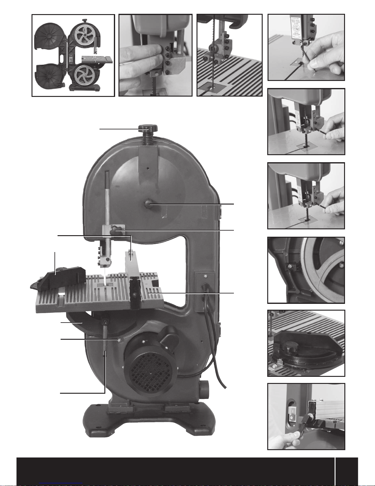
Table installation
1. Remove the Table Aligning Screw (6) and wing nut from the edge of the Work Table
(15), (Image I)
2. Remove the spring-loaded hex screw from the shaft of the Table Lock Handle (16)
(Image II), to release and remove the crank from the Table Lock Handle, (Image III)
3. Slide the Work Table (15) onto the Lower Blade Housing (8) by passing the blade
through the blade slot in the work table, (Image IV). Align the raised mounting rib,
(Image V) located on the side of the Lower Blade Housing, with the recess located on
the rear of the Table Angle Guide (18), (Image VI)
4. Slide the flat washer over the threaded end of the crank, (Image VII). Insert the
threaded end of the crank through the curved slot on the Table Angle Guide (18) and
screw into the threaded hole, (Image VIII). Tighten the screw until the mounting rib
fully engages with the recessed groove on the Table Angle Guide
5. Engage the Table Lock Handle (16) with the crank and fasten with the spring-loaded
hex screw, (Image IX)
Note: The Table Lock Handle (16) acts similarly to a ratchet mechanism and it can be
loosened by turning anti-clockwise. Pulling back on the handle, in the direction of the
spring-loaded hex screw, releases its engagement to the threaded crank, allowing quick
effortless Work Table (15) adjustment.
6. Replace the Table Aligning Screw (6) and wing nut, (Image I)
7. If necessary, adjust the Table Angle Guide (18) to reflect the actual table tilt position
in degrees
Mounting bandsaw to work stand
WARNING: ALWAYS make sure your bandsaw is securely mounted to a work bench or
an approved work stand. Motor vibration, weight on the work table and other factors may
cause the bandsaw to tip over, slide or walk along the work stand surface during operation.
Failure to do so could result in an accident, resulting in possible serious personal injury.
• The bandsaw must be securely fastened by the four base holes to a work stand or
workbench with heavy duty fasteners (not included). This prevents the bandsaw from
tipping over, sliding or walking/creeping along the work stand/workbench surface
during operation
Blade tension
• When the blade is centred on the upper and lower blade wheels, turn the Blade
Tension Adjustment Knob (12) clockwise until the spring begins to compress. Continue
tightening until the blade is tight on the upper and lower blade wheels
• Ensure the blade is tight so that it will not slip on the wheels, but do not over-tighten
Blade tracking
NOTE: Set the blade tension BEFORE making any tracking adjustments. Check that the
blade guides are not touching the blade.
• By hand, turn the upper blade wheel clockwise and watch the blade position on the
surface of the wheel. If the blade deviates from the centre, tracking adjustment is
required
• If the blade moves towards the outside edge of the blade wheel, turn the Tracking
Adjustment Knob (13) clockwise. Continue adjusting until the blade returns to and
remains in the centre of the blade wheel
• If the blade moves towards the inside edge of the blade wheel, turn the Tracking
Adjustment Knob anti-clockwise. Continue adjusting until the blade returns to and
remains in the centre of the blade wheel
• Check the position of the blade on the lower wheel. If the tracking is off, continue to
adjust the Tracking Adjustment Knob until the blade is centred on both blade wheels
as they rotate
Adjusting the upper blade guide stabilising bars and blade
guide bracket
Note: The upper and lower blade guides and support bearings stabilise the moving blade
during operation under load conditions. These guides MUST be checked and adjusted
BEFORE EACH USE and AFTER BLADE CHANGES.
Note: The Blade Guard (3) will need to be removed in order to perform this task. See
‘Replacing the blade’ for detailed instructions on how to remove the Blade Guard.
• Be especially careful when cutting wood and metal. Sparks from metal cutting are a
common cause of wood dust fires
• Where possible, use a dust extraction system to ensure a safer working environment
Bandsaw Safety
WARNING: Do not use saw bands which are damaged, excessively worn or deformed.
Doing so could cause the band to rupture, and be projected in the area of the operator.
WARNING: Do not operate the bandsaw, when the guarding protecting the saw band is
open. The saw band mechanism is dangerous when in motion.
WARNING: Do not attempt to clean the saw band when it is in motion. If tool cleaning Is
required, switch off the machine and wait for the saw to stop moving before commencing
cleaning procedures.
WARNING: Always ensure the blade guard is fully down during transportation. An exposed
saw blade is dangerous, and could potentially harm the operator or bystanders during
transportation.
WARNING: Do not use a bandsaw with a worn table insert. The table insert provides
support to the workpiece local to the cut, a worn table insert will give inadequate support.
WARNING: Never use the guards for holding during transportation. Hold the bandsaw at a
structurally reinforced area, that is suitable for holding during transportation.
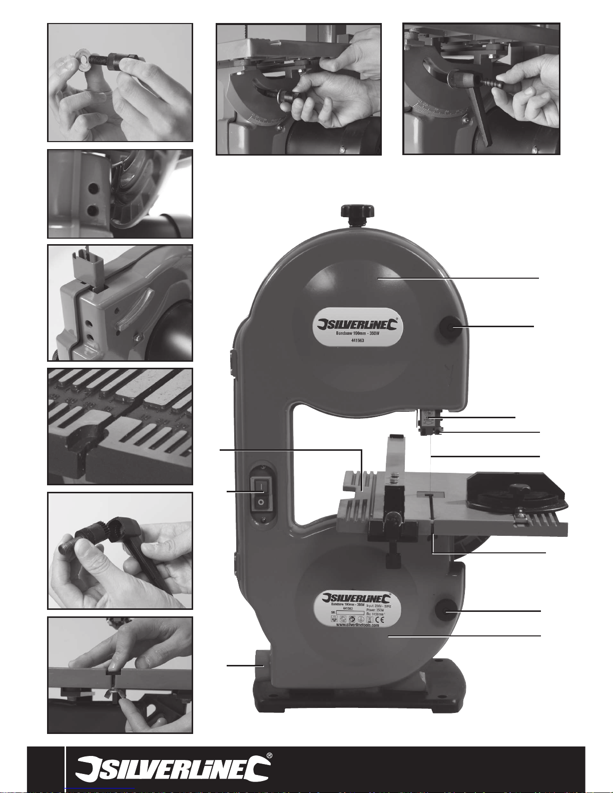
1 Upper Blade Housing
2 Upper Cover Knob
3 Blade Guard
4 Blade Guide
5 Blade
6 Table Aligning Screw
7 Lower Cover Knob
8 Lower Blade Housing
9 Sawdust Ejection Port
10 On/Off Switch
11 Table Level Calibration Screw
12 Blade Tension Adjustment Knob
13 Tracking Adjustment Knob
14 Blade Guard Adjusting Knob
15 Work Table
16 Table Lock Handle
17 Angle Guide
18 Tilt Scale
19 Mitre Gauge
20 Fence
Product Familiarisation
Page 10

www.silverlinetools.com
7
Bandsaw 190mm441563
• Loosen the two blade guide adjusting screws, with a hex key, see image (XIII) . Slide
each blade guide stabilising bar towards the Blade (5) so that they are as close as
possible to the blade, but without touching or pinching the blade. Tighten the two blade
guide adjusting screws securely with the hex key
• Loosen the blade guide bracket adjusting screw with the hex key, (Image XIV). Move the
bracket in or out until the front of the two blade guide stabilising bars are to the rear of,
and not touching, the blade teeth
• Retighten the blade guide bracket adjusting screw securely with the hex key, (Image
XIV)
• Refit the Blade Guard (3) if no additional adjustments are required
WARNING: ENSURE that the two blade guide stabilising bars do NOT touch the teeth of the
saw blade when you are operating the bandsaw and applying pressure into the saw blade
with your workpiece.
Adjusting the upper blade support bearing
Note: The Blade Guard (3) will need to be removed in order to perform this task. See
‘Replacing the blade’ for detailed instructions on how to remove the Blade Guard.
1. The blade support bearing keeps the saw Blade (5) from being pushed back when
cutting. This support bearing should be fixed 3mm behind the blade
2. Loosen the Blade Support bearing adjustment screw with the hex key, (Image XV).
Position the blade support bearing 3mm behind the smooth, rear edge of the blade
3. Tighten the support bearing adjustment screw securely with the hex key, (Image XV)
4. Refit the Blade Guard (3) if no additional adjustments are required
Adjusting the lower blade guide stabilising bars, blade guide
and support bearing
• Access to the lower blade guide stabilising bars, blade guide and support bearing,
requires opening the Lower Blade Housing (8)
• Follow the same steps and sequence used when adjusting the upper blade guide
stabilising bars for adjusting the lower blade guide and support bearing. See ‘Adjusting
the upper blade guide stabilising bars and blade guide bracket’, for detailed instructions
on adjustment
• To access the blade guide adjusting screw and support bearing adjusting screw, pass
the hex key through the holes in the lower blade wheel housing
NOTE: Make sure you have properly adjusted both the upper and lower blade guides. The
blade will be damaged if the blade teeth hit the blade guides.
Squaring the table to the blade
1. Raise the Blade Guard (3) as far as it will go
2. Loosen the Table Lock Handle (16)
3. Set a combination square on the table and align it with the blade
4. Move the Work Table (15) until it is at a 90° angle to the Blade (5). Tighten the Table
Lock Handle (16)
5. Turn the Table Level Calibration Screw (11) until it touches the frame
6. Recheck the adjustment. Zero the Angle Guide (17) to the correct marking on the
Table Angle Guide (18)
Sawdust ejection port
Note: It is necessary to connect a dust extraction device to the bandsaw, especially when
sawing wood, as dust particles can be harmful.
• The Sawdust Ejection Port (9) blows dust away from the user and the work area
• The opening of the Sawdust Ejection Port measures 1-¼" and may be connected to a
standard wet/dry workshop vacuum system
Operation
WARNING: ALWAYS wear eye protection, adequate respiratory and hearing protection, as
well as suitable gloves, when working with this tool.
WARNING: To prevent personal injury, ALWAYS disconnect the plug from the power source
when making any adjustment.
Switching on and off
WARNING: Before connecting the tool to a power source, make sure that all fasteners and
adjustment screws are tightly secured.
WARNING: To avoid possible injury, keep the blade wheel housing cover closed, secured in
place and in proper working order while the tool is in operation.
1. Locate the On/Off Switch (10), on the side of the hinged housing cover
2. To switch the bandsaw ‘On’ press the green ‘I’ button
3. To switch the bandsaw ‘Off’ press the red ‘O’ button
Using the mitre gauge
• The Mitre Gauge (19) can be turned 45° left or right
• To set the angle, loosen the lock knob on the mitre gauge and rotate the Mitre Gauge
until it reaches the desired angle on the angle gauge (Image XVII)
• Retighten the lock knob
Using the fence
• To fit the Fence (20) to the table loosen the locking lever by turning it anti-clockwise. Fit
the fence in the desired location on the Work Table (15), and fasten the fence by pushing
the lever down, (Image XVIII)
• Use a combination square to ensure that the fence is entirely parallel, or perpendicular
to the blade, and fasten securely
Tilting the work table
1. Loosen the Table Lock Handle (16)
2. Tilt the work table until it reaches the required angle
3. Check the angle on the Angle Guide (17). Tighten the work table lock handle
Making a cut
WARNING: To avoid blade contact and personal injury, adjust the Blade Guard (3) so that it
just clears the upper surface of the workpiece.
WARNING: Blade teeth are sharp. Always wear suitable protection, such as cut-resistant
gloves, and take care when handling a bandsaw blade.
WARNING: This bandsaw is only designed to cut workpieces that can be adequately
supported using the attached Work Table (15). Do not attempt to cut workpieces that
cannot be securely supported by the Work Table.
Note: When cutting with the table at an angle other than 90° to the blade, always use the
Fence (20) on the lower side of the table.
• For general cutting, follow the pattern lines by pushing and turning the workpiece at
the same time
• To achieve a curved radius cut, follow the pattern line with the blade while turning the
workpiece. The blade should cut in the middle of the pattern line
• Use both hands to feed the work through the blade
• Make sure you hold the workpiece firmly against the work table
• Use light forward pressure and do not force the workpiece against the bandsaw table
• When cutting small workpieces that have insufficient area to hold, or do not protrude
over the edge of the Work Table (15), use the provided push-stick to feed the workpiece
into the blade
Note: Always keep the push-stick nearby, so that it is readily available for use whilst
cutting and keep the push-stick away from the any conflict with blade.
Accessories
• A range of accessories and consumables, including 6tpi (633924), 10tpi (868739), and
14tpi (675295) Bandsaw blades, are available from your Silverline stockist. Spare parts
can be obtained from toolsparesonline.com
Maintenance
WARNING: ALWAYS disconnect from the power supply before carrying out any inspection,
maintenance or cleaning.
WARNING: DO NOT attempt to modify this tool or create accessories not recommended
for use with this tool. Any such alteration or modification is a misuse and could result in a
hazardous situation, leading to possible serious personal injury.
Replacing the blade
Note: Always use a saw blade that is compatible with the type of material being cut, for
most effective, and efficient cutting.
Note: The blade length for this bandsaw is 1425mm (56 1⁄4").
1. Unscrew the Upper Cover Knob (2) and Lower Cover Knob (7) of the hinged housing
cover, to reveal the internal bandsaw mechanism (Image X)
2. Loosen the Blade Guard Adjusting Knob (14) and position the Blade Guard (3) halfway
above the table. Tighten the Blade Guard Adjusting Knob (14)
3. Loosen the two blade guard mounting screws (Image XI) with a hex key and remove
the Blade Guard (3)
4. Remove the Table Aligning Screw (6) from the work table (Image I)
5. Turn the Blade Tension Adjustment Knob (12) anti-clockwise to release blade tension
and remove the old blade
6. Slide the old blade off the upper and lower Blade Wheels, and through the table slot
7. Guide the new blade through the blade slot, (Image IV) and on to the Blade Wheels.
Ensure that the blade is pointing outwards, with the teeth facing downwards (Image
XII)
8. Centre the blade on the soft, non-slip surface of the upper and lower Blade Wheels,
see ‘Blade tracking’ for detailed instructions on blade alignment
9. Rotate the wheels clockwise to help guide and centre the blade on the blade wheels
Replacing the table insert
• When worn, the table insert can be removed and replaced
• To remove the table insert, remove the Phillips head screw securing the table insert to
the Work Table (15). Then remove and replace
Page 11

8
GB
Wheel brush
• The wheel brush is located inside the housing (Image XVI) and helps keep the blade
and the wheel free of sawdust and wood chips
• To adjust, loosen the screw and position the wheel brush so that it contacts the bristles
of the brush
• Retighten the screw
General inspection
• Regularly check that all the fixing screws are tight
• Inspect the supply cord of the tool, prior to each use, for damage or wear. Repairs
should be carried out by an authorised Silverline service centre. This advice also applies
to extension cords used with this tool
Cleaning
• Keep your tool clean at all times. Dirt and dust will cause internal parts to wear quickly,
and shorten the machine’s service life. Clean the body of your machine with a soft
brush, or dry cloth. If available, use clean, dry, compressed air to blow through the
ventilation holes
• Clean the tool casing with a soft damp cloth using a mild detergent. Do not use alcohol,
petrol or strong cleaning agents
• Never use caustic agents to clean plastic parts
Lubrication
• Slightly lubricate all moving parts at regular intervals with a suitable spray lubricant
Storage
• Store this tool carefully in a secure, dry place out of the reach of children
Disposal
Always adhere to national regulations when disposing of power tools that are no longer
functional and are not viable for repair.
• Do not dispose of power tools, or other waste electrical and electronic equipment
(WEEE), with household waste
• Contact your local waste disposal authority for information on the correct way to
dispose of power tools
Problem Possible cause Solution
No function when On/Off
Switch (10) is operated
No power Check power supply
Defective On/Off Trigger Switch
Replace the On/Off Trigger Switch at an authorised Silverline service
centre
Inaccurate cut
Blade alignment off Re-align the saw blade as specified in ‘Blade tracking’
Worn saw blade Replace saw blade
Blade guide calibration is incorrect
Follow the instructions for blade guide calibration in ‘Adjusting the
upper blade guide stabilising bars and blade guide bracket’
Difficulty making straight cuts
Fence (20) is not parallel to the saw blade Re-align the Fence (20) as instructed in ‘Using the fence’
Blade guide calibration is incorrect
Follow the instructions for blade guide calibration in ‘Adjusting the
upper blade guide stabilising bars and blade guide bracket’
Troubleshooting
Page 12

www.silverlinetools.com
9
441563 Bandsaw 190mm
Notified body: TÜV Rheinland Co., Ltd.
The technical documentation is kept by: Silverline Tools
Date: 11/08/14
Signed:
Mr Darrell Morris
Managing Director
Name and address of the manufacturer:
Powerbox International Limited, Company No. 06897059. Registered address:
Central House, Church Street, Yeovil, Somerset BA20 1HH,
United Kingdom.
Terms & Conditions
Silverline Tools Guarantee
This Silverline product comes with a 3 year guarantee
Register this product at www.silverlinetools.com within 30 days of purchase
in order to qualify for the 3 year guarantee. Guarantee period begins
according to the date of purchase on your sales receipt.
Registering your purchase
Registration is made at silverlinetools.com by selecting the Guarantee
Registration button. You will need to enter:-
• Your personal details
• Details of the product and purchase information
Once this information is entered your guarantee certificate will be created in
PDF format for you to print out and keep with your purchase.
Guarantee period becomes effective from the date of retail purchase as
detailed on your sales receipt.
PLEASE KEEP YOUR SALES RECEIPT
If this product develops a fault within 30 days of purchase, return it to the
stockist where it was purchased, with your receipt, stating details of the fault.
You will receive a replacement or refund.
If this product develops a fault after the 30 day period, return it to:
Silverline Tools Service Centre
PO Box 2988
Yeovil
BA21 1WU, UK
The guarantee claim must be submitted during the guarantee period.
You must provide the original sales receipt indicating the purchase date, your
name, address and place of purchase before any work can be
carried out.
You must provide precise details of the fault requiring correction.
Claims made within the guarantee period will be verified by Silverline Tools
to establish if the deficiencies are related to material or manufacturing of
the product.
Carriage will not be refunded. Items for return must be in a suitably clean and
safe state for repair, and should be packaged carefully to prevent damage or
injury during transportation. We may reject unsuitable or
unsafe deliveries.
All work will be carried out by Silverline Tools or its authorized
repair agents.
The repair or replacement of the product will not extend the period
of guarantee
Defects recognised by us as being covered by the guarantee shall be
corrected by means of repair of the tool, free of charge (excluding carriage
charges) or by replacement with a tool in perfect working order.
Retained tools, or parts, for which a replacement has been issued, will
become the property of Silverline Tools.
The repair or replacement of your product under guarantee provides benefits
which are additional to and do not affect your statutory rights as a consumer.
What is covered:
The repair of the product, if it can be verified to the satisfaction of Silverline
Tools that the deficiencies were due to faulty materials or workmanship
within the guarantee period.
If any part is no longer available or out of manufacture, Silverline Tools will
replace it with a functional replacement part.
Use of this product in the EU.
What is not covered:
Silverline Tools does not guarantee repairs required as a result of:
Normal wear and tear caused by use in accordance with the operating
instructions eg blades, brushes, belts, bulbs, batteries etc.
The replacement of any provided accessories drill bits, blades, sanding
sheets, cutting discs and other related items.
Accidental damage, faults caused by negligent use or care, misuse, neglect,
careless operation or handling of the product.
Use of the product for anything other than normal domestic purposes.
Change or modification of the product in any way.
Use of parts and accessories which are not genuine Silverline Tools
components.
Faulty installation (except installed by Silverline Tools).
Repairs or alterations carried out by parties other than Silverline Tools or its
authorized repair agents.
Claims other than the right to correction of faults on the tool named in these
guarantee conditions are not covered by the guarantee.
Battery Guarantee
Silverline batteries are guaranteed for 30 days. If a defect occurs on a
registered battery during the term of the Battery Guarantee, due to material
or manufacturing fault, then Silverline will replace it free of charge. This
guarantee does not apply to commercial use nor does it extend to normal
wear and tear or damage as a result of accident, abuse or misuse.
CE Declaration of Conformity
The undersigned: Mr Darrell Morris
as authorised by: Silverline Tools
Declares that
Identification code: 441563
Description: Bandsaw 190mm
Conforms to the following directives and standards:
• Machinery Directive 2006/42/EC
• Low Voltage Directive 2006/95/EC
• EMC Directive 2004/108/EC
• RoHS Directive 2011/65/EU
• EN61029-1:2009+A11
• EN61029-2-5:2011
• EN55014-2+A2:2008
• EN55014-1:2006+A1:2009
• EN61000-3-2:2006+A1:2009+A2:2009
• EN61000-3-3:2008
Page 13
10
F
Attention : Toujours porter des protections sonores lorsque le niveau d’intensité est
supérieur à 85 dB(A) et limiter le temps d’exposition si nécessaire. Si l’intensité sonore
devient inconfortable, même avec les protections, arrêter immédiatement d’utiliser
l’appareil, vérifier que les protections soient bien mises et qu’elles soient adéquates avec
le niveau sonore produit par l’appareil.
Attention : L’exposition de l’utilisateur aux vibrations peut engendrer une perte du toucher,
des engourdissements, des picotements et ainsi réduire la capacité de préhension. De
longues expositions peuvent également provoquer ces symptômes de façon chronique.
Si nécessaire, limiter le temps d’exposition aux vibrations, et porter des gants antivibrations. Ne pas utilisez cet appareil avec vos mains sous des conditions en dessous
de températures normales, car l’effet vibratoire en est accentué. Se référer au cas de
figures des caractéristiques relatives aux vibrations pour calculer le temps et fréquence
d’utilisation de l’appareil.
Les niveaux sonores et vibratoires des caractéristiques techniques sont déterminés
en fonction de la norme EN60745 ou autres normes internationales. Ces données
correspondent à un usage normale de l’appareil, et ce dans des conditions de travail
normales. Un appareil mal entretenu, mal assemblé ou mal utilisé peut augmenter les
niveaux sonores et vibratoires. Pour plus d’informations sur la directive des émissions
sonores et vibratoires, visitez le site http://osha.europa.eu/fr.
CONSIGNES GÉNÉRALES DE
SÉCURITÉ RELATIVES AUX
APPAREILS ÉLECTRIQUES
Attention : Veuillez lire l’intégralité des consignes de sécurité et des instructions. Le
non-respect de ces consignes et instructions peut entraîner un risque de choc électrique,
d’incendie et/ou se traduire par des blessures graves.
Attention : Cet appareil n’est pas conçu pour être utilisé par des personnes (enfants
compris) ayant des capacités physiques ou mentales réduites, ou n’ayant pas la
connaissance ou l’expérience requise, à moins d’être sous la supervision d’une personne
responsable de leur sécurité ou d’avoir reçu les instructions nécessaires. Les enfants ne
doivent pas s’approcher et jouer avec cet appareil.
Avertissement : Utiliser l’appareil électrique, les accessoires et outils à monter
conformément à ces instructions, en tenant compte des conditions de travail et de la
tâche à réaliser. Toute utilisation d’un appareil électrique autre que celle pour laquelle il a
été conçu peut entraîner des situations à risque.
L’expression « appareil électrique » employée dans les présentes consignes recouvre aussi
bien les appareils filaires à brancher sur le secteur que les appareils sans fils fonctionnant
sous batterie.
1. Maintenir une zone de travail propre - Des zones encombrées et mal éclairées
sont sources d’accidents.
2. Prendre en compte la zone de travail
- Ne pas exposer les outils à la pluie
- Ne pas utiliser les outils dans des endroits humides
Description des symboles
La plaque signalétique figurant sur votre outil peut présenter des symboles. Ces symboles
constituent des informations importantes relatives au produit ou des instructions
concernant son utilisation.
Port de protection auditive
Port de lunettes de sécurité
Port de masques respiratoires
Port du casque
Port de gants
Lire le manuel d’instruction
NE PAS utiliser sous la pluie ou un environnement humide!
Pour usage intérieur uniquement
Construction de classe I (Mise à la terre)
Attention !
ATTENTION : les pièces mobiles peuvent engendrer des écrasements et
des coupures.
Conforme à la réglementation et aux normes de sécurité pertinentes
Protection de l’environnement
Les produits électriques usagés ne doivent pas être jetés avec les ordures
ménagères. Veuillez les recycler dans les centres prévus à cet effet. Pour
de plus amples informations, veuillez contacter votre municipalité ou point
de vente.
V Volts
~ Courant alternatif
A Ampère
n
o
Vitesse à vide
Hz Hertz
W, kW Watt, kilowatt
/min or min
-1
tour par minute
Caratéristiques techniques
Tension : ........................................................ 230 V~ 50 Hz
Puissance : .................................................... 350 W
Profondeur de coupe :.................................... 190 mm
Longueur du ruban de scie : .......................... 1425 mm
Capacité de coupe : ....................................... 80 mm
Dimensions de la table :................................. 300 x 300 mm
Classe de protection: .....................................
Informations sur le niveau d’intensité sonore et vibratoire :
Pression acoustique LPA:.................................86,3 dB(A)
Puissance acoustique LWA: ............................. 99,3 dB(A)
Incertitude K : ................................................ 3 dB
L’intensité sonore peut dépasser 85 dB(A) et il est recommandé que l’opérateur
prenne des mesures de protection sonore.
Du fait de l’évolution constante de nos produits, les caractéristiques des produits
Silverline peuvent changer sans notification préalable.
Traductions des instructions originales
Page 14

21. Ne faire réparer votre appareil électrique que par un réparateur qualifié. Cet
appareil est conforme aux normes de sécurité en vigueur. Cela permet de maintenir
la sécurité d’utilisation de l’appareil électrique et d’éviter des risques considérables
pour l’utilisateur.
Attention : utiliser uniquement des pièces de rechange identiques.
Attention : Si le câble d’alimentation est endommagé, le faire remplacer par un centre
agrée.
22. La prise d’un appareil électrique doit être adaptée à la prise du secteur. Ne
jamais modifier la prise en aucune façon. Ne jamais utiliser d’adaptateur sur la prise
électrique d’appareil mis à la terre. Des prises non modifiées, adaptées aux boîtiers
de prise de courant, réduiront le risque de décharge électrique.
23. Si une utilisation de l’appareil électrique dans un environnement humide
ne peut être évitée, utiliser une alimentation protégée par un disjoncteur
différentiel. L’utilisation d’un disjoncteur différentiel réduit le risque de décharge
électrique.
NOTE: The term “residual current device (RCD)” may be replaced by the term “ground fault
circuit interrupter (GFCI)” or “earth leakage circuit breaker (ELCB)”.
Prises polarisées (Uniquement pour les pays de l’Amérique du nord). Pour réduire les
risques de chocs électriques, cet appareil comporte une prise polarisée (une des fiches
est plus large que l’autre). Cette prise se branche dans une prise de courant polarisée
uniquement dans un sens. Si la prise ne rentre pas complètement, inverser la prise.
Sinon, contacter un électricien qualifié pour installer une prise de courant adaptée. Ne pas
changer la prise de l’appareil.
Consignes de sécurité relatives
aux outils de coupe
AVERTISSEMENT : avant de brancher l’outil sur l’alimentation secteur, vérifiez bien que la
tension d’alimentation soit la même que celle indiquée sur la plaque signalétique de l’outil.
Une alimentation électrique dont la tension est supérieure à celle indiquée sur l’outil risque
d’entraîner des blessures chez l’utilisateur et des dommages sur l’outil. En cas de doute,
ne branchez pas l’outil. L’utilisation d’une source de courant dont la tension est inférieure à
celle indiquée sur l’outil peut endommager le moteur
Utilisation du bon outil de coupe
• Assurez-vous que votre outil de coupe convient au travail entrepris. Référez-vous
toujours à la notice d’informations, ne présumez pas qu’un outil est approprié à la tâche
sans faire de vérification préalable.
Protection oculaire
• Portez toujours des protections oculaires appropriées lors de l’utilisation d’outils de
coupe.
• Les lunettes ordinaires n’ont pas pour fonction de fournir une protection efficace
à l’utilisation de ce produit. Des verres normaux ne résistent pas aux impacts et
pourraient voler en éclats.
Protection auditive
• Portez toujours des protections auditives appropriées lorsque le niveau sonore dépasse
85 dB.
Protection respiratoire
• Assurez-vous de porter, ainsi que toute personne à proximité, un masque anti-poussière
approprié.
Tenez compte des personnes autour de vous
• Il relève de l’utilisateur de s’assurer que les personnes se trouvant à proximité de la
zone de travail ne soient pas exposées à des niveaux sonores dangereux ou à des
concentrations de poussières dangereuses et sont pourvues de dispositifs de protection
appropriés.
Objets cachés
• Avant d’effectuer une coupe, vérifiez qu’il ne se trouve aucun corps étranger dans la
pièce de travail.
• Ne coupez aucun matériau comportant des corps étrangers à moins d’être certain que
l’accessoire installé sur votre appareil convient à ce travail.
• Des fils électriques et des tuyaux peuvent être dissimulés dans les murs, des durites de
carburant peuvent être dissimulées dans les panneaux de carrosserie et l’herbe haute
peut dissimuler des pierres et du verre. Vérifiez toujours minutieusement votre zone de
travail avant de commencer la coupe.
Attention aux projections de débris
• Dans certains cas, des débris peuvent être projetés à grande vitesse de l’outil de coupe.
Assurez-vous qu’il ne se trouve aucune autre personne à proximité de la zone de travail.
Si la présence d’autres personnes à proximité de la zone de travail est nécessaire,
l’utilisateur a la responsabilité de s’assurer qu’elles soient munies d’équipements de
protection appropriés.
Installation d’accessoires de coupe
• Assurez-vous que les accessoires de coupe soient correctement et solidement installés
avant utilisation et que toute clé ou tout outil de réglage ait été retiré.
• Utilisez uniquement des accessoires de coupe recommandés pour votre appareil.
• N’effectuez aucune modification sur l’accessoire.
www.silverlinetools.com
11
441563
- Travailler dans une zone bien éclairée
- Ne pas utiliser d’outils électriques dans des environnements explosifs, tels qu’à
proximité de liquides, de gaz ou de poussières inflammables
3. Eviter les décharges électriques : Eviter le contact corporel avec les surfaces
mises à la terre telles que tuyaux, radiateurs, cuisinières et réfrigérateurs
4. Eloigner les personnes aux alentours. Ne laisser aucune personne dont la
présence n’est pas nécessaire, surtout les enfants, s’approcher de la zone de travail
et d’être en contact avec l’appareil.
5. Ranger les appareils électriques inutilisés dans un endroit sûr et sec, et hors
de portée des enfants
6. Ne pas forcer sur l’appareil électrique. Un appareil électrique adapté et employé
au rythme pour lequel il a été conçu permettra de réaliser un travail de meilleure
qualité et dans de meilleures conditions de sécurité
7. Utiliser l’appareil électrique approprié au travail à effectuer. Ne pas utiliser de
petits outils pour de lourdes tâches.
8. Porter des vêtements appropriés.
- Ne pas porter de vêtements amples ou des bijoux pendants qui peuvent être
happés par les pièces en rotation.
- Le port de chaussures antidérapantes est recommandé en extérieur.
- Attacher ou protéger les cheveux longs
9. Porter un équipement de protection approprié.
- Toujours porter une protection oculaire.
- Toujours porter un masque à poussières lors de travaux créant de la poussière.
Attention : Ne pas porter les équipements de protection ou les vêtements appropriés peut
engendrer et aggraver des blessures.
10. Brancher un système d’extraction de la poussière : Si l’appareil est pourvu de
dispositifs destinés au raccord d’équipements d’extraction et de récupération de la
poussière/sciure, s’assurer qu’ils soient bien fixés et utilisés correctement.
11. Ne pas maltraiter le cordon électrique. Ne jamais utiliser le cordon électrique
pour porter, tirer ou débrancher l’appareil. Protéger le cordon électrique de la chaleur,
du contact avec l’essence, des bords tranchants et pièces rotatives. Un cordon
électrique endommagé ou entortillé accroît le risque de décharge électrique.
12. Sécuriser votre travail. Si possible, utiliser des serre-joints ou un étau pour
maintenir la pièce de travail. C’est plus sûr et efficace que de tenir avec la main.
13. Ne pas essayer d’atteindre une zone hors de portée. Se tenir toujours en position
stable permettant de conserver l’équilibre.
14. Veiller à l’entretien des appareils électriques.
- Veiller à ce que les outils de coupe soient tenus affûtés et propres
- Suivre les instructions de lubrification et de changement des accessoires
- Vérifier régulièrement les câbles et les faires réparer /remplacer par un centre
agrée.
- Vérifier également l’état des rallonges utilisées.
- Travailler avec des mains propres (sans graisse ni huile) et sèches
Attention : De nombreux accidents sont dus à l’utilisation d’appareils électriques mal
entretenus
15. Débrancher l’appareil électrique. Lorsque l’appareil n’est pas utilisé, ou avant
toute opération d’entretien ou de changement d’accessoires, veiller à débrancher
l’appareil de sa source d’alimentation.
Attention : utiliser des accessoires non recommandés par le fabricant peut engendrer
des blessures.
16. Enlever les clés et outils de réglage. Prendre l’habitude de retirer ces outils
avant de mettre l’appareil en marche.
17. Eviter tout démarrage accidentel ou intempestif. S’assurer que l’interrupteur
marche-arrêt soit en position d’arrêt avant de brancher l’appareil sur l’alimentation
secteur ou d’installer la batterie, de prendre l’appareil ou de le transporter.
Attention : Des démarrages accidentels peuvent être dangereux.
18. Usage en extérieur : Lors d’une utilisation de l’appareil électrique en extérieur, se
servir d’une rallonge appropriée à une utilisation en extérieur. Cela réduit le risque
de décharge électrique
19. Rester vigilent et faire preuve de bon sens lors de la manipulation de l’appareil.
Ne pas utiliser un appareil électrique lorsque l’on se trouve dans un état de fatigue, ou
sous l’influence de drogues, d’alcool ou de médicaments.
Attention : Un moment d’inattention pendant l’utilisation d’un outil électrique peut se
traduire par des blessures graves
20. Inspecter les pièces endommagées
- Avant d’utiliser un appareil, toujours vérifier qu’il soit en bon état de marche
- Vérifier que les éléments rotatifs soient bien alignés et non grippés. S’assurer
de l’absence de pièces cassées ou endommagées susceptibles de nuire au bon
fonctionnement de l'appareil
- Une protection ou partie défectueuse doit être réparée ou remplacée par un centre
agrée, sauf en cas d’indication du manuel.
- Les interrupteurs défectueux doivent être remplacés par un centre agrée.
Attention : Ne pas utiliser un appareil électrique dont la commande ne s’effectue plus par
l’interrupteur marche-arrêt. Il est dangereux et doit être réparé.
Scie à ruban 190 mm
Page 15

12
F
Usage conforme
Scie à ruban Silverline 3550 W montée sur établi à moteur à induction avec table intégrale
inclinable pour permettre des coupes d’onglet jusqu’à 45°. Elle peut être utilisée pour
effectuer des coupes irrégulières et des coupes arrondies dans le bois, le plastique et les
métaux légers et doux uniquement.
Déballage
• Déballez le produit avec soin. Veillez à retirer tout le matériau d’emballage et
familiarisez-vous avec toutes les caractéristiques du produit.
• Si des pièces sont endommagées ou manquantes, faites-les réparer ou remplacer avant
d’utiliser l’appareil.
Avant utilisation
ATTENTION : Assurez-vous que l’appareil soit débranché de sa source d’alimentation
avant d’installer ou changer d’accessoires, ou faire des réglages.
Installation du plan de travail
1. Enlevez la vis d’alignement du plan de travail (6) et l’écrou à oreilles de l’extrémité
du plan de travail (15). (Image I).
2. Enlevez la vis hexagonale à ressort de l’arbre de la poignée de verrouillage du plan
de travail (16)(Image II) pour libérer le vilebrequin de la poignée de verrouillage du
plan de travail.(Image III)
3. Faites coulisser le plan de travail (15)sur le carter inférieur du ruban (8) en faisant
passer le ruban à travers la fente de passage (Image IV)prévue dans le plan de
travail. Assurez-vous que la nervure de montage (Image IV), située sur le côté
du carter inférieur du ruban, s’emboîte dans la rainure du support de l’échelle
d’inclinaison (18) du plan de travail.(Image VI).
4. Faites glisser la rondelle plate sur l’extrémité filetée du vilebrequin (Image VII).
Introduisez l’extrémité filetée du vilebrequin dans la fente incurvée du support de
l’échelle d’inclinaison (18) et dans l’orifice taraudé (Image VIII). Serrez la vis jusqu’à
ce que la nervure de montage s’emboîte complètement dans la rainure située sur le
support de l’échelle d’inclinaison.
5. Assemblez la poignée de verrouillage de la table(16) et le vilebrequin et fixez-les à
l’aide de la vis hexagonale à ressort (Image IX).
Se familiariser avec le produit
1 Carter supérieur du ruban
2 Molette du carter supérieur
3 Protection du ruban
4 Guide du ruban
5 Ruban
6 Vis d’alignement du plan de travail
7 Molette du carter inférieur
8 Carter inférieur du ruban
9 Sortie d’extraction de la sciure
10 Interrupteur marche/arrêt
11 Vis de réglage de la mise de niveau de la table
12 Molette de réglage de la tension du ruban
13 Molette de réglage de l’alignement du ruban
14 Molette de réglage de la protection du ruban
15 Plan de travail
16 Poignée de verrouillage du plan de travail
17 Guide d’angle
18 Echelle d’inclinaisons du plan de travail
19 Guide d’onglets
20 Guide parallèle
Sens de coupe
• Faites avancer la pièce de travail vers la lame ou la fraise, et ce à l’encontre du
mouvement de la lame ou de la fraise.
Attention à la chaleur
• Sachez que les outils de coupe ainsi que les pièces de travail peuvent chauffer pendant
l’utilisation de l’appareil. Ne tentez pas de changer d’accessoire tant que l’appareil n’a
pas complètement refroidi.
Contrôle poussière /copeaux
• Ne laissez pas la poussière ou des copeaux de métal s’accumuler. La sciure constitue
un risque d’incendie et certains copeaux métalliques sont explosifs.
• Faites tout particulièrement attention lors de la coupe du bois ou du métal à l’aide de
machines électriques. Les étincelles provoquées par la coupe du métal sont une cause
courante d’incendie des poussières de bois.
• Lorsque cela est possible, utilisez un système d’extraction de la poussière pour assurer
un environnement de travail plus sûr.
Consignes de sécurité relatives
aux scies à ruban
ATTENTION : N’utilisez pas des rubans de scie qui sont endommagés, excessivement
usés ou déformés. Ne pas respecter cette consigne peut provoquer la rupture du ruban et
d’être projeté dans la zone de l’utilisateur.
ATTENTION : N’utilisez pas la scie à ruban lorsque le garde protégeant le ruban est ouvert.
Le mécanisme du ruban est dangereux lorsqu’il est en mouvement.
ATTENTION : N’essayez pas de nettoyer le ruban lorsqu’il est en mouvement. Si un
nettoyage de l’appareil est nécessaire, éteignez l’appareil et attendez que la scie soit
complètement arrêtée avant de commencer les procédures de nettoyage.
ATTENTION : Assurez-vous que le garde de protection de la lame soit complètement
abaissé lors d’un transport. Une lame de scie exposée est dangereuse, et peut
potentiellement blesser l’utilisateur ou les personnes qui sont autour lors du transport
de la scie.
ATTENTION : N’utilisez pas la scie à ruban avec un insert de table usé. L’insert de table
procure un support de la pièce de travail au niveau de la zone de coupe, par conséquent,
un insert de table usé procure un support inapproprié.
ATTENTION : N’utilisez jamais les gardes de protection pour maintenir la scie pendant
le transport. Tenez la scie par les zone de structures renforcées, qui sont adaptées le
transport de la scie.
Page 16

www.silverlinetools.com
13
441563
4. S’il n’est pas nécessaire d’effectuer d’autres réglages, remettez la protection du
ruban (3) en place.
Réglage des barres stabilisatrices du guide inférieur du
ruban, du guide inférieur du ruban et du galet inférieur de
support
• Pour accéder au guide inférieur du ruban, aux barres stabilisatrices du guide inférieur
du ruban et au galet inférieur de support, il est nécessaire d’ouvrir le carter inférieur
du ruban (8).
• Pour régler le guide inférieur du ruban et le galet inférieur de support, suivez les mêmes
étapes et séquences indiquées pour le réglage des barres stabilisatrices du guide
supérieur du ruban.
• Pour accéder à la vis de réglage du guide du ruban et à la vis de réglage du galet de
support, introduisez la clé mâle dans les orifices situés dans le carter inférieur de la
roue du ruban.
Remarque : assurez-vous d’avoir correctement réglé les guides supérieur et inférieur
du ruban. Le ruban sera abîmé si les dents du ruban entrent en contact avec les guides
du ruban.
Réglage du plan de travail à angle droit par rapport au ruban
1. Soulevez la protection du ruban (3) le plus haut possible.
2. Desserrez la poignée de verrouillage du plan de travail (16).
3. Placez une équerre sur le plan de travail et alignez-la avec le ruban.
4. Déplacez le plan de travail (15) jusqu’à ce qu’il soit à un angle de 90° par rapport au
ruban (5).Resserrez la poignée de verrouillage du plan de travail (16).
5. Faites tourner la vis de réglage de la mise de niveau de la table (11) jusqu’à ce
qu’elle entre en contact avec le cadre.
6. Revérifiez le réglage. Réglez à nouveau le guide d’angle (17) au relevé numérique
sur l’ échelle d’inclinaisons du plan de travail (18)
Sortie d’extraction de la sciure
Remarque : Il est nécessaire de brancher un appareil d’extraction de la poussière lors du
sciage du bois, car la poussière peut être nocive.
• La sortie d’extraction de la sciure (9) permet d’évacuer la sciure du plan de travail.
• L’orifice de la sortie d’expulsion de la sciure mesure 32 mm et permet le raccordement
d’un système d’aspiration sec/humide d’atelier.
Instructions d’utilisation
ATTENTION : Portez toujours des protections oculaires, des protections respiratoires et
auditives adéquates, ainsi que des gants appropriés lorsque vous utilisez cette appareil.
ATTENTION : Assurez-vous que l’appareil soit débranché de sa source d’alimentation
avant de faire des réglages.
Mise en marche/arrêt
ATTENTION : Avant de brancher l’appareil sur sa source d’alimentation, assurez-vous que
toutes les fixations et les réglages de vis soient bien fixées.
ATTENTTION : Pour éviter d’éventuelles blessures, gardez le couvercle du carter de la
roue du ruban fermée, bien en place et en condition de fonctionnement lorsque l’appareil
est en marche
1. Localisez l’interrupteur marche/arrêt (10) sur le côté à charnière du couvercle du
carter.
2. Pour mettre en marche la scie à ruban, appuyez sur le bouton vert ‘I’.
3. Pour arrêter, appuyez sur le bouton rouge ‘O’
Utilisation du guide d’onglets
• Le guide d’onglets (19) peut être orienté à 45°, à gauche ou à droite.
• Pour régler l’angle, desserrez la molette de verrouillage et faites tourner le guide
jusqu’à ce qu’il atteigne l’angle désiré sur l’échelle graduée (Image XVII).
• Resserrez la molette de verrouillage.
Utilisation du guide parallèle
• Le guide (20) à réglage rapide peut être déplacé sur le plan de travail et verrouillé en
place en soulevant (pour déverrouiller) ou en abaissant (pour verrouiller) la poignée de
verrouillage du guide (Image XVIII).
• Utilisez une équerre combinée pour s’assurer que le guide soit parfaitement parallèle,
ou perpendiculaire au ruban, et serrez bien.
Inclinaison du plan de travail
1. Desserrez la poignée de verrouillage du plan de travail (16).
2. Inclinez le plan de travail jusqu’à ce qu’il se trouve à l’angle requis.
3. Vérifiez les repères d’angle figurant en face du guide d’angle (17). Resserrez la
poignée de verrouillage du plan de travail.
Remarque : La poignée de verrouillage du plan de travail (16) s’enclenche lorsque
le vilebrequin est poussé vers la tête de la vis hexagonale à ressort pour verrouiller/
déverrouiller le plan de travail (15).
6. Remettez en place la vis d’alignement (6) et l’écrou à oreilles (voir Fig. 1).
7. Si nécessaire, réglez le guide d’angle (17) pour tenir compte de l’inclinaison réelle du
plan de travail (en degrés).
Assemblage de la scie à ruban sur le socle de travail
AVERTISSEMENT : assurez-vous TOUJOURS que votre scie à ruban soit bien fixée sur un
établi ou un socle de travail adéquat. Les vibrations du moteur, le poids exercé sur l’établi
ainsi que d’autres facteurs pourraient déséquilibrer la scie à ruban, la faire glisser ou la
faire se déplacer sur le socle de travail au cours de l’utilisation. Une mauvaise fixation de
la scie à ruban sur un établi pourrait entraîner un accident et provoquer des blessures
graves aux personnes.
• La scie à ruban doit être solidement fixée sur l’établi ou le socle de travail par les quatre
trous présents sur l’embase à l’aide de fixations très résistantes (non fournies). Cela
permet d’éviter le renversement, le glissement/déplacement de la scie à ruban sur la
surface de l’établi ou le socle de travail au cours de l’utilisation.
Tension du ruban
• Lorsque le ruban est centré sur les roues supérieure et inférieure du ruban (F), faites
tourner la molette de réglage de la tension du ruban (12) dans le sens des aiguilles
d’une montre jusqu’à ce que le ressort commence à être comprimé.
• Continuez de serrer jusqu’à ce que le ruban soit tendu sur les roues supérieure et
inférieure.
• Assurez-vous que le ruban soit tendu de sorte qu’il ne patine pas sur les roues, mais
ne le serrez pas trop fort.
Alignement du ruban
Remarque : réglez la tension du ruban AVANT d’effectuer tout réglage d’alignement.
Vérifiez que les guides du ruban ne soient pas en contact avec le ruban.
• Faites tourner à la main la roue supérieure du ruban dans le sens des aiguilles d’une
montre et vérifiez la position du ruban sur la surface de la roue. Si le ruban se déplace
d’un côté, il est nécessaire de régler l’alignement.
• Si le ruban se déplace vers la jante de la roue (H), faites tourner la molette de réglage de
l’alignement (13) dans le sens des aiguilles d’une montre. Continuez le réglage jusqu’à
ce que le ruban revienne et reste au centre de la roue du ruban.
• Si le ruban se déplace vers le rebord intérieur (J) de la roue du ruban, faites tourner
la molette de réglage de l’alignement (13) dans le sens inverse des aiguilles d’une
montre. Continuez le réglage jusqu’à ce que le ruban revienne et reste au centre de
la roue du ruban.
• Vérifiez la position du ruban sur la roue inférieure. Si le ruban n’est pas centré,
continuez de faire tourner la molette de réglage de l’alignement (13) jusqu’à ce que le
ruban soit centré sur les deux roues du ruban lorsqu’elles tournent.
Réglage des barres stabilisatrices supérieures du guide du
ruban et du support du guide du ruban
Remarque : les guides supérieur et inférieur du ruban et les galets de support stabilisent
le ruban en mouvement au cours de son utilisation sous charge. Ces guides DOIVENT être
vérifiés et réglés AVANT CHAQUE UTILISATION et APRÈS CHAQUE CHANGEMENT DE RUBAN.
Remarque : La protection du ruban(3) a besoin d’être enlevé afin d’effectuer cette tâche.
Voir ‘Remplacement du ruban’ pour les instructions relatives au retrait de la protection
du ruban.
• Desserrez les deux vis de réglage du guide du ruban (voir image XIII) au moyen d’une
clé mâle. Faites glisser chacune des barres stabilisatrices du guide du ruban vers le
ruban (5) afin qu’elles soient le plus près possible du ruban, mais sans le toucher ou le
serrer. Serrez bien les deux vis de réglage du guide du ruban à l’aide de la clé mâle.
• Desserrez la vis de réglage du support du guide du ruban (voir image XIV) au moyen
de la clé mâle. Faites avancer ou reculer ce support jusqu’à ce que la partie avant des
deux barres stabilisatrices du guide du ruban se trouve à l’arrière des dents du ruban,
et sans les toucher.
• Resserrez bien la vis de réglage du support du guide du ruban (Image XIV) au moyen
de la clé mâle.
• Replacez la protection du ruban s’il n’y a pas de réglages supplémentaires à effectuer
ATTENTION : ASSUREZ-VOUS que les deux barres stabilisatrices du guide du ruban
NE touchent PAS les dents du ruban pendant l’utilisation de la scie à ruban et pendant
l’application de pression contre le ruban avec votre pièce de travail
Réglage du galet supérieur de support du ruban
Remarque : La protection du ruban(3) a besoin d’être enlevé afin d’effectuer cette tâche.
Voir ‘Remplacement du ruban’ pour les instructions relatives au retrait de la protection
du ruban.
1. Le galet de support du ruban empêche le ruban (5) d’être poussé vers l’arrière
pendant la coupe. Ce galet de support devrait être fixé à 3 mm du dos du ruban.
2. Desserrez la vis de réglage du galet de support du ruban (Image XV) au moyen de
la clé mâle. Positionnez le galet du support du ruban (Image XV) à 3 mm derrière
l’extrémité arrière et lisse du ruban.
3. Resserrez bien la vis de réglage du galet de support du ruban (Image XV) à l’aide de
la clé mâle.
Scie à ruban 190 mm
Page 17

14
F
Effectuer une coupe
ATTENTION : pour éviter le contact avec le ruban et tout risque de blessures aux
personnes, réglez la protection supérieure (3) de sorte qu’elle touche presque la surface
supérieure de la pièce de travail.
ATTENTION: les dents du ruban sont coupantes. Portez toujours des gants de protection
adéquats, tels que des gants anti-coupures. Faites attention pendant la manipulation d’un
ruban de scie à ruban.
ATTENTION : Cette scie à ruban est seulement conçue pour effectuer des coupes sur des
pièces de travail qui peuvent être maintenues adéquatement sur le plan de travail (15).
Remarque : Lorsque vous effectuez des coupes sur la table qui a un angle autre que 90° avec
le ruban, utilisez toujours le guide (20) sur le côté le plus bas de la table.
• Pour les coupes d’ordre général, suivez le tracé préalablement effectué en poussant et
faisant tourner, en même temps, la pièce de travail. N’essayez pas de travailler sur des
pièces de travail qui ne peuvent pas être maintenues sur le plan de travail.
• Pour obtenir une coupe incurvée, suivez le tracé avec le ruban pendant que vous
tournez la pièce de travail. Le ruban devrait couper au milieu du tracé.
• Utilisez les deux mains pour faire avancer la pièce de travail contre le ruban.
• Assurez-vous de maintenir fermement la pièce de travail contre le plan de travail. Faites
avancer la pièce de travail en y appliquant une pression légère mais ne la faites pas
forcer contre le plan de travail de la scie à ruban.
• Pour des coupes sur les petites pièces de travail qui n’ont pas beaucoup d’espace de
prise, ou qui ne dépassent pas assez du plan de travail (1), utilisez un poussoir pour
amener la pièce de travail sur le ruban.
Remarque : Gardez toujours à disposition un poussoir, de sorte qu’il soit toujours
disponible lors d’une coupe, et gardez le poussoir éloigné du ruban pour éviter les contacts.
Accessoires
• Une gamme d’accessoires et de consommables, tels que des lames de scie à ruban
6 TPI (633924), 10 TPI (868739), et 14 TPI(675295), est disponible depuis votre
revendeur Silverline. Des pièces de rechanges peuvent être obtenues en ligne depuis
toolspareonline.com.
Entretien
ATTENTION : Assurez-vous que l’appareil soit débranché de sa source d’alimentation
avant d’effectuer toute inspection, entretien ou nettoyage.
ATTENTION : NE tentez PAS de modifier cet outil ou de créer des accessoires dont
l’utilisation n’est pas recommandée avec cet outil. Une telle altération ou modification
représente un cas de mauvaise utilisation et pourrait entraîner une situation à risque et
provoquer des blessures graves aux personnes.
Changement du ruban
Remarque : Utilisez un ruban compatible avec le type du matériau à couper, pour obtenir
une coupe efficace et nette.
Remarque : la longueur du ruban de cette scie est de 1425 mm.
1. Dévissez la molette du carter supérieur (2) et celle du carter inférieur (7) (voir Fig. 3).
2. Desserrez la molette de réglage de la protection du ruban (14) et placez la protection
du ruban (3) à mi-hauteur au-dessus du plan de travail (voir Fig. 3a). Resserrez la
molette de réglage de la protection du ruban (14).
3. Desserrez les deux vis de fixation de la protection du ruban (G) (Fig. 3A) à l’aide
d’une clé mâle et enlevez la protection du ruban (3).
4. Enlevez la vis d’alignement du plan de travail (6).
5. Faites tourner la molette de réglage de la tension du ruban (12) dans le sens inverse
des aiguilles d’une montre pour relâcher la tension du ruban et enlever le ruban usagé.
6. Retirez le ruban usagé en le faisant glisser des roues supérieures et inférieures (F) et
à travers la fente de passage du ruban située sur le plan de travail.
7. Faites passer le nouveau ruban à travers la fente de passage du ruban prévue dans le
plan de travail (E) et autour des roues du ruban (F), ses dents étant orientées vers le
bas et vers le plan de travail, en direction de la fente de passage du ruban (voir Fig. 5).
8. Centrez le ruban sur la jante lisse et antidérapante des roues supérieure et
inférieure du ruban (F).
9. Faites tourner les roues dans le sens des aiguilles d’une montre pour permettre de
guider et de centrer le ruban sur les roues du ruban.
Remplacer l’insert de table
• Lorsqu’il est usé, l’insert de table doit être enlevé et remplacé.
• Pour enlever l’insert de table, retirez les têtes de vis Phillips qui fixent l’insert de table
au plan de travail (15). Puis retirez-le, et changez-le.
Brosse de roue
• La brosse de roue (Image XVI) est située à l’intérieur du carter et permet d’éviter le
dépôt de la poussière et de la sciure sur le ruban et la roue.
• Pour régler la brosse de roue , desserrez la vis et positionnez-la de sorte que ses poils
entrent en contact avec la roue/le ruban.
• Resserrez la vis.
Inspection générale
• Vérifiez régulièrement que les vis de fixation soient bien serrées.
• Inspectez le câble d’alimentation de la machine régulièrement, avant chaque utilisation,
pour tout signe de dégât ou d’usure. Les réparations doivent être effectuées par un
centre de service agréé Silverline. Ce conseil s’applique également aux rallonges
utilisées avec cet outil.
Nettoyage
• Gardez l’appareil propre. La poussière et la saleté provoquent l’usure rapide des
éléments internes de l’appareil, ce qui réduit sa durabilité. Utilisez une brosse souple ou
un chiffon sec pour le nettoyage. Si possible, nettoyez les orifices de ventilation à l’air
comprimé propre et sec.
• Nettoyez le boitier de la machine avec un chiffon doux et humide. N’utilisez pas d’alcool,
de pétrole ou de détergents forts.
• N’utilisez jamais d’agents caustiques sur les parties plastiques.
Lubrification
• Lubrifiez légèrement toutes les pièces en mouvement régulièrement avec un lubrifiant
à vaporiser adéquat.
Rangement
• Rangez cet outil et ses accessoires dans un endroit sûr, sec et hors de portée des enfants.
Recyclage
Lorsque l’appareil n’est plus en état de fonctionner et qu’il n’est pas réparable, recyclez
l’appareil conformément aux régulations nationales.
• Ne jetez pas les outils électriques, batteries et autres équipements électriques ou
électroniques (DEEE) avec les ordures ménagères.
• Contactez les autorités locales compétentes en matière de gestion des déchets pour
vous informer de la procédure à suivre pour recycler les outils électriques.
Problème Cause possible Solution
Pas de fonctionnement losque
l’interrupteur de marche/arrêt
(10) est activé
Pas d’alimentation Vérifiez la source d’alimentation
Interrupteur défectueux
Faites remplacer l’interrupteur de marche/arrêt dans un centre de
réparation agréé Silverline
Coupe imprécise
Mauvais alignement du ruban Ré-alignez le ruban comme indiqué dans ‘Ajustement du ruban
Ruban usé Remplacez le ruban
Etalonnage du guide du ruban incorrect
Suivez les instructions pour étalonner du guide du ruban dans
‘Réglage des barres stabilisatrices supérieures du guide du ruban et
du support du guide du ruban’
Difficultés à effectuer des
coupes droites
Le guide parallèle n’est pas parallèle avec le
ruban.
Ré-alignez le guide comme indiqué dans ‘Utilisation du guide’.
Etalonnage du guide du ruban incorrect
Suivez les instructions pour étalonner du guide du ruban dans
‘Réglage des barres stabilisatrices supérieures du guide du ruban et
du support du guide du ruban’
En cas de problème
Page 18

www.silverlinetools.com
15
441563 Scie à ruban 190 mm
Conditions de garantie des outils Silverline
Garantie Silverline
Ce produit Silverline bénéficie d’une garantie de
3 ans
Enregistrez ce produit sur le site silverlinetools.com dans les 30 jours
suivant l’achat afin de bénéficier de la garantie de 3 ans. La période de
garantie commence à partir de la date d’achat figurant sur votre facture
d’achat.
Enregistrement de votre achat
Visitez silverlinetools.com, sélectionnez le bouton d’enregistrement et
saisissez :
• Vos informations personnelles
• Les informations concernant le produit et l’achat
Vous recevrez le certificat de garantie en format PDF. Veuillez l’imprimer et
le conserver avec votre achat.
La période de garantie prend effet à compter de la date de l’achat en
magasin, comme indiqué sur votre facture d’achat.
VEUILLEZ CONSERVER VOTRE FACTURE D’ACHAT.
Si ce produit est défectueux pendant les 30 jours qui suivent l’achat,
retournez-le au magasin où vous l’avez acheté, avec votre facture, en
expliquant en détail le problème. Le produit sera remplacé ou vous serez
remboursé(e).
Si ce produit est défectueux après cette période de 30 jours, retournez-le à :
Silverline Tools Service Centre
PO Box 2988
Yeovil
BA21 1WU, Royaume Uni
Toute demande de service sous garantie doit être soumise pendant la
période de garantie.
Avant toute intervention sous garantie, vous devez présenter la facture
d’achat originale sur laquelle doivent figurer la date d’achat, votre nom, votre
adresse et le lieu d’achat.
Vous devez expliquer en détail la défaillance nécessitant réparation.
Les demandes de service sous garantie faites pendant la période de garantie
seront vérifiées par Silverline Tools pour établir si la défaillance du produit est
liée à un vice de matériau ou de fabrication.
Les frais de port ne seront pas remboursés. Les articles retournés doivent
être convenablement propres et sûrs pour être réparés et devraient être
emballés soigneusement pour éviter tout dommage ou toute blessure
pendant le transport. Nous pouvons refuser les livraisons qui ne sont pas
convenables ou sûres.
Toute intervention sera effectuée par Silverline Tools ou ses agents de
réparation agréés.
La réparation ou le remplacement du produit ne dépassera pas la période
de garantie.
Les anomalies que nous reconnaissons être couvertes par la garantie seront
rectifiées par la réparation de l’outil, sans frais (hormis les frais de port) ou
par son remplacement par un outil en parfait état de fonctionnement.
Les pièces ou les outils remplacés deviendront la propriété de Silverline Tools.
La réparation ou le remplacement de votre produit sous garantie vous
apporte des avantages ; ces avantages s’ajoutent à vos droits statutaires en
tant que consommateur sans les affecter aucunement.
La présente garantie couvre:
La réparation du produit, s’il peut être vérifié, à la satisfaction de Silverline
Tools, que les défaillances du produit ont été provoquées par un vice de
matériau ou de fabrication au cours de la période de garantie.
Si une pièce n’est plus disponible ou n’est plus fabriquée, Silverline Tools la
remplacera par une pièce de rechange opérationnelle.
Utilisation de ce produit dans l’UE.
La présente garantie ne couvre pas:
Silverline Tools ne garantit pas les réparations nécessaires du produit
engendrées par :
L’usure normale provoquée par l’utilisation conforme aux instructions
d’utilisation, par exemple les lames, les charbons, les courroies, les
ampoules, les batteries, etc.
Le remplacement de tout accessoire fourni tel que les forêts, les lames, les
feuilles abrasives, les outils de coupes et les autres articles associés.
Les dommages et les défaillances accidentels causés par une utilisation ou
un entretien négligent, une mauvaise utilisation, un manque d’entretien ou
une utilisation ou une manipulation imprudente du produit.
L’utilisation du produit à des fins autres que son utilisation domestique normale.
Le moindre changement ou la moindre modification du produit.
L’utilisation de pièces et d’accessoires qui ne sont pas des composants
véritables de Silverline Tools.
Une installation défectueuse (sauf si l’installation a été réalisée par Silverline
Tools).
Les réparations ou les modifications réalisées par des tiers autres que
Silverline Tools ou ses agents de réparation agréés.
Les demandes de service autres que le droit de rectifier les défaillances de
l’outil indiquées dans ces conditions de garantie ne sont pas couvertes par
cette garantie.
Garantie batterie
Les batteries de Silverline sont garanties pour 30 jours. En cas de défaut
sur une batterie enregistrée lors de la période de garantie batterie, Silverline
la remplacera gratuitement. Cette garantie ne s’applique pas à l’utilisation
commerciale et ne s’étend pas non plus à l’usure normale ou aux dommages
causés par des accidents, des mauvais traitements ou une utilisation
impropre.
Déclaration de conformité CE
Le soussigné : Mr Darrell Morris
Autorisé par : Silverline Tools
Déclare que le produit :
Code d’identification : 441563
Description: Scie à ruban 190 mm
Est conforme aux directives suivantes :
• Directive sur les machines 2006/42/CE
• Directive sur les basses tensions 2006/95/CE
• Directive sur la compatibilité électromagnétique 2004/108/CE
• Directive RoHS 2011/65/UE
• EN61029-1:2009+A11
• EN61029-2-5:2011
• EN55014-2+A2:2008
• EN55014-1:2006+A1:2009
• EN61000-3-2:2006+A1:2009+A2:2009
• EN61000-3-3:2008
Organisme notifié : TÜV Rheinland Co., Ltd.
La documentation technique est conservée par : Silverline Tools
Date : 11/08/14
Signature :
Mr Darrell Morris
Directeur général
Nom et adresse du fabricant ou de son représentant agréé :
Powerbox International Limited, numéro d’entreprise 06897059. Adresse
légale : Central House, Church Street, Yeovil, Somerset BA20 1HH,
United Kingdom.
Page 19

16
D
Beschreibung der Symbole
Auf dem Leistungsschild des Werkzeugs sind möglicherweise Symbole abgebildet. Sie
vermitteln wichtige Informationen über das Produkt oder dienen als Gebrauchsanweisung.
Gehörschutz tragen
Augenschutz tragen
Atemschutz tragen
Kopfschutz tragen
Schutzhandschuhe tragen
Bedienungsanleitung sorgfältig lesen
Nicht im Regen oder in feuchter Umgebung verwenden!
Nur für den Innengebrauch!
Schutzklasse I (Schutzleiter)
Achtung, Gefahr!
WARNUNG! Risiko von Quetsch- und Schnittverletzungen durch bewegliche
Teile!
Erfüllt die entsprechenden rechtlichen Vorschriften und Sicherheitsnormen
Umweltschutz
Elektroaltgeräte dürfen nicht über den Haushaltsmüll entsorgt werden. Nach
Möglichkeit bitte über entsprechende Einrichtungen entsorgen. Lassen Sie
sich bezüglich der sachgemäßen Entsorgung von Elektrowerkzeugen von der
zuständigen Behörde oder dem Händler beraten.
WARNUNG! Tragen Sie in Bereichen, in denen der Lärmpegel 85 dB(A) überschreitet,
unbedingt angemessenen Gehörschutz und begrenzen Sie nach Möglichkeit die
Belastungsdauer. Sollte trotz Gehörschutz Unbehagen irgendeiner Art auftreten, beenden Sie
die Arbeit unverzüglich und überprüfen Sie den Gehörschutz auf korrekten Sitz und Funktion
und stellen Sie sicher, dass dieser einen angemessenen Schutz für den Lärmpegel bietet, der
von den verwendeten Werkzeugen ausgeht.
WARNUNG! Bei der Benutzung mancher Werkzeuge wird der Benutzer Vibrationen
ausgesetzt, welche zum Verlust des Tastsinns, zu Taubheitsgefühl, Kribbeln und zu
einer Verminderung der Handgreifkraft führen können. Langfristige Belastung kann zu
chronischen Beschwerden führen. Begrenzen Sie, falls nötig, die Exposition zu Vibrationen
und tragen Sie vibrationsmindernde Handschuhe. Verwenden Sie dieses Werkzeug
nicht mit kalten Händen, da Vibrationen bei Temperaturen unter dem individuellen
Komfortbereich eine stärkere Wirkung zeigen. Beurteilen Sie die Vibrationsbelastung unter
Zuhilfenahme der Technischen Daten des jeweiligen Werkzeuges und bestimmen Sie die
zulässige Belastungsdauer und -häufigkeit.
Die in den Technischen Daten angegebenen Geräusch- und Vibrationsinformationen
werden nach EN 60745 bzw. vergleichbaren internationalen Standards bestimmt. Die
angegebenen Werte beziehen sich auf eine normale Benutzung des Werkzeuges unter
normalen Arbeitsbedingungen. Schlecht gewartete, inkorrekt montierte und unsachgemäß
verwendete Werkzeuge können erhöhte Schallpegel und Vibrationswerte aufweisen. Weitere
Informationen zur EU-Vibrationsrichtlinie und zu Schall- sowie Vibrationsbelastungen, die
auch für Heimanwender relevant sein können, finden Sie auf den Seiten der Europäischen
Agentur für Sicherheit und Gesundheitsschutz am Arbeitsplatz: www.osha.europa.eu.
Allgemeine Sicherheitshinweise
für Elektrowerkzeuge
WARNUNG! Bei der Benutzung von Elektrowerkzeugen müssen stets grundliegende
Sicherheitsmaßnahmen einschließlich der folgenden Anweisungen getroffen werden,
um das Risiko von Bränden, Elektroschocks und Personenschäden zu vermindern.
Lesen Sie alle Anweisungen aufmerksam durch und bewahren Sie diese für zukünftiges
Nachschlagen mit dem Gerät auf.
WARNUNG! Dieses Gerät darf nicht von Personen (wie z.B. Kindern) mit eingeschränkten
körperlichen oder geistigen Fähigkeiten oder von Personen ohne Erfahrung im Umgang mit
einem solchen Gerät betrieben werden, außer wenn sie von einer für ihre persönliche Sicherheit
verantwortlichen Person in der Benutzung unterwiesen worden sind und dabei beaufsichtigt
werden. Kinder müssen beaufsichtigt werden, um sicherzustellen, dass sie das Gerät nicht als
Spielzeug verwenden.
ACHTUNG! Verwenden Sie Elektrowerkzeuge stets in Übereinstimmung mit diesen
Anweisungen und beachten Sie dabei die Arbeitsplatzbedingungen und die auszuführenden
Tätigkeiten. Eine Benutzung von Elektrowerkzeugen für Tätigkeiten, für die sie nicht konzipiert
wurden, kann zu gefährlichen Situationen führen.
Der Begriff „Elektrowerkzeug” in den folgenden Warnhinweisen bezieht sich sowohl auf
netzgebundene Geräte sowie Akkugeräte (schnurlose Geräte).
1. Halten Sie den Arbeitsbereich sauber und aufgeräumt. – Unordnung auf Werkbänken
und Böden begünstigt Verletzungen.
2. Beachten Sie die Arbeitsplatzbedingungen.
- Verwenden Sie Werkzeuge niemals im Regen.
V Volt
~ Wechselspannung
A Ampere
n
o
Leerlaufdrehzahl
Hz Hertz
W, kW Watt, kilowatt
/min oder min-1(Umdrehungen) pro Minute
Technische Daten
Spannung ...................................................... 230 V~, 50 Hz
Leistung ......................................................... 350 W
Leerlaufdrehzahl ............................................ 1450 min
-1
Max. Schnittbreite .......................................... 190 mm
Sägeblattlänge............................................... 1425 mm
Max. Schnitttiefe ............................................ 80 mm
Tischabmessungen ........................................300 x 300 mm
Schutzklasse .................................................
Geräusch- und Vibrationsinformationen:
Schalldruckpegel LPA: ..................................... 86,3 dB (A)
Schallleistungspegel LWA: ............................... 99,3 dB(A)
Unsicherheit K:............................................... 3 dB
Der Schallintensitätspegel kann für den Bediener 85 dB(A) übersteigen und
Lärmschutzmaßnahmen sind notwendig.
Aufgrund der fortlaufenden Weiterentwicklung unserer Produkte können sich die
technischen Daten von Silverline-Produkten ohne vorherige Ankündigung ändern.
Übersetzung des Originaltextes
Page 20

www.silverlinetools.com
17
441563
20. Überprüfen Sie den Zustand von Werkzeugen vor der Benutzung.
- Das Werkzeug muss vor jeder Verwendung auf Beschädigungen überprüft werden.
Vergewissern Sie sich, dass sich das Gerät in einem Zustand befindet, in dem es
seine normale Funktion sicher erfüllen kann.
- Begutachten Sie bewegliche Teile auf feste Verbindung, korrekte Ausrichtung,
Schäden, korrekte Montage und andere Fehlerzustände, die ihre Funktion
beeinträchtigen könnten.
- Beschädigte Schutzvorrichtungen und andere fehlerhafte Komponenten müssen
von einem autorisierten Servicetechniker repariert oder ausgetauscht werden, außer
wenn in dieser Bedienungsanleitung abweichend beschrieben.
- Defekte Schalter müssen von einem autorisierten Servicetechniker ausgetauscht
werden.
WARNUNG! Verwenden Sie das Gerät nicht, falls es sich nicht über den Ein-/Ausschalter
einschalten und auch ausschalten lässt. Der Schalter muss zur sicheren Verwendung
ausgetauscht werden.
21. Lassen Sie das Werkzeug ausschließlich von qualifizierten Technikern
warten und reparieren. – Dieses Elektrowerkzeug entspricht den relevanten
Sicherheitsvorschriften. Reparaturen dürfen ausschließlich von autorisierten
Servicetechnikern durchgeführt werden, da unsachgemäße Reparaturen eine
ernstzunehmende Gefahr darstellen können.
WARNUNG! Verwenden Sie zur Instandhaltung ausschließlich identische Originalersatzteile.
WARNUNG! Eine beschädigte Anschlussleitung muss durch den Hersteller oder eine
autorisierte Fachwerkstatt ausgetauscht werden.
22. Der Netzstecker des Gerätes darf ausschließlich an einer geeigneten Steckdose
verwendet werden. – Der Netzstecker des Gerätes darf niemals modifiziert werden.
Verwenden Sie keine Adapter mit geerdeten Elektrowerkzeugen. Dies trägt zum
Schutz vor elektrischen Schlägen bei.
23. Bei der Verwendung in Außenbereichen muss das Gerät an einem Stromkreis
betrieben werden, der von einem Fehlerstromschutzschalter abgesichert ist. Die
Verwendung von FI-Schaltern vermindert die Gefahr elektrischer Schläge.
HINWEIS: Fehlerstromschutzschalter werden auch als FI-Schalter, FI-Schutzschalter oder
RCDs bezeichnet.
WARNUNG! In Australien und Neuseeland darf dieses Gerät nur unter Verwendung einer
Fehlerstromschutzeinrichtung (FI-Schalter) mit einem Bemessungsfehlerstrom von
höchstens 30 mA an die Spannungsversorgung angeschlossen werden.
WARNHINWEISE: Stellen Sie vor Anschluss eines Werkzeugs an eine Stromquelle
(Steckdose, Stromanschluss u.ä.) sicher, dass die Netzspannung der auf dem Typenschild
des Werkzeugs angegebenen Spannung entspricht. Eine Stromquelle mit einer höheren
Spannung als der für das Werkzeug spezifizierten Spannung kann zu schweren
Verletzungen des Bedieners sowie Beschädigung des Werkzeugs führen. Schließen Sie
das Werkzeug im Zweifelsfall nicht an. Eine niedrigere Spannung als auf dem Typenschild
angegeben schadet dem Motor.
Verpolungssichere Stecker (nur für Nordamerika): Um das Risiko elektrischer Schläge zu
verringern, ist dieses Gerät mit einem verpolungssicheren Netzstecker ausgestattet (ein
Steckerkontakt ist breiter als der andere). Dieser Stecker kann nur in einer Position in
eine geeignete Steckdose eingesteckt werden. Falls der Stecker nicht vollständig in die
Steckdose eingesteckt werden kann, ziehen Sie ihn heraus und stecken Sie ihn umgekehrt
wieder ein. Sollte der Stecker noch immer nicht passen, lassen Sie eine geeignete
Steckdose durch einen qualifizierten Elektriker installieren. Verändern Sie die Steckdose
niemals eigenmächtig.
Zusätzliche Sicherheitshinweise
für Schneidwerkzeuge
WARNUNG! Stellen Sie vor Anschluss eines Werkzeugs an eine Stromquelle (Steckdose,
Stromanschluss usw.) sicher, dass die Netzspannung der auf dem Leistungsschild des
Werkzeugs angegebenen Spannung entspricht. Eine Stromquelle mit einer höheren
Spannung als der für das Werkzeug spezifizierten Spannung kann zu schweren
Verletzungen des Bedieners sowie Beschädigung des Werkzeugs führen. Schließen Sie das
Werkzeug im Zweifelsfall nicht an. Eine niedrigere Spannung als auf dem Leistungsschild
angegeben schadet dem Motor.
Korrektes Schneidwerkzeug verwenden
• Vergewissern Sie sich, dass sich das Schneidwerkzeug für die auszuführende Aufgabe
eignet. Ziehen Sie vor Gebrauch immer die Produktliteratur heran und gehen Sie nicht
ohne Überprüfung davon aus, dass das Werkzeug für die Anwendung geeignet ist.
Augen schützen
• Tragen Sie bei Verwendung von Schneidwerkzeugen immer angemessenen
Augenschutz.
• Gewöhnliche Brillen sind als Augenschutz bei Verwendung dieses Werkzeugs nicht
ausreichend. Normale Brillengläser sind nicht schlagfest und könnten zersplittern.
Gehör schützen
• Bei Werkzeugschallpegeln über 85 dB immer geeigneten Gehörschutz tragen.
Atemwege schützen
• Sorgen Sie dafür, dass Sie selbst und Umstehende geeignete Staubschutzmasken
tragen.
Bandsäge, 190 mm
- Verwenden Sie Werkzeuge niemals in feuchten oder nassen Bereichen.
- Sorgen Sie für angemessene Beleuchtung von Arbeitsbereichen.
- Verwenden Sie Werkzeuge niemals in der Nähe von brennbaren Flüssigkeiten.
3. Schützen Sie sich vor elektrischen Schlägen. – Vermeiden Sie Kontakt mit geerdeten
Objekten und Oberflächen wie z.B. Rohrleitungen, Heizkörpern, Haushaltsgeräten
usw.
4. Halten Sie andere Personen vom Arbeitsplatz fern. – Achten Sie darauf, dass Personen,
die nicht direkt am Arbeitsvorgang beteiligt sind, insbesondere Kinder, von Werkzeugen
und Werkstücken fernbleiben, Werkzeuge und deren Anschlussleitungen nicht berühren
und sich nicht im Arbeitsbereich aufhalten.
5. Entfernen Sie nicht benötigte Werkzeuge aus dem Arbeitsbereich. – Nicht
verwendete Werkzeuge sollten an einem sicheren, trockenen Ort außerhalb der
Reichweite von Kindern gelagert und eingeschlossen werden.
6. Wenden Sie bei der Benutzung von Werkzeugen keine Gewalt an. –Werkzeuge
erzeugen die besten und effektivsten Ergebnisse, wenn sie mit der Geschwindigkeit
und dem Vorschub verwendet werden, für welche sie konzipiert wurden.
7. Verwenden Sie für die auszuführende Aufgabe geeignete Werkzeuge. – Kleine,
leichte Werkzeuge verfügen nicht über die gleiche Leistung wie schwere ProfiWerkzeuge. Verwenden Sie Werkzeuge niemals zweckentfremdet; z.B. dürfen
Kreissägen nicht zum Sägen von Baumstämmen oder Ästen verwendet werden.
8. Tragen Sie geeignete Arbeitskleidung.
- Tragen Sie weder lose Kleidung noch Schmuck, da sich diese in den beweglichen
Komponenten von Maschinen verfangen könnten.
- Tragen Sie stets geeignete Sicherheitsschuhe.
- Decken Sie lange Haare ab.
9. Verwenden Sie geeignete persönliche Schutzausrüstung.
- Tragen Sie stets eine geeignete Schutzbrille.
- Tragen Sie bei staubigen Arbeiten stets eine Atemschutzmaske.
WARNUNG! Falls keine persönliche Schutzausrüstung getragen wird, können
schwerwiegende Verletzungen und Erkrankungen auftreten.
10. Verwenden Sie Staubabsaugausrüstung. – Verwenden Sie Geräte mit
Staubabsauganschluss stets mit einer geeigneten Absaugvorrichtung.
11. Verwenden Sie die Anschlussleitung nicht missbräuchlich. – Ziehen Sie niemals am
Kabel, um dieses aus der Steckdose zu entfernen. Halten Sie Anschlussleitungen fern
von Hitze, Schmiermitteln und scharfen Kanten. Beschädigte und abgenutzte Leitungen
erhöhen das Risiko von elektrischen Schlägen.
12. Fixieren Sie Ihre Werkstücke. – Verwenden Sie stets Schraubzwingen,
Schraubstöcke und andere Klemmvorrichtungen, um Werkstücke sicher zu fixieren.
Dies ist sicherer als das Halten von Hand.
13. Nicht zu weit hinauslehnen. – Bleiben Sie standfest und halten Sie stets Ihr
Gleichgewicht.
14. Führen Sie Instandhaltungsarbeiten sorgfältig durch.
- Halten Sie Schneidwerkzeuge scharf. Werkzeuge mit scharfen Schneiden sind
besser zu kontrollieren und verkanten sich weniger leicht.
- Befolgen Sie die Anweisung zur Schmierung und zum Austausch von Zubehörteilen.
- Überprüfen Sie Anschlussleitungen in regelmäßigen Abständen und lassen Sie
diese bei Beschädigung oder Abnutzung von einem autorisierten Servicetechniker
austauschen.
- Halten Sie Griffe trocken, sauber und frei von Schmierstoffen.
WARNUNG! Viele Unfälle mit Elektrowerkzeugen sind auf unzureichende Instandhaltung
zurückzuführen.
15. Trennen Sie Geräte nach dem Gebrauch vom Stromnetz. – Trennen Sie
Elektrowerkzeuge stets von der Spannungsversorgung, bevor Sie Wartungsarbeiten
durchführen und Zubehör abnehmen oder anbringen.
WARNUNG! Die Verwendung von Zubehör, das nicht vom Hersteller des Elektrowerkzeugs
empfohlen wird, kann zu schwerwiegenden Sach- und Personenschäden führen.
16. Entfernen Sie stets alle Werkzeuge vom Gerät. – Machen Sie es sich zur
Gewohnheit, vor dem Einschalten von Elektrowerkzeugen zu überprüfen, dass
alle beim Zubehörwechsel oder zur Justierung verwendeten Werkzeuge (z.B.
Innensechskant-, Maul- u. Stiftschlüssel) entfernt wurden.
17. Vermeiden Sie unbeabsichtigtes Einschalten. – Vergewissern Sie sich, dass sich der
Betriebsschalter von Elektrowerkzeugen im ausgeschalteten Zustand befindet, bevor
Sie das Werkzeug mit dem Stromnetz verbinden bzw. Akkus einsetzen.
WARNUNG! Ein unbeabsichtigtes Einschalten von Elektrowerkzeugen kann zu
schwerwiegenden Sach- und Personenschäden führen.
18. Verwenden Sie geeignete Verlängerungsleitungen. – Falls das Elektrowerkzeug
in Außenbereichen verwendet wird, muss eine speziell für Außenbereiche
geeignete Verlängerungsleitung verwendet werden. Dies vermindert das Risiko von
elektrischen Schlägen.
19. Seien Sie aufmerksam.
- Achten Sie darauf, was Sie tun, wenden Sie gutes Urteilsvermögen an und
verwenden Sie Werkzeuge niemals, wenn Sie müde sind.
- Verwenden Sie Elektrowerkzeuge niemals, wenn Sie unter dem Einfluss von
Drogen, Alkohol oder Medikamenten stehen.
WARNUNG! Ein Moment der Unachtsamkeit kann zu schweren Verletzungen führen.
Page 21

18
D
Bestimmungsgemäße
Verwendung
Stationäre Silverline-Bandsäge mit 350-W-Induktionsmotor und neigbarem Sägetisch
für Schnittwinkel bis 45°. Die Anwendungsbereiche umfassen unregelmäßige und
Kurvenschnitte in Holz, Kunststoff sowie Leicht- und Weichmetalle.
Auspacken des Gerätes
• Packen Sie Ihr Werkzeug vorsichtig aus und überprüfen Sie es. Machen Sie sich
vollständig mit all seinen Eigenschaften und Funktionen vertraut.
• Vergewissern Sie sich, dass sämtliche Teile des Gerätes vorhanden und in
einwandfreiem Zustand sind. Sollten Teile fehlen oder beschädigt sein, lassen Sie diese
ersetzen, bevor Sie das Gerät verwenden.
Vor Inbetriebnahme
WARNUNG! Trennen Sie das Gerät stets vom Stromnetz, bevor Sie Zubehörwechsel oder
Einstellungsänderungen vornehmen.
Montage des Sägetisches
1. Entfernen Sie die Schraube für die Tischausrichtung (6) und die Flügelmutter an der
Kante des Sägetisches (15) (Abb. I).
2. Lösen Sie die Sechskantschraube mit Feder vom Sägetisch-Arretierhebel (16) (Abb.
II), um die Kurbel vom Arretierhebel abzunehmen (Abb. III).
3. Schieben Sie den Sägetisch (15) auf das Gehäuse des unteren Sägeblattes (8),
indem Sie das Sägeblatt durch den Sägeblattschlitz im Sägetisch führen (Abb. IV).
Vergewissern Sie sich, dass die Montagezarge (Abb. V), die sich auf der Seite des unteren
Sägeblattgehäuses befindet, in die Nut an der Neigungsskala (18) eingreift (Abb. VI).
4. Setzen Sie die Unterlegscheibe auf das Gewinde der Kurbel (Abb. VII). Führen Sie das
Kurbelgewinde durch die Nut an der Neigungsskala (18) und in das Gewindeloch
(Abb. VIII) über der Montagezarge auf dem unteren Sägeblattgehäuse. Ziehen Sie die
Schraube an, bis die Montagezarge ganz in der Nut an der Neigungsskala sitzt.
5. Setzen Sie den Arretierhebel (16) in die Kurbel und fixieren Sie ihn mit der
Sechskantschraube mit Feder (Abb. IX).
Hinweis: Der Sägetisch-Arretierhebel (16) funktioniert ähnlich wie eine Ratsche
und lässt sich durch Drehen im Gegenuhrzeigersinn lösen. Wenn er in Richtung des
Sechskantschraubenkopfes zurückgezogen wird, gibt die Kurbel ihn frei und der Sägetisch
(15) kann ver- bzw. entriegelt werden.
Auf Umstehende achten
• Es liegt in der Verantwortung des Bedieners, dass andere Personen im Arbeitsbereich keinen
gefährlichen Schallpegeln oder Staub ausgesetzt werden. Sorgen Sie dafür, dass diesen
Personen geeignete Schutzausrüstung zur Verfügung steht.
Nicht sichtbare Gegenstände
• Untersuchen Sie das Werkstück vor Arbeitsbeginn gründlich auf Nägel und andere
Fremdkörper und entfernen Sie diese.
• Bearbeiten Sie keine Werkstücke, die Fremdkörper enthalten, es sei denn, Sie sind
sicher, dass sich der Schneideinsatz am Gerät für die Aufgabe eignet.
• In Wänden können sich verdeckte Drähte und Leitungen befinden, in Karosserieteilen
können versteckte Kraftstoffleitungen verlaufen und in hohem Gras können Steine oder
Glas vorhanden sein. Überprüfen Sie vor Arbeitsbeginn immer zunächst gründlich den
Arbeitsbereich.
Auf geschleuderten Verschnitt achten
• In einigen Situationen können Verschnittstücke mit hoher Geschwindigkeit vom
Schneidwerkzeug weggeschleudert werden. Es liegt in der Verantwortung des
Bedieners, für den Schutz anderer, im Arbeitsbereich befindlicher Personen vor
katapultiertem Ausschussmaterial zu sorgen.
Einsetzen von Zubehör
• Vergewissern Sie sich vor Gebrauch, dass das Schneidzubehör ordnungsgemäß
und fest eingesetzt wurde. Prüfen Sie vor Gebrauch, dass Schraubschlüssel und
Einstellwerkzeuge entfernt wurden.
• Verwenden Sie nur für das Gerät empfohlenes Zubehör.
• Versuchen Sie nicht, das Gerät oder sein Zubehör zu modifizieren.
Vorschubrichtung
• Führen Sie das Werkstück dem Sägeblatt oder Schneideinsatz nur gegen die
Bewegungsrichtung von Sägeblatt oder Schneideinsatz zu.
Vorsicht vor Hitzebildung
• Beachten Sie, dass Schneidwerkzeuge und Werkstücke während des Gebrauchs
heiß werden können. Versuchen Sie nicht, Werkzeuge auszutauschen, bevor sie völlig
abgekühlt sind.
Abfallstoffe kontrollieren
• Achten Sie darauf, dass sich keine Späne oder Staub ansammeln. Sägemehl stellt eine
Brandgefahr dar und einige Metallspäne sind explosionsgefährlich.
• Lassen Sie bei Geräten zum Sägen von Holz und Metall besondere Vorsicht walten. Funken
infolge von Metallsägen sind eine häufige Ursache für Holzstaubfeuer.
• Verwenden Sie nach Möglichkeit ein Staubabsaugsystem, um eine sicherere
Arbeitsumgebung zu gewährleisten.
Zusätzliche Sicherheitshinweise
für Bandsägen
WARNUNG! Verwenden Sie nur unbeschädigte, einwandfreie Bandsägeblätter. Verbogene
oder unscharfe Bandsägeblätter können brechen oder einen Rückschlag verursachen.
WARNUNG! Betreiben Sie die Bandsäge nicht, wenn die Schutzvorrichtung für das
Bandsägeblatt geöffnet ist. Der sich bewegende Sägebandmechanismus ist gefährlich.
WARNUNG! Reinigen Sie niemals ein sich bewegendes Bandsägeblatt. Wenn eine
Reinigung des Werkzeugs erforderlich ist, schalten Sie das Gerät aus und warten Sie, bis
die Säge zum völligen Stillstand gekommen ist, bevor Sie mit der Reinigung beginnen.
WARNUNG! Sorgen Sie dafür, dass die Schutzhaube beim Transport stets vollständig
abgesenkt ist. Ein freiliegendes Sägeblatt ist gefährlich und kann den Bediener sowie
Umstehende während des Transports verletzen.
WARNUNG! Verwenden Sie die Bandsäge nicht, wenn der Tischeinsatz abgenutzt ist.
Durch den Tischeinsatz wird das Werkstück an der Schnittstelle abgestützt; ein abgenutzter
Tischeinsatz bietet dem Werkstück nicht ausreichend Halt.
WARNUNG! Tragen Sie das Gerät niemals an den Schutzhauben. Halten Sie die Bandsäge
vielmehr an einem verstärkten Bauteil, das sich zu diesem Zweck eignet.
1 Gehäuse für oberes Sägeblatt
2 Drehknopf für obere Abdeckung
3 Sägeblattschutz
4 Sägeblattführung
5 Sägeblatt
6 Schraube für Tischausrichtung
7 Drehknopf für untere Abdeckung
8 Gehäuse für unteres Sägeblatt
9 Staub-/Späneabsauganschluss
10 Ein-/Ausschalter
11 Einstellschraube zur Tischnivellierung
12 Einstellknopf für Sägeblattspannung
13 Spureinstellknopf
14 Einstellknopf für Sägeblattschutz
15 Sägetisch
16 Sägetisch-Arretierhebel
17 Winkelführung
18 Neigungsskala
19 Winkelanschlag
20 Parallelanschlag
Geräteübersicht
Page 22

www.silverlinetools.com
19
441563
Einstellen der Stabilisierungsstangen der unteren
Sägeblattführung, die Sägeblattführung und das Stützlager
• Um Zugriff auf die Stabilisierungsstangen der unteren Sägeblattführung, die
Sägeblattführung und das Stützlager zu erhalten, muss das Gehäuse für das untere
Sägeblatt (8) geöffnet werden.
• Befolgen Sie zum Einstellen dieselben Schritte in der gleichen Reihenfolge, die Sie beim
Einstellen der Stabilisierungsstangen der oberen Sägeblattführung ausgeführt haben.
Siehe dazu „Einstellen der Stabilisierungsstangen der oberen Sägeblattführung und des
Sägeblattführungshalters“.
• Um die Einstellschraube für die Sägeblattführung und für das Stützlager zu erreichen,
führen Sie den Sechskantschlüssel durch die Löcher im Gehäuse des unteren Laufrades.
HINWEIS: Vergewissern Sie sich, dass Sie die oberen und unteren Sägeblattführungen
ordnungsgemäß eingestellt haben. Das Sägeblatt wird unbrauchbar, falls die
Sägeblattzähne die Sägeblattführungen berühren.
Anpassen des Sägetisches an die Säge im rechten Winkel
1. Heben Sie den Sägeblattschutz (3) so weit wie möglich an.
2. Lösen Sie den Sägetisch-Arretierhebel (16).
3. Stellen Sie einen Kombinationswinkel auf den Sägetisch (15) und richten Sie ihn plan
mit dem Sägeblatt aus.
4. Neigen Sie den Sägetisch (15), bis er sich im 90°-Winkel zum Sägeblatt (5)
befindet. Ziehen Sie dann den Sägetisch-Arretierhebel (16) an.
5. Drehen Sie die Einstellschraube zur Tischnivellierung (11), bis sie den Rahmen
berührt. Drehen Sie den Schaft im Uhrzeigersinn, um den Sägetisch zu fixieren.
6. Überprüfen Sie die Einstellung erneut. Setzen Sie die Winkelführung (17) auf
den tatsächlichen, korrekten Wert zurück und orientieren Sie sich dabei an der
Neigungsskala (18).
Staub-/Späneabsauganschluss
Hinweis: Bei der Arbeit mit der Bandsäge muss stets eine Absauganlage an das Gerät
angeschlossen sein. Dies gilt insbesondere für die Holzbearbeitung, da Sägemehl und
Staubpartikel gesundheitsschädlich sein können.
• Der Staub-/Späneabsauganschluss (9) führt Sägemehl vom Benutzer und aus dem
Arbeitsbereich ab.
• Die Öffnung des Staub-/Späneabsauganschlusses misst 32 mm und lässt sich an alle
gängigen Nass-und Trockenabsaugsysteme anschließen.
Bedienungsanleitung
WARNUNG! Benutzen Sie bei der Arbeit mit diesem Gerät stets eine Schutzbrille, eine
geeignete Atemschutzmaske, Gehörschützer und geeignete Schutzhandschuhe.
WARNUNG! Trennen Sie das Gerät vor Durchführung von Einstellungsänderungen stets von
der Stromversorgung, um Verletzungen zu verhindern.
Ein- und Ausschalten
WARNUNG! Vergewissern Sie sich, dass alle Befestigungsmittel und Einstellschrauben fest
angezogen sind, bevor Sie das Gerät an die Stromversorgung anschließen.
WARNUNG! Halten Sie beim Betrieb des Gerätes die Abdeckung des Laufradgehäuses
geschlossen und arretiert und sorgen Sie für ihren einwandfreien Zustand, um
Verletzungen zu vermeiden.
1. Der Ein-/Ausschalter (10) befindet sich seitlich an der mit Scharnieren versehenen
Gehäuseabdeckung.
2. Drücken Sie zum Einschalten der Bandsäge die grüne I-Taste.
3. Drücken Sie zum Abschalten der Bandsäge die rote O-Taste.
Verwendung des Winkelanschlags
• Der Winkelanschlag (19) lässt sich um 45° nach rechts bzw. links drehen.
• Lösen Sie zum Einstellen des Winkels die Rändelschraube für den Winkelanschlag und
drehen Sie den Winkelanschlag, bis er gemäß der Winkelskala den gewünschten Winkel
erreicht hat (Abb. XVII).
• Ziehen Sie die Rändelschraube wieder an.
Verwendung des Parallelanschlags
• Montieren Sie den Parallelanschlag (20) am Tisch, indem Sie den Arretierhebel durch Drehen
im Gegenuhrzeigersinn lösen. Befestigen Sie den Anschlag an der gewünschten Stelle am
Sägetisch (15) und fixieren Sie den Anschlag durch Herunterdrücken des Hebels (Abb. XVIII).
• Überprüfen Sie mithilfe eines Kombinations-Anschlagwinkels, dass der Anschlag absolut
parallel bzw. senkrecht zum Sägeblatt liegt und fixieren Sie ihn anschließend.
Schwenken des Sägetisches
• Lösen Sie den Sägetisch-Arretierhebel (16).
• Neigen Sie den Sägetisch, bis er den erforderlichen Winkel erreicht hat.
• Überprüfen Sie den Winkel mithilfe der Winkelführung (17). Ziehen Sie den SägetischArretierhebel wieder an.
Schnittdurchführung
WARNUNG! Verstellen Sie den Sägeblattschutz (3) so, dass er sich knapp oberhalb der
Werkstückoberseite befindet, um Kontakt mit dem Sägeblatt und Verletzungen zu verhindern.
6. Setzen Sie die Schraube für die Tischausrichtung (6) und die Flügelmutter wieder
ein (Abb. I).
7. Passen Sie bei Bedarf die Winkelführung (17) entsprechend der jeweiligen
Sägetischneigung an.
Befestigen der Bandsäge an der Werkbank
WARNUNG! Sorgen Sie dafür, dass die Bandsäge immer auf einer Werkbank oder einer anderen
als Werktisch zugelassenen Auflagefläche sicher befestigt ist. Motorvibrationen, schwere
Gegenstände auf dem Sägetisch und andere Faktoren können dazu führen, dass die Bandsäge
während des Betriebs umkippt oder sich auf der Werkbankoberfläche verschiebt oder bewegt.
Wird die Bandsäge nicht fest montiert, kann es zu Unfällen und infolge dessen zu schweren
Verletzungen kommen.
• Die Bandsäge muss mit sehr stabilen Befestigungselementen (nicht im Lieferumfang
enthalten) an den vier Löchern in der Grundplatte fest auf einer Werkbank oder einem
Werktisch montiert werden. Dadurch wird verhindert, dass die Bandsäge während des
Betriebs umkippt oder sich auf der Oberfläche von Werkbank oder Werktisch verschiebt
oder bewegt.
Sägeblattspannung
• Wenn das Sägeblatt auf dem oberen und unteren Laufrad zentriert ist, drehen Sie den
Einstellknopf für die Sägeblattspannung (12) im Uhrzeigersinn, bis die Feder ein wenig
zusammengedrückt wird. Ziehen Sie den Knopf weiter an, bis das Sägeblatt straff auf
dem oberen und unteren Laufrad liegt.
• Vergewissern Sie sich, dass das Sägeblatt straff ist, damit es nicht von den Rädern
rutscht; ziehen Sie es jedoch nicht zu fest an.
Blattspurlauf
HINWEIS: Stellen Sie die Sägeblattspannung ein, bevor Sie Änderungen am Blattspurlauf
vornehmen. Überprüfen Sie, dass die Sägeblattführungen das Sägeblatt nicht berühren.
• Drehen Sie das obere Laufrad per Hand im Uhrzeigersinn und achten Sie auf die
Sägeblattposition auf der Radoberfläche. Falls sich das Sägeblatt von der Mitte
fortbewegt, ist eine Einstellung des Blattspurlaufes erforderlich.
• Falls sich das Sägeblatt in Richtung Außenkante des Laufrads bewegt, drehen Sie den
Spureinstellknopf (13) im Uhrzeigersinn. Fahren Sie mit der Einstellung fort, bis das
Sägeblatt zur Mitte des Laufrads zurückkehrt und dort bleibt.
• Falls sich das Sägeblatt in Richtung Innenkante des Laufrads bewegt, drehen Sie den
Spureinstellknopf gegen den Uhrzeigersinn. Fahren Sie mit der Einstellung fort, bis das
Sägeblatt zur Mitte des Laufrads zurückkehrt und dort bleibt.
• Überprüfen Sie die Position des Sägeblatts auf dem unteren Laufrad. Falls es nicht mittig
verläuft, drehen Sie den Spureinstellknopf weiterhin im bzw. gegen den Uhrzeigersinn, bis
das Sägeblatt auf beiden Laufrädern zentriert ist, wenn sich diese drehen.
Einstellen der Stabilisierungsstangen der oberen
Sägeblattführung und des Sägeblattführungshalters
HINWEIS: Die oberen und unteren Sägeblattführungen und Stützlager stabilisieren das
sich bewegende Sägeblatt während des Betriebs unter Belastungsbedingungen. Diese
Führungen müssen vor jedem Gebrauch und nach Sägeblattwechseln überprüft und
eingestellt werden.
HINWEIS: Der Sägeblattschutz (3) muss zur Durchführung dieses Schrittes
entfernt werden. Einzelheiten zur Entfernen des Sägeblattschutzes finden Sie unter
„Sägeblattwechsel“.
• Lösen Sie die beiden Einstellschrauben für die Sägeblattführung mit einem
Sechskantschlüssel (siehe Abb. XIII). Schieben Sie die Stabilisierungsstangen für die
Sägeblattführung zum Sägeblatt (5), damit sie sich so nah wie möglich am Sägeblatt
befinden, jedoch ohne das Sägeblatt zu berühren oder einzuklemmen. Ziehen Sie die
beiden Einstellschrauben für die Sägeblattführung mit dem Sechskantschlüssel fest an.
• Lösen Sie die Einstellschraube für den Sägeblattführungshalter mit dem
Sechskantschlüssel (Abb. XIV). Schieben Sie die Halterung hinein bzw. ziehen Sie
sie heraus, bis sich die Vorderseiten der beiden Stabilisierungsstangen für die
Sägeblattführung hinter den Sägeblattzähnen befinden, ohne diese jedoch zu berühren.
• Ziehen Sie die Einstellschraube für den Sägeblattführungshalter mit dem
Sechskantschlüssel wieder fest an (Abb. XIV).
• Bringen Sie den Sägeblattschutz (3) wieder an, sofern keine weiteren
Einstellungsänderungen erforderlich sind.
WARNUNG! Vergewissern Sie sich, dass die beiden Stabilisierungsstangen für die
Sägeblattführung die Zähne des Sägeblatts beim Betrieb der Bandsäge und beim Ausüben
von Druck auf das Sägeblatt durch das Werkstück nicht berühren.
Einstellen des oberen Sägeblatt-Stützlagers
HINWEIS: Der Sägeblattschutz (3) muss zur Durchführung dieses Schrittes
entfernt werden. Einzelheiten zur Entfernen des Sägeblattschutzes finden Sie unter
„Sägeblattwechsel“.
1. Das Sägeblatt-Stützlager verhindert, dass das Sägeblatt (5) beim Schneiden nach hinten
gedrückt wird. Dieses Stützlager sollte 3 mm hinter dem Sägeblatt montiert sein.
2. Lösen Sie die Einstellschraube für das Sägeblatt-Stützlager mit dem
Sechskantschlüssel (Abb. XV). Positionieren Sie das Sägeblatt-Stützlager 3 mm
hinter der glatten hinteren Kante des Sägeblatts.
3. Ziehen Sie die Einstellschraube für das Sägeblatt-Stützlager mit dem
Sechskantschlüssel fest an (Abb. XV).
4. Ersetzen Sie den Sägeblattschutz (3), wenn keine weiteren Einstellungsänderungen
erforderlich sind.
Bandsäge, 190 mm
Page 23

20
D
WARNUNG! Die Sägeblattzähne sind scharf. Verwenden Sie beim Umgang mit dem
Bandsägeblatt stets angemessene Schutzkleidung wie schnittfeste Schutzhandschuhe
und lassen Sie äußerste Vorsicht walten.
WARNUNG! Diese Bandsäge ist ausschließlich auf die Bearbeitung von Werkstücken
ausgelegt, die mühelos auf dem Sägetisch (15) Platz finden. Schneiden Sie niemals
Werkstücke, die nicht sicher durch den Sägetisch abgestützt werden.
Hinweis: Bei Schnitten auf dem Sägetisch, deren Winkel von 90° zum Sägeblatt abweicht,
muss stets der Parallelanschlag (20) auf der unteren Tischseite eingesetzt werden.
• Folgen Sie für gewöhnliche Schnitte den Anreißlinien, indem Sie das Werkstück
gleichzeitig schieben und drehen.
• Um Bögen zu sägen, folgen Sie der Anreißlinie mit dem Sägeblatt, während Sie das
Werkstück drehen. Das Sägeblatt sollte mittig auf der angerissenen Linie entlang schneiden.
• Benutzen Sie beide Hände, um das Werkstück dem Sägeblatt zuzuführen.
• Achten Sie darauf, das Werkstück fest gegen den Sägetisch zu drücken.
• Üben Sie einen leichten Vorwärtsdruck aus, aber drücken Sie das Werkstück nicht mit
Gewalt gegen den Sägetisch.
• Verwenden Sie zur Bearbeitung kleiner Werkstücke, die über keine ausreichend große
Auflagefläche verfügen oder nicht über die Kante des Sägetisches (15) hinausreichen, den
im Lieferumfang enthaltenen Schiebestock, um das Werkstück dem Sägeblatt zuzuführen.
Hinweis: Halten Sie den Schiebestock bei der Arbeit stets griffbereit und halten Sie ihn in
ausreichendem Abstand zum Sägeblatt.
Zubehör
• Ein umfassendes Sortiment an Zubehör und Verschleißteilen einschließlich
Bandsägeblättern mit 6 ZpZ (633924), 10 ZpZ (868739) und 14 ZpZ (675295) ist über
Ihren Silverline-Fachhändler erhältlich. Ersatzteile können über toolsparesonline.com
bezogen werden.
Instandhaltung
WARNUNG! Trennen Sie das Gerät stets vom Stromnetz, bevor Sie Inspektions-, Wartungsoder Reinigungsarbeiten durchführen.
WARNUNG! Versuchen Sie nicht, dieses Werkzeug zu verändern oder Zubehörteile
herzustellen, die nicht für die Verwendung mit diesem Werkzeug empfohlen werden.
Eine solche Änderung oder Modifikation gilt als unsachgemäßer Gebrauch und kann zu
gefährlichen Situationen führen, durch die es zu schweren Verletzungen kommen kann.
Sägeblattwechsel
Hinweis: Verwenden Sie stets für den zu bearbeitenden Werkstoff geeignete Sägeblätter,
um eine möglichst effektive und effiziente Schnittleistung zu erzielen.
Hinweis: Die Sägeblattlänge für diese Bandsäge beträgt 1425 mm.
1. Schrauben Sie die Drehknöpfe für die obere (2) und untere (7) Abdeckung der mit
Scharnieren versehenen Gehäuseabdeckung ab (Abb. X).
2. Lösen Sie den Einstellknopf für den Sägeblattschutz (14) und positionieren Sie
den Sägeblattschutz (3) auf halber Höhe über dem Sägetisch. Ziehen Sie den
Einstellknopf (14) wieder an.
3. Lösen Sie die beiden Sägeblattschrauben (Abb. XI) mit einem Sechskantschlüssel
und nehmen Sie den Sägeblattschutz (3) ab.
4. Entfernen Sie die Schraube für die Tischausrichtung (6) vom Sägetisch (Abb. I).
5. Drehen Sie den Einstellknopf für die Sägeblattspannung (12) zum Lösen der
Sägeblattspannung gegen den Uhrzeigersinn und entfernen Sie das alte Sägeblatt.
6. Nehmen Sie das alte Sägeblatt vom oberen und unteren Laufrad ab und führen Sie
es durch den Tischschlitz.
7. Führen Sie das neue Sägeblatt durch den Sägeblattschlitz (Abb. IV) und auf die
Laufräder, so dass die Zähne in Richtung Tischschlitz und nach unten zum Sägetisch
weisen (Abb. XII).
8. Zentrieren Sie das Sägeblatt auf den weichen, rutschfesten Oberflächen des
oberen und des unteren Laufrads. Weitere Informationen zur Sägeblattausrichtung
entnehmen Sie bitte dem Abschnitt „Blattspurlauf“.
9. Drehen Sie die Räder im Uhrzeigersinn, um das Sägeblatt besser auf die Laufräder
zu bringen und mittig auf ihnen auszurichten.
Wechseln des Tischeinsatzes
• Ein abgenutzter Tischeinsatz sollte ausgetauscht werden.
• Entfernen Sie dazu die Kreuzschlitzschraube, mit der der Tischeinsatz am Sägetisch
(15) befestigt ist. Entnehmen Sie anschließend den Tischeinsatz und ersetzen Sie ihn
durch einen neuen.
Laufradbürste
• Die Laufradbürste befindet sich im Inneren des Gehäuses (Abb. XVI) und trägt dazu bei,
das Sägeblatt und das Laufrad frei von Sägemehl und Holzspänen zu halten.
• Lösen Sie zum Einstellen die Schraube und positionieren Sie die Laufradbürste so, dass
die Borsten der Bürste das Rad berühren.
• Ziehen Sie die Schraube wieder an.
Allgemeine Inspektion
• Überprüfen Sie alle Befestigungsschrauben in regelmäßigen Abständen auf festen Sitz,
da sie sich mit der Zeit durch Vibration lockern können.
• Kontrollieren Sie das Netzkabel des Gerätes vor jedem Gebrauch auf Schäden und
Verschleiß. Reparaturen müssen durch eine zugelassene Silverline-Reparaturwerkstatt
erfolgen. Dies gilt auch für mit dem Gerät verwendete Verlängerungskabel.
Reinigung
• Halten Sie Ihr Gerät stets sauber. Durch Schmutz und Staub verschleißen die inneren
Teile schnell und die Lebensdauer des Gerätes wird verkürzt. Reinigen Sie das Gerät
mit einer weichen Bürste oder einem trockenen Tuch. Die Entlüftungsöffnungen mit
sauberer, trockener Druckluft reinigen, sofern verfügbar.
• Säubern Sie das Gerätegehäuse mit einem feuchten, weichen Lappen und einem
milden Reinigungsmittel. Verwenden Sie keinesfalls benzin- oder alkoholhaltige oder
andere scharfe Reinigungsmittel.
• Reinigen Sie Kunststoffteile niemals mit Ätzmitteln.
Schmierung
• Schmieren Sie alle beweglichen Teile in regelmäßigen Abständen mit einem geeigneten
Sprühschmiermittel.
Lagerung
• Gerät an einem sicheren, trockenen Ort außerhalb der Reichweite von Kindern lagern.
Entsorgung
Beachten Sie bei der Entsorgung von defekten und nicht mehr reparablen
Elektrowerkzeugen die geltenden Vorschriften und Gesetze.
• Elektrowerkzeuge und andere elektrische und elektronische Altgeräte nicht über den
Hausmüll entsorgen.
• Lassen Sie sich von der zuständigen Behörde bezüglich der ordnungsgemäßen
Entsorgung von Elektrowerkzeugen beraten.
Störung Mögliche Ursache Empfohlene Abhilfe
Kein Betrieb bei Betätigung
des Ein-/Ausschalters (10)
Kein Strom Stromversorgung überprüfen
Ein-/Ausschalter defekt
Ein-/Ausschalter von einem zugelassenen Silverline-Kundendienst
ersetzen lassen
Minderwertige Schnittqualität
Blattausrichtung ungenau Sägeblatt gemäß Anleitung unter „Blattspurlauf” neu ausrichten
Sägeblatt abgenutzt Sägeblatt ersetzen
Falsche Kalibrierung der Sägeblattführungen
Anleitung zur Kalibrierung der Sägeblattführung unter „Einstellen
der Stabilisierungsstangen der oberen Sägeblattführung und des
Sägeblattführungshalters“ befolgen
Gerade Schnitte kaum möglich
Parallelanschlag (20) liegt nicht parallel zum
Sägeblatt
Parallelanschlag (20) gemäß „Verwendung des Parallelanschlag”
neu ausrichten
Falsche Kalibrierung der Sägeblattführungen
Anleitung zur Kalibrierung der Sägeblattführung unter „Einstellen
der Stabilisierungsstangen der oberen Sägeblattführung und des
Sägeblattführungshalters“ befolgen
Fehlerbehebung
Page 24

www.silverlinetools.com
21
441563 Bandsäge, 190 mm
Garantiebedingungen
Silverline-Tools-Garantie
Dieser Silverline-Artikel wird mit einer
3-Jahres-Garantie angeboten
Registrieren Sie diesen Artikel unter silverlinetools.com innerhalb von 30 Tagen nach
dem Kauf, um die 3-Jahres-Garantie zu aktivieren.
Der Garantiezeitraum beginnt mit dem Kaufdatum auf Ihrem Kaufbeleg.
Registrierung Ihres Kaufs
Gehen Sie auf silverlinetools.com, klicken Sie auf „Registrierung“’ und geben Sie
Folgendes ein:
• Ihre persönlichen Angaben
• Produktdetails und Kaufinformationen
Sobald dieser Artikel registriert worden ist, wird Ihre Garantiebescheinigung im
PDF-Format erzeugt. Bitte drucken Sie sie aus und bewahren Sie sie zusammen mit
Ihrem Produkt auf.
Der Garantiezeitraum beginnt mit dem Kaufdatum im Einzelhandel, das auf dem
Kaufbeleg angegeben ist.
BITTE BEWAHREN SIE DEN KAUFBELEG AUF!
Falls dieser Artikel innerhalb von 30 Tagen nach dem Kauf einen Defekt aufweisen
sollte, bringen Sie es bitte mit Ihrem Kaufbeleg zu dem Fachhändler, bei dem es
gekauft wurde, und informieren Sie ihn über die Mängel. Das Gerät wird daraufhin
ersetzt oder der Kaufpreis zurückerstattet.
Falls dieser Artikel nach Ablauf von 30 Tagen nach dem Kauf einen Mangel aufweist,
senden Sie es bitte an:
Silverline Tools Service Centre
PO Box 2988
Yeovil
BA21 1WU, Großbritannien
Der Garantieanspruch muss während der Garantiezeit gestellt werden.
Sie müssen den Originalkaufbeleg mit Angabe des Kaufdatums einreichen und Ihren
Namen und Ihre Adresse sowie den Ort des Kaufs angeben, bevor etwaige Arbeiten
durchgeführt werden können.
Sie müssen genaue Angaben über den zu behebenden Defekt machen.
Alle innerhalb der Garantiefrist gemachten Forderungen werden von Silverline Tools
daraufhin überprüft werden, ob es sich bei den Mängeln um einen Material- oder
Fertigungsfehler handelt.
Versandkosten werden nicht zurückerstattet. Alle Artikel sollten sich in sauberem und
sicherem Zustand befinden und sorgfältig verpackt zur Reparatur eingeschickt werden,
um Schäden oder Verletzungen während des Transports zu vermeiden. Die Annahme
unangemessener oder unsicherer Lieferungen kann von uns verweigert werden.
Alle Arbeiten werden von Silverline Tools oder seinen autorisierten
Reparaturwerkstätten durchgeführt.
Die Reparatur oder der Ersatz des Artikels führt nicht zur Verlängerung des
Garantiezeitraums.
Mängel, bei denen unsere Prüfung ergibt, dass sie unter die Garantie fallen, werden
durch kostenlose Reparatur des Werkzeugs (ohne Versandkosten) oder Ersatz durch
ein Werkzeug in einwandfreiem Zustand behoben.
Einbehaltene Werkzeuge oder Teile, die ersetzt wurden, gehen in den Besitz von
Silverline Tools über.
Die Reparatur bzw. der Ersatz Ihres Artikels unter dieser Garantie erfolgt zusätzlich
zu Ihren gesetzlichen Rechten als Verbraucher und hat keine nachteiligen Folgen
auf diese.
Durch die Garantie abgedeckt ist:
Die Reparatur des Artikels, nachdem zur Zufriedenheit von Silverline Tools
nachgewiesen wurde, dass der Defekt durch fehlerhaftes Material oder mangelhafte
Arbeitsausführung bedingt ist und in den Garantiezeitraum fällt.
Wenn ein Ersatzteil nicht mehr erhältlich ist oder nicht mehr hergestellt wird, kann
Silverline Tools es gegen einen funktionellen Ersatz austauschen.
Verwendung des Artikels innerhalb der EU.
Durch die Garantie nicht abgedeckt ist:
Silverline Tools garantiert keine Reparaturen, die durch Folgendes erforderlich
geworden sind:
Normale Verschleißerscheinungen, die trotz Verwendung entsprechend der
Bedienungsanleitung entstehen, z.B. an Messern, Bürsten, Riemen, Glühbirnen,
Batterien usw.
Ersatz von mitgeliefertem Zubehör wie etwa Bohrspitzen, Klingen, Schleifblättern,
Schneidscheiben und anderen zugehörigen Teilen.
Unfallschäden und Fehler, die durch unsachgemäße Verwendung oder Wartung,
Missbrauch, Nachlässigkeit oder fahrlässige Bedienung oder Handhabung des
Artikels entstanden sind.
Verwendung des Artikels für andere als normale Haushaltszwecke.
Jegliche Veränderungen oder Modifikationen des Artikels.
Die Verwendung von Teilen oder Zubehör, die keine Originalkomponenten von
Silverline Tools sind.
Fehlerhafte Montage (außer, wenn von Silverline Tools vorgenommen).
Reparaturen oder Änderungen, die von anderen als Silverline Tools oder seinen
autorisierten Reparaturwerkstätten durchgeführt wurden.
Ansprüche, die über die Rechte zur Behebung von Mängeln an dem in diesen
Garantiebedingungen genannten Werkzeug hinausgehen.
Akku-Garantie
Die Garantie auf Silverline-Akkus beträgt 30 Tage. Falls innerhalb der AkkuGarantiefrist aufgrund von Material- oder Verarbeitungsfehlern ein Defekt an einem
registrierten Akku auftritt, ersetzt Silverline diesen kostenlos. Diese Garantie gilt nicht
bei gewerblicher Nutzung und erstreckt sich nicht auf natürliche Abnutzung oder
Schäden infolge von Unfällen, unsachgemäßer Verwendung oder Zweckentfremdung.
EU-Konformitätserklärung
Name des Unterzeichners: Mr. Darrell Morris
Bevollmächtigt durch: Silverline Tools
Erklärt hiermit, dass das Produkt:
Ident.-Nr.: 441563
Produktbeschreibung: Bandsäge, 190 mm
Den folgenden Richtlinien entspricht:
• Maschinenrichtlinie 2006/42/EG
• Niederspannungsrichtlinie 2006/95/EG
• EMV-Richtlinie 2004/108/EG
• RoHS-Richtlinie 2011/65/EU
• EN61029-1:2009+A11
• EN61029-2-5:2011
• EN55014-2+A2:2008
• EN55014-1:2006+A1:2009
• EN61000-3-2:2006+A1:2009+A2:2009
• EN61000-3-3:2008
Benannte Stelle: TÜV Rheinland Co., Ltd.
Techn. Unterlagen bei: Silverline Tools
Datum: 11.08.2014
Unterzeichnet von:
Mr. Darrell Morris
Geschäftsführender Direktor
Name und Anschrift des Herstellers:
Powerbox International Limited, Handelsregisternummer 06897059.
Eingetragene Anschrift: Central House, Church Street, Yeovil, Somerset BA20
1HH, Großbritannien
Page 25

22
ESP
ADVERTENCIA: Utilice siempre protección auditiva cuando el nivel ruido exceda 85 dB(A)
o cuando esté expuesto durante largos periodos de tiempo. Si por algún motivo nota algún
tipo de molestia auditiva incluso llevando orejeras de protección, detenga inmediatamente
la herramienta y compruebe que las orejeras de protección estén colocadas
adecuadamente. Asegúrese de que el nivel de atenuación y protección de las orejeras sea
adecuado dependiendo del tipo de herramienta y el trabajo a realizar.
ADVERTENCIA: La exposición a la vibración durante la utilización de una herramienta
puede provocar pérdida del sentido del tacto, entumecimiento, hormigueo y disminución de
la capacidad de sujeción. La exposición durante largos periodos de tiempo puede provocar
enfermedad crónica. Si es necesario, limite el tiempo de exposición a la vibración y utilice
guantes anti-vibración. No utilice la herramienta cuando sus manos estén muy frías, las
vibraciones tendrán un mayor efecto. Utilice los datos técnicos de su herramienta para
evaluar la exposición y medición de los niveles de ruido y vibración.
Los niveles de vibración y ruido están determinados por la directiva EN60745 y otras
directivas internacionales similares. Los datos técnicos se refieren al uso normal de
la herramienta en condiciones normales. Una herramienta defectuosa, mal montada o
desgastada puede incrementar los niveles de ruido y vibración. Para más información
sobre ruido y vibración, puede visitar la página web www.osha.europa.eu
Instrucciones de seguridad para
herramientas eléctricas
ADVERTENCIA: Lea siempre el manual de instrucciones antes de utilizar esta herramienta.
Las herramientas eléctricas pueden ser peligrosas y causar riesgo de incendio o descarga
eléctrica si no se utilizan correctamente. Guarde estas instrucciones con la herramienta
para poderlas consultar en el futuro.
ADVERTENCIA: No permita que los niños, personas discapacitadas o personas no
cualificadas utilicen esta herramienta. Mantenga esta herramienta fuera del alcance de
los niños.
PRECAUCIÓN: Utilice la herramienta eléctrica y los accesorios siguiendo siempre las
instrucciones suministradas por el fabricante. El uso de cualquier accesorio diferente a los
mencionados en este manual podría ocasionar daños o lesiones graves.
La expresión “herramienta eléctrica” se refiere a su herramienta alimentada por corriente
eléctrica (herramienta alámbrica) o una herramienta eléctrica alimentada por baterías
(herramienta inalámbrica).
1. Mantenga el área de trabajo limpia y bien iluminada. Las áreas de trabajo
desordenadas y oscuras son peligrosas y pueden provocar un accidente.
2. Entorno de trabajo adecuado.
- No utilice esta herramienta bajo la lluvia.
- No utilice esta herramienta en áreas húmedas o mojadas.
- Mantenga el área bien iluminada.
- No utilice esta herramienta en áreas con gases o líquidos inflamables.
3. Descargas eléctricas. Evite el contacto con superficies puestas a tierra tales como
tuberías, radiadores, estufas y refrigeradores.
4. Mantenga alejadas a otras personas. Mantenga alejados a los niños y personas
que se encuentren a su alrededor mientras esté trabajando con una herramienta
eléctrica.
Descripción de los Símbolos
Los símbolos siguientes pueden aparecer en la placa de características de su herramienta.
Éstos representan información importante sobre el producto o instrucciones relativas a
su uso.
Lleve protección auditiva
Lleve protección ocular
Lleve protección respiratoria
Lleve un casco de seguridad
Lleve guantes de seguridad
Lea el manual de instrucciones
No utilizar en ambientes húmedos o bajo la lluvia
Para uso solo en interiores.
Protección de clase I (protección a tierra)
¡Peligro!
ADVERTENCIA: Los mecanismos móviles de esta herramienta pueden
causar cortes y lesiones personales
Conforme a las normas de seguridad y a la legislación correspondiente
Protección Medioambiental
Los productos eléctricos usados no se deben mezclar con la basura casera.
Están sujetos al principio de recogida selectiva. Solicite información a su
ayuntamiento o distribuidor sobre las opciones de reciclaje.
Traducción del manual original
V Voltio/s
~ Corriente alterna
A Amperio/s
n
o
Velocidad sin carga
Hz Hercio/s
W, kW Vatio/s, kilovatio/s
/min or min
-1
(Revoluciones o oscilaciones) por minuto
Características técnicas
Tensión: ......................................................... 230 V, 50 Hz
Potencia: ........................................................ 350 W
Velocidad sin carga: ....................................... 1.450 min-1
Profundidad de la garganta: ........................... 190 mm
Longitud de la hoja: ....................................... 1.425 mm
Capacidad de corte: ....................................... 80 mm
Dimensiones de la mesa: ............................... 300 x 300 mm
Clase de protección: ......................................
Información sobre ruido y vibración:
Presión acústica LPA: ...................................... 86,3 dB(A)
Potencia acústica LWA: .................................... 99,3 dB(A)
Incertidumbre k: ............................................ 3 dB
El nivel de intensidad sonora para el usuario puede exceder de 85 dB(A). Se
recomiendan usar medidas de protección auditiva.
Como parte de nuestra política de desarrollo de productos, los datos técnicos de
los productos Silverline pueden cambiar sin previo aviso.
Page 26

www.silverlinetools.com
23
441563
5. Almacenaje. Guarde siempre las herramientas eléctricas en un lugar seco fuera del
alcance de los niños.
6. No fuerce la herramienta. La herramienta correcta funcionará mejor y con más
seguridad a la velocidad para la que se ha diseñado.
7. Utilice las herramientas y accesorios adecuados. No intente realizar un trabajo
con una herramienta o accesorio que no sea adecuado.
8. Vístase adecuadamente.
- No lleve ropa holgada ni joyas.
- Lleve calzado antideslizante
- Mantenga el pelo recogido.
9. Use equipo de protección personal.
- Utilice siempre protección ocular.
- Use mascara de protección anti-polvo.
ADVERTENCIA: No utilizar el equipo de protección adecuado puede provocar lesiones
graves.
10. Sistema de extracción de polvo. Utilice siempre sistemas de extracción de polvo y
asegúrese de que esté colocado adecuadamente.
11. No doble el cable de alimentación. No use nunca el cable de alimentación para
transportar la herramienta eléctrica, tirar de ella o desenchufarla. Mantenga el cable
de alimentación alejado de fuentes de calor, del aceite, de los bordes afilados o de
las piezas móviles.
12. Sujete las piezas de trabajo. Utilice siempre abrazaderas o un tornillo de banco para
sujetar la pieza de trabajo.
13. No adopte posturas forzadas. Manténgase en posición firme y el equilibrio en
todo momento.
14. Mantenimiento de las herramientas.
- Las herramientas de corte deben estar siempre afiladas y limpias. Las
herramientas de corte correctamente afiladas son menos propensas a trabarse y son
más fáciles de controlar.
- Lubrique las piezas y accesorios necesarios.
- Inspeccione el cable de alimentación periódicamente. En caso de estar dañado,
contacte con un servicio técnico autorizado para su reparación.
- Inspeccione los cables de extensión regularmente y repárelos si están dañados.
- Mantenga siempre las empuñaduras limpias de grasa y aceite.
ADVERTENCIA: Muchos accidentes son causados por herramientas eléctricas que carecen
de un mantenimiento adecuado.
15. Desenchufe la herramienta. Desconecte la herramienta eléctrica antes de
instalar accesorios (brocas, fresas, disco de corte) o realizar cualquier tarea de
mantenimiento.
ADVERTENCIA: Utilice sólo accesorios y piezas recomendadas por el fabricante.
16. Retire todas las llaves de ajuste. Retire siempre todas las llaves de ajuste antes
de encender y utilizar la herramienta.
17. Encendido accidental. Asegúrese de que el interruptor esté en la posición de
apagado antes de enchufar la herramienta.
ADVERTENCIA: El encendido accidental puede causar lesiones graves.
18. Cables de extensión para exteriores. Cuando utilice una herramienta eléctrica en
el exterior, use un cable de extensión adecuado para uso en exteriores. La utilización
de un cable adecuado para exteriores reduce el riesgo de descargas eléctricas.
19. Manténgase alerta.
- Fíjese en lo que está haciendo y use el sentido común cuando esté utilizando una
herramienta eléctrica.
- No use herramientas eléctricas si se encuentra cansado o bajo la influencia de
drogas, alcohol o medicamentos.
ADVERTENCIA: Un momento de distracción mientras esté utilizando una herramienta
eléctrica puede provocar lesiones graves.
20. Piezas en mal estado.
- Compruebe que su herramienta funcione correctamente antes de utilizarla.
- Revise que no haya piezas en movimiento mal alineadas, trabadas, piezas rotas
o cualquier otra condición que pueda afectar el funcionamiento de la herramienta
eléctrica.
- Algunas de las piezas (ej. protector) deben ser reparadas solamente por un servicio
técnico autorizado.
- Los enchufes dañados deben repararse únicamente por un servicio técnico
autorizado.
ADVERTENCIA: No utilice la herramienta si el botón de encendido/apagado no funciona
correctamente. Repárelo en un servicio técnico autorizado.
21. Reparación de su herramienta. Lleve siempre su herramienta eléctrica a un
servicio técnico cualificado. No seguir estas instrucciones podría provocar lesiones
graves e invalidar la garantía.
ADVERTENCIA: Utilice únicamente piezas de recambio idénticas.
ADVERTENCIA: Si el cable de alimentación está dañado, deberá repararlo en un servicio
técnico autorizado.
Sierra de banda 190 mm
22. El enchufe de la herramienta eléctrica debe coincidir con la toma de
corriente. No modifique nunca el enchufe de ninguna manera. No utilice ningún
enchufe adaptador con herramientas eléctricas con tomas a tierra. Los enchufes no
modificados y las tomas de corriente adecuadas reducirán el riesgo de descargas
eléctricas.
23. Si es inevitable trabajar con una herramienta eléctrica en lugares húmedos,
use un suministro protegido por un interruptor diferencial o disyuntor por
corriente diferencial o residual (RCD). El uso de un RCD reduce el riesgo de
descargas eléctricas.
ADVERTENCIA: Cuando utilice esta herramienta en Australia o Nueva Zelanda, se
recomienda conectar esta herramienta a tomas de corriente protegida con dispositivo de
protección de corriente diferencial residual de 30 mA o inferior.
Enchufes polarizados (sólo para enchufes en América del norte). Esta herramienta está
equipada con un enchufe polarizado para evitar el riesgo de descarga eléctrica (uno de
los conectores es más ancho que el otro). Este tipo de enchufe sólo puede encajar en una
posición concreta. Si nota que el enchufe no encaja en la toma, dele la vuelta. Si sigue
sin poder enchufarlo correctamente, contacte con un electricista cualificado. No intente
cambiar el enchufe de ninguna manera.
Instrucciones de seguridad para
herramientas de corte
ADVERTENCIA: Antes de conectar esta herramienta a la red eléctrica, asegúrese de que
la tensión eléctrica sea la misma que el especificada en la placa de datos indicada en
esta herramienta. No conecte esta herramienta a una fuente con una tensión inadecuada,
podría dañar gravemente la herramienta y al usuario. Si tiene alguna duda, no enchufe la
herramienta. Utilizar una fuente con un voltaje inferior al valor nominal indicado en la placa
de datos será perjudicial para el motor.
Use la herramienta de corte adecuada
• Asegúrese de que la herramienta de corte sea la adecuada para el trabajo a realizar.
No utilice esta herramienta sin haber leído antes toda la documentación suministrada
con el producto.
Protéjase los ojos
• Póngase protección adecuada cuando utilice herramientas de corte.
• Las gafas convencionales no están diseñadas para usar con este producto. Este tipo de
gafas no son resistentes a los impactos, usarlas podría causarle lesiones graves.
Protéjase los oídos
• • Utilice siempre protección acústica adecuada cuando el ruido producido por la
herramienta supere los 80 dB.
Protéjase las vías respiratorias
• Asegúrese de que el usuario, así como las personas de su alrededor, utilicen siempre
mascarillas adecuadas contra el polvo.
Tenga en cuenta a las personas que le rodean
• Es responsabilidad del usuario asegurarse de que las personas próximas al área de
trabajo no estén expuestas al ruido o al polvo excesivo. Asegúrese de que todas las
personas que se encuentren cerca del área de trabajo lleven equipo protector adecuado.
Objetos extraños
• Inspeccione el material a cortar y asegúrese de que no hay objetos extraños (clavos,
etc.) antes de empezar a cortar.
• No corte ningún material que tenga objetos extraños, excepto si está seguro de que el
accesorio de corte montado en la máquina es adecuado para ello.
• En las paredes puede haber cables y tuberías no visibles, los paneles de la carrocería
de los vehículos pueden esconder tubos de combustible, y en la hierba crecida puede
haber piedras y trozos de cristal. Inspeccione siempre a fondo la zona de trabajo antes
de empezar a cortar.
Atención al material que sale despedido
• En algunas situaciones, el material puede salir despedido de la herramienta de corte a
gran velocidad. Asegúrese de que no haya otras personas en la zona de trabajo. Si es
necesaria la presencia de otras personas, es responsabilidad del usuario asegurarse de
que lleven equipo protector adecuado.
Montaje de los accesorios de corte
• Asegúrese de que los accesorios de corte estén montados correctamente y de retirar
las llaves o ajustadores antes de empezar a cortar.
• Use sólo los accesorios de corte recomendados para su máquina.
• No intente modificar los accesorios de corte.
Dirección de corte
• Introduzca el material a cortar hacia la hoja o cortadora, y sólo en sentido contrario al
movimiento de la cuchilla o cortadora.
Tenga cuidado con las partes calientes
• Recuerde que los accesorios de corte y el material a cortar pueden calentarse durante
el uso. No intente cambiar los accesorios hasta que se hayan enfriado completamente.
Page 27

24
ESP
Aplicaciones
Sierra de banda Silverline 350 W con motor por inducción y mesa inclinable para realizar
cortes hasta ángulos de 45°. Puede utilizarse para cortar formas irregulares y curvadas en
madera, plástico y metales blandos y ligeros.
Desembalaje
• Desembale e inspeccione la herramienta con cuidado. Familiarícese con todas sus
características y funciones.
• Asegúrese de que el embalaje contiene todas las partes y que están en buenas
condiciones. Si faltan piezas o están dañadas, sustitúyalas antes de utilizar esta
herramienta.
Antes de usar
ADVERTENCIA: Desconecte siempre la herramienta de la toma de corriente antes de
cambiar o sustituir cualquier accesorio.
Montaje de la mesa
1. Retite el tornillo de alineación de la mesa (6) y la tuerca de mariposa situada en el
borde de la mesa de trabajo (15). (Imagen I)
2. Retire el tornillo hexagonal accionado por resorte de la palanca de bloqueo de la
mesa (16) (imagen II) para desbloquear el mecanismo de palanca de bloqueo de la
mesa (Imagen III).
3. Deslice la mesa de trabajo (15) sobre la tapa inferior de la hoja (8) e introduzca
la hoja a través de la ranura de la mesa (Imagen IV). Alinee la montura (Imagen V)
situada en un lado de tapa inferior de la hoja con el borde de la parte posterior de la
escala de inclinación (18) (Imagen VI).
4. Coloque una arandela plana sobre el extremo con rosca de la manivela (Imagen
VIII). Introduzca el extremo con rosca a través de la ranura curvada de la escala de
inclinación (18) y enrósquelo en el agujero (Imagen VIII). Apriete el tornillo hasta que
la ranura de montaje enganche a fondo con la ranura de la escala de inclinación.
5. Enganche la palanca de bloqueo de la mesa (16) con la manivela y apriétela
utilizando los tornillos hexagolales accionados por resorte (Imagen IX).
Características del producto
1 Tapa superior de la hoja
2 Perilla de la tapa superior
3 Protector de la hoja
4 Guía de la hoja
5 Hoja
6 Tornillo de alineación de la mesa
7 Perilla de la tapa inferior
8 Tapa inferior de la hoja
9 Salida de extracción de virutas
10 Interruptor de encendido/apagado
11 Tornillo de calibración de la mesa
12 Perilla de ajuste de la tensión de la hoja
13 Perilla de ajuste del seguimiento
14 Perilla de ajuste del protector de la hoja
15 Mesa
16 Palanca de bloqueo de la mesa
17 Guía del ángulo
18 Escala de inclinación
19 Escala de inglete
20 Guía
Control de polvo y residuos
• No deje que se acumulen el polvo o las virutas. El aserrín supone un riesgo de incendio
y algunas virutas metálicas pueden ser explosivas.
• Tenga un cuidado especial cuando corte madera y metal. Las chispas que produce el
corte de metal son causa habitual de incendios producidos donde hay serrín.
• Siempre que sea posible, use un sistema de extracción de polvo para asegurarse de
que trabaja en un entorno seguro.
Instrucciones de seguridad para
sierras de banda
ADVERTENCIA: Nunca utilice hojas para sierras de banda cuando estén dañadas o
desgastadas, de lo contrario la hoja podría partirse y salir despedida violentamente hacia
el usuario.
ADVERTENCIA: Utilice la sierra siempre con el protector de la hoja colocado. Utilizar la
herramienta si el protector puede ser muy peligroso.
ADVERTENCIA: Nunca intente limpiar la hoja cunado la herramienta esté encendida.
Desenchufe siempre la herramienta de la toma de corriente antes de realizar cualquier
tarea de limpieza o mantenimiento.
ADVERTENCIA: Asegúrese de que el protector de la hoja esté instalado durante el
transporte de la sierra. Transportar la sierra sin el protector puede ser peligroso para el
usuario y las personas que estén a su alrededor.
ADVERTENCIA: Nunca utilice la sierra de banda en un inserto de mesa desgastado. El
inserto de mesa sirve para sujetar la pieza de trabajo durante el corte.
ADVERTENCIA: Nunca utilice los protectores para transportar la herramienta. Transporte la
herramienta sujetándola correctamente por la carcasa.
Page 28

www.silverlinetools.com
25
441563
Ajuste de las barras estabilizadoras inferiores de la guía de
la hoja, la guía de la hoja y el cojinete de apoyo
• Para ajustar la guía y el cojinete de apoyo inferior de la hoja, siga los mismos pasos
y secuencia que para las barras estabilizadoras superiores de la tapa inferior de la
hoja (8).
• Siga el mismo orden y procedimiento utilizado para ajustar la barra estabilizadora
superior para ajustar correctamente el cojinete de apoyo inferior de la hoja.
• Para acceder al tornillo de ajuste y al cojinete de apoyo de la guía de la hoja, pase la
llave hexagonal por los agujeros de la carcasa de la rueda de la hoja inferior.
Nota: Asegúrese de haber ajustado correctamente las guías superior e inferior de la hoja.
La hoja quedará idañada si los dientes entran en contacto con las guías de la hoja.
Alineación de la mesa con la hoja
1. Suba el protector de la hoja (3) hasta su posición más alta.
2. Afloje la palanca de bloqueo de la mesa (16).
3. Coloque una escuadra en la mesa y alinéela con la hoja.
4. Mueva la mesa (15) y colóquela en ángulo de 90° con respecto a la hoja (5). Apriete
la palanca de bloqueo de la mesa (16).
5. Gire el tornillo de de calibración de la mesa (11) hasta que entre en contacto con el
marco.
6. Vuelva a comprobar el ajuste. Reajuste la guía del ángulo (17) según la lectura
correcta indicada en la escala de inclinación (18).
Salida de extracción de virutas
Nota: Para usar la sierra de banda de forma segura necesitará utilizar la salida de
extracción de virutas.
• La salida para la extracción de virutas (9) expulsa el polvo alejándolo del usuario y de
la zona de trabajo.
• El diámetro del orificio para la extracción de virutas mide 1- ¼” y puede conectarse a
un sistema de aspiración de taller estándar húmedo/seco.
Funcionamiento
ADVERTENCIA: Lleve siempre protección adecuada cuando utilice esta herramienta,
incluido protección ocular, protección auditiva y guantes de protección. Lleve mascarilla
respiratoria cuando esté expuesto al humo o el polvo
ADVERTENCIA: Desconecte siempre la herramienta de la toma de corriente antes de
cambiar o sustituir cualquier accesorio.
Encendido y apagado
ADVERTENCIA: Asegúrese de que los tornillos de ajuste estén correctamente apretados
antes de encender la herramienta.
ADVERTENCIA: Para evitar posibles lesiones, mantenga la tapa de la caja del motor
de la rueda de la hoja cerrada firmemente y en buenas condiciones de uso cuando la
herramienta esté en funcionamiento.
1. Localice el interruptor de encendido/apagado (10) situado en el lateral de la
herramienta.
2. Para encender la herramienta, pulse el botón de color verde “I”.
3. Para encender la herramienta, pulse el botón de color verde “O”.
Utilización de la escala de inglete
• La escala de inglete (19) se puede girar 45° hacia la izquierda o derecha.
• Para ajustar el ángulo, afloje la perilla de bloqueo de la escala de inglete y gire la guía
hasta alcanzar el ángulo deseado en la escala de a´ngulos (Imagen XVII).
• Vuelva a apretar la perilla de bloqueo.
Utilización de la guía
• Para colocar la guía (20) en la mesa, afloje la palanca de bloqueo girándola en sentido
antihorario. Coloque la guía sobre la mesa (15) en la posición deseada y apriétrela
colocandomla palanca de bloqueo hacia abajo (Imagen XVIII).
• Para comprobar que la guía esté ajustada correctamente con la hoja deberá utilizar una
escuadra. A continuación, sujétela firmemente.
Inclinación de la mesa de trabajo
1. Afloje la palanca de bloqueo de la mesa (16).
2. Incline la mesa de trabajo hasta que llegue al ángulo deseado.
3. Compruebe el ángulo en la guía del ángulo (17). Apriete la palanca de bloqueo de la
mesa.
Relizar un corte
ADVERTENCIA: Para evitar contacto con la hoja y daños personales, ajuste el protector de
la hoja (3) para que no entre en contacto con la parte superior de la pieza de trabajo.
ADVERTENCIA: Los dientes de la hoja están my afilados. Tenga mucha precaución y lleve
siemprte guantes de protección resistentes a los cortes cuando manipule la hoja.
ADVERTENCIA: Esta sierra de banda ha sido diseñada para cortar piezas de trabajo que
puedan sujetarse correctamente en la mesa (15). Nunca intente cortar piezas de trabajo
que no puedan sujetarse correctamente en la mesa.
Nota: Utilice siempre la guía (20) situada en la parte inferior de la mesa cuando realice
cortes que no sean en ángulo de 90°.
Nota: La palanca de bloqueo de la mesa (16) dispone de un mecanismo de carraca que
se puede aflojar girándolo en sentido antihorario. Al tirar de la palanca hacia atrás en
dirección a los tornillos hexagonales accionados por resorte, le permitirá ajustar la mesa
(15) de forma rápida.
6. Vuelva a colocar el tornillo de alineación de la mesa (6) y la tuerca de mariposa
(6) (Imagen I).
7. Si fuera necesario, ajuste la escala de inclinación (18) para mostrar la posición de
inclinación de la mesa.
Montaje de la sierra de banda en un banco de trabajo
ADVERTENCIA: Asegúrese SIEMPRE de que la sierra de banda esté montada firmemente
sobre el banco o soporte de trabajo. La vibración del motor, el peso sobre la mesa de
trabajo y otros factores pueden hacer que la sierra de banda vuelque, se deslice o
se desplace por la superficie de trabajo durante su funcionamiento. No seguir estas
indicaciones podría provocar lesiones graves al usuario.
• La sierra de banda debe sujetarse firmemente por los cuatro agujeros de la base a
una superficie estable o banco de trabajo con elementos de sujeción reforzados (no se
incluyen). Utilizar estos elementos de sujeción impedirá que la sierra de banda se pueda
volcar, deslizar o desplazar a través del banco de trabajo.
Tensión de la hoja
• Cuando la hoja esté centrada en las ruedas superior e inferior de la hoja, gire la perilla
de ajuste de tensión de la hoja (12) hacia la derecha hasta que el muelle empiece a
comprimirse. Continúe girándola hasta que la hoja esté apretada firmamente sobre las
ruedas superior e inferior de la hoja.
• Asegúrese de que la hoja esté correctamente apretada para que no se pueda deslizar
sobre las ruedas. Tenga precaución para no apretarla excesivamente.
Recorrido de la hoja
Nota: Ajuste la tensión de la hoja ANTES de ajustar el recorrido de la hoja. Compruebe que
las guías de la hoja no estén en contacto con la hoja.
• Con la mano, gire la rueda superior de la hoja hacia la derecha y fíjese en la hoja al
posicionarse sobre la superficie de la rueda. Si la hoja se descentra, será necesario
ajustar el recorrido.
• Si la hoja se mueve hacia el borde exterior de la rueda de la hoja, gire la perilla de
ajuste de recorrido (13) hacia la derecha. Continúe girándola hasta que la hoja vuelva a
colocarse en el centro de la rueda de la hoja.
• Si la hoja se mueve hacia el borde interior de la rueda de la hoja, gire la perilla de ajuste
del recorrido (13) hacia la izquierda. Continúe girándola hasta que la hoja vuelva a
colocarse en el centro de la rueda de la hoja.
• Compruebe la position de la hoja sobre la rueda inferior. En caso de estar descentrada,
continue ajustando la perilla de ajuste del recorrido (13) girándola hacia la derecha y
hacia la izquierda hasta que la hoja quede centrada sobre ambas ruedas de la hoja
mientras estén girando.
Ajuste de las barras estabilizadoras superiores de la guía de
la hoja y el soporte guía de la hoja
Nota: Las guías superior e inferior de la hoja y los cojinetes de apoyo estabilizan la hoja
en movimiento durante el funcionamiento en condiciones de trabajo. Estas guías DEBEN
comprobarse y ajustarse siempre ANTES DE CADA USO y DESPUÉS DE SUSTITUIR LA
HOJA.
Nota: Para realizar esta tarea necesitará retirar previamente el protector de la hoja (3). Para
más información véase la sección “Sustitución de la hoja”.
• Afloje los dos tornillos de ajuste de la guía de la hoja con una llave hexagonal (imagen
XIII). Deslice cada barra estabilizadora de la guía de la hoja hacia la hoja (5) de forma
que queden lo más cerca posible a la hoja, pero sin entran en contacto ni agarrar la
hoja. Apriete los dos tornillos de ajuste de la guía de la hoja firmemente con la llave
hexagonal.
• Afloje el tornillo de ajuste del soporte guía de la hoja con la llave hexagonal (Imagen
XIV). Mueva este soporte hacia adentro y hacia afuera hasta que la parte delantera de
las dos barras estabilizadoras de la guía de la hoja estén en la parte posterior de los
dientes de la hoja, sin tocarlos.
• Vuelva a apretar firmemente el tornillo de ajuste del soporte guía de la hoja con la llave
hexagonal (Imagen XIV).
• Vuelva a colocar el protector de la hoja (3).
ADVERTENCIA: ASEGÚRESE de que las dos barras estabilizadoras de la guía de la hoja NO
entren en contacto con los dientes de la hoja cuando utilice la sierra de banda.
Ajuste del cojinete de apoyo superior de la hoja
Nota: Para realizar esta tarea necesitará retirar previamente el protector de la hoja (3). Para
más información véase la sección “Sustitución de la hoja”.
1. El cojinete de apoyo de la hoja impide que la hoja (5) se mueva hacia atrás al cortar.
Este cojinete de apoyo debe estar situado a 3 mm por detrás de la hoja.
2. Afloje el tornillo de ajuste del cojinete de apoyo de la hoja con la llave hexagonal
(Imagen XV). Coloque el cojinete de apoyo de la hoja a 3 mm por detrás del borde
liso posterior de la hoja.
3. Apriete firmemente el tornillo de ajuste del cojinete de apoyo con la llave hexagonal
(Imagen XV).
4. Vuelva a colocar el protector de la hoja (3) si no va a realizar más ajustes.
Sierra de banda 190 mm
Page 29

26
ESP
• Para hacer cortes en general, siga las lineas de corte empujando y girando la pieza de
trabajo al mismo tiempo.
• Para conseguir un corte de radio curvado, siga la línea de corte con la hoja al tiempo
que gira la pieza de trabajo. La hoja debe cortar en el centro de la línea de corte.
• Use las dos manos para introducer la pieza de trabajo a través de la hoja.
• Empuje ligeramente la pieza de trabajo. Nunca fuerce la pieza de trabajo contra la
mesa.
• Nunca sobresalga a través del borde de la mesa (15) cuando esté cortando piezas de
trabajo pequeñas. Utilice empujadores para introducir la pieza de trabajo hacia la hoja.
Accesorios
Existen gran variedad de accesorios y hojas para sierra de banda, incluido hoja de 6 dpp
(633924) y hoja de 14 dpp (675295) disponibles en su distribuidor Silverline más cercano o
a través de www.toolsparesonline.com
Mantenimiento
ADVERTENCIA: Desconecte siempre la herramienta de la toma eléctrica antes de realizar
cualquier tarea de mantenimiento o limpieza.
ADVERTENCIA: NUNCA intente modificar esta herramienta. Utilice solo accesorios
compatibles. Modificar la herramienta puede ser peligroso y causar daños personales
al usuario.
Sustitución d ela hoja
Nota: Asegúrese siempre de que la hoja sea compatible con el material que desea cortar.
Nota: Esta herramienta utiliza hojas de 1.425 mm.
1. Desenrosque la perilla de la tapa superior (2) e inferior (7) para ver el mecanismo
interno de la sierra de banda (Imagen X).
2. Afloje la perilla de ajuste de protector de la hoja (14) y coloque el protector de la hoja
(3) a mitad de recorrido sobre la mesa. Apriete la perilla de ajuste del protector de la
hoja (14).
3. Afloje los dos tornillos de montaje del protector de la hoja (Imagen XI) con una llave
hexagonal y retire el protector de la hoja (3).
4. Retire el tornillo de alineación de la mesa (6) (Imagen I).
5. Gire la perilla de ajuste de tensión de la hoja (12) en sentido antihorario para aflojar
la tensión de la hoja y poder retirarla.
6. Deslice la hoja vieja a través de la rueda superior e inferior de la hoja y a través de la
ranura de la mesa.
7. Pase la hoja nueva por la ranura de la mesa (Imagen IV) y las ruedas de la hoja de
forma que los dientes apunten hacia la ranura de la mesa y hacia abajo hacia la
mesa de trabajo (Imagen XII).
8. Centre la hoja sobre la superficie lisa antideslizante de las ruedas superior e inferior
de la hoja. Para más información, vea la sección “Ajuste de recorrido de la hoja”.
9. Gire las ruedas en sentido horario para ayudar a la guía y para centrar la hoja sobre
las ruedas de la hoja.
Sustitución del inserto de mesa
• El inserto de mesa puede sustituirse cuuando esté desgastado o dañado.
• Para retirar el inserto, utilice un destornillador Phillips y retite los tornillos de sujeción
del inserto de la mesa (15). Reemplace el insero d emesa por uno nuevo.
Cepillo de la rueda
• El cepillo de la rueda (Imagen XVI) esta situado dentro de la caja y ayuda a mantener la
hoja y la rueda limpia de serrin y virutas.
• Para ajustarlo, afloje el tornillo y posicione el cepillo de la rueda de forma que entre en
contacto las cerdas del cepillo.
• Vuelva a apretar el tornillo.
Inspección general
• Compruebe regularmente que todos los tornillos y elementos de fijación estén bien
apretados. Con el paso del tiempo pueden vibrar y aflojarse.
• Inspeccione el cable de alimentación antes de utilizar esta herramienta y asegúrese
de que no esté dañado. Las reparaciones deben realizarse por un servicio técnico
Silverline autorizado.
Limpieza
• Mantenga la herramienta siempre limpia. La suciedad y el polvo pueden dañar y reducir
la vida útil su herramienta. Utilice un cepillo suave o un paño seco para limpiar la
herramienta. Si dispone de un compresor de aire comprimido, sople con aire seco y
limpio para limpiar los orificios de ventilación.
• Limpie la carcasa de la herramienta con un paño húmedo y detergente suave. Nunca
utilice alcohol, combustible o productos de limpieza.
• Nunca utilice agentes cáusticos para limpiar las piezas de plástico.
Lubricación
• Aplique regularmente spray lubricante en las piezas móviles.
Almacenaje
• Guarde esta herramienta y accesorios en un lugar seco y seguro fuera del alcance
de los niños.
Reciclaje
Deshágase siempre de las herramientas eléctricas adecuadamente respetando las normas
de reciclaje indicadas en su país.
• No deseche las herramientas y aparatos eléctricos junto con la basura convencional.
Recíclelos siempre en puntos de reciclaje.
• Póngase en contacto con la autoridad local encargada de la gestión de residuos para
obtener más información sobre cómo reciclar este tipo de herramientas correctamente.
Problema Causa Solución
La herramienta no se
enciende al pulsar el botón de
encendido/apagado (10)
Falta de alimentación eléctrica Compruebe el suministro eléctrico
Interruptor de encendido/apagado averiado
Sustituya el interruptor de encendido/apagado averiado en un servicio
técnico Silverline
Corte de mala calidad
Alineación de la hoja incorrecta
Alinee la hoja tal como está descrito en la sección “Ajuste de
recorrido de la hoja”
Hoja desgastada Replace saw blade
Calibración dela hoja incorrecta
Calibre la hoja tal como se explica en la sección “Ajuste de las barras
estabilizadoras superiores de la guía de la hoja y el soporte guía de
la hoja”
Dificultad para realizar cortes
rectos
La guía (20) no está paralela a la hoja Ajuste la posición de la guía (20). Véase “Utilización de la guía”
Calibración dela hoja incorrecta
Calibre la hoja tal como se explica en la sección “Ajuste de las barras
estabilizadoras superiores de la guía de la hoja y el soporte guía de
la hoja”
Solución de problemas
Page 30

www.silverlinetools.com
27
441563 Sierra de banda 190 mm
Organismo notificado: TÜV Rheinland Co., Ltd.
La documentación técnica se conserva en: Silverline Tools
Fecha: 11/08/14
Firma:
Mr Darrell Morris
Director General
Nombre y dirección del fabricante:
Powerbox International Limited, Nº de registro: 06897059. Dirección legal:
Central House, Church Street, Yeovil, Somerset BA20 1HH, Reino Unido.
Garantía Silverline Tools
Condiciones
Garantía
Este producto Silverline dispone de una garantía de
3 años.
Registre el producto en www.silverlinetools.com antes de que transcurran
30 días a partir de la fecha de compra para obtener la garantía de 3 años.
El periodo de garantía comienza desde la fecha indicada en su recibo de
compra.
Registro del producto
Visite: silverlinetools.com, seleccione el botón de registro e indique:
• Sus datos personales
• Detalles del producto e información de compra
El certificado de garantía le será enviado en formato PDF. Imprímalo y
guárdelo con el producto.
El periodo de garantía entra en vigor a partir de la fecha indicada en el recibo
de compra.
GUARDE EL RECIBO DE COMPRA
En caso de que el producto se averíe antes de que transcurran 30 días
desde la fecha de compra, devuélvalo al distribuidor donde lo compró, junto
con el recibo y los detalles de la avería. Le sustituiremos el producto o le
reembolsaremos el importe.
Si el producto se avería después de que transcurran 30 días desde la fecha
de compra, devuélvalo a:
Servicio Técnico Silverline Tools
PO Box 2988
Yeovil
BA21 1WU, Reino Unido.
La reclamación siempre debe presentarse durante el periodo de garantía.
Antes de poder realizar cualquier trabajo de reparación, deberá entregar el
recibo de compra original en el que se indica la fecha de compra, su nombre,
dirección y el lugar donde lo adquirió.
También deberá indicar claramente los detalles del fallo a reparar.
Las reclamaciones presentadas dentro del periodo de garantía deberán
ser verificadas por Silverline Tools para averiguar si las deficiencias son
consecuencia de los materiales o de la mano de obra del producto.
Los gastos de transporte no son reembolsables. Los productos a devolver
deberán estar limpios y en buenas condiciones para su reparación, debiendo
empaquetarse cuidadosamente con el fin de prevenir daños o lesiones
durante el transporte. Nos reservamos el derecho a rechazar envíos
incorrectos o inseguros.
Todas las reparaciones serán realizadas por Silverline Tools o por un servicio
técnico de autorizado.
La reparación o sustitución del producto no prolongará el periodo de garantía.
Si los defectos están cubiertos por la garantía, la herramienta será reparada
sin cargo alguno (salvo los gastos de envío), o bien la sustituiremos por una
herramienta en perfecto estado de funcionamiento.
Las herramientas o piezas que hayan sido sustituidas serán propiedad de
Silverline Tools.
La reparación o sustitución del producto bajo garantía aporta beneficios
adicionales a sus derechos legales como consumidor, sin afectarlos.
Qué está cubierto:
Silverline Tools deberá comprobar si las deficiencias se deben a materiales o
mano de obra defectuosos dentro del periodo de garantía.
En caso de que cualquier pieza no estuviera disponible o estuviera fuera
de fabricación, Silverline Tools la sustituirá por una pieza funcional con las
mismas características.
Uso del producto en la Unión Europea.
Qué no está cubierto:
Silverline Tools no garantiza las reparaciones causadas por:
Desgaste normal por uso adecuado de la herramienta, por ejemplo hojas,
escobillas, correas, bombillas, baterías, etc...
La sustitución de cualquier accesorio suministrado: brocas, hojas, papel de
lija, discos de corte y otras piezas relacionadas.
Daño accidental, averías debidas a uso o cuidado negligente, uso incorrecto,
negligencia, funcionamiento o manejo indebido del producto.
Utilizar del producto para una finalidad distinta.
Cualquier cambio o modificación del producto.
El uso de piezas y accesorios que no sean recambios originales de Silverline
Tools.
Instalación incorrecta (excepto si fue realizada por Silverline Tools).
Reparaciones o alteraciones realizadas por servicios técnicos no autorizados
por Silverline Tools.
Las reclamaciones distintas a las indicadas en las presentes condiciones de
garantía no estarán cubiertas.
Garantía para baterías
Las baterías Silverline disponen de 30 días de garantía. Si durante el período
de garantía apareciera algún defecto en la batería debido a la fabricación
o materiales defectuosos, Silverline se hará cargo de la reparación o
sustitución del producto de forma gratuita. Está garantía no se aplica al uso
comercial por desgaste de uso normal, daños accidentales o por mal uso de
este producto.
Declaración de conformidad CE
El abajo firmante: Mr Darrell Morris
Autorizado por: Silverline Tools
Declara que el producto:
Código de identificación:
441563
Descripción: Sierra de banda 190 mm
Está en conformidad con las directivas:
• Directiva de máquinas 2004/108/CE
• Directiva de baja tensión 2006/42/CE
• Compatibilidad electromagnética 2006/95/CE
• Directiva RoHS 2004/95/UE
• EN61029-1:2009+A11
• EN61029-2-5:2011
• EN55014-2+A2:2008
• EN55014-1:2006+A1:2009
• EN61000-3-2:2006+A1:2009+A2:2009
• EN61000-3-3:2008
Page 31

28
I
ATTENZIONE: Indossare sempre protezioni per le orecchie, dove il livello sonoro supera i
85 dB (A) e limitare il tempo di esposizione, se necessario. Se i livelli sonori sono scomodi,
anche con la protezioni per le orecchie, smettere di usare lo strumento immediatamente e
controllare la protezione acustica sia montata correttamente e fornisce il corretto livello di
isolamento acustico per il livello del suono prodotto dal vostro strumento.
ATTENZIONE: l'esposizione dell'utente alle vibrazioni dello strumento può causare la
perdita del senso del tatto, intorpidimento, formicolio e riduzione della capacità di presa.
Esposizione a lungo termine può portare ad una condizione cronica. Se necessario, limitare
la lunghezza del tempo esposti a vibrazioni e utilizzare guanti anti-vibrazione. Non utilizzare
lo strumento con le mani sotto ad una temperatura normale comoda, siccome le vibrazioni
avranno un effetto maggiore. Utilizzare i dati forniti nella specifica relativa alle vibrazioni
per calcolare la durata e la frequenza di funzionamento dello strumento.
I livelli sonori e vibrazioni nella specifica sono determinate a secondo EN60745 o simili
standard internazionali. Le figure rappresentano un normale utilizzo per lo strumento in
normali condizioni di lavoro. Uno strumento a mal tenuta, montata in modo errato, o usato in
modo improprio, possono produrre un aumento dei livelli di rumore e vibrazioni. www.osha.
europa.eu fornisce informazioni sui livelli sonori e vibrazioni nei luoghi di lavoro che possono
essere utili per gli utenti domestici che utilizzano strumenti per lunghi periodi di tempo.
Avvertenze generali di sicurezza
ATTENZIONE! Quando si utilizzano utensili elettrici, le precauzioni di sicurezza di base
dovrebbero essere sempre seguite per ridurre il rischio di incendi, scosse elettriche e
lesioni personali incluse le seguenti informazioni di sicurezza. Leggere tutte le istruzioni
prima di utilizzare il prodotto e conservare queste istruzioni per un utilizzo futuro.
ATTENZIONE: Questo apparecchio non è destinato all'uso da parte di persone (inclusi
i bambini) con capacità ridotta, fisiche o mentali o con mancanza di esperienza o di
conoscenza, a meno che non siano controllati o istruiti all'uso dell'apparecchio da
una persona responsabile della loro sicurezza. I bambini devono essere sorvegliati per
assicurarsi che non giochino con l'apparecchio.
ATTENZIONE: Utilizzare lo strumento, accessori, attrezzi, ecc in conformità alle presenti
istruzioni, tenendo conto delle condizioni di lavoro e il lavoro da svolgere. L’uso di utensili
elettrici per usi diversi da quelli consentiti potrà dar luogo a situazioni di pericolo.
Il termine “elettroutensile” nelle avvertenze si riferisce ad un elettroutensile di rete fissa
(con filo) o un utensile a batteria (senza filo).
1. Mantenere l'area di lavoro libero - Il disordine e panchine invitano gli infortuni
2. Considerare l'ambiente di lavoro
- Non esporre gli utensili alla pioggia
- Non utilizzare gli strumenti in luoghi umidi o bagnati
- Mantenere l'area di lavoro ben illuminata
- Non usare utensili in presenza di liquidi o gas infiammabili
3. Protezione contro le scosse elettriche - Evitare il contatto fisico con superfici
collegate a terra (p.es. tubi, caloriferi, fornelli, frigoriferi)
4. Tenere le altre persone lontane - Non consentire a persone, soprattutto bambini,
non coinvolti nei lavori toccare l'utensile o il cavo di prolunga e tenerli lontani
dall'area di lavoro
Descrizione dei simboli
La targhetta identificativa del vostro elettroutensile potrebbe riportare dei simboli. Tali
simboli sono una rappresentazione grafica che mira a evidenziare importanti informazioni
sul prodotto o istruzioni per il suo utilizzo corretto e sicuro.
Usare la protezione acustica
Indossare occhiali di protezione
Indossare una protezione per le vie respiratorie.
Indossare il casco
Protezione della mano di usura.
Legga la manuale d’istruzione.
NON utilizzare in caso di pioggia o in ambienti umidi!
Solo per uso interno!
Classe I (massa di protezione)
Attenzione!
AVVERTENZA: Le parti mobili possono provocare infortuni di schiacciamento
e da taglio.
Conforme alla legislazione e alle norme di sicurezza.
Protezione Ambientale
Il simbolo del cestino barrato indica che il prodotto, una volta
diventato inservibile, non deve essere gettato tra i rifiuti
domestici ma conferito ad un centro di raccolta differenziata per
apparecchi elettrici ed elettronici oppure riconsegnato al
rivenditore al momento dell’acquisto di apparecchio sostitutivo.
Traduzione delle istruzioni originali
Specifiche Tecniche
Voltaggio: ....................................................... 230V ~ 50 Hz
Potenza: ......................................................... 350 W
Velocità a vuoto:.............................................1450min
-1
Profondità della gola: ..................................... 190 mm
Saw Lunghezza lama: .................................... 1425 mm
Capacità di taglio: .......................................... 80mm
Dimensioni tavolo: ......................................... 300 x 300 mm
Grado di protezione: .......................................
Informazioni sul suono e sulle vibrazioni:
Pressione sonora LPA : .................................... 86.3dB (A)
Potenza sonora LWA: ....................................... 99.3dB (A)
Tolleranza K: .................................................. 3dB
Il livello di intensità del suono per l'operatore può superare i 85 dB (A) e le misure
di protezione del suono sono necessari.
Come parte del nostro continuo sviluppo dei prodotti, le specifiche dei prodotti
Silverline possono variare senza preavviso.
V Volt
~ Corrente alternata
A Ampere
n
o
Velocità a vuoto
Hz Hertz
W, kW Watt, kilowatt
/min or min
-1
(rivoluzioni o reciprocità) al minuto
Page 32

www.silverlinetools.com
29
441563 Sega a nastro 190 mm
5. Riporre gli elettroutensili - Quando non è in uso, gli strumenti devono essere
conservati in un luogo chiuso a chiave asciutto, fuori dalla portata dei bambini
6. Non forzare lo strumento - Si eseguirà il lavoro meglio e più sicuro alla velocità per
la quale è stato previsto
7. Utilizzare lo strumento giusto - Non forzare piccoli attrezzi per fare il lavoro di un
attrezzo pesante
- Non usare utensili per scopi non previsti, ad esempio non utilizzare seghe circolari
per tagliare grossi tronchi
8. Abbigliamento adeguato
- Non indossare abiti larghi o gioielli , che possono rimanere impigliati nelle parti in
movimento
- Calzature di sicurezza adatte sono consigliate quando si lavora all'aperto .
- Indossare rivestimento di protezione per contenere i capelli lunghi
9. Utilizzare dispositivi di protezione
- Usare occhiali di sicurezza
- Utilizzare una mascherina antipolvere , se le operazioni di lavoro creano polvere
ATTENZIONE : Non utilizzare dispositivi di protezione o abbigliamento adeguato che può
causare lesioni personali o aumentare la gravità di un infortunio .
10. Collegare apparecchiature di aspirazione - Se lo strumento è previsto per il
collegamento di aspirazione della polvere e di raccolta delle apparecchiature ,
assicurarsi che siano collegati e utilizzati correttamente
11. Non abusare del cavo di alimentazione - Non tirare mai il cavo di alimentazione
per scollegarlo dalla presa. Tenere il cavo di alimentazione lontano da bordi di calore
, olio e bordi taglienti . Cavi di alimentazione danneggiati o aggrovigliati aumentano
il rischio di scosse elettriche
12. Lavoro sicuro - Dove possibile utilizzare pinze o morse per bloccare il lavoro . E
'più sicuro che usare la mano
13. Non sbilanciarsi - Mantenere sempre la posizione e l'equilibrio in ogni momento
14. Mantenere gli utensili elettrici con cura
- Mantenere gli utensili da taglio affilati e puliti rende più facile da controllare lo
strumento e meno probabilità di legarsi o bloccare il pezzo in lavorazione
- Seguire le istruzioni per la lubrificazione e la sostituzione degli accessori
- Controllare i cavi di alimentazione degli strumenti periodicamente e se danneggiato
mandarle in riparazione presso un centro di assistenza autorizzato
- Controllare che i cavi di prolunga periodicamente e sostituirlo se danneggiato
- Mantenere le impugnature asciutte, pulite e prive di olio e grasso
ATTENZIONE: Molti incidenti sono causati da una scarsa manutenzione.
15. Strumenti di disconnessioni - Quando non è in uso, prima della manutenzione
e durante il cambio accessori come lame, punte e frese, scollegare strumenti dalla
rete elettrica
ATTENZIONE: L'uso di accessori o ricambi non raccomandati dal produttore può
comportare un rischio di lesioni alle persone.
16.Rimuovere le chiavi di registro e chiavi - formare l'abitudine di controllare per
vedere che le chiavi di registro vengono rimossi dallo strumento prima di accenderlo
17. Evitare avviamenti accidentali - Controllare che l'interruttore sia in posizione " off
' per il collegamento ad una presa di rete o durante l'inserimento di una batteria, o al
quando ritirando o trasportando lo strumento
ATTENZIONE : L’avviamento non intenzionale di uno strumento è in grado di causare
lesioni importanti .
18. Utilizzare prolunghe esterne - Quando lo strumento viene utilizzato all'aperto ,
utilizzare solo prolunghe per uso esterno e in modo marcato . L'uso di un cavo di
prolunga adatto per l'uso esterno riduce il rischio di scosse elettriche
19. Fare attenzione
- Fate attenzione a quello che state facendo , usare il buon senso e non azionare
l'utensile quando si è stanchi
- Non utilizzare uno strumento di potere , mentre si è sotto l'effetto di droghe , alcol o
medicinali
ATTENZIONE : Un attimo di distrazione durante l'uso può causare gravi lesioni personali.
20. Controllare le parti danneggiate
- Prima di un ulteriore utilizzo dell'utensile , esso deve essere attentamente
controllato per determinare che funzioni correttamente per svolgere la funzione
prevista
- Verificare l'allineamento di parti in movimento , legando di parti in movimento ,
danni ai componenti , montaggio e altre condizioni che possono compromettere il
funzionamento
- Una guardia o altre parti danneggiate devono essere adeguatamente riparate o
sostituite da un centro di assistenza autorizzato se non diversamente indicato nel
presente manuale di istruzioni
- Gli interruttori difettosi devono essere sostituiti da un centro di assistenza
autorizzato
ATTENZIONE: Non utilizzare lo strumento se l' interruttore on / off non si accende e spegne
. L'interruttore deve essere riparata prima di utilizzare l' utensile .
21. Far riparare da personale qualificato - Questo utensile elettrico è conforme
alle norme di sicurezza. Le riparazioni devono essere eseguite esclusivamente da
personale qualificato, altrimenti questo può comportare un notevole pericolo per
l'utente
ATTENZIONE: Per la manutenzione utilizzare solo parti di ricambio identiche.
ATTENZIONE: Se il cavo di alimentazione è danneggiato, deve essere sostituito dal
produttore o da un centro di assistenza autorizzato.
22. La presa dello strumento deve corrispondere alla presa di corrente - Non
modificare la spina in alcun modo. Non usare adattatori per spine con utensili
elettrici messa a terra (messa a terra). Le spine non modificate e le prese adatte allo
scopo riducono il rischio di scosse elettriche
23. In caso di funzionamento di un utensile elettrico all'esterno utilizzare un
dispositivo di corrente residua (RCD) - Utilizzo di un RCD riduce il rischio di
scosse elettriche
NB: Il termine "dispositivo di corrente residua (RCD)" può essere sostituito con il termine
"interruttore differenziale (salvavita)" o "interruttore differenziale (ELCB)".
ATTENZIONE: Se utilizzato in Australia o in Nuova Zelanda, si raccomanda che questo
strumento viene sempre fornito con dispositivo di corrente residua (RCD) con una corrente
differenziale nominale di 30 mA o meno.
ATTENZIONE: Prima di collegare uno strumento ad una fonte di alimentazione (interruttore
di rete, presa, ecc), assicurarsi che la tensione è la stessa di quella indicata sulla targhetta
dello strumento. Una fonte di alimentazione con tensione superiore a quella specificata per
lo strumento è in grado di causare gravi lesioni per l'utente, e danni allo strumento. In caso
di dubbio, non attaccare lo strumento. Utilizzando una fonte di alimentazione con tensione
inferiore a quella di targa è dannoso per il motore.
Le spine polarizzate (solo Nord America) Per ridurre il rischio di scosse elettriche,
l'apparecchio dispone di una spina polarizzata (una lama più larga dell'altra). Questa
spina può essere inserita in una presa polarizzata in un solo modo. Se la spina non entra
completamente nella presa, invertire la spina. Se ancora non si adatta, contattare un
elettricista qualificato per installare la presa adeguata. Non modificare la spina in alcun
modo.
Sicurezza dello strumento da
taglio
ATTENZIONE. Prima di collegare uno strumento a una fonte di alimentazione (interruttore
di rete punto di presa, presa, ecc) assicurarsi che la tensione di alimentazione è la stessa
di quella indicata sulla targhetta dell'utensile. Una fonte di alimentazione con una tensione
superiore a quella specificata per lo strumento in grado di provocare gravi lesioni all'utente
e danni allo strumento. In caso di dubbio, non inserire nello strumento. Utilizzando una
fonte di alimentazione con una tensione inferiore alla nominale di targa è dannoso per
il motore.
Utilizzare lo strumento di taglio corretto
• Assicurarsi che l'utensile da taglio è adatto per il lavoro. Non date per scontato uno
strumento adatto senza controllare la documentazione del prodotto prima dell'uso
Proteggi i tuoi occhi
• Indossare sempre occhiali di protezione durante l'impiego di utensili da taglio
• Occhiali non sono progettati per offrire alcuna protezione quando si utilizza questo
prodotto, le lenti normali non sono resistenti all'urto e potrebbero frantumarsi
Proteggi il tuo udito
• Indossare sempre protezioni acustiche adeguate quando il rumore dello strumento
supera i 85dB
Proteggi il tuo respiro
• Assicurarsi che voi stessi e gli altri intorno a te, usino un maschere antipolvere
Essere consapevoli di altri intorno a te
• È responsabilità dell'utente garantire che le altre persone nelle vicinanze della zona
di lavoro non siano esposti a rumore o polveri pericolose e sono forniti anche con
equipaggiamento di protezione adeguato
Oggetti nascosti
• Controllare che il pezzo da lavorare e rimuovere tutti i chiodi e altri oggetti incorporati
prima di tagliare
• Non tentare di tagliare il materiale che contiene oggetti incorporati a meno che non si sa
che l'utensile da taglio montato la macchina è adatta per il lavoro
• Le pareti possono nascondere cavi e tubazioni, carrozzeria di automobili possono
nascondere le linee del carburante, e l'erba alta può nascondere pietre e vetro.
Controllare sempre la zona di lavoro accuratamente prima di procedere
Attenzione ai rifiuti proiettati
• In alcune situazioni, materiale di scarto possono essere proiettate a velocità dall'utensile
da taglio. È responsabilità dell'utente assicurarsi che altre persone presenti nell'area di
lavoro sono protetti dalla possibilità di rifiuti proiettati
Montaggio di utensili da taglio
• Assicurarsi che utensili da taglio sono correttamente e saldamente montati e verificare
che chiavi / regolatori vengono rimossi prima dell'uso
Page 33

30
I
Uso previsto
Silverline 350W motore ad induzione sega da banco con tavolo integrato che può essere
inclinato per permettere il taglio ad angolo fino a 45 °. Può essere utilizzato per il taglio di
forme irregolari e curve in legno, plastica, e solo per metalli teneri e leggeri.
Disimballaggio dello strumento
• Estrarre delicatamente e controllare il vostro nuovo prodotto. Familiarizzarsi con tutte le
sue caratteristiche e funzioni
• Assicurarsi che tutte le parti dello strumento siano presenti e in buone condizioni. In
caso di parti mancanti o danneggiate, sostituite tali parti prima di utilizzare questo
strumento
Prima dell'uso
ATTENZIONE: Assicurarsi che lo strumento sia scollegato dalla rete elettrica prima di
collegare o cambiare gli accessori, o fare qualsiasi regolazione.
Installazione del tavolo
1. Rimuovere la vite di allineamento banco (6) e dado ad alette dal bordo del tavolo di
lavoro (15), (Immagine I)
2. Rimuovere la vite esagonale a molla dall'albero della maniglia di blocco banco (16)
(Immagine II), per rilasciare e rimuovere la manovella dalla maniglia di blocco banco,
(Immagine III)
3. Far scorrere il piano di lavoro (15) sull’alloggio della lama inferiore (8) facendo
passare la lama attraverso la fessura nel piano di lavoro, (Immagine IV). Allineare
la nervatura di montaggio rialzata, (figura V) che si trova sul lato dell’alloggio della
lama inferiore, con l'incavo posto sul retro della guida ad angolazione banco (18),
(Immagine VI)
4. Far scorrere la rondella piatta sopra l'estremità filettata della manovella, (Immagine
VII). Inserire l'estremità filettata della manovella attraverso la scanalatura curva sulla
guida di angolazione banco (18) con la vite nel foro filettato (Immagine VIII). Stringere
la vite fino a quando la nervatura di montaggio si impegna pienamente con la
scanalatura incassata sulla guida di angolazione.
5. Inserire la maniglia di blocco banco (16) con la manovella e fissarla con la vite
esagonale a molla, (Immagine IX)
Familiarizzazione del prodotto
1 Alloggio della lama superiore
2 Manopola della protezione superiore
3 Guardia lama
4 Guida lama
5 Lama
6 Vite di allineamento banco
7 Manopola della protezione inferiore
8 Alloggio della lama inferior
9 Presa di espulsione segatura
10 Interruttore On/Off
11 Vite di calibrazione banco
12 Manopola di regolazione tensione lama
13 Manopola di regolazione monitoraggio
14 Manopola di regolazione guardia lama
15 Piano di lavoro
16 Maniglia di blocco banco
17 Guida di angolazione
18 Guida di angolazione banco
19 Calibro a mitra
20 Guida parallela
• Utilizzare solo attrezzi da taglio consigliati per la vostra macchina
• Non tentare di modificare gli utensili da taglio
Attenzione al calore
• Utensili e pezzi da taglio potrebbero scaldarsi durante l'uso. Non tentare di modificare
gli strumenti fino a quando non sono stati autorizzati a raffreddarsi completamente
Controllo delle polveri / trucioli
• Non lasciare che polvere o trucioli si accumulano. Segatura è un pericolo di incendio, e
alcuni trucioli di metallo sono esplosivi
• Prestare particolare attenzione durante il taglio di legno e metallo. Scintille da taglio in
metallo sono una causa comune di incendi di polveri di legno
• Se possibile, utilizzare un sistema di estrazione della polvere per garantire un ambiente
di lavoro più sicuro
Sicurezza durante l’uso della
sega a nastro
ATTENZIONE: Non utilizzare nastri sega danneggiate, consumate o deformate. Ciò
potrebbe causare la rottura del nastro e potrebbe venire proiettata nell'area dell'operatore.
ATTENZIONE: Non utilizzare la sega a nastro, quando la guardia della sega a nastro è
aperta. Il meccanismo della sega a nastro è pericoloso quando è in movimento.
ATTENZIONE: Non tentare di pulire la sega a nastro quando è in movimento. Se è
necessaria una pulizia dello strumento, spegnere la macchina e attendere che la sega
smette di muoversi prima di iniziare le procedure di pulizia.
ATTENZIONE: Assicurarsi sempre che la protezione della lama è completamente
abbassata durante il trasporto. Una lama esposta è pericolosa, e potrebbe potenzialmente
danneggiare l'operatore o gli astanti durante il trasporto.
ATTENZIONE: Non usare una sega a nastro con un inserto banco usurato. L'inserto banco
fornisce il supporto per il pezzo locale al taglio, un inserto banco usurato darà supporto
inadeguato.
ATTENZIONE: Non usare mai le guardie per lo svolgimento durante il trasporto. Tenere la
sega a nastro in una zona strutturalmente rinforzata, che è adatta per la tenuta durante
il trasporto.
Page 34

www.silverlinetools.com
31
441563
Regolazione delle barre di stabilizzazione della guida
inferiore, guida lama e cuscinetto di supporto
• Accesso alle barre stabilizzatrici della guida lama inferiore, guidalama e cuscinetto di
supporto, richiede l'apertura dell’alloggio lama inferiore (8)
• Seguire gli stessi passi e la sequenza utilizzata quando si regola la guida lama superiore
barre stabilizzatrici per regolare la guida della lama inferiore e il cuscinetto di supporto.
Vedere 'Regolazione della guida lama superiore barre stabilizzatrici e staffa guida
blade', per le istruzioni dettagliate sulla regolazione
• Per accedere alla vite di regolazione della guida della lama e vite di regolazione del
cuscinetto di supporto, passare la chiave esagonale attraverso i fori del passaruota
della lama inferiore
NB: Accertarsi di aver regolato correttamente le guide della lama superiore e inferiore. La
lama verrà danneggiata se i denti della lama colpiscono le guide della lama
La quadratura del tavolo alla lama
1. Sollevare la guardia lama (3) fino a fine corsa
2. Allentare la maniglia di blocco banco (16)
3. Impostare una squadra di combinazione sul tavolo e allinearlo con la lama
4. Spostare il piano di lavoro (15) fino ad un angolo di 90° rispetto alla lama (5).
Stringere la maniglia di blocco banco (16)
5. Girare la vite di calibrazioe livello banco (11) fino a toccare il telaio
6. Ricontrollare la regolazione. Azzerare la guida di angolazione (17) alla marcatura
corretta sulla guida banco di angolazione (18)
Presa di espulsione segatura
NB: È necessario collegare un dispositivo di estrazione della polvere per la sega a nastro,
soprattutto quando segatura di legno, come particelle di polvere possono essere dannosi.
• La presa di espulsione segatura (9) soffia la polvere lontano dall'utente e dall'area
di lavoro
• L'apertura della presa di espulsione segatura misura 1 - ¼ "e può essere collegato ad
un sistema di aspirazione di serie umido/secco
Funzionamento
ATTENZIONE: Indossare sempre occhiali di protezione, un'adeguata protezione
dell'apparato respiratorio e dell'udito, nonché guanti adatti, quando si lavora con questo
strumento.
AVVERTENZA: Per evitare lesioni personali, staccare sempre la spina dalla presa di
corrente quando si effettua alcuna regolazione.
Accensione e spegnimento
ATTENZIONE: Prima di collegare lo strumento ad una fonte di alimentazione, assicurarsi
che tutti i dispositivi di fissaggio e viti di regolazione siano ben fissati.
ATTENZIONE: Per evitare possibili lesioni, tenere il coperchio della ruota lama chiusa,
fissata in posizione e in buono stato di funzionamento, mentre lo strumento è in funzione.
1. Individuare l'interruttore On / Off (10), sul lato del coperchio incernierato
2. Per accendere la sega a nastro 'On' premere il pulsante verde 'I'
3. Per spegnere la sega a nastro presmerer il tasto rosso 'O'
Utilizzando il calibro mitra
• Il calibro mitra (19) può essere ruotato di 45° a sinistra oa destra
• Per impostare l'angolo, allentare la manopola di bloccaggio sul calibro a mitra e
ruotare il calibro fino a raggiungere l'inclinazione desiderata sul manometro ad angolo
(Immagine XVII)
• Stringere nuovamente la manopola di blocco
Utilizzando la guida parallela
• Per montare la guida parallela (20) al banco allentare la leva di bloccaggio ruotandola in
senso antiorario. Montare la guida nella posizione desiderata sul piano di lavoro (15), e
fissare la guida spingendo la leva verso il basso, (Immagine XVIII)
• Utilizzare una squadra di combinazione per garantire che la guida è del tutto parallelo o
perpendicolare alla lama, e fissare in modo sicuro
Inclinazione del piano di lavoro
1. Allentare la maniglia di blocco banco (16)
2. Inclinare il piano di lavoro fino a raggiungere l'angolo richiesto
3. Controllare l'angolo della guida (17). Stringere la manopola di blocco
Fare un taglio
AVVERTENZA: Per evitare il contatto della lama e lesioni personali, regolare la guardia (3)
in modo che libera solo la superficie superiore del pezzo.
ATTENZIONE: I denti della lama sono taglienti. Indossare sempre una protezione adeguata,
come guanti resistenti al taglio, e fare attenzione quando si maneggia una lama di sega
a nastro.
ATTENZIONE: Questa sega a nastro è progettata solo per tagliare pezzi che possono essere
adeguatamente supportate con il piano di lavoro allegato (15). Non tentare di tagliare pezzi
che non possono essere supportate in modo sicuro dal piano di lavoro.
NB: La maniglia di blocco (16) agisce in modo simile a un meccanismo a cricchetto e può
essere allentato ruotando in senso antiorario. Tirando indietro sulla maniglia, nella direzione
della vite esagonale a molla, rilascia il suo impegno alla manovella filettata, consentendo
meno sforzo durante la regolazione del piano di lavoro (15).
6. Sostituire la la vite di allineamento banco (6) e dado ad alette, (Immagine I)
7. Se necessario, regolare la guida di angolazione (18) per riflettere le posizioni di
inclinazione del banco effettive in gradi
Montaggio della sega a nastro al supporto di lavoro
ATTENZIONE: SEMPRE assicurarsi che la sega a nastro è montato saldamente ad un banco
di lavoro o ad un cavalletto di lavoro approvato. Le vibrazioni del motore, peso sul piano di
lavoro e altri fattori possono causare la sega a nastro di rovesciarsi, slittare o camminare
lungo la superficie del cavalletto durante il funzionamento. In caso contrario si potrebbe
causare un incidente, con conseguente rischio di gravi lesioni personali.
• La sega a nastro deve essere fissata saldamente dai quattro fori di base ad un supporto
di lavoro o banco di lavoro con dispositivi di fissaggio pesanti (non incluso). Questo
impedisce la sega a nastro di ribaltarsi, scivolare o camminare / strisciare lungo la
superficie di supporto di lavoro / banco di lavoro durante il funzionamento
Tensione della lama
• Quando la lama è centrata sulle ruote della lama superiore e inferiore, ruotare la
manopola di regolazione tensione della lama (12) in senso orario fino a quando la molla
comincia a comprimersi. Continuare il serraggio finché la lama è stretta sulle ruote della
lama superiore e inferiore
• Assicurarsi che la lama è stretta in modo che non scivola sulle ruote, ma non stringere
eccessivamente
Monitoraggio lama
NB: Impostare la tensione della lama prima di effettuare regolazioni di monitoraggio.
Controllare che le guide della lama non tocchino la lama.
• A mano, ruotare la parte superiore della ruota in senso orario e guardare la posizione
della lama sulla superficie della ruota. Se la lama si discosta dal centro, è necessaria
una regolazione
• Se la lama si muove verso il bordo esterno della ruota, ruotare la manopola di
regolazione di monitoraggio (13) in senso orario. Continuare a regolare finché la lama
ritorna e rimane al centro della ruota lama
• Se la lama si muove verso il bordo interno della ruota, ruotare la manopola di
regolazione di monitoraggio (13) in senso antiorario. Continuare a regolare finché la
lama ritorna e rimane al centro della ruota lama
• Controllare la posizione della lama sulla ruota inferiore. Se il monitoraggionon va,
continuare a regolare la manopola di regolazione fino a quando la lama è centrata su
entrambe le ruote lama mentre ruotano
Regolazione delle barre di supporto guida lama superiore e
braccio della guida lama
NB: Le guidalama superiore e inferiore e cuscinetti di supporto stabilizzano la lama mobile
durante il funzionamento in condizioni di carico. Queste guide devono essere controllate e
regolate PRIMA DI OGNI USO e dopo aver SOSTITUITO UNA LAMA.
NB: La guardia lama (3) deve essere rimossa al fine di eseguire questa operazione. Vedere
'Sostituzione della lama' per istruzioni dettagliate su come rimuovere la protezione della
lama.
• Allentare la guida di due viti di regolazione lame, con una chiave esagonale, vedere
l'immagine (XIII). Inserire ogni barra di stabilizzatrice della guidalama verso la lama
(5) in modo che siano il più vicino possibile alla lama, ma senza toccare o pizzicare la
lama. Serrare le due viti di regolazione della guida lama in modo sicuro con la chiave
esagonale
• Allentare la staffa di guida della vite di regolazione lama con la chiave esagonale,
(Immagine XIV). Spostare la staffa dentro o fuori fino a quando la parte anteriore delle
due barre stabilizzatrici sono alla parte posteriore senza toccando, i denti della lama
• Serrare la vite di regolazione staffa di guida in modo sicuro con la chiave esagonale,
(XIV Immagine)
• Rimontare la guardia lama (3) se non sono necessarie ulteriori rettifiche
ATTENZIONE: Assicurarsi che le due barre di stabilizzazione della guidalama NON toccano
i denti della lama quando si utilizza la sega a nastro e quando applicando una pressione
nella lama con il pezzo in lavorazione.
Regolazione del cuscinetto di supporto lama superiore
NB: La guardia lama (3) dovranno essere rimossi al fine di eseguire questa operazione.
Vedere 'Sostituzione della lama' per istruzioni dettagliate su come rimuovere la protezione
della lama.
1. Il cuscinetto di supporto lama mantiene la lama della sega (5) da essere spinta
indietro durante il taglio. Questo cuscinetto di supporto deve essere fissato 3 mm
dietro la lama
2. Allentare la vite di regolazione del cuscinetto della lama di supporto con la chiave
esagonale, (Immagine XV). Posizionare il cuscinetto di supporto lama di 3 mm dietro
il bordo posteriore liscio della lama
3. Stringere la vite di regolazione cuscinetto di supporto in modo sicuro con la chiave
esagonale, (Immagine XV)
4. Rimontare la guardia lama (3) se sono necessarie ulteriori rettifiche
Sega a nastro 190 mm
Page 35

32
I
NB: Quando si taglia il banco con un angolo diverso da 90° rispetto alla lama, utilizzare
sempre la guida parallela (20) sul lato inferiore del banco.
• Per il taglio generale, seguire le linee del modello premendo e ruotando il pezzo allo
stesso tempo
• Per ottenere un raggio di taglio curvo, seguire la linea del modello con la lama mentre si
gira il pezzo. La lama dovrebbe tagliare al centro della linea del modello
• Usare entrambe le mani per alimentare il lavoro attraverso la lama
• Assicurarsi di tenere saldamente il pezzo contro il tavolo di lavoro
• Usare una pressione leggera in avanti e non forzare il pezzo contro il banco della sega
a nastro
• Quando il taglio di piccoli pezzi che hanno un'area insufficiente per contenere, o non
sporgono oltre il bordo del piano di lavoro (15), usa il bastone di spinta fornito per
alimentare il pezzo nella lama
NB: Mantenere sempre il bastone di spinta nelle vicinanze, in modo che sia pronto per l'uso
durante il taglio e mantenere il bastone lontana da qualsiasi conflitto con lama.
Accessori
• Una gamma di accessori e materiali di consumo, tra cui lame di 6tpi (633924),
10tpi (868739), e 14tpi (675295) per sega a nastro, sono disponibili presso il vostro
rivenditore Silverline. Pezzi di ricambio possono essere ottenuti da toolsparesonline.com
Manutenzione
ATTENZIONE: Scollegare sempre dalla rete elettrica prima di effettuare qualsiasi controllo,
manutenzione o pulizia.
ATTENZIONE: NON tentare di modificare questo strumento o creare accessori non
raccomandati per l'uso con questo strumento. Qualsiasi alterazione o modifica è un uso
improprio e potrebbe risultare in una situazione pericolosa, portando a possibili lesioni
personali gravi.
Sostituzione della lama
NB: Utilizzare sempre una lama che sia compatibile con il tipo di materiale da tagliare, per
il taglio più efficace ed efficiente.
NB: La lunghezza della lama per questa sega a nastro è 1425 mm (56 1/4").
1. Svitare il manopola superiore (2) e manopola inferiore (7) dell’alloggio incernierato,
per rivelare il meccanismo della sega a nastro interna (Immagine X)
2. Allentare la manopola di regolazione della guardia lama (14) e posizionare la guardia
lama (3) a metà strada sopra il banco. Stringere la manopola di regolazione della
guardia lama (14)
3. Allentare le due viti di fissaggio della protezione della lama (Immagine XI) con
una chiave esagonale e rimuovere la protezione della lama (3)
4. Rimuovere le vite di allineamento lama (6) dal piano di lavoro (Immagine I)
5. Girare la manopola di regolazione della tensione della lama (12) in senso antiorario
per allentare la tensione della lama e rimuovere la vecchia lama
6. Far scorrere la lama vecchia della parte superiore e inferiore delle ruote lama, e
attraverso la fessura del banco
7. Guidare la nuova lama attraverso la fessura della lama, (Immagine IV) e sulle ruote
lama. Assicurarsi che la lama sia rivolta verso l'esterno, con i denti rivolti verso il
basso (Immgine XII)
8. Centrare la lama sulla superficie morbida, antiscivolo della parte superiore ed
inferiore delle ruote lama, vedere 'Monitoraggio Lama' per istruzioni dettagliate
sull’allineamento della lama
9. Ruotare le ruote in senso orario per aiutare a guidare e centrare la lama sulle ruote
lama
Sostituzione dell'inserto banco
• In caso di usura, l'inserto del banco può essere rimosso e sostituito
• Per rimuovere l'inserto banco, togliere la vite a croce e garantire l'inserto del piano di
lavoro (15). Quindi rimuovere e sostituire
Spazzola a ruota
• La spazzola ruota si trova all'interno della custodia (Immagine XVI) e aiuta a mantenere
la lama e la ruota libera di segatura e trucioli di legno
• Per regolare, allentare la vite e posizionare la spazzola ruota in modo che viene a
contatto con le setole della spazzola
• Stringere nuovamente la vite
Ispezione generale
• Controllare regolarmente che tutte le viti di fissaggio siano serrate
• Controllare il cavo di alimentazione dello strumento, prima di ogni uso, per danni o
usura. Le riparazioni devono essere effettuate da un centro di assistenza autorizzato
Silverline. Questo consiglio vale anche per i cavi di prolunga usati con questo strumento
Pulizia
• Mantenere lo strumento pulito in ogni momento. Sporcizia e polvere causerà l’usura di
parti interne e ridurre la durata della macchina. Pulire il corpo della macchina con una
spazzola morbida o un panno asciutto. Se disponibile, utilizzare aria compressa pulita e
asciutta e soffiarla attraverso i fori di ventilazione
• Pulire il rivestimento dello strumento con un panno morbido inumidito con un
detergente delicato. Non utilizzare alcool, benzina o detergenti aggressivi
• Non utilizzare detergenti caustici per pulire le parti in plastica
Lubrificazione
• Lubrificare leggermente tutte le parti in movimento ad intervalli regolari con uno spray
lubrificante adatto
Conservazione
• Conservare con cura questo strumento in un luogo sicuro, asciutto e lontano dalla
portata dei bambini
Smaltimento
Rispettare sempre le normative nazionali per lo smaltimento di strumenti di potere che non
sono più funzionali e non sono vitali per la riparazione.
• Non gettare utensili elettrici, o altri rifiuti di apparecchiature elettriche ed elettroniche
(RAEE), con i rifiuti domestici
• Contattare l'autorità locale di smaltimento rifiuti per informazioni sul modo corretto di
disporre di strumenti di potere
Problema Possibile causa Soluzione
Nessuna funzione quando
viene premuto l’intterrutore On
/ Off (10)
Assenza di alimentazione Controllare l'alimentazione
Grilletto difettoso On / Off
Sostituire l'interruttore On / Off presso un centro di assistenza
autorizzato Silverline
Taglio impreciso
Allineamento della lama off Re-allineare la lama come specificato in 'Monitoraggio lama'
Lama usurata Sostituire la lama
Calibrazione guida lama non è corretto
Seguire le istruzioni per la calibrazione guida lama in ' Regolazione
delle barre di supporto guida lama superiore e braccio della guida
lama'
Difficulty making straight cuts
Fence (20) is not parallel to the saw blade Re-align the Fence (20) as instructed in ‘Using the fence’
Blade guide calibration is incorrect
Follow the instructions for blade guide calibration in ‘Adjusting the
upper blade guide stabilising bars and blade guide bracket’
Risoluzione dei problemi
Page 36

www.silverlinetools.com
33
441563 Sega a nastro 190 mm
Organismo informato: TÜV Rheinland Co., Ltd.
La documentazione tecnica è mantenuta da: Silverline Tools
Data:
11/08/2014
Firma:
Signor Darrell Morris
Amministratore Delegato
Nome e indirizzo del fabbricante:
Powerbox International Limited, N°. Società 06897059. Indirizzo registrato:.
Central House, Church Street, Yeovil, Somerset BA20 1HH, Regno Unito.
Termini & condizioni
Garanzia Silverline Tools
Questo prodotto Silverline è protetto da una garanzia
di 3 anni
Per attivare la garanzia di 3 anni è necessario registrare il prodotto sul
sito www.silverlinetools.com entro 30 giorni dalla data d’acquisto. La data
d’inizio del periodo di garanzia corrisponde alla data d’acquisto riportata sullo
scontrino di vendita.
Registrazione dell'acquisto
Accedere al sito: silverlinetools.com e selezionare il tasto Registrazione
per inserire:
• Informazioni personali
• Dettagli del prodotto e informazioni sull'acquisto
Una volta che queste informazioni sono state inserite, Il vostro certificato
di garanzia sarà inviato per posta elettronica nel formato PDF. Si prega di
stampare e conservare il Certificato insieme alla ricevuta d’acquisto.
Il periodo di garanzia decorre dalla data dell’acquisto presso il rivenditore indicata sulla
ricevuta d’acquisto.
SI PREGA DI CONSERVARE LA RICEVUTA D'ACQUISTO
Nel caso in cui il prodotto risultasse difettoso entro 30 giorni dalla data d’acquisto,
sarà necessario restituirlo al punto vendita presso cui è stato acquistato,
presentando la ricevuta e spiegando chiaramente la natura del difetto riscontrato. Il
prodotto difettoso sarà sostituito o sarà rimborsato l'importo d'acquisto.
Nel caso in cui il prodotto risultasse difettoso dopo 30 giorni dalla data
d’acquisto, sarà necessario inviare una richiesta di indennizzo in garanzia a:
Silverline Tools Service Centre
PO Box 2988
Yeovil
BA21 1WU, GB
Le richieste di indennizzo devono essere presentate durante il periodo della garanzia.
Affinché la richiesta sia approvata, è necessario presentare anche la ricevuta
d’acquisto originale, indicando il luogo e la data dell’acquisto del prodotto e il
proprio nome e indirizzo.
Sarà necessario inoltre fornire una descrizione dettagliata del guasto riscontrato.
Le richieste effettuate durante il periodo di garanzia saranno verificate da
Silverline Tools per stabilire se il difetto del prodotto è dovuto a problemi di
materiali o di lavorazione.
Le spese di spedizione non saranno rimborsate. Tutti i prodotti devono essere
spediti puliti e in condizioni tali da garantire l'esecuzione della riparazione in
modo sicuro. I prodotti devono essere imballati con cura per evitare danni o
lesioni durante il trasporto. Silverline Tools si riserva il diritto di non accettare
prodotti spediti in condizioni non idonee o non sicure.
Le riparazioni saranno eseguite da Silverline Tools o da un centro di
riparazione autorizzato.
La riparazione o la sostituzione del prodotto non estende o rinnova il periodo
di garanzia.
Nel caso in cui determini che il prodotto e il difetto riscontrato sono coperti
dalla garanzia, Silverline Tools provvederà a riparare l'utensile
gratuitamente (esclusi i costi di spedizione) o, a propria discrezione, a
sostituirlo con un nuovo utensile.
Gli utensili o le parti trattenuti da Silverline Tools in cambio di un prodotto o
componente sostitutivo diventano proprietà di Silverline Tools.
La riparazione o la sostituzione di un prodotto in garanzia estende i diritti del
consumatore previsti per legge, senza modificarli.
Cosa copre la garanzia:
La riparazione del prodotto, nel caso in cui Silverline Tools determini che il
problema sia dovuto a difetti dei materiali o difetti di lavorazione riscontrati
durante il periodo della garanzia.
Nel caso in cui un componente non sia più disponibile o fuori produzione,
Silverline Tools si riserva il diritto di sostituirlo con un componente adeguato.
Prodotti acquistati e utilizzati all’interno dell’Unione Europea.
Cosa non copre la garanzia:
La Garanzia Silverline Tools non copre le riparazioni se il difetto è stato
causato da:
La normale usura dei componenti per via dell’utilizzo del prodotto come
indicato nelle istruzioni d’uso (ad esempio, lame, spazzole, cinghie, lampadine,
batterie, ecc.).
La sostituzione di accessori forniti a corredo, come ad esempio punte, lame,
fogli abrasivi, dischi di taglio e altri componenti correlati.
I danni accidentali, causati dall'uso improprio, dall'abuso e dalla manipolazione,
conservazione e cura inadeguata dell'utensile da parte del proprietario.
L’uso del prodotto per fini non domestici.
La modifica o alterazione del prodotto.
Difetti causati dall’uso di parti e accessori che non siano componenti originali
Silverline Tools.
Installazione difettosa (fatto salvo quando l'installazione viene eseguita da
Silverline Tools).
Riparazioni o alterazioni eseguite da terze parti che non siano la Silverline
Tools o i centri di riparazione autorizzati da quest'ultima.
Richieste diversi dal diritto alla correzione degli errori con lo strumento
denominato in queste condizioni di garanzia non sono coperti dalla garanzia.
Garanzia della batteria
Le batterie Silverline sono garantite per 6 giorni Se un difetto si verifica su
una batteria registrata durante il periodo di garanzia della batteria, a causa
di materiale o di difetto di fabbricazione, Silverline sostituirà gratuitamente.
Questa garanzia non si applica ad uso commerciale né si estende alla normale
usura o danni a seguito di incidenti, abuso o uso improprio.
Dichiarazione di conformità CE
Il sottoscritto: Sig. Darrell Morris
come autorizzato di: Silverline Tools
Dichiara che il prodotto:
Codice di identificazione:
441563
Descrizione: Sega a nastro 190 mm
Si conforma alle seguenti direttive
• Direttiva macchine 2006/42/CE
• Direttiva bassa tensione 2006/95/CE
• Direttiva compatibilità elettromagnetica 2004/108/CE
• Direttiva RoHS 2011/65/UE
• EN61029-1:2009+A11
• EN61029-2-5:2011
• EN55014-2+A2:2008
• EN55014-1:2006+A1:2009
• EN61000-3-2:2006+A1:2009+A2:2009
• EN61000-3-3:2008
Page 37

34
NL
WAARSCHUWING: Bij een geluidsintensiteit van 85 dB(A) of hoger is het dragen van
gehoorbescherming en het limiteren van de blootstellingstijd vereist. Bij oncomfortabel
hoge geluidsniveaus, zelfs met het dragen van gehoorbescherming, stopt u het gebruik
van de machine onmiddellijk. Controleer de pasvorm en het geluiddempingsniveau van
de bescherming.
WAARSCHUWING: Blootstelling aan trilling resulteert mogelijk in gevoelloosheid, tinteling
en een vermindert gripvermogen. Langdurige blootstelling kan leiden tot chronische
condities. Limiteer de blootstellingsduur en draag anti-vibratie handschoenen. Vibratie heeft
een grotere invloed op handen met een temperatuur lager dan een normale, comfortabele
temperatuur. Maak gebruik van de informatie in de specificaties voor het bereken van de
gebruiksduur en frequentie van de machine.
Geluid- en trillingsniveaus in de specificatie zijn vastgesteld volgens EN60745 of een
gelijksoortige internationale norm. De waarden gelden voor een normaal gebruik in
normale werkomstandigheden. Een slecht onderhouden, onjuist samengestelde of onjuist
gebruikte machine produceert mogelijk hogere geluids- en trillingsniveaus. www.osha.
europa.eu biedt informatie met betrekking tot geluids- en trillingsniveaus op de werkplek
wat mogelijk nuttig is voor regelmatige gebruikers van machines.
ALGEMENE VEILIGHEID
WAARSCHUWING: Bij het gebruik van elektrische machines horen basis
veiligheidsvoorzorgmaatregelingen opgevolgd te worden om de kans op brand, elektrische
schokken en persoonlijk letsel te minimaliseren. Lees de instructies voor gebruik volledig
door en bewaar deze bij de machine voor toekomstig gebruik.
WAARSCHUWING: De machine is niet geschikt voor gebruik door personen met een
verminderde mentale of fysieke bekwaamheid of een gebrek aan ervaring, tenzij de
persoon wordt begeleid of geïnstrueerd door een persoon verantwoordelijk voor de
veiligheid
LET OP: Het gebruik van de machine voor doeleinden, anders dan waarvoor de machine is
bestemd resulteert mogelijk in gevaarlijke situaties en serieus persoonlijk letsel
De term “elektrisch gereedschap” in alle hieronder vermelde waarschuwingen heeft
betrekking op uw elektrische gereedschap dat op de stroom is aangesloten (met een
snoer) of met een accu wordt gevoed (snoerloos).
1. Veiligheid in de werkruimte - Rommelige en donkere ruimtes leiden vaak tot
ongelukken.
2. Denk aan de werkplaatsomgeving
- Stel gereedschap niet bloot aan regen
- Gebruik gereedschap niet in vochtige of natte omstandigheden
- Houdt uw werkplaats goed verlicht
- Gebruik gereedschap niet in de nabijheid van ontvlambare vloeistoffen of gassen
3. Bescherm uzelf tegen elektrische schok – Voorkom het contact met geaarde
oppervlakken (als leidingen, radiatoren, koelkasten).
4. Houd kinderen en omstanders uit de buurt – Laat mensen, vooral kinderen, de
machine en verlengsnoeren niet aanraken en houd ze op afstand
5. Berg gereedschap wat niet in gebruik is op – Berg gereedschap dat niet in
gebruikt is op een droge plek, buiten het bereik van kinderen op
6. Forceer gereedschap niet – Uw machine functioneert optimaal op de bestemde
gebruikssnelheid
Beschrijving symbolen
Op het gegevensplaatje van uw gereedschap kunnen zich symbolen bevinden. Deze
vertegenwoordigen belangrijke productinformatie en gebruiksinstructies.
Draag gehoorbescherming
Draag een veiligheidsbril
Draag een stofmasker
Draag een veiligheidshelm
Draag handschoenen
Lees de handleiding
Gebruik niet de regen of in vochtige omstandigheden!
Enkel geschikt voor binnen gebruik!
Beschermingsklasse I (aardgeleiding)
Voorzichtig!
WAARSCHUWING: Bewegende delen kunnen ernstig letsel veroorzaken.
Voldoet aan de relevante wetgeving en veiligheidsnormen
Bescherming van het milieu
Elektrische producten mogen niet worden afgevoerd met het normale
huisvuil. Indien de mogelijkheid bestaat, dient u het product te recyclen.
Vraag de plaatselijke autoriteiten of winkelier om advies betreffende
recyclen.
Specificaties
Spanning: ...................................................... 230 V~ 50 Hz
Vermogen: ..................................................... 350 W
Onbelaste snelheid: ....................................... 1450 min
-1
Keel diepte: .................................................... 190 mm
Zaagblad lengte: ............................................ 1425 mm
Zaagcapaciteit: .............................................. 80 mm
Tafel afmetingen: ........................................... 300 x 300 mm
Beschermingsklasse: .....................................
Geluid en trilling:
Geluidsdruk LPA: ............................................. 86,3 dB(A)
Geluidsvermogen LWA: .................................... 99,3 dB(A)
Onzekerheid K: .............................................. 3 dB
De geluidsintensiteit voor de bediener kan 85 dB(A) overschrijden en de
gehoorbescherming is noodzakelijk.
Met het oog op onze aanhoudende productontwikkeling kunnen de specificaties
van Silverline producten zonder voorafgaande kennisgeving worden gewijzigd.
V Volt
~ Wisselspanning
A Ampère
n
o
Onbelaste snelheid
Hz Hertz
W, kW Watt, kilowatt
/min of min
-1
(Omwentelingen) per minuut
Vertaling van de originele instructies
Page 38

www.silverlinetools.com
35
441563 Lintzaag 190 mm
7. Gebruik de juiste machine – Forceer kleine machine niet voor het uitvoeren van
grote werkzaamheden. Gebruik gereedschap niet voor doeleinden waarvoor ze niet
bestemd zijn.
8. Draag de juiste uitrusting
- Loshangende kleding en sieraden kunnen door bewegende onderdelen gegrepen
worden
- Het dragen van niet-slippende schoenen is aangeraden voor buitenwerk
- Bedek lang haar
9. Draag de benodigde beschermingsmiddelen
- Draag een veiligheidsbril
- Draag een stofmasker bij stof producerende werkzaamheden
WAARSCHUWING: Wanneer de beschermende uitrusting niet gedragen wordt is de kans
opeen ongeval groter en is de ernst van voorvallende ongevallen groter
10. Sluit gereedschap op een stof-ontginningssysteem aan – Wanneer de machine
is voorzien van een stofpoort, sluit u deze op een ontginningssysteem aan
11. Misbruik het stroomsnoer niet – Trek nooit aan het stroomsnoer om de stekker
uit het stopcontact te halen. Houdt het stroomsnoer uit de buurt van warmte, olie en
scherpe randen. Beschadigde snoeren vergroten de kans op elektrische schok
12. Klem uw werk vast – Klem uw werkstuk wanneer mogelijk stevig vast
13. Reik niet te ver - Blijf altijd stevig en in balans staan
14. Onderhoud uw gereedschap zorgvuldig
- Het scherp en schoon houden van snijgereedschap zorgt voor een gemakkelijkere
machine controle en een kleinere kans op het buigen en breken
- Volg smeerinstructies op
- Controleer stroomsnoeren regelmatig op beschadiging en laat deze bij een
geautoriseerd service center repareren
- Laat stroomsnoeren bij een geautoriseerd service center vervangen
- Houdt handvaten schoon, droog en vrij van olie en vet
WAARSCHUWING: Velen ongelukken worden veroorzaakt door slecht onderhouden
machines
15. Ontkoppel machines van de stroombron – wanneer niet in gebruik, voor
onderhoud en bij het vervangen van accessoires ontkoppelt u de machine van de
stroombron
16. Verwijder sleutels – Maak van het controleren op gereedschapssleutels een
gewoonte
17. Voorkom onnodig starten – Zorg ervoor dat de aan-/uitschakelaar bij het
aansluiten op de stroombron, het plaatsen van een accu of het vervoeren in de
uit-positie staat
WAARSCHUWING – Het onnodig starten van de machine kan leiden tot serieuze
verwondingen
18. Het gebruik van buiten verlengsnoeren – Wanneer gereedschap buiten gebruikt
wordt, maakt u gebruik van verlengsnoeren, geschikt voor buiten. Dit vermindert de
kans op elektrische schok
19. Blijf alert
- Houd uw aandacht op het werk, gebruik uw gezonde verstand en gebruik
machines niet wanneer vermoeid
- Gebruik het elektrisch gereedschap niet wanneer u vermoeid bent of onder invloed
van drugs, alcohol of medicijnen
WAARSCHUWING: Onoplettendheid tijdens het bedienen van elektrisch gereedschap kan
leiden tot ernstig letsel
20. Controleer beschadigde onderdelen
- Controleer voor verder gebruik of de machine als bestemd functioneert
- Controleer bewegende delen op uitlijning, beschadiging, montage en andere
gesteldheden die gebruik van de machine mogelijk beïnvloeden
- Een beschadigde beschermkap hoort bij een geautoriseerd service center
gerepareerd of vervangen te worden, tenzij anders vermeld in deze handleiding
- Laat defecte schakelaars bij een geautoriseerd service center repareren
WAARSCHUWING: Gebruik de machine niet met een defecte aan-/uitschakelaar. De
schakelaar hoort voor gebruik gerepareerd te worden
21. Laat uw machine te allen tijde door een gekwalificeerd persoon repareren
– Laat uw machine te allen tijde door een gekwalificeerd persoon repareren om
gevaarlijk gebruik te vermijden
WAARSCHUWING: Maak bij onderhoud enkel gebruik van identieke vervangende
onderdelen
WAARSCHUWING: Laat een beschadigd stroomsnoer door de verkoper of een
geautoriseerd service center vervangen
22. Stekker horen overeen te komen met het te gebruiken stopcontact – Stekkers
mogen niet aangepast worden. Gebruik geen adapters op geaarde machines.
Overeenkomende stekkers en stopcontacten verminderen de kans op elektrische
schok
23. Indien het onvermijdelijk is elektrisch gereedschap te gebruiken in een
vochtige omgeving, gebruik dan een energiebron met een aardlek beveiliging
(Residual Currency Device). Het gebruik van een RCD vermindert het risico op een
elektrische schok
WAARSCHUWING: Wanneer de machine in Nieuw-Zeeland gebruikt wordt, met een
lekstroom van 30 mA of lager, is het gebruik van een aardlekschakelaar aanbevolen
WAARSCHUWING: Voordat u de machine op de stroombron aansluit controleert u of
het voltage van de stroombron overeenkomt met het voltage op het gegevensplaatje
op de machine. Een stroombron met een hogere spanning kan zorgen voor ernstige
verwondingen aan de gebruiker en schade aan de machine. Een stroombron met
een lagere spanning kan de motor beschadigen. Plug de stekker bij twijfel niet in de
stroombron.
Gepolariseerde stekkers (enkel voor Noord-Amerika) Voor het verminderen van het risico
op elektrische schok, is de eenheid voorzien van een gepolariseerde stekker (Een blad
is breder dan de andere). De stekker past slechts op één manier in een gepolariseerd
contactpunt. Wanneer de stekker niet volledig in het contactpunt past, draait u de stekker
om. Wanneer de stekker nog steeds niet past, neemt u contact op met een gekwalificeerd
elektricien. De plug mag in geen enkele manier aangepast worden.
Veiligheid zaaggereedschap
WAARSCHUWING: Voordat u de machine op de stroombron aansluit, controleert u of
de spanning gelijk is aan de spanning weergegeven op het gegevensplaatje van de
laminaatzaag. De aansluiting op een stroombron met een hogere spanning kan resulteren
in serieuze verwondingen aan de gebruiker en beschadigingen aan de machine. Een lagere
spanning is schadelijk voor de motor. Sluit de machine bij enige twijfel niet aan.
Gebruik het juiste zaaggereedschap
• Zorg ervoor dat uw zaaggereedschap geschikt is voor de klus. Raadpleeg altijd eerst de
gebruiksaanwijzing van het product. Neem niet zonder meer aan dat het gereedschap
geschikt is.
Bescherm uw ogen
• Draag bij het gebruik van zaaggereedschap altijd geschikte oogbescherming.
• Een gewone bril is niet ontworpen om bescherming te bieden bij het gebruik van dit
product. Normale lenzen zijn niet schokvast en kunnen versplinteren.
Bescherm uw gehoor
• Draag altijd geschikte gehoorbescherming bij gereedschap dat een geluidsniveau van
meer dan 85 dB produceert.
Bescherm uw luchtwegen
• Bij werk waarbij stof vrijkomt, moet altijd een geschikt gezicht- of stofmasker worden
gedragen. Wees voorzichtig dat u anderen om u heen niet blootstelt aan stof.
Denk aan anderen om u heen
• Het is de verantwoordelijkheid van de gebruiker om ervoor te zorgen dat andere
mensen in de nabijheid van het werkgebied niet worden blootgesteld aan gevaarlijk
geluid en stof. Zorg ervoor dat alle personen die het nodig hebben voorzien worden van
geschikte persoonlijke beschermingsmiddelen.
Verborgen voorwerpen
• Inspecteer het werkstuk en verwijder alle spijkers en andere voorwerpen
• Zaag geen werkstukken met vastzittende voorwerpen, tenzij de machine en het
zaagblad hiertoe in staat zijn
• Let op voor verborgen voorwerpen. Muren verbergen mogelijk bedradingen en
pijpleidingen, autopanelen verbergen mogelijk brandstofleidingen en gras verbergt
mogelijk stenen en glas. Controleer het werkstuk grondig voordat u gaat zagen.
Wees voorzichtig met rondvliegend afval
• In sommige gevallen wordt het afval met grote snelheid door het gereedschap
opgeworpen. Zorg ervoor dat er geen andere personen in de werkomgeving zijn.
Als het nodig is om andere personen dichtbij te hebben, draagt de gebruiker
er de verantwoordelijkheid voor dat ze zijn uitgerust met de juiste persoonlijke
beschermingsmiddelen.
Het monteren van zaagbladen
• Zorg ervoor dat de zaagbladen goed zijn aangebracht en vastgezet voordat het
gereedschap wordt gebruikt. Stel vast dat steeksleutels en andere stelmiddelen vóór
gebruik zijn verwijderd.
• Gebruik uitsluitend zaagbladen die zijn aanbevolen voor uw machine.
• Probeer zaaggereedschap niet te wijzigen
Richting van aanvoer
• Voer het werkstuk uitsluitend aan in het zaagblad of het gereedschap tegen de richting
van de beweging van het zaagblad of het gereedschap in.
Wees voorzichtig met hitte
• Denk er aan dat het zaaggereedschap en de werkstukken tijdens het werk heet kunnen
worden. Probeer niet om iets aan te passen voordat het gereedschap helemaal is
afgekoeld.
Beheers afval
• Voorkom een ophoping van zaagsel en spanen. Zaagsel veroorzaakt brandgevaar, en
sommige soorten metaalspanen zijn explosief.
• Wees vooral voorzichtig met machines die worden gebruikt voor het zagen van hout en
metaal. Vonken bij het zagen van metaal veroorzaken vaak brand in stof en zaagsel.
Page 39

36
NL
Gebruiksdoel
Silverline 350 W lintzaag met inductiemotor en integrale zaagtafel die gekanteld kan
worden voor het zagen in hoeken tot 45°. De machine is te gebruiken voor het zagen van
onregelmatig gevormde vormen in hout, plastic en lichte en zachte metalen.
Het uitpakken van uw
gereedschap
• Pak uw toestel / gereedschap uit. Inspecteer het en zorg dat u met alle kenmerken en
functies vertrouwd raakt
• Controleer of alle onderdelen aanwezig zijn en in goede staat verkeren. Als er
onderdelen ontbreken of beschadigd zijn, zorg dan dat deze vervangen worden voor u
dit toestel / gereedschap gebruikt
Voor gebruik
WAARSCHUWING: Zorg ervoor dat de machine ontkoppeld is van de stroombron voordat u
accessoires verwisselt of enig onderhoud uitvoert
Tafel installatie
1. Verwijder de uitlijningsschroef (6) en vleugelmoer uit de rand van de werktafel
(15) (Afb. I)
2. Verwijder de veer-geladen inbusschroef van de schacht van het vergrendelhandvat
(16) (Afb. II), om de trapas van het vergrendelhandvat te verlossen en verwijderen
(Afb. III)
3. Schuif de werktafel (15) op de onderste bladbehuizing (8) door het zaagblad door
de gleuf in de werktafel te geleiden (Afb. IV). Lijn de verhoogde bevestigingsreep
(Afb. V) aan de zijkant van de onderste bladbehuizing uit met de uitsparing aan de
achterzijde van de tafel hoekgeleider (18) (Afb. VI)
4. Schuif de sluitring over het gedrade uiteinde van de trapas (Afb. VII). Plaats het
gedrade uiteinde van de trapas door de gebogen gleuf op de hoekgeleider (18) en
schroef het in het gat (Afb. VIII). Draai de schroef tot de bevestigingsrib volledig
schakelt met de groef op de geleider
5. Schakel het vergrendelhandvat (16) met de trapas en draai de veer-geladen
inbusschroef vast (Afb. IX)
Let op: Het vergrendelhandvat (16) werkt vrijwel hetzelfde als een tandwielmechanisme
en kan linksom losgedraaid worden. Trek het handvat in de richting van de veer-geladen
inbusschroef terug om het handvat en de trapas te ontschakelen en de werktafel (15)
gemakkelijk te verstellen
6. Herplaats de tafel uitlijningsschroef (6) en vleugelmoer (Afb. I)
7. Wanneer vereist, verstelt u de hoekgeleider (18)
Het monteren van de lintzaag op een werkstandaard
WAARSCHUWING: Zorg ervoor dat de machine stevig op een geschikte werkbank of
standaard gemonteerd is. Motortrilling, gewicht op de werktafel en andere factoren zorgen
er mogelijk voor dat de machine omkantelt of verschuift wat kan resulteren in ernstige
ongelukken en persoonlijk letsel
• De lintzaag dient stevig, via de vier montagegaten, op een geschikte werkbank of
standaard (niet inbegrepen) gemonteerd te worden. Dit voorkomt het omkantelen of
verschuiven van de machine tijdens het gebruik
Blad spanning
• Wanneer het zaagblad midden op beide wielen ligt draait u bladspanning verstelknop
(12) rechtsom tot de veer samengedrukt wordt. Draai de knop verder door tot het blad
strak op de wielen ligt
• Zorg ervoor dat het zaagblad strak gespannen is zodat het niet vrij over de wielen
kan bewegen
Zaagblad uitlijning
Let op: Stel de bladspanning VOORDAT de uitlijning aanpast. Zorg ervoor dat de
bladgeleiders het blad niet raken
• Draai het bovenste bladwiel met de hand rechtsom rond en controleer de bladpositie op
het wieloppervlak. Wanneer het blad van het midden afwijkt, is verstelling vereist
• Wanneer het blad naar de buitenzijde van het wiel wijkt, draait u de verstelknop (13)
rechtsom. Verstel de knop tot het blad in het midden van het wiel blijft
• Wanneer het blad naar de binnen rand van het wiel afwijkt, draait u de verstelknop
linksom. Verstel de knop tot het blad in het midden van het wiel blijft
• Controleer de bladpositie op het onderste wiel. Wanneer het blad niet juist uitgelijnd is,
draait u aan de verstelknop totdat het blad op beide wielen centraal draait
Het verstellen van de bovenste stabilisatiesteunen en
geleider steunen
Let op: De bovenste en onderste bladgeleiders en steunlagers stabiliseren het bewegende
blad tijdens gebruik onder last. De geleiders en lagers dienen voor elk gebruik en na elke
bladwissel getest te worden
Let op: De blad beschermkap (3) dient verwijdert te worden voordat het uitvoeren van
deze taak mogelijk is
Productbeschrijving
1 Bovenste bladbehuizing
2 Bovenste bladbehuizing knop
3 Blad beschermkap
4 Bladgeleider
5 Blad
6 Tafel uitlijningsschroef
7 Onderste bladbehuizing knop
8 Onderste bladbehuizing
9 Stofpoort
10 Aan-/uitschakelaar
11 Tafel kalibratieschroef
12 Bladspanning verstelknop
13 Uitlijning verstelknop
14 Blad beschermkap verstelknop
15 Werktafel
16 Tafel vergrendelhandvat
17 Hoekgeleider
18 Tafel hoekgeleider
19 Verstekmeter
20 Geleider
• Gebruik waar mogelijk een stofafvoersysteem om voor een veiligere werkomgeving
te zorgen.
WAARSCHUWING: Gebruik geen beschadigde, versleten of vervormde lintzaag bladen. Een
beschadigd, versleten of vervormd blad breekt mogelijk tijdens gebruik wat kan resulteren
in ernstig letsel
WAARSCHUWING: Gebruik de machine niet wanneer de zaagblad beschermkap open is.
Het zaagbladmechanisme is erg gevaarlijk wanneer in beweging
WAARSCHUWING: Maak het zaagblad niet schoon wanneer deze in beweging is. Wanneer
schoonmaak vereist is, schakelt u de machine uit en wacht u tot het zaagblad volledig tot
stilstand gekomen is
WAARSCHUWING: Zorg ervoor dat de beschermkap tijdens verplaatsing/transport
volledig naar beneden. Een blootgesteld zaagblad is erg gevaarlijk en kan de gebruiker en
omstanders ernstig schaden
WAARSCHUWING: Gebruik de machine niet met een beschadigde tafelring. De tafelring
ondersteunt het werkstuk bij de zaagsnede. Een beschadigde ring voorziet onvoldoende
ondersteuning
WAARSCHUWING: Bij het verplaatsen van de machine houdt u de machine niet bij de
beschermkappen vast. Houdt de machine bij de verstevigde, structurele delen vast
Page 40

www.silverlinetools.com
37
441563
Het gebruik van de geleider
• Draai de vergrendelhendel linksom los om de geleider (20) op de tafel te bevestigen.
Plaats de geleider in de gewenste positie op de werktafel (15) en vergrendel deze door
de hendel naar beneden te duwen (zie afb. XVIII)
• Gebruik een winkelhaak om te controleren of de geleider parallel of loodrecht op het
zaagblad staat voordat u geleider in plaats vergrendelt
Het kantelen van de werktafel
1. Draai het vergrendelhandvat (16) los
2. Kantel de tafel in de gewenste hoek
3. Controleer de hoek op de hoekgeleider (17) en draai het handvat weer vast
Het maken van een snede
WAARSCHUWING: Om de kans op persoonlijk letsel te minimaliseren, verstelt u de positie
van de beschermkap (3) zodat deze net boven de bovenzijde van het werkstuk valt
WAARSCHUWING: Zaagbladtanden zijn erg scherp. Bij het handteren van zaagbladen en
het gebruik van de machine is het dragen van beschermende handschoenen aanbevolen
WAARSCHUWING: Gebruik de machine enkel voor het zagen van werkstukken die
voldoende door de werktafel (15) ondersteund worden
Let op: Wanneer de tafel in een hoek, anders dan 90°, op het zaagblad gesteld is, gebruikt
u de geleider aan de lagere zijde van de tafel
• Voor algemeen zagen volgt u de patroonlijnen
• Voor het verkrijgen van fijne, gebogen sneden, volgt u de lijn terwijl u het werkstuk
draait. Het zaagblad zaagt midden in de lijn
• Gebruik beide handen om het werkstuk door het zaagblad te voeden
• Zorg ervoor dat u het zaagblad stevig op de zaagtafel gedrukt houdt
• Oefen een lichte voorwaartse druk op het werkstuk uit en forceer het werkstuk niet
door het zaagblad
• Bij het zagen van kleine werkstukken met onvoldoende ruimte voor grip, maakt u
gebruik van de inbegrepen duwstok om het werkstuk door het zaagblad te geleiden
Let op: Houdt de duwstok te allen tijde in de buurt van de machine en houdt de duwstok
uit de buurt van het roterende zaagblad
Accessoires
• Verschillende accessoires en verbruiksmiddelen, waaronder 6 tpi (633924), 10 tpi
(868739), en 14 tpi (675295) zaagbladen, zijn verkrijgbaar bij uw Silverline handelaar.
Reserve onderdelen zijn verkrijgbaar op toolsparesonline.com
Onderhoud
WAARSCHUWING: Haal de stekker uit het stopcontact voordat u de machine schoonmaakt
of enig onderhoud uitvoert
WAARSCHUWING: De machine dient niet gemodificeerd te worden. Het modificeren van
de machine kan resulteren in ernstige ongelukken en persoonlijk letsel
Het vervangen van het zaagblad
Let op: Voor het verkrijgen van optimale zaagresultaten, maakt u te allen tijde gebruik van
een zaagblad, compatibel met het te zagen materiaal
Let op: De bladlengte voor de machine is 1425 mm
1. Schroef de bovenste en onderste bladbehuizing knop (2+7) los om het interne
zaagbladmechanisme te onthullen (zie afb. X)
2. Draai de zaagblad beschermkap verstelknop (14) los en plaats de beschermkap (3)
halverwege boven de tafel. Draai de verstelknop vast
3. Draai de twee beschermkap montage schroeven met gebruik van een inbussleutel
los en verwijder de beschermkap (zie afb. XI)
4. Verwijder de tafel uitlijningsschroef (6) uit de werktafel (afb. I)
5. Draai de bladspanning stelknop (12) rechtsom om de spanning te verlagen en het
oude zaagblad te verwijderen
6. Schuif het oude zaagblad van de bladwielen en door de tafelgleuf
7. Geleid het nieuwe zaagblad door de tafelgleuf (afb. IV) en op de wielen. Zorg ervoor
dat het blad naar buiten wijst met de tanden naar beneden (zie afb. XII)
8. Centreer het zaagblad op het antislip oppervlak van de wielen. Verwijs naar
‘Zaagblad uitlijning’ voor volledige instructies
9. Draai de wielen rechtsom om het centreren van het zaagblad te versimpelen
Het vervangen van de tafelring
• Wanneer de tafelring versleten is, vervangt u deze
• Om de tafelring te verwijderen, draait u de kruiskopschroef die de tafelring op de tafel
(15) vergrendelt los. Verwijder de ring en vervang deze
Wielborstel
• De wielborstel bevindt zich in de behuizing (afb. XVI) en helpt bij het stof- en zaagselvrij
houden van het zaagblad en de wielen
• Om de borstel te verstellen draait u de schroef los
• Plaats de borstel in de gewenste positie voordat u de schroef weer vast draait
• Draai de twee bladgeleider stelschroeven met gebruik van een inbussleutel los (zie
afb. XIII). Schuif elke stabilisatiebeugel zo dicht mogelijk naar het blad (5), zonder dat
deze het blad raken
• Draai de bladgeleider beugel verstelschroef met de inbussleutel los (zie afb. XIV). Schuif
de beugel naar binnen of buiten tot de voorzijde van de twee stabilisatiebeugels achter
de bladtanden liggen en de tanden niet raken
• Draai de geleider beugel stelschroeven met behulp van de inbussleutel strak vast (zie
afb. XIV)
• Wanneer geen verdere verstelling vereist is, bevestigd u de beschermkap terug op
de machine
WAARSCHUWING: Zorg ervoor dat de twee bladgeleider stabilisatiebeugels de tanden van
het zaagblad niet raken wanneer u de machine gebruikt en druk op het zaagblad uitoefent
met uw werkstuk
Het verstellen van de bovenste blad steunlager
Let op: De blad beschermkap (3) dient verwijdert te worden voordat het uitvoeren van
deze taak mogelijk is
1. De zaagblad steunlager voorkomt het terugduwen van het zaagblad (5) tijdens het
gebruik van de machine. De lager dient 3 mm achter het zaagblad gemonteerd te
worden
2. Draai de blad steunlager stelschroef met de inbussleutel los (afb. XV). Positioneer de
lager 3 mm achter de gladde zijde van het zaagblad
3. Draai de stelschroef met behulp van de inbussleutel stevig vast (afb. XV)
4. Wanneer geen verdere verstelling vereist is, bevestigd u de beschermkap terug op
de machine
Het verstellen van de onderste bladgeleider
stabilisatiebeugels, bladgeleider en steunlager
• Voor het bereiken van de bladgeleider stabilisatiebeugels, bladgeleider en steunlager is
het verwijderen van de onderste bladbehuizing (8) vereist
• Volg dezelfde stappen op als bij het verstellen van de bovenste bladgeleider
stabilisatiebeugels bij het verstellen van de onderste bladgeleider en steunlager. Zie:
‘Het verstellen van de bovenste stabilisatiesteunen en geleider steunen’
• Om de bladgeleider stelschroef en steunlager stelschroef te bereiken, plaatst u de
inbussleutel door de gaten in de onderste blad wielbehuizing
Let op: Zorg ervoor dat beide bladgeleiders juist verstelt zijn. Het zaagblad raakt
beschadigd wanneer de bladtanden de geleiders raken
Het uitlijnen van de tafel op het zaagblad
1. Verhoog de zaagblad beschermkap (3) zo ver mogelijk
2. Draai het vergrendelhandvat (16) los
3. Plaats een combinatieschrijfhaak op de tafel en lijn deze uit met het zaagblad
4. Stel de tafel (15) in een exacte 90° hoek op het zaagblad (5). Draai het
vergrendelhandvat (16) vast
5. Draai de uitlijning kalibratieschroef (11) totdat deze het frame raakt
6. Controleer de uitlijning opnieuw. Stel de hoekgeleider (17) op ‘0’ met behulp van de
tafel hoekgeleider (18)
Stofpoort
Let op: Het is vereist de machine op een geschikt stof ontginningssysteem aan te sluiten,
vooral bij het zagen van hout, waar stofdeeltjes giftig kunnen zijn
• De stofpoort (9) blaast stof van de gebruiker en de machine af
• De opening van de stofpoort bedraagt ongeveer 3 cm en is mogelijk op een stofzuiger
aan te sluiten
Gebruik
WAARSCHUWING: Bij het gebruik van de machine is het dragen van de juiste
beschermende uitrusting, waaronder een stofmasker, gehoorbescherming en
beschermende handschoenen aanbevolen
WAARSCHUWING: Om persoonlijk letsel te voorkomen ontkoppeld u de machine van de
stroombron voordat u enige aanpassingen maakt
Het in- en uitschakelen van de machine
WAARSCHUWING: Voordat u de machine op de stroombron aansluit, controleert u of alle
bevestigingsmiddelen goed zijn vastgedraaid
WAARSCHUWING: Om de kans op persoonlijk letsel te voorkomen, houdt u de zaagblad
beschermkappen te allen tijde gesloten
1. De aan-/uitschakelaar (10) bevindt zich aan de zijkant van behuizing
2. Om de machine in te schakelen drukt u op de groene ‘I’ knop
3. Om de machine uit te schakelen drukt u op de rode ‘O’ knop
Het gebruik van de verstekmeter
• De verstekmeter kan zowel links als rechts 45° gedraaid worden
• Draai de vergrendelknop op de verstekmeter los en draai de eenheid in de gewenste
positie (zie afb. XVII)
• Draai de vergrendelknop goed vast
Lintzaag 190 mm
Page 41

38
NL
Algemene inspectie
• Controleer regelmatig of alle bevestigingsmiddelen nog goed vast zitten. Door vibratie
kunnen ze na enige tijd los gaan zitten
• Inspecteer het stroomsnoer voor elk gebruik op slijtage en beschadiging. Reparaties
dienen uitgevoerd worden bij een geautoriseerd Silverline service center. Dit geld tevens
voor verlengsnoeren, gebruikt met de machine
Schoonmaak
• Houd uw machine te allen tijde schoon. Vuil en stof doen de interne onderdelen snel
slijten, wat de levensduur aanzienlijk vermindert. Maak de machine met een zachte
borstel of droge doek schoon. Gebruik wanneer mogelijk zuivere, droge perslucht om
door de luchtgaten te blazen
• Maak de behuizing met een vochtige doek en een licht schoonmaakmiddel schoon.
Gebruik geen alcohol, benzine of hardnekkig schoonmaakmiddel
• Gebruik geen bijtende stoffen voor het schoonmaken van plastic onderdelen
Smeren
• Smeer alle bewegende onderdelen regelmatig met een geschikt smeermiddel
Opberging
• Berg de machine op een droge en veilige plek, buiten het bereik van kinderen op
Verwijdering
Bij de verwijdering van elektrische machines neemt u de nationale voorschriften in acht.
• Elektrische en elektronische apparaten en accu’s mogen niet met uw huishoudelijk
afval worden weggegooid
• Neem contact op met uw gemeente voor informatie betreffende de verwijdering van
elektrisch gereedschap
Probleem Mogelijke oorzaak Oplossing
De machine werkt niet
wanneer de trekker schakelaar
ingeknepen wordt
Geen stroom Controleer de stroombron
Defecte trekker schakelaar Laat de trekker schakelaar bij een service center vervangen
Onnauwkeurige snede
Onjuiste bladuitlijning Lijn het zaagblad uit als beschreven in de handleiding
Versleten zaagblad Vervang het zaagblad
Onjuiste bladkalibratie
Verwijs naar: ‘Het verstellen van de bovenste stabilisatiesteunen en
geleider steunen’
Het maken van rechte sneden
is lastig
De geleider is niet parallel op het zaagblad gesteld
Lijn de geleider opnieuw uit als beschreven in ‘Het gebruik van de
geleider’
Onjuiste bladkalibratie
Verwijs naar: ‘Het verstellen van de bovenste stabilisatiesteunen en
geleider steunen’
Probleemopsporing
Page 42

www.silverlinetools.com
39
441563 Lintzaag 190 mm
Keuringsinstantie: TÜV Rheinland Co., Ltd.
De technische documentatie wordt bijgehouden door: Silverline Tools
Datum: 11-08-2014
Handtekening:
Darrell Morris
Algemeen directeur
Naam en adres van fabrikant:
Powerbox International Limited, handelsregister nummer 06897059.
Geregistreerd adres: Central House, Church Street, Yeovil, Somerset BA20 1HH,
Verenigd Koninkrijk
Voorwaarden
Silverline Tools Garantie
Dit Silverline product komt met 3 jaar garantie.
Registreer dit product binnen 30 dagen van aankoop op
www.silverlinetools.com om in aanmerking te komen voor 3 jaar garantie. De
garantieperiode begint op de datum van aankoop op het ontvangstbewijs.
Het gekochte product registreren
Ga naar: silverlinetools.com, kies Registration (registratie) en voer het
volgende in:
• Uw persoonlijke gegevens
• De gegevens van het product en de aankoop
U ontvangt het garantiebewijs in PDF-vorm. Druk het af en bewaar het
bij het product.
De garantieperiode gaat in vanaf de datum van aankoop op het
ontvangstbewijs.
BEWAAR HET ONTVANGSTBEWIJS OP EEN VEILIGE PLAATS
Als dit product binnen 30 dagen van de aankoopdatum een fout heeft, breng
het dan naar de winkelier waar u het heeft gekocht, met uw ontvangstbewijs,
en met vermelding van de details van de storing. U kunt om een nieuwe
vragen of om uw geld terug.
Als dit product na de periode van 30 dagen een fout heeft, stuur het dan naar:
Silverline Tools Service Centre
PO Box 2988
Yeovil
BA21 1WU, GB
Alle claims moeten binnen de garantieperiode worden ingediend.
U moet het originele ontvangstbewijs geven met de datum van aankoop, uw
naam, adres en plaats van aankoop voordat er aan kan worden gewerkt.
U moet nauwkeurige gegevens verschaffen van de fout die verholpen moet worden.
Claims die binnen de garantieperiode worden ingediend, worden door
Silverline Tools nagelopen om te kijken of het probleem een kwestie is van de
materialen of de fabricage van het product.
De verzendkosten worden niet vergoed. De geretourneerde items moeten
voor de reparatie in een redelijk schone en veilige staat verkeren en moeten
zorgvuldig worden verpakt om schade en letsel tijdens het vervoer te
voorkomen. Ongeschikte en onveilige leveringen kunnen worden afgewezen.
Al het werk wordt uitgevoerd door Silverline Tools of een officiële reparatiedienst.
De garantieperiode wordt niet door de reparatie of vervanging van het
product verlengd.
Defecten waarvan wij beschouwen dat ze onder de garantie vallen, worden
verholpen door middel van gratis reparatie van het gereedschap (exclusief
verzendingskosten) of door vervanging door een gereedschap in perfecte
staat van werking.
De ingehouden gereedschappen of onderdelen die zijn vervangen, worden
het eigendom van Silverline Tools.
De reparatie of vervanging van het product onder garantie zijn voordelen
die bijkomstig zijn aan uw wettelijke rechten als consument, en hebben
daar geen invloed op.
Wat is gedekt:
De reparatie van het product, mits naar tevredenheid van Silverline Tools kan
worden vastgesteld dat de gebreken het gevolg zijn van defecte materialen of
fabrieksfouten binnen de garantieperiode.
Onderdelen die niet meer verkrijgbaar zijn en die niet meer worden vervaardigd
worden door Silverline Tools vervangen door een functionele vervanging.
Gebruik van dit product in de EU.
Wat niet is gedekt:
Silverline Tools geeft geen garantie op reparaties als gevolg van:
Normale slijtage veroorzaakt door gebruik in overeenstemming met de
bedieningsinstructies zoals zaagbladen, borstels, riemen, gloeilampen,
batterijen enz.
De vervanging van geleverde accessoires zoals boortjes, zaagbladen,
schuurvellen, snijschrijven en aanverwante producten.
Accidentele schade, storingen veroorzaakt door nalatigheid in gebruik of
verzorging, misbruik, verwaarlozing, onvoorzichtige bediening en hantering
van het product.
Gebruik van het product voor andere doeleinden dan normaal huishoudelijk gebruik.
Alle soorten wijzigingen en modificaties van het product.
Gebruik van andere onderdelen en accessoires dan de originele onderdelen
van Silverline Tools.
Defecte installatie (behalve wanneer geïnstalleerd door Silverline Tools).
Reparaties of wijzigingen die zijn uitgevoerd door anderen dan Silverline Tools
of diens officiële reparatiediensten.
Behalve claims voor het recht op correctie van fouten van het gereedschap
volgens de bepalingen van deze garantie zijn geen andere claims gedekt.
Accu garantie
Silverlineaccu’s zijn voorzien van 30 dagen garantie. Wanneer er binnen de
garantieperiode een fout optreedt dankzij een materiaal- of fabrieksfout,
vervangt Silverline de accu gratis. Deze garantie heeft geen betrekking op
commercieel gebruik en strekt zich niet uit tot normale slijtage of schade ten
gevolge van een ongeluk, verkeerd gebruik of misbruik.
EG-verklaring van overeenstemming
De ondergetekende: Mr. Darrell Morris
Gemachtigd door: Silverline Tools
Verklaart dat
Identificatienummer: 441563
Beschrijving: Lintzaag, 190 mm
Voldoet aan de volgende richtlijnen:
• Machinerichtlijn 2006/42/EG
• Richtlijn laagspanning 2006/95/EG
• Elektromagnetische verenigbaarheid 2004/108/EG
• RoHS-richtlijn 2002/95/EG
• EN61029-1:2009+A11
• EN61029-2-5:2011
• EN55014-2+A2:2008
• EN55014-1:2006+A1:2009
• EN61000-3-2:2006+A1:2009+A2:2009
• EN61000-3-3:2008
 Loading...