

Silverline 124799 User Manual
1
⁄
2
"
2050W Router
124799
2050W Router
Défonceuse 2050 W
2050-W-Oberfräse
Fresadora 2050 W
2050 W Fresatrice
2050 W bovenfrees
www.silverlinetools.com

4 53
2
1
6
18
17
16
11
12
13
19
20
7
8
9
10
21
15
2
14
22
13

1
⁄
2
"
1500W Router
English .................. 4
®
Français ................ 10
Deutsch ................. 16
Español ................. 22
Italiano .................. 28
Nederlands ............ 34
www.silverlinetools.com
3
GB
Description of Symbols
The rating plate on your tool may show symbols. These represent important information
about the product or instructions on its use
Wear hearing protection
Wear eye protection
Wear breathing protection
Wear head protection
Wear hand protection
Read instruction manual
Caution!
Double insulated for additional protection
Conforms to relevant legislation and safety standards
Environmental Protection
Waste electrical products should not be disposed of with household waste.
Please recycle where facilities exist. Check with your local authority or
retailer for recycling advice
Specification
Voltage: ........................................230-240V~50Hz
Power: ..........................................2050W
No load speed: .............................6000-24,000min
Plunge Stroke: ..............................50mm
Collet size: ....................................¼", ½", 8, 10 & 12mm
Base shape ..................................Combined circular & flat
Protection Class: ..........................
Ingress Protection: .......................IP20
Power cable length ......................2.5m
Dimensions (H x W x D) ................315 x 320 x 158mm
Weight ..........................................5.65kg
Sound and Vibration Information:
Sound pressure (LPA): ....................92.4dB(A)
Sound power (LWA): .......................103.4dB(A)
Uncertainty: ..................................3dB
Weighted vibration .......................4.77m/s²
Uncertainty: ..................................1.5m/s
The sound intensity level for the operator may exceed 85dB(A) and sound
As part of our ongoing product development, specifications of Silverline products
protection measures are necessary.
may alter without notice.
-1
2
WARNING: Always wear ear protection where the sound level exceeds 85dB(A) and
limit the time of exposure if necessary. If sound levels are uncomfortable, even with ear
protection, stop using the tool immediately and check the ear protection is correctly fitted
and provides the correct level of sound attenuation for the level of sound produced by
your tool.
WARNING: User exposure to tool vibration can result in loss of sense of touch, numbness,
tingling and reduced ability to grip. Long term exposure can lead to a chronic condition. If
necessary, limit the length of time exposed to vibration and use anti-vibration gloves. Do
not operate the tool with hands below a normal comfortable temperature, as vibration will
have a greater effect. Use the figures provided in the specification relating to vibration to
calculate the duration and frequency of operating the tool.
Sound and vibration levels in the specification are determined according to EN60745 or
similar international standards. The figures represent normal use for the tool in normal
working conditions. A poorly maintained, incorrectly assembled, or misused tool may
produce increased levels of noise and vibration. www.osha.europa.eu provides information
on sound and vibration levels in the workplace that may be useful to domestic users who
use tools for long periods of time.
General Safety
WARNING Read all safety warnings and all instructions. Failure to follow the warnings
and instructions may result in electric shock, fire and/or serious injury.
WARNING: This appliance is not intended for use by persons (including children) with
reduced, physical or mental capabilities or lack of experience or knowledge unless
they have been given supervision or instruction concerning use of the appliance by
a person responsible for their safety. Children must be supervised to ensure that they do
not play with the appliance.
Save all warnings and instructions for future reference.
The term "power tool" in the warnings refers to your mains-operated (corded) power tool
or battery-operated (cordless) power tool.
Work Area Safety
a) Keep work area clean and well lit. Cluttered or dark areas invite accidents.
b) Do not operate power tools in explosive atmospheres, such as in the presence
of flammable liquids, gases or dust. Power tools create sparks which may ignite
the dust or fumes.
c) Keep children and bystanders away while operating a power tool. Distractions
can cause you to lose control.
Electrical Safety
a) Power tool plugs must match the outlet. Never modify the plug in any way. Do
not use any adapter plugs with earthed (grounded) power tools. Unmodified
plugs and matching outlets will reduce risk of electric shock.
b) Avoid body contact with earthed or grounded surfaces, such as pipes,
radiators, ranges and refrigerators. There is an increased risk of electric shock if
your body is earthed or grounded.
c) Do not expose power tools to rain or wet conditions. Water entering a power tool
will increase the risk of electric shock.
d) Do not abuse the cord. Never use the cord for carrying, pulling or unplugging
the power tool. Keep cord away from heat, oil, sharp edges or moving parts.
Damaged or entangled cords increase the risk of electric shock.
e) When operating a power tool outdoors, use an extension cord suitable for
outdoor use. Use of a cord suitable for outdoor use reduces the risk of electric
shock.
f) If operating a power tool in a damp location is unavoidable, use a residual
current device (RCD) protected supply. Use of an RCD reduces the risk of electric
shock.
Personal Safety
a) Stay alert, watch what you are doing and use common sense when operating a
power tool. Do not use a power tool while you are tired or under the influence
of drugs, alcohol or medication. A moment of inattention while operating power
tools may result in serious personal injury.
b) Use personal protective equipment. Always wear eye protection. Protective
equipment such as dust mask, non-skid safety shoes, hard hat, or hearing protection
used for appropriate conditions will reduce personal injuries.
c) Prevent unintentional starting. Ensure the switch is in the off-position before
connecting to power source and/or battery pack, picking up or carrying the
tool. Carrying power tools with your finger on the switch or energising power tools
that have the switch on invites accidents.
d) Remove any adjusting key or wrench before turning the power tool on. A
wrench or a key left attached to a rotating part of the power tool may result in
personal injury.
e) Do not overreach. Keep proper footing and balance at all times. This enables
better control of the power tool in unexpected situations.
f) Dress properly. Do not wear loose clothing or jewellery. Keep your hair, clothing
and gloves away from moving parts. Loose clothes, jewellery or long hair can be
caught in moving parts.
g) If devices are provided for the connection of dust extraction and collection
4

www.silverlinetools.com
2050W Router124799
facilities, ensure these are connected and properly used. Use of dust collection
can reduce dust-related hazards.
Power Tool Use and Care
a) Do not force the power tool. Use the correct power tool for your application.
The correct power tool will do the job better and safer at the rate for which it was
designed.
b) Do not use the power tool if the switch does not turn it on and off. Any power
tool that cannot be controlled with the switch is dangerous and must be repaired.
c) Disconnect the plug from the power source and/or the battery pack from the
power tool before making any adjustments, changing accessories, or storing
power tools. Such preventive safety measures reduce the risk of starting the power
tool accidentally.
d) Store idle power tools out of the reach of children and do not allow persons
unfamiliar with the power tool or these instructions to operate the power tool.
Power tools are dangerous in the hands of untrained users.
e) Maintain power tools. Check for misalignment or binding of moving parts,
breakage of parts and any other condition that may affect the power tool’s
operation. If damaged, have the power tool repaired before use. Many accidents
are caused by poorly maintained power tools.
f) Keep cutting tools sharp and clean. Properly maintained cutting tools with sharp
cutting edges are less likely to bind and are easier to control.
g) Use the power tool, accessories and tool bits etc. in accordance with these
instructions, taking into account the working conditions and the work to be
performed. Use of the power tool for operations different from those intended could
result in a hazardous situation.
WARNING: When used in Australia or New Zealand, it is recommended that this tool is
ALWAYS supplied via Residual Current Device (RCD) with a rated residual current of 30mA
or less.
Service
a) Have your power tool serviced by a qualified repair person using only identical
replacement parts. This will ensure that the safety of the power tool is maintained.
Additional Safety for Routers
a) Hold the power tool by insulated gripping surfaces to prevent electric shock if
the tool cuts through its own power cord or other power cable
b) Clamp the workpiece to a stable platform. Holding the workpiece by hand or
against the body may lead to loss of control
c) Use safety equipment including safety goggles or shield, ear protection, dust
mask and protective clothing including safety gloves
d) Cloths, cord, string etc should never be left around the work area
e) Ensure the mains supply voltage is the same as the tool rating plate voltage
f) Ensure any cable extensions used with this tool are in a safe electrical
condition, and have the correct ampere rating for the tool
g) Completely unwind cable drum extensions to avoid potential overheating
h) Use appropriate detectors to determine if utility cables or pipes are below
the surface of the work area. Consult utility companies for assistance if
necessary. Contact with electric cables can lead to electric shock and fire.
Damaging a gas pipe can lead to explosion. Contact with water lines can lead
to major property damage
i) Ensure embedded objects such as nails and screws have been removed
from the workpiece before commencing operation
j) Handle router bits with care as they can be extremely sharp
k) Before use, check the bit carefully for signs of damage or cracks. Replace
damaged or cracked bits immediately
l) Ensure router cutters/bits are sharp and maintained correctly. Dull cutting
edges can lead to uncontrolled situations including stalling, increased heat
and possible injury
m) ALWAYS use both handles and maintain a firm grip on the router before
proceeding with any work
n) Keep handles and gripping surfaces dry, clean and free of oil and grease to
ensure the tool can be securely held in use
o) Before using the tool to make a cut, switch on and let it run for a while.
Vibration could indicate an improperly installed bit
p) Take notice of the direction of rotation of the bit and the direction of feed
q) Keep your hands away from the routing area and router bit cutter. Hold the
auxiliary handle or an insulated gripping surface with your second hand
r) NEVER start the router while the cutter is touching the workpiece
s) Ensure the plunge spring is always fitted when using hand-held
t) Ensure the cutter has completely stopped before plunging to the collet lock
position
u) The maximum speed of the router bit/cutter must be at least as high as the
maximum speed of the power tool
v) Parts of the router bits may become hot during operation. Do not handle
immediately after use to avoid risk of burns
w) Do not allow parts to come into contact with combustible materials
x) The shank size of the router cutter/bit must be matched to the exact same
size collet fitted to the router. Incorrectly fitted router cutter/bits will rotate
irregularly and have increased vibration that could lead to loss of control
y) DO NOT press the spindle lock button, or attempt to switch the tool into bit
change mode while the router is operating
z) Keep pressure constant while cutting into the workpiece, allowing the router
bit cutter to dictate the speed of cut. DO NOT force the tool and overload the
motor
aa) Ensure rating labels and safety warnings on the tool remain clear to read and
are replaced if marked or damaged
bb) When operating the router, be prepared for the router bit cutter stalling in the
workpiece and causing loss of control. Always ensure the router is firmly held
and the on/off switch is immediately released in such circumstances
cc) After switching on the router, check the router bit is rotating evenly (not
‘wobbling’) and there is no additional vibration due to the router bit being
incorrectly fitted. Operating the router with an incorrectly fitted router bit can
lead to loss of control and severe injury
dd) EXTREME care must be taken when using cutters with a diameter greater
than 2" (50mm). Use very slow feed rates and/or multiple shallow cuts to
avoid overloading the motor
ee) ALWAYS switch off and wait until the bit has come to a complete standstill
before removing the machine from the workpiece
ff) Disconnect from power before carrying out any adjustment, servicing or
maintenance
WARNING: Dust generated by using power tools can be toxic. Some materials may be
chemically treated or coated and be a toxic hazard. Some natural and composite materials
may contain toxic chemicals. Some older paints may contain lead and other chemicals.
Avoid prolonged exposure to dust generated from operating a router. DO NOT allow dust to
get onto skin or eyes and do not allow the dust to enter your mouth to prevent absorption
of harmful chemicals. Where possible, work in a well-ventilated area. Use a suitable dust
mask and dust extraction system where possible. Where there is a higher frequency of
exposure, it is more critical that all safety precautions are followed and a higher level of
personal protection is used.
Intended Use
Hand-held plunge router for use with ¼”, ½”, 8mm, 10mm and 12mm shank router bits
(depending on the collet installed). Used for cutting profiles, grooves, edges and elongated
holes in natural and composite wood. Also used with guide bushes and templates for
cutting of shapes, following patterns, as well as for stationary installation in suitable router
table systems.
Unpacking Your Tool
• Carefully unpack and inspect your tool. Familiarise yourself with all its features and
functions.
• Ensure that all parts of the tool are present and in good condition. If any parts are
missing or damaged, have such parts replaced before attempting to use this tool.
5
GB
Product Familiarisation
1 Parallel Guide
2 Depth Stop Adjuster
3 Depth Stop
4 Brush Access Cover
5 Variable Speed Dial
6 Guide Rod Locking Knob
7 Spindle Lock Button
8 Collet Nut
9 Turret Stop
10 Guide Rod
11 Depth Stop Lock
12 Fine Adjustment Knob
13 Plunge Lock Lever
14 Dust Extraction Port
15 Base Plate
16 Safety Button
17 On/Off Switch
18 Brush Access Cover
19 Measurement Bar
20 Collets
21 Guide Bush Plate
22 Roller Guide
23 Circle Guide
Accessories (not shown):
1 x collet spanner
5 x router bits
1 x hex key
2 x spare brushes
1 x additional guide bush plate
Before Use
WARNING: ALWAYS ensure that the machine is disconnected from the power
supply before fitting or removing attachments, or altering any machine settings
Installing dust extraction port
• Attach the Dust Extraction Port (14) to the Base Plate (15) using the nuts and bolts
supplied
• Dust from certain materials can be toxic. Attach a dust extraction system to the Dust
Extraction Port (14) whenever possible, before using the router
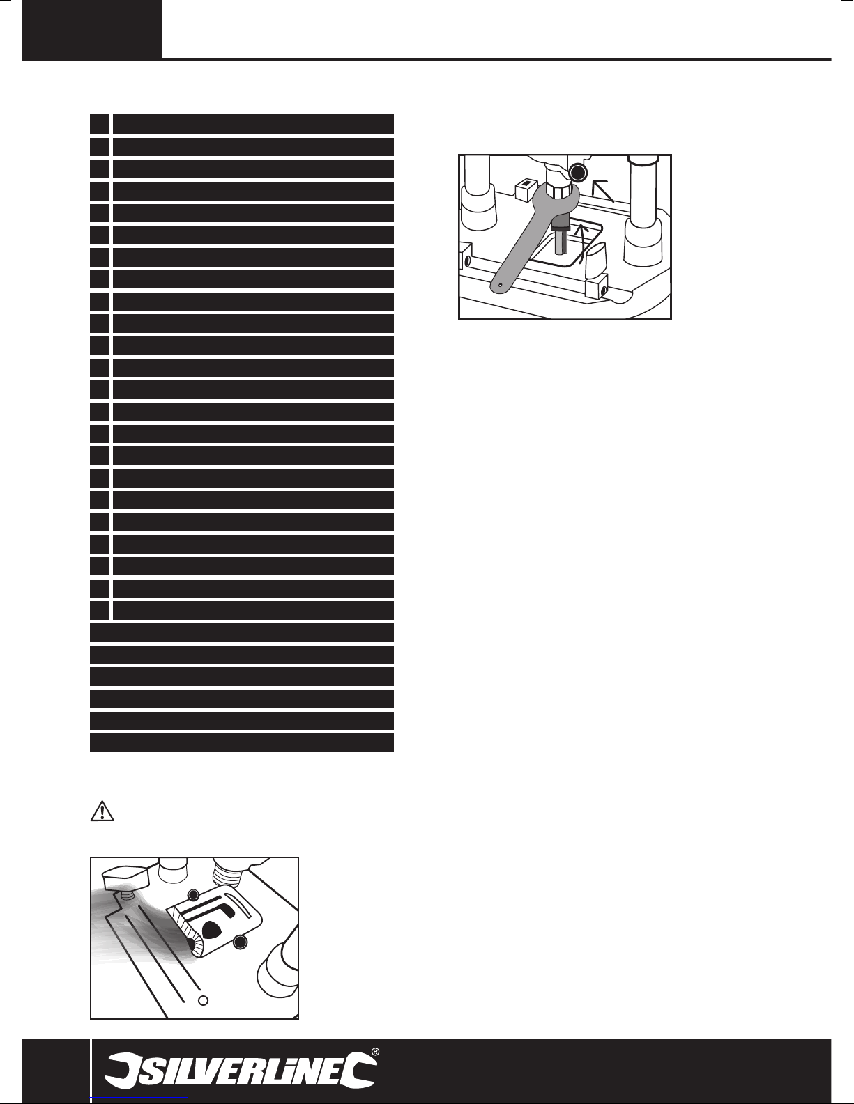
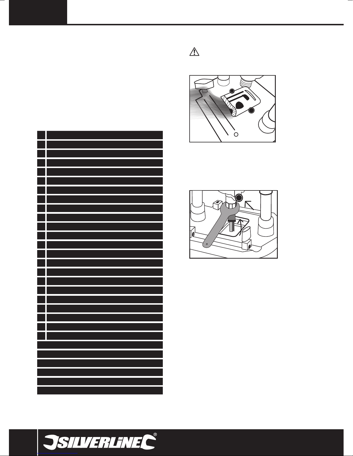
Installing a router bit
Note: Wear protective gloves when inserting and removing router bits due to the sharp
edges of the cutters.
• Press in the Spindle Lock Button (7) and rotate the spindle so that the lock engages
• The Collet Nut (8) can then be slackened (it may be necessary to use the supplied
spanner)
• Ensure that the correct size of collet is installed. If it is necessary to change the collet,
unscrew the Collet Nut completely, change the collet and replace the nut
• Insert the router bit into the collet, ensuring that at least 20mm, or half of the shaft
(whichever is greater) is inserted into the collet
• The Collet Nut can then be tightened using the Spanner supplied.
WARNING: DO NOT over tighten the collet nut, as this could cause damage to the collet
or the spindle lock.
Removing a router bit
• Press in the Spindle Lock Button (7) and loosen the Collet Nut (8).
The router bit should now be loose and can be removed
• If the router bit does not release from the collet, gently tap the collet nut to release.
WARNING: ALWAYS keep the collet, collet nut, spindle threads and router bit shank clean to
ensure a reliable and secure fitting.
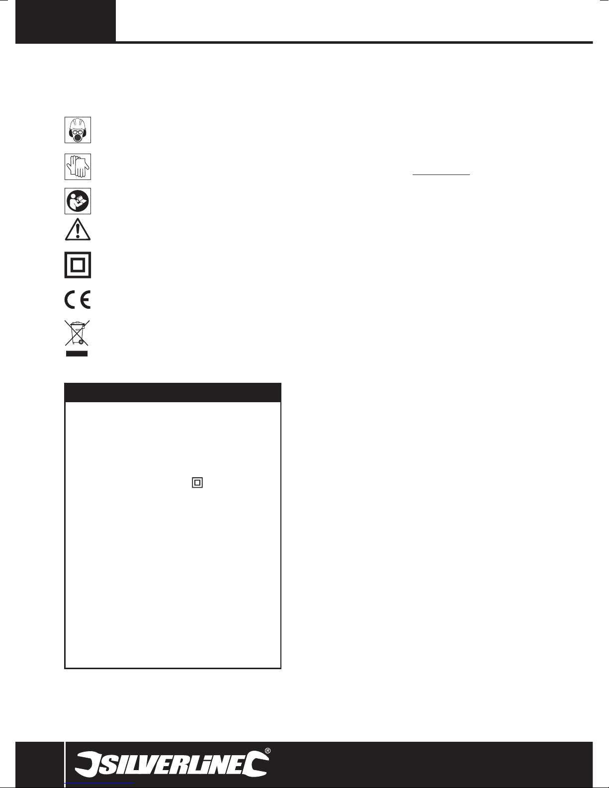
Fitting the parallel guide
• When grooving, or chamfering, use of the Parallel Guide (1) will help to ensure that
accurate cuts are made
1. Position the two Guide Rods (10) into the grooves in the top of the Base Plate (15)
2. Locate the Parallel Guide (1) onto the guide rods, so that it extends to the correct side of
the router for the cut that you intend to make
3. Slide the Parallel Guide to the required position relative to the cutter. The Measurement
Bar (19) can be clipped to the Guide Rod to help ensure accurate alignment. Ensure that
the plastic pads on the Parallel Guide are not in contact with the cutter
4. When making the cut, keep the vertical edge of the Parallel Guide held against the edge
of the workpiece
Fitting the circle guide
• The Circle Guide (23) allows accurate circles and arcs to be cut
1. Position a Guide Rod (10) into the rear groove in the top of the Base Plate (15)
2. Move a Guide Rod Locking Knob (6) to the rear groove so the Guide Rod is secured by
two Guide Rod Locking Knobs
3. Fit the Circle Guide onto the end of the Guide Rod, so that it extends to the correct side
of the router for the cut that you intend to make with the point facing downwards
4. Position the screw, washer and wing nut on the Circle Guide screw as required
depending on how you will anchor the Circle Guide. The wing nut may be used to create
the required height to the workpiece or secure the Circle Guide to the workpiece when
placed underneath the workpiece at the end of the thread
5. Ensure the Circle Guide assembly is held securely on the Guide Rod by tightening the
screw head or wing nut so the Circle Guide assembly is compressed and tight on the
Guide Rod
6. Adjust the Guide Rod position in the guide rod mountings to the required length (radius)
from anchor position to centre of router bit cutter
Using the roller guide
• The Roller Guide (22) attaches to the Parallel Guide (1). It enables the router to follow
the shape of the wood
1. Remove the two plastic pads from the Parallel Guide by removing the four screws
2. Attach the Roller Guide using two of the screws to the two inner threads of the parallel
fence. The Roller Guide wheel (trimmer guide) should face outward. So the Roller Wheel
faces the cutter
3. Attach the Parallel Guide with fitted Roller Guide to the router using two Guide Rods and
securing using Guide Rod Locking Knobs (6)
4. Adjust the Roller Guide height using the wing nut
6

www.silverlinetools.com
2050W Router124799
5. Adjust the distance between the router bit cutter and roller wheel by loosening the
Guide Rod Locking Knob on each side and positioning the Roller Guide to the correct
distance then retightening the Guide Rod Locking Knobs
6. To use, hold the router securely with both hands and make the cut by allowing the Roller
Guide to follow the contours of the wood. This can be used for curved workpieces
Note: Ensure the Roller Guide wheel is kept clean and rotates freely. Lubricate with a
suitable PTFE spray if necessary.
Using the guide bush plate
• The Guide Bush Plate (21) should be used when template/jig cutting. 30mm and 21mm
Guide Bush Plates are provided. 30mm is commonly used for kitchen jigs
1. Remove the Dust Extraction Port (14) by first removing the two bolts and nuts that
secure it
2. Remove the protective plastic pad from underneath the Base Plate (15) by removing the
four screws that secure it
3. On the internal side of the plastic pad fit the correct size Guide Bush Plate into the
recess with the bush (circular flange) facing outwards below the router
4. Refit the plastic pad with the four screws
5. Refit the Dust Extraction Port and dust extraction tubing
6. Fit the router bit at the correct height position suitable for the template or jig to be used
7. Make the cut as required carefully following the template or jig pattern
Operation
Adjusting the plunge depth
1. To release the plunge mechanism, rotate the Plunge Lock Lever (13) to its upper
position
2. The Depth Stop (3) can be adjusted by slackening the Depth Stop Lock (11), and rotating
the Depth Stop Adjuster (2) to the required position of the Depth Stop so the router bit
cutter is at the correct height when the router is plunged
3. Fine adjustment of the Depth Stop can be made using the Fine Adjustment Knob (12).
One full rotation will result in an approximate 1mm adjustment in Depth Stop height
4. Retighten the Depth Stop Lock at the correct Depth Stop height for the required cut so
when plunged the correct depth of the router bit cutter is exposed to the material
• The scale on the Depth Stop can be used to judge changes in depth setting, but actual
cutting depth is best measured by making a trial cut on scrap material
Setting the depth of cut
• To lock the router at a particular depth of cut, plunge the router head down and rotate
the Plunge Lock Lever (13) to its lower position. This will hold the router head in this
position
Making multiple pass cuts
1. The Turret Stop (9) allows the maximum depth of cut to be achieved in up to 7 steps.
Each step of the turret is equal to approximately 3mm depth of cut. Set the desired total
depth of cut using the depth stop, to the lowest turret step
2. Rotate the Turret Stop so that the Depth Stop will contact the highest step when the
router is plunged. The first pass of the cut can now be made
3. Continue to make passes, rotating the turret stop anti-clockwise by one step for each
pass until the full depth of cut has been achieved
Note: For total cuts of less than 21mm the number of steps will be reduced.
Base Plate
• The router features a combined flat-sided and round Base Plate (15). This allows the
round edge to follow contours easily but also gives an easy straight edge which may be
useful for some straight cuts (when the Parallel Guide (1) cannot be used), using with
guide bushes and also where the edge of the Base Plate needs to be closer to the router
bit cutter, e.g. for use with dovetail jigs etc.
• Always remember which edge of the base plate you are working with as the distance is
different to the router bit cutter
• If the router bit cutter impacts hard material such as metal the router bit will be
destroyed and the router itself may be damaged
Switching on and off
1. Ensure that the router bit is held securely in the collet, and that the router bit cutter is
not in contact with the workpiece or any other object
2. To start the motor, hold the Safety Button (16) down, and squeeze the On/Off Switch
(17). The motor will start. The router is equipped with a soft start feature so the motor
will take a few moments to reach its full operating speed
• To stop the motor, release the On/Off Switch
Speed control
• The speed of the router is set using the Variable Speed Dial (5): a higher number on the
dial corresponds to a higher motor speed
• Choosing the correct speed for the router bit and material will produce a higher quality
of finish, and prolong the service life of your router bits
Making a cut
Note: NEVER operate the router freehand without some form of guide. Guidance can be
provided by a bearing guided router bit cutter, the supplied guides, or a straight edge.
1. ALWAYS hold the router using both hands, on the handles provided. Ensure that the
workpiece will not move. Use clamps wherever possible
2. Allow the motor to reach its full operating speed
3. Lower the router bit cutter into the workpiece whilst moving the router slowly, keeping
the Base Plate (15) held flat against the workpiece
4. If edge cutting, the cutting of the workpiece should be on the left side relative to the
cutting direction. Keep the pressure constant and allow the cutter to work steadily
through the material. Be aware that knots, and other variations, will slow the rate of
progress
Note: To avoid 'bit chatter', direct the cut anticlockwise for external cuts, and clockwise
for internal cuts.
Note: Moving the router too fast can result in a poor quality finish, and overloading of the
motor. Moving the router too slowly can result in overheating the workpiece.
Note: Normal operation of a router is to plunge the head after the router has been
switched on
Accessories
A wide range of suitable accessories for this tool are available from your Silverline stockist,
including a large selection of cutter/router bits. Spares including carbon brushes, guide
bushes and collets are available from your Silverline stockist or www.toolsparesonline.com.
Maintenance
WARNING: ALWAYS disconnect from the power supply before cleaning or carrying
out maintenance.
General inspection
• Regularly check that all the fixing screws are tight. They may vibrate loose over time
• Inspect the supply cord of the tool, prior to each use, for damage or wear. Repairs
should be carried out by an authorised Silverline service centre. This advice also applies
to extension cords used with this tool
Cleaning
WARNING: ALWAYS wear protective equipment including eye protection and gloves when
cleaning this tool.
• Keep your tool clean at all times. Dirt and dust will cause internal parts to wear quickly,
and shorten the device’s service life
• Clean the body of your machine with a soft brush, or dry cloth
• Never use caustic agents to clean plastic parts. If dry cleaning is not sufficient, a mild
detergent on a damp cloth is recommended
• Water must never come into contact with the tool
• Ensure the tool is thoroughly dry before using it
• If available, use clean, dry, compressed air to blow through the ventilation holes (where
applicable)
Brushes
• Over time the carbon brushes inside the motor may become worn
• Excessively worn brushes may cause loss of power, intermittent failure, or visible
sparking
• To replace the brushes, remove the two Brush Access Covers (4) & (18). Remove the
worn brushes and ensure the sockets are clean. Carefully replace with new brushes and
then replace the Brush Access Covers
• After fitting run the router without load for 2-3 minutes to help the brushes bed in. The
process of the brushes fully bedding in may take repeated uses. Motor sparking may
continue until new carbon brushes have bedded in
• Alternatively, have the machine serviced at an authorised service centre
Disposal
Always adhere to national regulations when disposing of power tools that
are no longer functional and are not viable for repair.
• Do not dispose of power tools, or other waste electrical and electronic equipment
(WEEE), with household waste
• Contact your local waste disposal authority for information on the correct way to
dispose of power tools
7

GB
Troubleshooting
The following chart contains information designed to assist in diagnosing and resolving
router problems.
Problem Possible cause Solution
No supply of power Check that power is available at source
Router will not operate
Router runs or cuts slowly
Makes an unusual sound
Excessive vibration Incorrectly fitted or loose router bit Refit or tighten router bit
Heavy sparking occurs inside motor
Fine Adjustment Knob (12) “clicks” or
housing
not adjusting
Brushes worn or sticking
Switch is faulty Have the tool serviced by an authorised Silverline service centre
Motor components faulty or short circuited Have the tool serviced by an authorised Silverline service centre
Blunt or damaged cutter Resharpen or replace cutter
Variable Speed Dial (5) set low Increase variable speed setting
Motor is overloaded Reduce pushing force on router
Mechanical obstruction Have the tool serviced by an authorised Silverline service centre
Armature has shorted sections Have the tool serviced by an authorised Silverline service centre
Bent or damaged router bit Replace router bit
Brushes not moving freely Disconnect power, remove brushes, clean or replace
Armature short circuited or open circuited Have the tool serviced by an authorised Silverline service centre
Commutator dirty Have the tool serviced by an authorised Silverline service centre
Plunge Lock Lever (13) engaged Release Plunge Lock Lever
Disconnect power, open Brush Access Covers (4) & (18) and ensure brushes are not
damaged or heavily worn
Reached end of adjustment range Reset Fine Adjustment Knob and set depth with Depth Stop Adjuster (2)
8

www.silverlinetools.com
2050W Router124799
Silverline Tools Guarantee
This Silverline product comes with a 3 year guarantee
Register this product at www.silverlinetools.com within 30 days of purchase in order to
qualify for the 3 year guarantee. Guarantee period begins according to the date of purchase
on your sales receipt.
Registering your purchase
Terms & Conditions
Guarantee period becomes effective from the date of retail purchase as detailed on your
sales receipt.
PLEASE KEEP YOUR SALES RECEIPT
If this product develops a fault within 30 days of purchase, return it to the stockist where it
was purchased, with your receipt, stating details of the fault. You will receive a replacement
or refund.
If this product develops a fault after the 30 day period, return it to:
Silverline Tools Service Centre
PO Box 2988
Yeovil
BA21 1WU, UK
The guarantee claim must be submitted during the guarantee period.
You must provide the original sales receipt indicating the purchase date, your name, address
and place of purchase before any work can be
carried out.
You must provide precise details of the fault requiring correction.
Claims made within the guarantee period will be verified by Silverline Tools to establish if the
deficiencies are related to material or manufacturing of the product.
Carriage will not be refunded. Items for return must be in a suitably clean and safe state for
repair, and should be packaged carefully to prevent damage or injury during transportation.
We may reject unsuitable or
unsafe deliveries.
All work will be carried out by Silverline Tools or its authorized
repair agents.
The repair or replacement of the product will not extend the period
of guarantee
Defects recognised by us as being covered by the guarantee shall be corrected by means of
repair of the tool, free of charge (excluding carriage charges) or by replacement with a tool
in perfect working order.
Retained tools, or parts, for which a replacement has been issued, will become the property
of Silverline Tools.
The repair or replacement of your product under guarantee provides benefits which are
additional to and do not affect your statutory rights as a consumer.
What is covered:
The repair of the product, if it can be verified to the satisfaction of Silverline Tools that the
deficiencies were due to faulty materials or workmanship within the guarantee period.
Registration is made at silverlinetools.com by selecting the Guarantee Registration button.
You will need to enter:-
• Your personal details
• Details of the product and purchase information
Once this information is entered your guarantee certificate will be created in PDF format for
you to print out and keep with your purchase.
If any part is no longer available or out of manufacture, Silverline Tools will replace it with a
functional replacement part.
Use of this product in the EU.
What is not covered:
Silverline Tools does not guarantee repairs required as a result of:
Normal wear and tear caused by use in accordance with the operating instructions eg
blades, brushes, belts, bulbs, batteries etc.
The replacement of any provided accessories drill bits, blades, sanding sheets, cutting discs
and other related items.
Accidental damage, faults caused by negligent use or care, misuse, neglect, careless
operation or handling of the product.
Use of the product for anything other than normal domestic purposes.
Change or modification of the product in any way.
Use of parts and accessories which are not genuine Silverline Tools components.
Faulty installation (except installed by Silverline Tools).
Repairs or alterations carried out by parties other than Silverline Tools or its authorized
repair agents.
Claims other than the right to correction of faults on the tool named in these guarantee
conditions are not covered by the guarantee.
CE Declaration of Conformity
The undersigned: Mr Darrell Morris
as authorised by: Silverline Tools
Declares that
Identification code: 124799
Description: 2050W 1/2” Plunge Router
Conforms to the following directives and standards:
• Machinery Directive 2006/42/EC
• EMC Directive 2004/108/EC
• RoHS Directive 2011/65/EU
• EN 60745-2-17:2010
• EN 60745-1:2009+A11:2010
• EN 55014-1:2006+A1:2009
• EN 55014-2:1997+A1:2001+A2:2008
• EN 61000-3-2:2006+A1:2009+A2:2009
• EN 61000-3-3:2008
Notified body: Intertek Testing Services, Shanghai, China
The technical documentation is kept by: Silverline Tools
Date: 07/04/14
Signed:
Mr Darrell Morris
Managing Director
Name and address of the manufacturer:
Powerbox International Limited, Company No. 06897059. Registered address: Central House,
Church Street, Yeovil, Somerset BA20 1HH,
United Kingdom.
9
F
F
Description des symboles
La plaque signalétique figurant sur votre outil peut présenter des symboles.
Ces symboles constituent des informations importantes relatives au produit ou des
instructions concernant son utilisation.
Port de protection auditive
Port de lunettes de sécurité
Port du masque respiratoire
Port du casque
Port de gants
Lire le manuel d’instructions
Caution!
Double isolation pour une protection supplémentaire
Conforme à la règlementation et aux normes européennes de sécurité
pertinentes
Protection de l’environnement
Les produits électriques usagés ne doivent pas être jetés avec les ordures
ménagères. Veuillez les recycler dans les centres prévus à cet effet. Pour
de plus amples informations, veuillez contacter votre municipalité ou
point de vente.
Caractéristiques techniques
Tension : .......................................230 à 240 V~ 50 Hz
Puissance : ...................................2050 W
Vitesse à vide : .............................6000-24,000 min
Profondeur de plongée : ...............50 mm
Pinces de serrage :.......................¼", ½", 8 et 12 mm
Forme de la plaque de base : .......Combinée : circulaire et plate
Classe de protection : ...................
Indice de protection: .....................IP20
Longueur du câble d’alimentation :2,5 m
Dimensions (H x L x l): ..................315 x 320 x 158 mm
Poids: ...........................................5,65 kg
Informations concernant le bruit et les vibrations:
Pression sonore (LPA): ...................92,4 dB(A)
Puissance acoustique (LWA): ..........103,4 dB(A)
Incertitude: ...................................3 dB(A)
Vibration pondérée: ......................4,77 m/s
Incertitude: ...................................1,5 m/s
Le niveau d’intensité sonore subi par l’opérateur peut dépasser 85 dB(A) et il est
par conséquent nécessaire de prendre des mesures de protection sonore.
Du fait de l’évolution constante de notre développement produits, les
caractéristiques techniques des produits Silverline peuvent changer sans
Attention : Toujours porter des protections sonores lorsque le niveau d’intensité est
supérieur à 85 dB(A) et limiter le temps d’exposition si nécessaire. Si l’intensité sonore
devient inconfortable, même avec les protections, arrêter immédiatement d’utiliser
l’appareil, vérifier que les protections soient bien mises et qu’elles soient adéquates avec
le niveau sonore produit par l’appareil.
notification préalable.
-1
2
2
Attention : L’exposition de l’utilisateur aux vibrations peut engendrer une perte du toucher,
des engourdissements, des picotements et ainsi réduire la capacité de préhension. De
longues expositions peuvent également provoquer ces symptômes de façon chronique.
Si nécessaire, limiter le temps d’exposition aux vibrations, et porter des gants antivibrations. Ne pas utilisez cet appareil avec vos mains sous des conditions en dessous
de températures normales, car l’effet vibratoire en est accentué. Se référer au cas de
figures des caractéristiques relatives aux vibrations pour calculer le temps et fréquence
d’utilisation de l’appareil.
Les niveaux sonores et vibratoires des caractéristiques techniques sont déterminés
en fonction de la norme EN60745 ou autres normes internationales. Ces données
correspondent à un usage normale de l’appareil, et ce dans des conditions de travail
normales. Un appareil mal entretenu, mal assemblé ou mal utilisé peut augmenter les
niveaux sonores et vibratoires. Pour plus d’informations sur la directive des émissions
sonores et vibratoires, visitez le site http://osha.europa.eu/fr.
Consignes générales de sécurité
AVERTISSEMENT : Veuillez lire l’intégralité des consignes de sécurité et des
instructions. Le non-respect de ces consignes et instructions peut entraîner un risque de
choc électrique, d’incendie et/ou se traduire par des blessures graves.
Attention : Cet appareil n’est pas conçu pour être utilisé par des personnes (enfants
compris) ayant des capacités physiques ou mentales réduites, ou n’ayant pas la
connaissance ou l’expérience requise, à moins d’être sous la supervision d’une
personne responsable de leur sécurité ou d’avoir reçu les instructions nécessaires.
Les enfants ne doivent pas s’approcher et jouer avec cet appareil.
Veuillez conserver ces instructions et consignes de sécurité
pour référence ultérieure.
L’expression « appareil électrique » employée dans les présentes consignes recouvre aussi
bien les appareils filaires à brancher sur le secteur que les appareils sans fils fonctionnant
sous batterie.
Sécurité sur la zone de travail
a) Maintenir une zone de travail propre et bien éclairée. Des zones encombrées et
mal éclairées sont sources d’accidents.
b) Ne pas utiliser d’outils électriques dans des environnements explosifs, tels
qu’à proximité de liquides, de gaz ou de poussières inflammables. Les appareils
électriques produisent des étincelles susceptibles d’enflammer la poussière ou les
vapeurs présentes.
c) Eloigner les enfants et les passants pendant l’utilisation d’un appareil
électrique. Ceux-ci peuvent provoquer une perte d’attention et faire perdre la
maîtrise de l’appareil.
Sécurité électrique
a) La prise d’un appareil électrique doit être adaptée à la prise du secteur. Ne
jamais modifier la prise en aucune façon. Ne jamais utiliser d’adaptateur sur la
prise électrique d’appareil mis à la terre. Des prises non modifiées, adaptées aux
boîtiers de prise de courant, réduiront le risque de décharge électrique.
b) Eviter le contact corporel avec les surfaces mises à la terre telles que tuyaux,
radiateurs, cuisinières et réfrigérateurs. Le risque de décharge électrique est plus
important si le corps est mis à la terre.
c) Ne pas exposer l’appareil électrique à la pluie ou à l’humidité. L’infiltration d’eau
dans un appareil électrique accroît le risque de décharge électrique.
d) Ne pas maltraiter le cordon électrique. Ne jamais utiliser le cordon électrique
pour porter, tirer ou débrancher l’appareil. Protéger le cordon électrique de la
chaleur, du contact avec l’essence, des bords tranchants et pièces rotatives.
Un cordon électrique endommagé ou entortillé accroît le risque de décharge
électrique.
e) Lors d’une utilisation de l’appareil électrique en extérieur, se servir d’une
rallonge appropriée à une utilisation en extérieur. Cela réduit le risque de
décharge électrique.
f) Si une utilisation de l’appareil électrique dans un environnement humide
ne peut être évitée, utiliser une alimentation protégée par un disjoncteur
différentiel. L’utilisation d’un disjoncteur différentiel réduit le risque de décharge
électrique.
ATTENTION : Lorsque utilisé en Australie ou en Nouvelle Zélande, il est recommandé que
cet appareil soit toujours alimenté via un disjoncteur différentiel ayant un courant résiduel
de 30 mA ou moins.
Sécurité des personnes
a) Rester vigilant et faire preuve de bon sens lors de la manipulation de l’appareil. Ne
pas utiliser un appareil électrique lorsque l’on se trouve dans un état de fatigue, ou
sous l’influence de drogues, d’alcool ou de médicaments. Un moment d’inattention
pendant l’utilisation d’un outil électrique peut se traduire par des blessures graves.
b) Porter un équipement de protection approprié. Toujours porter une protection
oculaire. Le port de masque à poussières, chaussures de sécurité antidérapantes,
casque de sécurité et protections antibruit adaptés aux différentes conditions de
travail réduit le risque de blessures corporelles.
c) Eviter tout démarrage accidentel ou intempestif. S’assurer que l’interrupteur
marche-arrêt soit en position d’arrêt avant de brancher l’appareil sur
l’alimentation secteur ou d’installer la batterie, de prendre l’appareil ou de
10
10

www.silverlinetools.com
Défonceuse 2050 W124799
le transporter. Porter un appareil électrique tout en maintenant le doigt posé sur
l’interrupteur ou brancher un appareil électrique dont l’interrupteur est sur la position
de marche est source d’accidents.
d) Enlever toute clé et tout instrument de réglage avant de mettre l’appareil
électrique en marche. Une clé ou un instrument de réglage laissé fixé à un élément
en rotation de l’appareil électrique peut entraîner des blessures physiques.
e) Ne pas essayer d’atteindre une zone hors de portée. Se tenir toujours en
position stable permettant de conserver l’équilibre. Cela permet de mieux
contrôler l’appareil électrique dans des situations inattendues.
f) Porter des vêtements appropriés. Ne pas porter de vêtements amples ou
des bijoux pendants. Eloigner cheveux, vêtements et gants des pièces en
mouvement. Les vêtements amples, les bijoux pendants et cheveux longs peuvent
être happés par les pièces en rotation.
g) Si l’appareil est pourvu de dispositifs destinés au raccord d’équipements
d’extraction et de récupération de la poussière/sciure, s’assurer qu’ils soient
bien fixés et utilisés correctement. L’utilisation de ces dispositifs peut réduire les
risques dus à la poussière.
Utilisation et entretien des appareils électriques
a) Ne pas forcer sur l’appareil électrique. Utiliser l’appareil électrique approprié
au travail à effectuer. Un appareil électrique adapté et employé au rythme pour
lequel il a été conçu permettra de réaliser un travail de meilleure qualité et dans de
meilleures conditions de sécurité.
b) Ne pas utiliser un appareil électrique dont l’interrupteur marche-arrêt est
hors service. Tout appareil électrique dont la commande ne s’effectue plus par
l’interrupteur marche-arrêt est dangereux et doit être réparé.
c) Débrancher l’appareil électrique ou démonter sa batterie avant d’effectuer tout
réglage ou changement d’accessoire et avant de le ranger. De telles mesures
préventives réduiront les risques de démarrage accidentel.
d) Ranger les appareils électriques inutilisés hors de portée des enfants et ne
pas permettre l’utilisation de cet appareil aux personnes non habituées à
son maniement ou n’ayant pas lu les présentes instructions. Les appareils
électriques sont dangereux dans les mains d’utilisateurs inexpérimentés.
e) Veiller à l’entretien des appareils électriques. Vérifier que les éléments
rotatifs soient bien alignés et non grippés. S’assurer de l’absence de pièces
cassées ou endommagées susceptibles de nuire au bon fonctionnement de
l'appareil. Si l’appareil électrique est endommagé, le faire réparer avant toute
utilisation. De nombreux accidents sont dus à l’utilisation d’appareils électriques
mal entretenus.
f) Veiller à ce que les outils de coupe soient tenus affûtés et propres. Des outils de
coupe bien entretenus, aux tranchants bien affûtés, sont moins susceptibles de se
gripper et sont plus faciles à contrôler.
g) Utiliser l’appareil électrique, les accessoires et outils à monter conformément
à ces instructions, en tenant compte des conditions de travail et de la tâche à
réaliser. Toute utilisation d’un appareil électrique autre que celle pour laquelle il a
été conçu peut entraîner des situations à risque.
ATTENTION : Lorsque utilisé en Australie ou en Nouvelle Zélande, il est recommandé que
cet appareil soit toujours alimenté via un disjoncteur différentiel ayant un courant résiduel
de 30 mA ou moins.
Révision
a) Ne faire réparer votre appareil électrique que par un réparateur qualifié
utilisant uniquement des pièces de rechange identiques. Cela permet de
maintenir la sécurité d’utilisation de l’appareil électrique.
Consignes de sécurité
supplémentaires concernant les
défonceuses électriques
• Tenez l’outil électrique par les surfaces de préhension isolées uniquement afin d’éviter
un choc électrique si l’outil coupe son propre câble d’alimentation ou un autre câble
électrique.
• Utilisez un serre-joint ou un étau pour maintenir la pièce de travail sur une surface
stable. Si vous tenez la pièce de travail dans votre main ou contre votre corps, vous
risquez de perdre le contrôle de l’appareil.
• Utilisez des équipements de sécurité tels que des lunettes de sécurité, des protections
antibruit, un masque à poussière et des vêtements protecteurs dont des gants de
sécurité.
• Il ne faut jamais laisser des chiffons, des tissus, des cordons, de la ficelle et des objets
similaires à proximité de la zone de travail.
• Assurez-vous que la tension de l’alimentation secteur soit la même que celle indiquée
sur l’outil.
• Lorsqu’il est nécessaire d’utiliser une rallonge, il est nécessaire de s’assurer que son
ampérage nominal correspond à celui de l’outil électrique et qu’elle est en bon état.
• Déroulez complètement le rouleau de câble de rallonge électrique afin d’éviter le risque
de surchauffe.
• Utilisez des détecteurs appropriés pour déterminer si des câbles ou canalisations sont
présents sous la surface de travail. Appelez les entreprises de services publics pour
de l’aide si nécessaire. Entrer en contact avec les câbles électriques peut exposer
l’utilisateur à des chocs électriques et à un incendie. Endommager une canalisation de
gaz peut causer une explosion. Entrer en contact avec les conduites d’eau peut causer
des dommages matériels importants.
• Assurez-vous d’avoir enlevé les corps étrangers tels que les clous et les vis de la pièce
de travail avant de commencer à travailler.
• Manipulez les fraises avec précaution ; elles peuvent être extrêmement coupantes.
• Vérifiez si la fraise est endommagée ou fendue avant de l’utiliser. Si c’est le cas,
remplacez-la immédiatement.
• Assurez-vous que les fraises sont affutées et bien entretenues. Des tranchants non
affutés peuvent causer des pertes de contrôle telles que le calage, une augmentation de
la chaleur et un risque de blessures.
• Utilisez toujours les deux poignées et tenez la défonceuse fermement avant de
commencer à travailler.
• Gardez les poignées et les surfaces de préhension sèches, propres et exemptes d’huile
ou de graisse afin de vous assurer que l’outil peut être tenu de manière sure.
• Avant d’utiliser cet outil pour réaliser un fraisage, mettez-le en marche et laissez-le
fonctionner pendant un instant. Regardez si l’outil vibre ou oscille d’une manière qui
pourrait indiquer une mauvaise installation de la fraise.
• Remarquez le sens de rotation de la fraise et celui du déplacement de l’outil.
• Gardez vos mains loin de la fraise et de la zone de défonçage. Tenez la poignée
auxiliaire ou une surface de préhension isolée avec votre deuxième main.
• Ne mettez jamais la défonceuse en marche lorsque la fraise est en contact avec la
pièce de travail.
• Assurez-vous que le ressort de plongée est toujours installé pendant l’utilisation de la
défonceuse à main.
• Assurez-vous que la fraise est complètement arrêtée avant de plonger l'appareil pour le
mettre en position de blocage du collet.
• La vitesse maximale de la fraise doit être égale ou supérieure à la vitesse maximale
de l’outil.
• Certaines parties de la fraise peuvent devenir chaudes lors de l’utilisation. Ne manipulez
pas immédiatement après utilisation afin d’éviter tout risque de brûlure.
• Ne laissez pas les pièces de la défonceuse entrer en contact avec des matériaux
combustibles.
• La taille de la tige de la fraise doit être exactement adaptée à la pince de serrage de
votre défonceuse. Des fraises montées incorrectement auront une rotation irrégulière et
une augmentation des vibrations qui pourrait causer une perte de contrôle.
• N’appuyez pas sur le bouton de verrouillage de l’arbre, et n’essayez pas de mettre la
défonceuse en mode changement de fraise lorsque la défonceuse est en marche.
• Exercez une pression constante lorsque vous coupez la pièce de travail, et laissez la
fraise dicter la vitesse de coupe. Ne forcez pas l’outil et ne surchargez pas le moteur.
• Assurez-vous que la plaque signalétique et les avertissements de sécurité sur l’outil
sont lisibles et remplacez-les s’ils deviennent marqués ou endommagés.
• Lorsque vous vous servez de la défonceuse, soyez prêts pour un calage de la fraise
dans la pièce de travail qui pourrait vous faire perdre contrôle. Assurez-vous que vous
tenez la défonceuse fermement et que vous relâchez l’interrupteur marche-arrêt
immédiatement dans de telles circonstances.
• Après avoir mis en marche la défonceuse, vérifiez que la fraise tourne de manière
uniforme (sans « tremblements ») et qu’il n’y a pas de vibrations supplémentaires
causées par un montage incorrect de la fraise. L’utilisation de cette défonceuse avec
une fraise montée incorrectement peut causer une perte de contrôle et des blessures
graves.
• Il faut faire très attention de ne pas surcharger le moteur pendant l’utilisation de fraises
d’un diamètre supérieur à 50 mm (2"). Déplacez très lentement l’appareil et/ou faites de
multiples fraisages peu profonds pour éviter la surcharge du moteur.
• Arrêtez toujours l’appareil et attendez que la fraise soit complètement arrêtée avant de
retirer la défonceuse de la pièce de travail.
• Débranchez toujours l’appareil de l’alimentation secteur avant de le régler, de le réparer
ou de l’entretenir.
ATTENTION : La poussière créée par l’utilisation d’outils électriques peut être toxique.
Certains matériaux ont subi un traitement ou un revêtement chimique et peuvent constituer
un risque toxique. Certains matériaux naturels et composites peuvent contenir des produits
toxiques. Certaines vieilles peintures peuvent contenir du plomb ou d’autres produits
chimiques. Evitez une exposition prolongée à la poussière créée par la défonceuse. Ne
laissez pas la poussière entrer en contact avec la peau ou les yeux et ne laissez pas la
poussière pénétrer dans votre bouche afin d’éviter l’absorption de produits nocifs. Si
possible, travaillez dans un lieu bien aéré. Utilisez un masque anti-poussière adapté et
un système d’extraction des poussières si possible. Plus vous êtes exposé à la poussière
souvent et plus il est important de suivre les précautions de sécurité et d’utiliser un niveau
de protection individuelle plus élevé.
www.silverlinetools.com
11
11
F
Usage conforme
Défonceuse manuelle pour utilisation avec fraises dont la tige a un diamètre de ¼”,
½”, 8 mm, 10 mm et 12 mm (en fonction de la pince de serrage montée). Utilisée pour
couper des profilés, des rainures, des bords et des trous allongés dans les bois naturels
et composites. Egalement utilisée avec bagues de guidage et gabarits pour découper des
formes, suivre des schémas, ainsi que pour montage stationnaire sur système de table
pour défonceuse adapté.
Déballage
• Déballez l’outil avec soin et vérifiez-le. Familiarisez-vous avec toutes ses
caractéristiques et fonctions.
• Assurez-vous qu’il ne manque aucune pièce et que l’appareil est en bon état. Si des
pièces sont endommagées ou manquantes, faites-les réparer ou remplacer avant
d’utiliser l’appareil.
Se familiariser avec le produit
1 Guide parallèle
2 Molette de réglage de la profondeur
3 Butée de profondeur
4 Cache d’accès aux charbons
5 Sélecteur de vitesse
6 Bouton de verrouillage de la tige de guidage
7 Bouton de blocage de l’arbre
8 Ecrou de la pince de serrage
9 Butée revolver
10 Tige de guidage
11 Verrouillage de butée de profondeur
12 Bouton de réglage précis
13 Levier de verrouillage de plongée
14 Orifice d’extraction de la poussière
15 Plaque de base
16 Interrupteur de sécurité
17 Interrupteur marche-arrêt
18 Cache d’accès aux charbons
19 Barre de mesure
20 Pince de serrage
21 Bague de guidage
22 Rouleau de guidage
23 Guide circulaire
Accessoires (non illustrés):
1 x clé pour pinces de serrage
5 x fraises
1 x clé hexagonale
2 x charbons de rechange
1 x bague de guidage supplémentaire
Avant utilisation
ATTENTION : Assurez-vous que la machine soit toujours débranchée de
l’alimentation électrique avant de monter ou d’enlever des accessoires ou de
changer les réglages de la machine.
Installation de l’orifice d’extraction de la poussière
• Fixez l’orifice d’extraction de la poussière (14) à la plaque de base (15) en utilisant les
écrous et les vis fournis.
• La poussière de certains matériaux peut être toxique. Fixez un système d’extraction
de la poussière à l’orifice d’extraction de la poussière (14) à chaque fois que possible,
avant d’utiliser cette défonceuse.
Installation d’une fraise
Remarque : Portez des gants de protection lorsque vous insérez et enlevez les fraises car
leurs tranchants sont très affutés
1. Appuyez sur le bouton de blocage de l’arbre (7) et faites tourner l’arbre jusqu’à ce qu’il
se verrouille.
2. L’écrou de pince de serrage (8) peut ensuite être desserré (il peut être nécessaire
d’utiliser la clé fournie).
3. Assurez-vous que la taille correcte de pince de serrage est installée. S’il est nécessaire
de changer la pince de serrage, dévissez l’écrou de pince de serrage complètement,
changez la pince de serrage et replacez l’écrou de pince de serrage.
4. Insérez la fraise dans la pince de serrage, en vous assurant qu’au moins 20 cm, ou la
moitié de la tige (en vous servant du nombre le plus élevé) soit inséré dans la pince de
serrage.
5. L’écrou de pince de serrage peut ensuite être serré en vous servant de la clé fournie.
ATTENTION : Ne serrez pas trop l’écrou de pince de serrage, car ceci pourrait
endommager la pince de serrage ou le blocage de l’arbre.
Enlever une fraise
1. Appuyez sur le bouton de blocage de l’arbre (7) et desserrez l’écrou de pince de serrage
(8). La fraise devrait à présent être prête à enlever.
2. Si la fraise ne sort pas de la pince de serrage, tapez doucement sur l’écrou de pince de
serrage pour l’enlever.
ATTENTION : Gardez toujours la pince de serrage, l’écrou de pince de serrage, le filetage
de l’arbre et les fraises propres afin d’assurer une fixation fiable et sure.
Installation du guide parallèle
• En rainurant ou en chanfreinant, l’utilisation du guide parallèle (1) aide à garantir la
précision de la découpe.
1. Positionnez les deux tiges de guidage (10) dans les deux rainures sur le dessus de la
plaque de base (15).
2. Posez le guide parallèle (1) sur les tiges de guidage de manière à ce qu’il atteigne le
côté de la défonceuse adapté à la découpe à effectuer.
3. Faites glisser le guide parallèle (1) dans la position requise et adaptée à la fraise. La
barre de mesure (19) peut être fixée sur la tige de guidage pour s’assurer d’un bon
12F12
 Loading...