

Page 1
Service
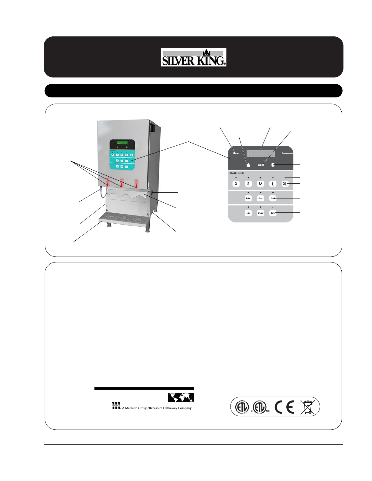
Product Identification
M I L K C R S K I MM
S E L E C T P
P O D U C TR
Door-Display
Connector
Cable
Display Panel
Drip Tray
Power Switch
(on side)
Product Valves
Cup Guide
USB Port
Power Cord
(under)
Home Button
Up Arrow
LCD Display
Select Button
Down Arrow
Back Button
LEDs
Size Buttons
Recipe Buttons
Product Buttons
TABLE OF CONTENTS
Product Identification . . . . . . . . . . . . . . . . . . . . . . . . . . . . . . . 1
Limited Warranty . . . . . . . . . . . . . . . . . . . . . . . . . . . . . . . . . . 2
Silver King Serial Number Matrix . . . . . . . . . . . . . . . . . . . . . 2
Safety Information . . . . . . . . . . . . . . . . . . . . . . . . . . . . . . . . . 3
General . . . . . . . . . . . . . . . . . . . . . . . . . . . . . . . . . . . . . . . . . 3
Important . . . . . . . . . . . . . . . . . . . . . . . . . . . . . . . . . . . . . . . . 3
Electrical Specifications . . . . . . . . . . . . . . . . . . . . . . . . . . . . 3
Safe Service Practices. . . . . . . . . . . . . . . . . . . . . . . . . . . . . . 4
Display Menu Overview . . . . . . . . . . . . . . . . . . . . . . . . . . . . . 4
Resetting Factory Defaults. . . . . . . . . . . . . . . . . . . . . . . . . . . 5
Setting Time and Date . . . . . . . . . . . . . . . . . . . . . . . . . . . . . . 6
Calibrating the Unit / Adjusting Shot Size . . . . . . . . . . . . . . . 7
Shot Size Targets . . . . . . . . . . . . . . . . . . . . . . . . . . . . . . . . . . 8
Updating and Exporting Files . . . . . . . . . . . . . . . . . . . . . . . . . 9
Changing Set Point, Base, Low Product Thresholds,
Beeper Status. . . . . . . . . . . . . . . . . . . . . . . . . . . . . . . . . . . . . 10
Zeroing Out the Load Cells . . . . . . . . . . . . . . . . . . . . . . . . . . 11
Viewing Other Load Cell Data . . . . . . . . . . . . . . . . . . . . . . . . 12
Solenoids – Test Cycling/Viewing Status . . . . . . . . . . . . . . . . 12
Compressor – Test Cycling/Setting Up . . . . . . . . . . . . . . . . . 13
Troubleshooting Guide. . . . . . . . . . . . . . . . . . . . . . . . . . . . . . 14
Accessing/Servicing Components from the Front . . . . . . . . . 15
Accessing/Servicing Components from the Rear. . . . . . . . . . 18
Parts List and Exploded View . . . . . . . . . . . . . . . . . . . . . . . . 20
Wiring Diagram . . . . . . . . . . . . . . . . . . . . . . . . . . . . . . . . . . . 21
355 East Kehoe Blvd. • Carol Stream, IL 60188 USA
Telephone: 630-462-8800 • Toll Free: 1-800-PCASTLE
Fax: 630-462-1460 • www.princecastle.com
Manual
3-Product
Dairy Dispenser
Model SKBD3LS
808-004-EN Printed in USA 10/13 © 2013
P
RINC
E
C
A
STL
E
LLC
WORLDWIDE
Page 2

3-Product Dairy Dispenser
Limited Warranty
This Silver King branded product is warranted to be free from
defects in material and/or workmanship for a period of two (2)
years from the date of original installation, not to exceed 30
months from date of shipment from our factory. Any part or
component which proves to be faulty in material and/or
workmanship (in the opinion of Prince Castle) within the warranty
period will be replaced or repaired (at the option of Prince Castle)
without cost to the customer for parts or labor, except as provided
below. The compressor will carry an additional three (3) years
parts only warranty.
This Limited Warranty is subject to the following exceptions/
conditions.
• Use of any non OEM parts voids warranty unless otherwise
approved by Prince Castle. All work must be performed by an
authorized Prince Castle Service Agent, except as provided
herein.
• All covered labor requires preauthorization from the factory
(Call 1-888-375-2938) and shall be performed during regular
work hours. Overtime premium will not be covered.
• Travel charges are to be limited to 100 miles (200 Kilometers)
round trip: 2 hours travel time per one trip repair.
• Adjustments of any kind are not covered under this Limited
Warranty.
• Damage caused by carelessness, neglect, and/or abuse (e.g.,
using incorrect voltage, dropping, tampering with or altering
electrical components, or improper cleaning) is not covered.
• Equipment damaged in shipment or by fire, flood or act of God
is not covered.
• Damage to coated surfaces is not covered by this Limited
Warranty.
• Use of refrigerants other than specified on the equipment
serial plate voids the warranty.
• Labor repair or replacement of the following parts is not
covered by this Limited Warranty:
– Main Control Board p/n 36992S; Prince Castle will provide
replacement parts to customer so customer can replace
such parts if they are defective. Replacement instructions
are included with part supplied.
– Door Gasket p/n 36956S, Product Containers and Lids (p/n
37068S, 37069S, 37070S and 811-006S), Drip Tray p/n
37281S and cup guides p/n 37436S are considered wear
items and are not included under the warranty.
PRINCE CASTLE SHALL NOT BE LIABLE FOR INCIDENTAL
OR CONSEQUENTIAL DAMAGES, LOSSES, OR EXPENSES.
PRINCE CASTLE MAKES NO OTHER WARRANTY, EXPRESS
OR IMPLIED. ALL IMPLIED WARRANTIES OF
MECHANTABILITY AND/OR FITNESS FOR ANY PARTICULAR
PURPOSE ARE HEREBY DISCLAIMED AND EXCLUDED.
Silver King Serial Number Matrix
The manufacture date (year and month) is encoded in the serial
number’s 2nd, 3rd and 4th letters. The service bench installation
date (used to determine warranty coverage) is considered to be
the end of the following month.
The refrigerant used in the unit appears as the serial number’s last
letter.
For example:
Serial Number: SAIE
53264A
Manufacture Date: April 2008
Service Bench Installation Date: May 31, 2008
Refrigerant Used: R-134a
Manufacture Date
Refrigerant Used
2000 2001 2002 2003 2004 2005 2006 2007 2008 2009 2010 2011 2012
AA AB AC AD AE AF AG AH AI AJ BA BB BC
January B AAB ABB ACB ADB AEB AFB AGB AHB AIB AJB BAB BBB BCB
February C AAC ABC ACC ADC AEC AFC AGC AHC AIC AJC BAC BBC BCC
March D AAD ABD ACD ADD AED AFD AGD AHD AID AJD BAD BBD BCD
April E AAE ABE ACE ADE AEE AFE AGE AHE AIE AJE BAE BBE BCE
May F AAF ABF ACF ADF AEF AFF AGF AHF AIF AJF BAF BBF BCF
June G AAG ABG ACG ADG AEG AFG AGG AHG AIG AJG BAG BBG BCG
July H AAH ABH ACH ADH AEH AFH AGH AHH AIH AJH BAH BBH BCH
August I AAI ABI ACI ADI AEI AFI AGI AHI AII AJI BAI BBI BCI
September J AAJ ABJ ACJ ADJ AEJ AFJ AGJ AHJ AIJ AJJ BAJ BBJ BCJ
October K AAK ABK ACK ADK AEK AFK AGK AHK AIK AJK BAK BBK BCK
November L AAL ABL ACL ADL AEL AFL AGL AHL AIL AJL BAL BBL BCL
December M AAM ABM ACM ADM AEM AFM AGM AHM AIM AJM BAM BBM BCM
ABMR
R-134a R-404a (MP-39) R401a R-22
Model SKBD3LS
P
RINC
E
C
A
STL
E
LLC
WORLDWIDE
Printed in USA 10/13 © 2013 2 808-004-EN
Page 3
3-Product Dairy Dispenser
P
RINC
E
C
A
STL
E
LLC
WORLDWIDE
Safety Information
Indicates information important to the proper operation of
the unit. Failure to observe may result in damage to the
equipment and/or severe bodily injury or death.
Indicates information important to the operation of the unit.
Failure to observe may result in damage to the equipment.
WARNING
CAUTION
General Precautions
Risk of Electric Shock.
• Always unplug the power cord before servicing the unit to
avoid electric shock.
• Unit MUST be plugged into a 3-prong plug for grounding.
Cutting off the grounding spike on the power cord could
result in electric shock to the operator during operation.
• Unit must be plugged into a 15 or 20 ampere fuse- or
breaker-protected circuit. Use of a larger fuse or breaker
could result in damage to the unit and electric shock to the
operator.
Moving or Handling Hot Parts.
• Some parts may remain hot even after being unplugged.
Always use caution when servicing.
Possible Back Injury.
• Assistance in moving this piece of equipment is strongly
recommended to avoid injury.
• Always lift with your legs and not your back when lifting this
unit.
WARNING
WARNING
WARNING
General
The 3-Product Dairy Dispenser is designed to house, refrigerate
and dispense three dairy products (2% or whole milk, cream, and
skim milk). The unit has been set to maintain product within a
temperature range of 33 to 41°F.
Important
Be sure to have 3 clamps available to manually close the
tubes for any service activity that may require opening the
product valves while the tanks contain product. Office
supply binder clips work well.
Electrical Specifications
115V 60 Hz 1 Phase
Safe Service Practices
NOTE: This service manual is intended for use by persons
having electrical and mechanical training and a level of
knowledge of these subjects considered acceptable in the
service trade. Prince Castle cannot be responsible, or assume
any liability, for injury or damage arising from the use of this
manual.
To avoid personal injury and /or property damage, it is
important that Safe Service Practices be observed, including
the following limited examples:
• Do not service the unit without first reading this manual.
• Do not attempt a repair if you have any doubt as to your
ability to complete it in a safe manner.
• Do not attempt to repair or replace any component unless all
power has been disconnected.
• Prior to returning the unit to service, ensure that:
– All electrical connections are correct and secure.
– All safety grounds are correctly and securely connected.
– All components are properly re-assembled.
Model SKBD3LS
808-004-EN 3 Printed in USA 10/13 © 2013
Page 4

3-Product Dairy Dispenser
Display Menu Overview
To Panel Disable To Service Menu To Temp/Compressor
“Home”
Select Product
XXXX YYYY ZZZZ
Calibrate Disp
Select Product
Temperature XX
Manager Mode
Entr Btn Combo
Panel Disable
Press Select
To Select Product
* At Manager Mode, press “X” to enter
Manager Level.
Operator Level
Manager Mode
Temp Set Pt: XX
Manager Mode
Base Select
Manager Mode
Default Dispense
Press Select To
Update Display
Press Select To
Update Relay
Export Files
To USB
Set Date/Time
MM/DD/YY HR:MM
Set Low Mlk/Skm
Threshold: XXXX
Set Low Cream
Threshold: XXXX
Manager Mode
Beeper XX
Service Menu
Etr Setup Code
** At Service Menu, press “X” + “Cap.” + “XL”
to enter Service Level.
Manager Level
**
Service Menu
Load Cells
Service Menu
Factory Default
Service Menu
Solenoids
Service Menu
Temp/Compressor
To Load Cells
Service Level
Model SKBD3LS
P
RINC
E
C
A
STL
WORLDWIDE
E
LLC
*
Printed in USA 10/13 © 2013 4 808-004-EN
Page 5

3-Product Dairy Dispenser
P
RINC
E
C
A
STL
E
LLC
WORLDWIDE
Display Menu Overview (continued)
Error Messages
NOTE: Error messages replace the Home screen: Non-fatal errors will blink 2 seconds on and 2 seconds off. Fatal errors will stay on
until the error is fixed.
Message on Display Description Message on Display Description
Check Temp Sense Temperature probe error, open or short. No USB Detected Error during updating/exporting files, no connection.
Check Skim LC Skim tank’s load cell connection open. USB Error Please Check USB Error during updating/exporting files, problems
initializing.
Check Cream LC Cream tank’s load cell connection open.
Check Milk LC Milk tank’s load cell connection open. No File Detected On USB Error during updating files, no file detected on the
flash drive.
Board Comm Error Display-to-relay communication error.
Replace Battery Replace the battery (on control board). Bad File Detected On USB Error during updating files, a bad file detected on the
flash drive.
RTC Comm Error Real Time Clock communication error.
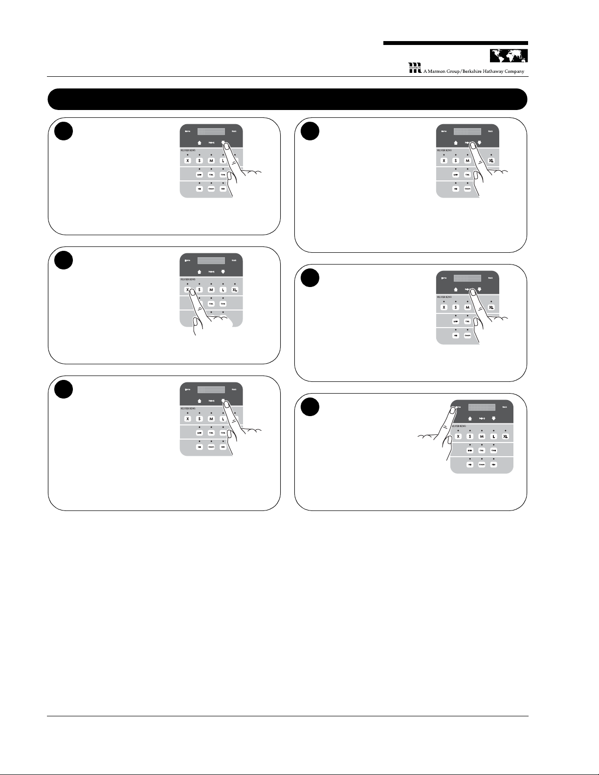
Resetting Factory Defaults
All data and adjustments will be reset to from-the-factory status.
CAUTION
Enter the Manager Level.
On the display panel, press the Up or Down arrow until
Manager Mode is displayed. Press the “X” button in the
Size row.
Manager Mode
Entr Btn Combo
1
Enter the Service Level.
Press the Up or Down arrow until Service Menu is
displayed. Press the Setup Code, which is “X” + “Cap.”
+ “XL”.
NOTE: If the code is not entered correctly, press the
Up arrow once and then the Down arrow once and reenter the code.
Service Menu
Etr Setup Code
2
Reset to factory defaults.
Press the Down arrow to the Factory Default screen
and press Select.
Service Menu
Factory Default
3
Model SKBD3LS
808-004-EN 5 Printed in USA 10/13 © 2013
Page 6
3-Product Dairy Dispenser
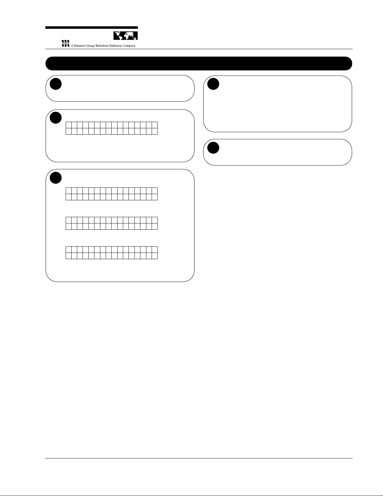
Setting Time and Date
Navigate to the
Manager Level. On
the display panel,
press the Down arrow
until Manager Mode is
displayed.
1
Press the “X”
button. The
“Manager Button
Combination” is the
“X” button in the Size
row.
2
Navigate to the
screen. Press the
Down arrow until the
Set Date/Time screen
is displayed.
3
Adjust the date and
time. Press Select to
begin the adjustment,
then use display panel
buttons to make
changes:
• Use the Home
button to tab right.
• Use the Back
button to tab left.
• Use the Up and Down arrows to change the values.
4
Press Select to
accept the changes.
5
Return to normal
operation. Press the
Home button to return
to the main menu.
6
Model SKBD3LS
P
RINC
E
C
A
STL
E
LLC
WORLDWIDE
Printed in USA 10/13 © 2013 6 808-004-EN
Page 7

3-Product Dairy Dispenser
P
RINC
E
C
A
STL
E
LLC
WORLDWIDE
Calibrating the Unit / Adjusting Shot Size
NOTE: Unit must be calibrated before the unit is put into
operation and as needed thereafter to ensure that the unit is
dispensing within the required specifications.
Exercise the tubes. If unit has been idle (no shots
taken for over a half hour) take one shot of size Medium
(coffee) for each product to exercise the tubes.
1
Place a cup on the external scale and press tare.
2
Dispense a shot.
Press the button of the
product to be
dispensed, place the
cup under the proper
product tube, and then
press the “M” button to
dispense product
amount for a medium
coffee.
1
2
3
Weigh the product on the external scale. If the shot
weight is within the specified range listed in the Shot
Size Targets (41 - 51 g), then you can move on to the
next product. If the shot weight is outside of the
specified range, then a simple calibration is required. To
calibrate the unit, follow Steps 5 to 9.
4
Repeat Step 2.
5
Go to the
Calibration menu.
Press the Down arrow
once.
6
Dispense a shot.
NOTE: Make sure the
cup is under the valve
at this time, because
a medium sized shot
is dispensed.
The display now reads
“Calibrate Disp Select
Product”. Press the
button of the product
you wish to calibrate
(Milk, Cream or Skim)
and then press the “M”
button.
e e l l e e c c t t P P o o d d u u c c t t r r
C C a a l l i i b b r r a a t t D i i s s p p e e
S S
1
2
7
Weigh the cup on the external scale.
8
Enter the weight.
The display now reads
“Enter Weight 46
Grams”. Press the Up
or Down arrow until
the value on the
display matches the
weight that you
measured using the
external scale and
then press Select.
4 4 6 G G r r a a m m s s
E E n n t t e e r r W W e e g g h t t i i
1
2
9
Calibrate the next
product. The display
again reads “Calibrate
Disp Select Product”.
You may now select
the next product to
calibrate or press the
Home button to return
to normal operation.
e e l l e e c c t t P P o o d d u u c c t t r r
C C a a l l i i b b r r a a t t D i i s s p p e e
S S
or
10
Model SKBD3LS
808-004-EN 7 Printed in USA 10/13 © 2013
Page 8

3-Product Dairy Dispenser
Shot Size Targets
With machine set to COFFEE
Base
ALL SHOTS ARE LISTED AND MEASURED IN GRAMS
MIN TARGET MAX
COFFEE XS
13 15 17
SM
27 31 34
MED
41 46 51
LG
54 61 67
XLG
68 76 84
LATTE SM
164 183 202
MED
247 275 303
LG
329 367 404
CAPPUCCINO SM
109 122 135
MED
164 183 202
LG
219 244 269
COOLATTA XS
54 61 67
SM
109 122 135
MED
163 183 202
LG
217 243 269
With machine set to NEUTRAL
Base
ALL SHOTS ARE LISTED AND MEASURED IN GRAMS
MIN TARGET MAX
COFFEE XS
13 15 17
SM
27 31 34
MED
41 46 51
LG
54 61 67
XLG
68 76 84
LATTE SM
164 183 202
MED
247 275 303
LG
329 367 404
CAPPUCCINO SM
109 122 135
MED
164 183 202
LG
219 244 269
COOLATTA XS
41 46 50
SM
82 91 100
MED
123 137 150
LG
164 182 200
Model SKBD3LS
P
RINC
E
C
A
STL
E
LLC
WORLDWIDE
Printed in USA 10/13 © 2013 8 808-004-EN
Page 9
3-Product Dairy Dispenser
P
RINC
E
C
A
STL
E
LLC
WORLDWIDE
Updating and Exporting Files
Remove the plug covering the USB port and attach
a Flash drive.
1
Enter the Manager Level.
On the display panel, press the Up or Down arrow until
Manager Mode is displayed. Press the “X” button in the
Size row.
Manager Mode
Entr Btn Combo
2
Navigate to the screen. Press the Up or Down arrow
until the appropriate screen appears. Choose:
• Press Select To Update Display to download an
updated display file from a Flash drive.
• Press Select To Update Relay to download an
updated relay file from a Flash drive.
• Export Files To USB to upload files from the unit to
a Flash drive.
Press Select To
Update Display
Press Select To
Update Relay
Export Files
To USB
3
Press Select to initiate the download/upload. A
status message will appear in the display. (If an error
code appears, see Error Messages on page 5.)
• When a download is complete, the screen will
automatically return to the main menu.
• When an upload is complete, the screen will
automatically return to the main menu.
4
Remove the Flash drive and insert the USB port
plug.
5
Model SKBD3LS
808-004-EN 9 Printed in USA 10/13 © 2013
Page 10

3-Product Dairy Dispenser
Changing Set Point, Base, Low Product Thresholds, Beeper Status
Enter the Manager Level.
On the display panel, press the Up or Down arrow until
Manager Mode is displayed. Press the “X” button in the
Size row.
Manager Mode
Entr Btn Combo
1
Navigate to the screen and change settings. Press
the Up or Down arrow until the appropriate screen
appears. Choose:
A. Manager Mode Temp Set Pt: XX to change the
unit’s set point.
1. Press Select to initiate the change.
2. Press the Up or Down arrow to choose the
desired temperature (between 35 and 40°F).
3. Press Select again to accept the change.
B. Manager Mode Base Select to change to “coffee”
or “neutral” Coolatta base.
1. Press Select to initiate the change.
2. Press the Up or Down arrow to choose the
correct term.
3. Press Select again to accept the change.
C. Set Low Mlk/Skm Threshold or Set Low Cream
Threshold to change the amount at which the unit
goes into lockout (will not dispense).
1. Press Select to initiate the change.
2. Press the Up or Down arrow to change the
amount in increments of 50 g. Default Milk and
Skim levels are 600 g and the default Cream
level is 850 g.
3. Press Select again to accept the change.
D Manager Mode Beeper On (or Off) to enable/
disable the audible alarm.
1. Press Select to initiate the change.
2. Press the Up or Down arrow to toggle between
On and Off.
3. Press Select again to accept the change.
Manager Mode
Temp Set Pt: XX
Manager Mode
Base Select
Set Low Mlk/Skm
Threshold: XXXX
Manager Mode
Beeper XX
2
Press the Home button to return to the main menu
or choose another setting to change.
3
Model SKBD3LS
Printed in USA 10/13 © 2013 10 808-004-EN
P
RINC
E
C
A
STL
E
LLC
WORLDWIDE
Page 11

3-Product Dairy Dispenser
P
RINC
E
C
A
STL
E
LLC
WORLDWIDE
Zeroing Out the Load Cells
When replacing a control board (p/n 36992S) or load cell (p/n
37168S) it will be necessary to zero out the load cells. Please
carefully follow each step of the load cell calibration instructions
listed below.
IMPORTANT
Power up the unit. Connect the power cord to a
115 VAC outlet. Turn the unit on and wait while the
controller initiates.
1
Remove all product tanks from the unit. Make sure
nothing is on any of the load cells.
2
Press Home on the display panel.
3
Enter the Manager Menu.
Press the Up or Down arrow until Manager Mode is
displayed. Press the “X” button in the Size row.
Manager Mode
Entr Btn Combo
4
Enter the Service Menu.
Press the Up or Down arrow until Service Menu is
displayed. Press the Setup Code, which is “X” + “Cap.”
+ “XL”.
NOTE: If the code is not entered correctly, press the
Up arrow once and then the Down arrow once and reenter the code.
Service Menue
Etr Setup Code
5
Press Select 3 times. A “Calibration Done” message
will appear on the display.
6
Press the Home button to return to the main menu.
7
Load the tanks and product back into the machine.
8
Follow the instructions under Calibrating the Unit /
Adjusting Shot Size.
9
Model SKBD3LS
808-004-EN 11 Printed in USA 10/13 © 2013
Page 12

3-Product Dairy Dispenser
Viewing Other Load Cell Data
Enter the Manager Menu.
Press the Up or Down arrow until Manager Mode is
displayed. Press the “X” button in the Size row.
Manager Mode
Entr Btn Combo
1
Enter the Service Menu.
Press the Up or Down arrow until Service Menu is
displayed. Press the Setup Code, which is “X” + “Cap.”
+ “XL”.
NOTE: If the code is not entered correctly, press the
Up arrow once and then the Down arrow once and reenter the code.
Service Menu
Etr Setup Code
Service Menu
Load Cells
2
Press Select.
3
Navigate to the screen and view data. Press the Up
or Down arrow until the appropriate screen appears.
Choose:
A. Load Cell Counts to view the activation count.
B. Calibration Zero to view Load Cell 1 zero, Load
Cell 2 zero and Load Cell 3 zero.
C. Calibration Span to view Load Cell 1 span, Load
Cell 2 span and Load Cell 3 span.
4
Press the Home button to return to the main menu.
5
Solenoids – Test Cycling/Viewing Status
Enter the Manager Menu.
Press the Up or Down arrow until Manager Mode is
displayed. Press the “X” button in the Size row.
Manager Mode
Entr Btn Combo
1
Enter the Service Menu.
Press the Up or Down arrow until Service Menu is
displayed. Press the Setup Code, which is “X” + “Cap.”
+ “XL”.
NOTE: If the code is not entered correctly, press the
Up arrow once and then the Down arrow once and reenter the code.
Service Menu
Etr Setup Code
Service Menu
Load Cells
2
Navigate to the Service Menu Solenoids screen.
Press the Up or Down arrow until the screen appears.
Service Menu
Solenoids
3
Press Select.
4
Navigate to the desired screen (Milk Solenoid,
Cream Solenoid, Skim Solenoid).
Press the Down arrow until the appropriate screen
appears.
Milk Solenoid
S=ON L=OFF
5
Cycle the solenoid.
A. Use the “S” button on the display to turn on the
solenoid.
B. Use the “L” button on the display to turn off the
solenoid.
C. Use the Down arrow to move on to the next screen.
NOTE: After the Skim Solenoid screen are lifetime
cycle counts for the three solenoids.
Milk Sol. Cyl.
XXXX
6
Press the Home button to return to the main menu.
7
Model SKBD3LS
P
RINC
E
C
A
STL
E
LLC
WORLDWIDE
Printed in USA 10/13 © 2013 12 808-004-EN
Page 13

3-Product Dairy Dispenser
P
RINC
E
C
A
STL
E
LLC
WORLDWIDE
Compressor – Test Cycling/Setting Up
Enter the Manager Menu.
Press the Up or Down arrow until Manager Mode is
displayed. Press the “X” button in the Size row.
Manager Mode
Entr Btn Combo
1
Enter the Service Menu.
Press the Up or Down arrow until Service Menu is
displayed. Press the Setup Code, which is “X” + “Cap.”
+ “XL”.
NOTE: If the code is not entered correctly, press the
Up arrow once and then the Down arrow once and reenter the code.
Service Menu
Etr Setup Code
Service Menu
Load Cells
2
Navigate to the Service Menu Temp/Compressor
screen. Press the Up or Down arrow until the screen
appears.
Service Menu
Temp/Compressor
3
Press Select.
4
Navigate to the screen and change settings. Press
the Up or Down arrow until the appropriate screen
appears. Choose:
A. Temp/Compressor/Short Cycle Timer to change
the compressor’s timer.
1. Press Select to initiate the change.
2. Press the Up or Down arrow to choose the
desired time in minutes.
3. Press Select again to accept the change.
B. Temp/Compressor/Temp Offset to change the
temperature offset between probe and display.
1. Press Select to initiate the change.
2. Press the Up or Down arrow to choose the offset.
3. Press Select again to accept the change.
C. Temp/Compressor/Temp Diff to change the
compressors’ temperature differential between set
point and cutout.
1. Press Select to initiate the change.
2. Press the Up or Down arrow to change the
differential.
3. Press Select again to accept the change.
D. Compressor S = ON L = OFF to force the
compressor ON/OFF.
1. Press Select to initiate the change.
2. Press the “S” on the display to turn the
compressor on or press the “L” on the display to
turn the compressor off.
3. Press Select again to accept the change.
Temp/Compressor
Scycle Timer: XX
Temp/Compressor
Temp Offset XX
Temp/Compressor
Temp Diff: XX
Compressor
S=ON L=OFF
5
Press the Home button to return to the main menu
or choose another setting to change.
6
Model SKBD3LS
808-004-EN 13 Printed in USA 10/13 © 2013
Page 14

3-Product Dairy Dispenser
Troubleshooting Guide
Model SKBD3LS
PROBLEM PROBABLE CAUSE SOLUTION
Not dispensing accurately Containers not in correct position Check container position (L,C,R).
Wrong tubes being used Use Silver King tubes only (Part No. 37222).
Unit out of calibration Run daily calibration (See Calibrating the Unit).
Valve hanging up Replace valve.
Not dispensing Container empty Fill container.
Bad relay Replace relay.
Bad solenoid Replace solenoid.
Poor connect to solenoid Check connection.
Broken valve Replace valve.
Buttons not responding Replace door.
“CHECK (Product name) LC” is
displayed
“EMPT” is displayed when
container is full
Display is blank Unit not receiving power Check that service cord is firmly connected to the wall socket and
Unit will not stop dispensing Bad relay Replace relay.
Ice buildup Door not sealing Check that door is properly closed. Close the tank covers, the top
Bad connection Replace load cell.
Bad terminal board Replace terminal board.
Unit needs to be zeroed See Zeroing Out the Load Cells.
Bad load cell Replace load cell.
the unit, and the power switch is in the “ON” position.
Door cable Check door cable to make sure it is secure. If secure, replace
cable.
Bad power supply Replace power supply.
Bad display Replace door.
Bad valve Replace valve.
Bad solenoid Replace solenoid.
access door, and then the front door of the unit. NOTE: Closing
front door before top access can create a gap which may lead to
increased ice buildup and/or warm dairy product.
Bad gasket Replace gasket.
Bad temperature probe Replace probe.
P
RINC
E
C
A
STL
E
LLC
WORLDWIDE
Printed in USA 10/13 © 2013 14 808-004-EN
Page 15

3-Product Dairy Dispenser
P
RINC
E
C
A
STL
E
LLC
WORLDWIDE
Accessing/Servicing Components from the Front
Door-Display Connector Cable • Door Assembly, Door Gasket • Temperature Probe
• Valve Plunger Assemblies • Solenoids, Solenoid Rack Assembly • Control Board
• Relays • Terminal Board • Power Supply • Load Cell Assemblies
Risk of Electric Shock.
Always unplug the power cord before servicing the unit to
avoid electric shock.
WARNING
Silver King tubes (Part No. 37222) must be on order for this unit.
Be sure to have 3 clamps available to manually close the tubes
for any service activity that may require opening the product
valves while the tanks contain product. Office supply binder clips
work well.
IMPORTANT
Turn off the power
switch and
unplug the unit.
The power switch is
on the left side of
the unit near the
front.
1
Uninstall the cup guide and the drip tray.
Cup Guide
Drip Tray
Mount
Drip Tray
Mount
2
Remove the panel. Remove the 4 screws and remove
the lower front panel.
3
Model SKBD3LS
808-004-EN 15 Printed in USA 10/13 © 2013
Page 16

3-Product Dairy Dispenser
Accessing/Servicing Components from the Front (continued)
G
H
I
J
A
B
C
D
F
E
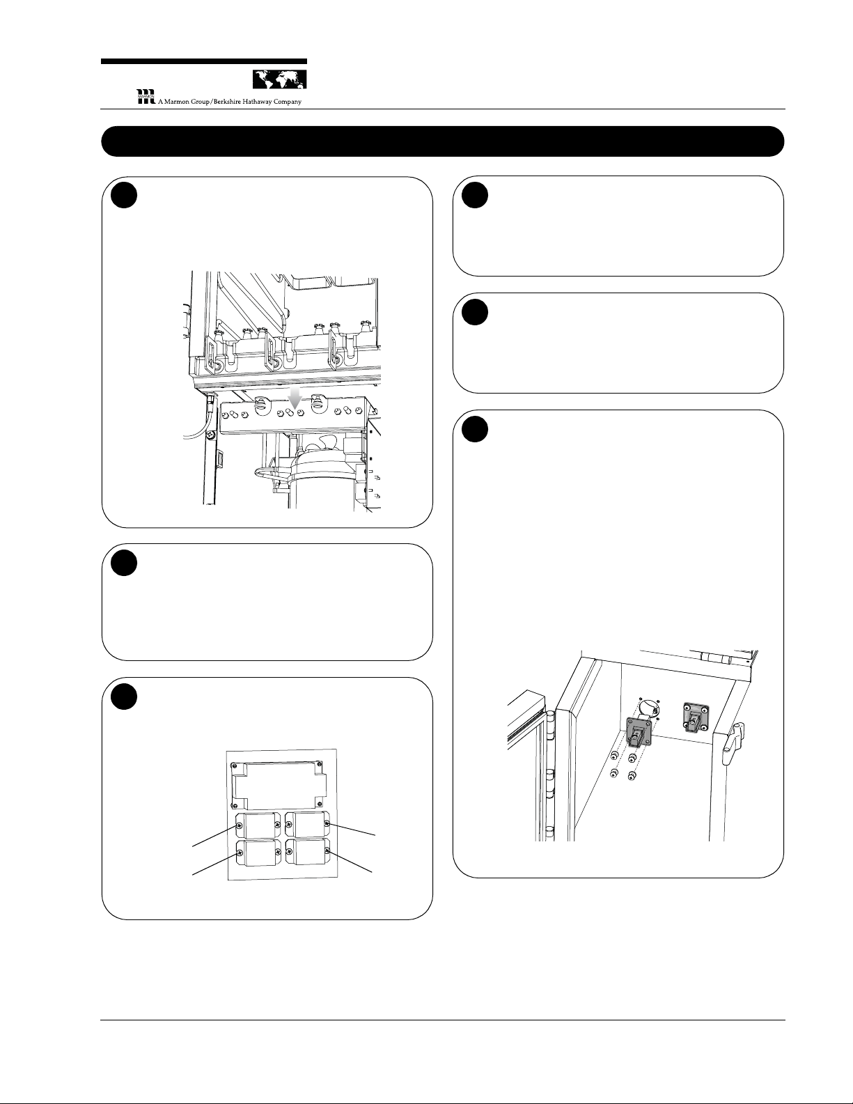
Door-Display
Connector Cable.
Always ensure the
connections are
secure.
Replace by handtightening the
threaded connectors.
A
Door Assembly, Door Gasket.
The display is part of the door assembly.
B
Temperature Probe.
The temperature probe is behind a shield in the right
rear of the tank cavity.
C
Valve Plunger Assemblies.
If a valve is not working, take an ohm reading at the clip
disconnect.
D
Model SKBD3LS
P
RINC
E
C
A
STL
E
LLC
WORLDWIDE
Printed in USA 10/13 © 2013 16 808-004-EN
Page 17
3-Product Dairy Dispenser
P
RINC
E
C
A
STL
E
LLC
WORLDWIDE
Accessing/Servicing Components from the Front (continued)
Solenoids, Solenoid Rack Assembly.
Solenoids can be replaced individually. To remove the
solenoid rack assembly, loosen the two captured
screws and pull the rack down.
E
Control Board.
The control board simply slides out from the control
assembly.
After replacing the control board, it will be necessary to
zero out the load cells for proper operation. Follow the
instructions, Zeroing Out the Load Cells.
F
Relays.
To better access the relays, loosen the 2 nuts that
attach the control assembly to the unit and remove the
whole control assembly.
Center
(Cream)
Compressor
Right
(Skim)
Left
(Milk)
G
Terminal Board.
To better access the terminal board, loosen the 2 nuts
that attach the control assembly to the unit and remove
the whole control assembly.
The terminal board is labeled for each connection.
H
Power Supply.
To better access the power supply, loosen the 2 nuts
that attach the control assembly to the unit and remove
the whole control assembly.
I
Load Cell Assemblies.
To remove a load cell:
1. Access the unit from both the front and rear.
2. At the front, disconnect the load cell connector
from the terminal board.
3. Cut the wire tie.
4. Remove the 4 screws that hold the assembly.
5. Pull the load cell through the load cell mounting
hole, making sure to guide the cable through
carefully from the rear to prevent cutting the load
cell cable insulation.
To install a load cell, reverse the removal process.
After replacing a load cell, it will be necessary to zero
out the load cells for proper operation. Follow the
instructions, Zeroing Out the Load Cells.
J
Model SKBD3LS
808-004-EN 17 Printed in USA 10/13 © 2013
Page 18

3-Product Dairy Dispenser
Accessing/Servicing Components from the Rear
Fan Assembly • Compressor Start Components • Compressor • Load Cell Assemblies
Risk of Electric Shock.
Always unplug the power cord before servicing the unit to
avoid electric shock.
WARNING
Silver King tubes (Part No. 37222/DCP SKU 711490) must be
used for this unit. Be sure to have 3 clamps available to manually
close the tubes for any service activity that may require opening
the product valves while the tanks contain product. Office supply
binder clips work well.
IMPORTANT
Turn off the power
switch and
unplug the unit.
The power switch is
on the left side of
the unit near the
front.
1
Remove the panel(s). Remove the 8 screws and
remove the main rear panel. To access the load cell
assemblies, remove the 4 screws and remove the load
cell access panel.
2
Model SKBD3LS
P
RINC
E
C
A
STL
E
LLC
WORLDWIDE
Printed in USA 10/13 © 2013 18 808-004-EN
Page 19
3-Product Dairy Dispenser
P
RINC
E
C
A
STL
E
LLC
WORLDWIDE
Accessing/Servicing Components from the Rear (continued)
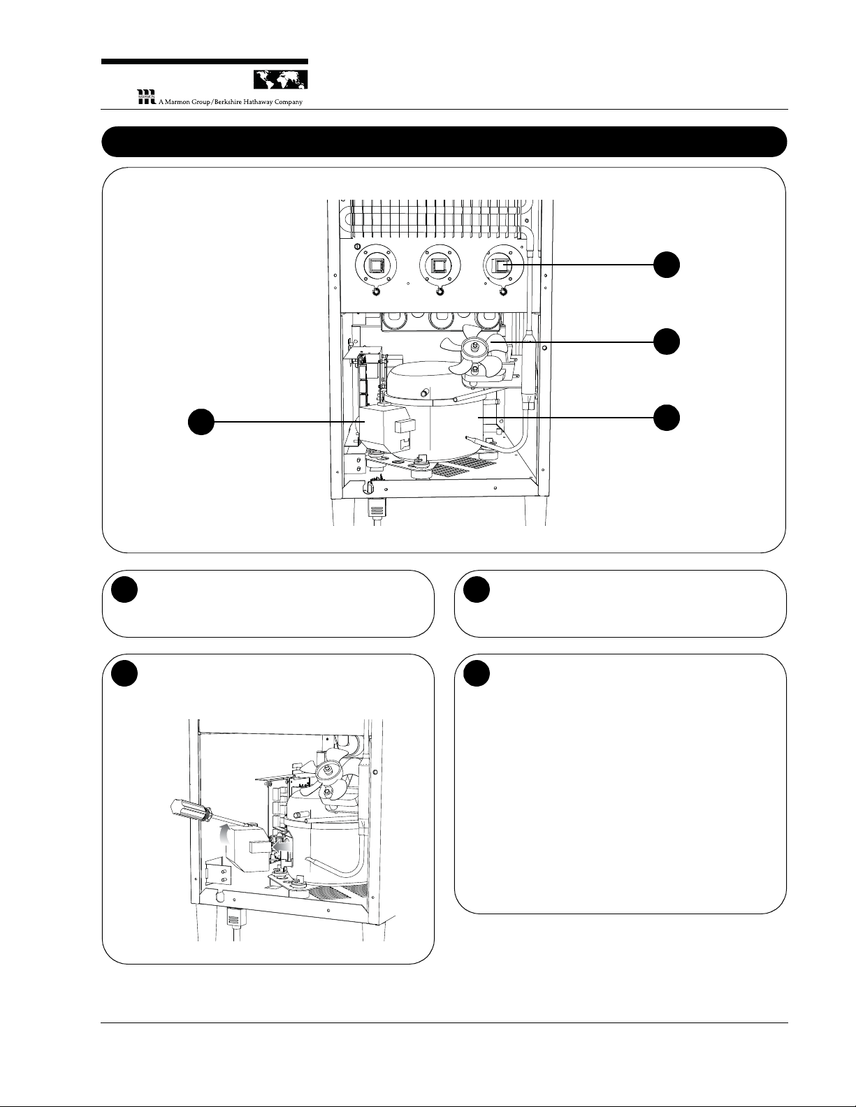
D
A
B
C
Fan Assembly.
Without accessing, a non-working fan is evident when
no air is flowing out of the top rear of the unit.
A
Compressor Start Components.
To access the overload and start relay, pop off the gray
cover.
B
Compressor.
The compressor is a closed system. To service the
compressor, a service valve must be provided.
C
Load Cell Assemblies.
To remove a load cell:
1. Access the unit from both the front and rear.
2. At the front, disconnect the load cell connector
from the terminal board.
3. Cut the wire tie.
4. Remove the 4 screws that hold the assembly.
5. Pull the load cell through the load cell mounting
hole, making sure to guide the cable through
carefully from the rear to prevent cutting the load
cell cable insulation.
To install a load cell, reverse the removal process..
After replacing a load cell, it will be necessary to zero
out the load cells for proper operation. Follow the
instructions, Zeroing Out the Load Cells.
D
Model SKBD3LS
808-004-EN 19 Printed in USA 10/13 © 2013
Page 20
3-Product Dairy Dispenser
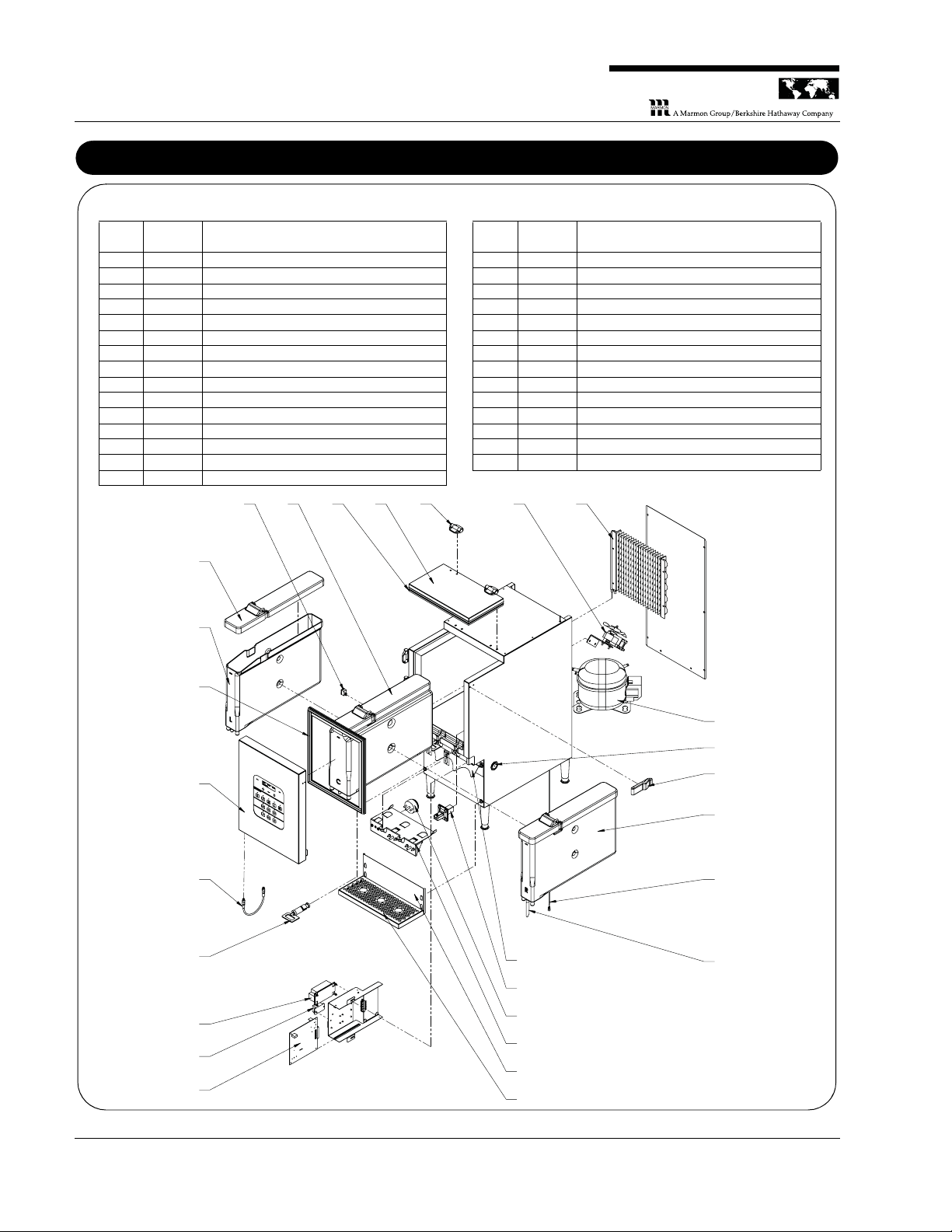
Parts List and Exploded View
NOTE: To order Parts/Service, Contact Silver King Refrigeration at 800-328-3329 for technical assistance.
Item NoPart
No Description
1 25226S Hinge w/Screws & Covers
2 25227S Latch
3 36954S Lid Gasket SKBD3LS
4 36955S Lid Assembly SKBD3LS
5 36956S Door Gasket SKBD3LS
6 36957S Door Assembly SKBD3LS
7 36992S Control Board
8 37016S Condenser Coil SKBD3LS
9 37052S Platform for Drip Tray
10 37068S Container Assembly Left
11 37069S Container Assembly Center
12 37070S Container Assembly Right
13 811-006S Lid, Container SKBD3LS
14 37133S Valve Plunger Assembly
15 37146S Power Supply
16 37147S Relay
17 37461S Solenoid Rack Assembly
18 37168S Load Cell Assembly SKBD3LS
19 37202S Fan Assembly SKBD3LS
20 37210S Connector, Door-Display SKBD3LS
21 37222 3" Tubes (Carton of 300)
22 37239S Rocker Switch SKBD3LS
23 37281S Drip Tray SKBD3LS
24 37364S Probe Temp SKBD3LS
25 37436S Upper Cup Guide
26 37485S Solenoid
27 10343-02 Compressor 115V/60HZ EMI30HER
10344-02 Electricals - Compressor
28 37358S USB Hole Plug - 1" Dia
Item NoPart
No Description
22 11 3 4 1 19 8
6
5
13
10
20
7
14
15
16
18
26
17
21
24
12
2
28
27
9
23
25
Model SKBD3LS
P
RINC
E
C
A
STL
E
LLC
WORLDWIDE
Printed in USA 10/13 © 2013 20 808-004-EN
Page 21
3-Product Dairy Dispenser
P
RINC
E
C
A
STL
E
LLC
WORLDWIDE
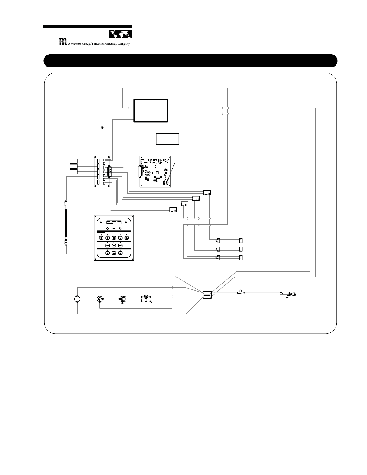
Wiring Diagram
POWER
SUPPLY
4
3
2
1
LOAD CELLS
LEFT
CENTER
TEMP
SENSOR
BATTERY
CR2032H
CONTROL
BOARD
DATA
CABLE
TO
DOOR
CONNECTOR
BOARD
DISPLAY
#1
#2
#3
COMPRESSOR
RELAY
SOLENOIDS
POWER
SWITCH
TERMINAL
BLOCK
COND
FAN
COMP
OVERLOAD
RELAY
RED
WHITE
WHITE
SOLENOID
RELAYS
POWER CORD
115V/60HZ
BLACK
WHITE
SKBD3LS
36946
REV: B
RED
#1 LEFT
#2 CENTER
#3 RIGHT
GROUND
120V AC
IN
BLACK
(-)
RED (+)
#1
#2
#3
GROUND
RED
AS VIEWED
FROM FRONT
OF MACHINE
AS VIEWED
FROM FRONT
OF MACHINE
←
24V DC
OUT
RIGHT
RED (+)
BLACK
(-)
RED
WHITE
RED
FUSE
T10AL250VP
RED
WHITE
GRAY
BLACK
BLUE
BLUE
BROWN
BLUE
BROWN
BROWN
BROWN
BLUE
WHITE
WHITE
RED
RED
RED
BLACK
BLACK
BLACK
Model SKBD3LS
808-004-EN 21 Printed in USA 10/13 © 2013
 Loading...