

Page 1
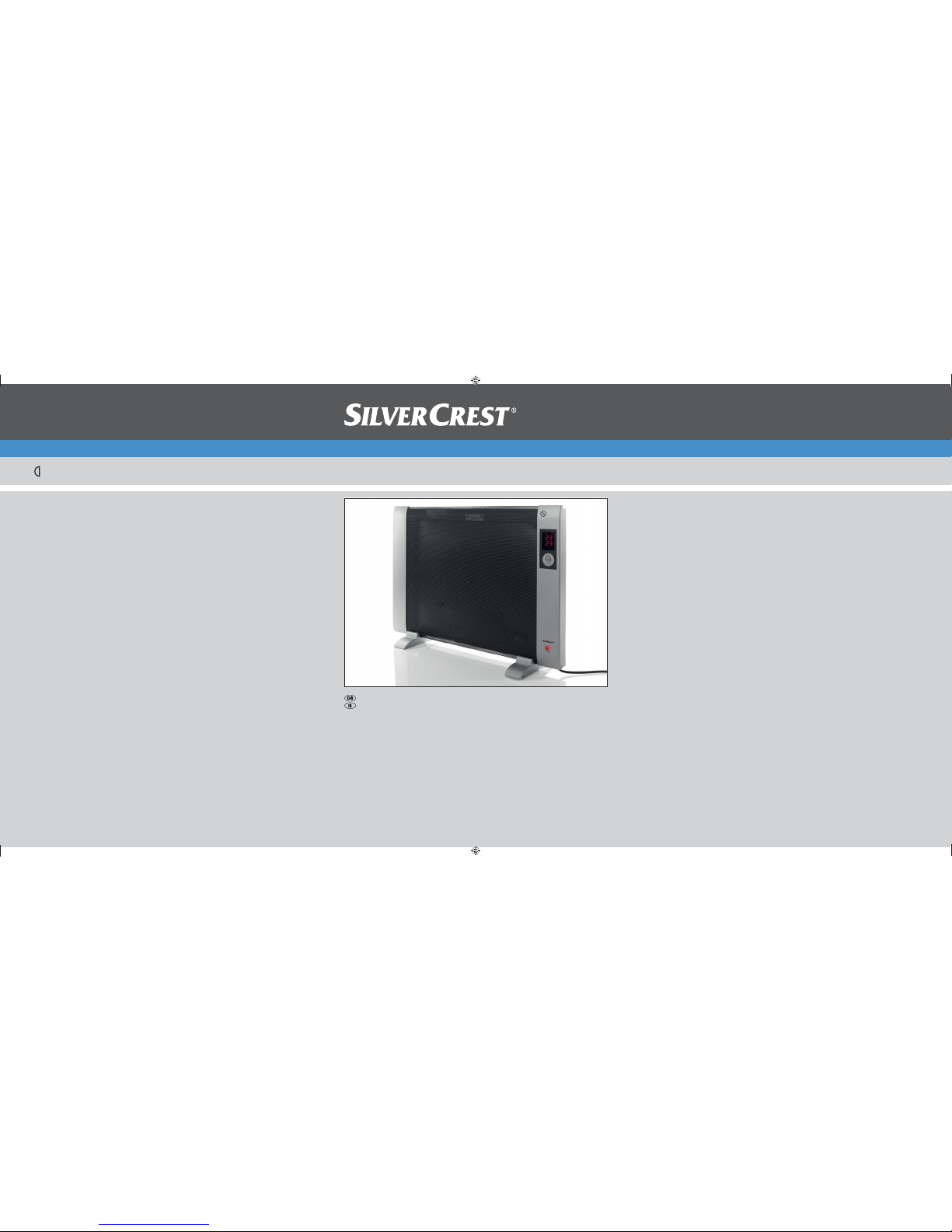
Wave Heater SWW 1500 A1
6
KOMPERNASS GMBH
BURGSTRASSE 21 · D-44867 BOCHUM
www.kompernass.com
ID-Nr.: SWW 1500 A1-05/11-V3
IAN: 66900
Wave Heater
Operating instructions
CV_66900_SWW1500A1_LB6.indd 1-3CV_66900_SWW1500A1_LB6.indd 1-3 25.07.2011 11:15:13 Uhr25.07.2011 11:15:13 Uhr
Page 2
SWW 1500 A1
7
6
9 0
8
q
w
r
e
t
1
2
3
4
5
CV_66900_SWW1500A1_LB6.indd 4-6CV_66900_SWW1500A1_LB6.indd 4-6 25.07.2011 11:15:14 Uhr25.07.2011 11:15:14 Uhr
Page 3

Index
Introduction . . . . . . . . . . . . . . . . . . . . . . . . . . . . . . . . . . . . . . . . . . . . . . . . . . . 2
Information regarding these operating instructions . . . . . . . . . . . . . . . . . . . . . . . . . . . . . . . 2
Copyright . . . . . . . . . . . . . . . . . . . . . . . . . . . . . . . . . . . . . . . . . . . . . . . . . . . . . . . . . . . . . . . 2
Limited liability . . . . . . . . . . . . . . . . . . . . . . . . . . . . . . . . . . . . . . . . . . . . . . . . . . . . . . . . . . . 2
Warnings . . . . . . . . . . . . . . . . . . . . . . . . . . . . . . . . . . . . . . . . . . . . . . . . . . . . . . . . . . . . . . . 3
Intended use . . . . . . . . . . . . . . . . . . . . . . . . . . . . . . . . . . . . . . . . . . . . . . . . . . . . . . . . . . . . 4
Safety. . . . . . . . . . . . . . . . . . . . . . . . . . . . . . . . . . . . . . . . . . . . . . . . . . . . . . . . 4
Risks from electrical current . . . . . . . . . . . . . . . . . . . . . . . . . . . . . . . . . . . . . . . . . . . . . . . . . 4
Basic Safety Instructions. . . . . . . . . . . . . . . . . . . . . . . . . . . . . . . . . . . . . . . . . . . . . . . . . . . . 5
Initial use . . . . . . . . . . . . . . . . . . . . . . . . . . . . . . . . . . . . . . . . . . . . . . . . . . . . . 6
Package contents and transport inspection . . . . . . . . . . . . . . . . . . . . . . . . . . . . . . . . . . . . . 6
Disposal of the packaging . . . . . . . . . . . . . . . . . . . . . . . . . . . . . . . . . . . . . . . . . . . . . . . . . . 6
Requirements for the set-up location . . . . . . . . . . . . . . . . . . . . . . . . . . . . . . . . . . . . . . . . . . 7
Before initial use . . . . . . . . . . . . . . . . . . . . . . . . . . . . . . . . . . . . . . . . . . . . . . . . . . . . . . . . . 7
Electrical connection . . . . . . . . . . . . . . . . . . . . . . . . . . . . . . . . . . . . . . . . . . . . . . . . . . . . . . 8
Inserting batteries into the remote control . . . . . . . . . . . . . . . . . . . . . . . . . . . . . . . . . . . . . . 8
Operating components . . . . . . . . . . . . . . . . . . . . . . . . . . . . . . . . . . . . . . . . . . 8
Assembly . . . . . . . . . . . . . . . . . . . . . . . . . . . . . . . . . . . . . . . . . . . . . . . . . . . . . 9
Stationary assembly. . . . . . . . . . . . . . . . . . . . . . . . . . . . . . . . . . . . . . . . . . . . . . . . . . . . . . . 9
Wall mounting . . . . . . . . . . . . . . . . . . . . . . . . . . . . . . . . . . . . . . . . . . . . . . . . . . . . . . . . . . . 9
GB
IE
Handling and operation . . . . . . . . . . . . . . . . . . . . . . . . . . . . . . . . . . . . . . . . 11
Switching the device on and off . . . . . . . . . . . . . . . . . . . . . . . . . . . . . . . . . . . . . . . . . . . . 11
Heating operation . . . . . . . . . . . . . . . . . . . . . . . . . . . . . . . . . . . . . . . . . . . . . . . . . . . . . . . 11
Setting the nominal temperature . . . . . . . . . . . . . . . . . . . . . . . . . . . . . . . . . . . . . . . . . . . . 12
Programming the switch off time . . . . . . . . . . . . . . . . . . . . . . . . . . . . . . . . . . . . . . . . . . . . 12
Programming the switch on time . . . . . . . . . . . . . . . . . . . . . . . . . . . . . . . . . . . . . . . . . . . . 12
Overheating protection . . . . . . . . . . . . . . . . . . . . . . . . . . . . . . . . . . . . . . . . . . . . . . . . . . . 13
Frost protection function . . . . . . . . . . . . . . . . . . . . . . . . . . . . . . . . . . . . . . . . . . . . . . . . . . . 13
Topple over protection . . . . . . . . . . . . . . . . . . . . . . . . . . . . . . . . . . . . . . . . . . . . . . . . . . . . 13
Cleaning . . . . . . . . . . . . . . . . . . . . . . . . . . . . . . . . . . . . . . . . . . . . . . . . . . . . 14
Storage . . . . . . . . . . . . . . . . . . . . . . . . . . . . . . . . . . . . . . . . . . . . . . . . . . . . . 14
Disposal . . . . . . . . . . . . . . . . . . . . . . . . . . . . . . . . . . . . . . . . . . . . . . . . . . . . . 14
Troubleshooting . . . . . . . . . . . . . . . . . . . . . . . . . . . . . . . . . . . . . . . . . . . . . . 15
Malfunction causes and remedies . . . . . . . . . . . . . . . . . . . . . . . . . . . . . . . . . . . . . . . . . . . 15
Appendix . . . . . . . . . . . . . . . . . . . . . . . . . . . . . . . . . . . . . . . . . . . . . . . . . . . . 16
Technical data . . . . . . . . . . . . . . . . . . . . . . . . . . . . . . . . . . . . . . . . . . . . . . . . . . . . . . . . . . 16
Information regarding the EG conformity declaration . . . . . . . . . . . . . . . . . . . . . . . . . . . 16
Warranty . . . . . . . . . . . . . . . . . . . . . . . . . . . . . . . . . . . . . . . . . . . . . . . . . . . . . . . . . . . . . . 17
Service . . . . . . . . . . . . . . . . . . . . . . . . . . . . . . . . . . . . . . . . . . . . . . . . . . . . . . . . . . . . . . . . 17
Importer . . . . . . . . . . . . . . . . . . . . . . . . . . . . . . . . . . . . . . . . . . . . . . . . . . . . . . . . . . . . . . . 17
SWW 1500 A1
1
Page 4

Introduction
GB
IE
Introduction
Information regarding these operating instructions
These operating instructions are a component of the Thermal wave heater
SWW 1500 A1 (subsequently refered to as the device) and provide you with
important information for proper use, safety, connections as well as operation of
the device.
These operating instructions must be constantly kept available close to the device.
They are to be read and applied by anyone assigned to operate, and/or repair
faults to the device.
Retain these operating instructions and pass them on, together with the device, to
any future owners.
Copyright
This documentation is copyright protected.
Any copying and/or reproduction, wholly or partially, including reproduction of
the illustrations, also in a modifi ed format is only permitted with written consent
from the manufacturer.
Limited liability
All technical information, data and instructions for the installation, connection
and operation contained in these operating instructions correspond to the latest
available at the time of printing and, to the best of our knowledge, take into
account our previous experience and know-how.
No claims can be derived from the details, illustrations and descriptions in these
instructions.
The manufacturer assumes no responsibility for damage caused by failure to observe
the instructions, improper use, inappropriate repairs, making unauthorised changes
or for using unauthorised replacement parts.
2
SWW 1500 A1
Page 5
Introduction
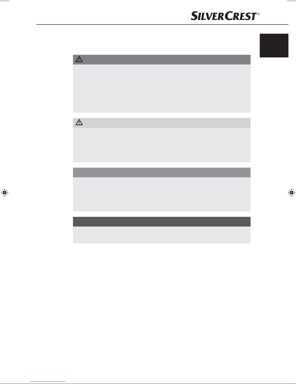
Warnings
In the current operating instructions the following warnings are used:
A warning of this danger level indicates a life-threatening
danger
If the dangerous situation is not avoided, it could lead to death or serious
physical injury.
A warning of this danger level signifi es a possible dangerous
situation.
If the dangerous situation is not avoided it could lead to physical injuries.
CAUTION
GB
IE
DANGER
ous situation
Observe the instructions in this warning to avoid the death of or serious ►
physical injury to people.
WARNING
Observe the instructions in this warning to avoid personal injuries. ►
A warning of this danger level signifi es possible pr
damage.
If the situation is not avoided it could lead to property damage.
Observe the instructions in this warning to avoid property damage. ►
NOTICE
A notice signifi es additional information that assists in the handling of the ►
device.
operty
SWW 1500 A1
3
Page 6
Introduction/Safety
GB
IE
Intended use
This device is only intended for heating in indoor living spaces and only for private
purposes. This device can be used free standing or mounted on a wall. This
device is not intended for any other use or for uses beyond those mentioned.
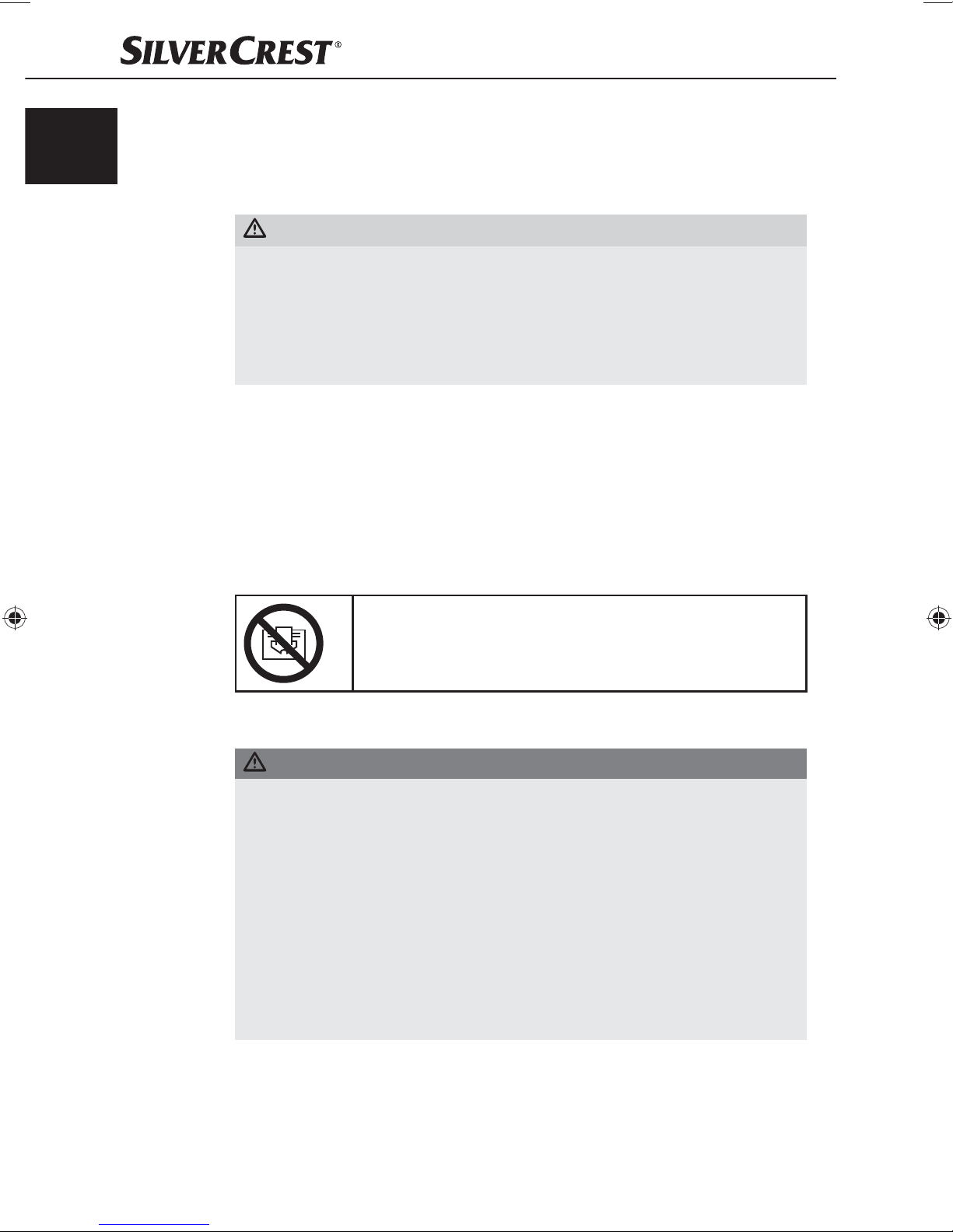
WARNING
Danger from unintended use!
Danger can come from the device if used for unintended purposes and/or
other types of use.
Use the device exclusively for intended purposes. ►
Observe the procedures described in these operating instructions. ►
Claims of any kind for damage resulting from unintended use will not be excepted.
The oper
Safety
In this chapter you will receive important safety information regarding the handling of the device.
This device complies with the statutory safety regulations. Incorrect usage can
lead to personal injury and property damage.
ator alone bear
s liability.
Do not cover the device!
Covering the device can lead to overheating and thus
result in a fi re!
Risks from electrical current
DANGER
Risk of potentially fatal electrical current!
Contact wit
be potentially fatal!
Observe the following safety instructions to avoid risks from electrical current:
Do not use the device if the mains power cord or the plug is damaged. ►
Before putting the device back into service have a new mains power cord ►
installed by an authorised specialist.
Under no circumstances should y
danger of electric shock if voltage carrying connections are touched or the
electrical and/or mechanical construction is changed.
h wires or components that are under voltage could
ou open the device housing. There is a ►
4
SWW 1500 A1
Page 7

Safety
Basic Safety Instructions
For safe handling of the device observe the following safety information:
Before use check the device for visible external damage. Do not put into operation ■
a device that is damaged or has been dropped.
If the device's mains po
the manufacturer's customer service department or by a qualifi ed technician so
that hazards can be pr
This device is not intended for use by individuals (including children) with restricted ■
physical, physiological or intellectual abilities or defi ciences in experience and/
or knowledge unless the
or receive from this person instruction on how the device is to be used.
Children should be supervised to ensure that they do not play with the device. ■
Repairs should only be carried out by authorised specialist companies or by the ■
Customer Service Department. Incompetent repairs can result in signifi cant risks
for the user
A repair to the device during the warranty period may only be carried out by ■
a customer service department authorised by the manufacturer otherwise no
additional warr
. In addition, w
wer cord is damaged, it must be replaced by the manufacturer, ■
evented.
y are supervised by a person responsible for their safety
arranty claims become void.
anty claims can be considered for subsequent damages.
GB
IE
Defective components may only be replaced with original replacement parts. ■
Only by using original replacement parts can it be guaranteed that the safety
requir
ements are being complied with.
Protect the device from moisture and liquid penetration. ■
Always pull the mains power cord from the wall socket by the plug, never pull on ■
the cord.
Do not use the de
The device must not be placed immediately under or over a mains wall socket. ■
In the event of malfunctions and during thunderstorms pull the plug fr
■
mains wall socket.
The device must not be used in the immediate vicinity of a bath, a shower or a ■
swimming pool.
The de
touch the switch and other controls.
Do not subject the device to spr
objects fi lled with liquid, such as vases or open drink containers, on or near the
device.
vice is to be installed so that a per
vice in the vicinit
y of open fl ames. ■
om the
son in the bath or shower is unable to ■
ay and/or dripping water and do not place any ■
SWW 1500 A1
5
Page 8

Initial use
GB
IE
Initial use
Package contents and transport inspection
The device is delivered with the following components as standard:
Thermal wave heater ▯
Remote control ▯
2 Batteries type AAA/Micro ▯
2 Pedestals with securing screws ▯
4 Wall brackets (U shaped) ▯
1 Angle bracket (Z shaped) ▯
5 Rawlplugs S8 ▯
5 Screws M4 x 42 mm ▯
7 Screws M4 x 13 mm ▯
This operating manual ▯
NOTICE
Check the contents to ensure that everything is present and for signs of visible ►
damage.
If the contents are not complete or ar
or through transportation contact the service hotline (see service).
Disposal of the packaging
The packaging protects the device from transport damage. The packaging materials
are selected from the point of view of their environmental friendliness and disposal
technology and are therefore recyclable.
The recirculation of packaging into the material circuit saves on raw material
and reduces generated waste. Dispose of packaging material that is no longer
needed according to the regionally established regulations.
NOTICE
If possible preserve the device's original packaging during the warranty ►
period so that in the case of a warranty claim you can package the device
properly for r
eturn.
e damaged due to defective packaging ►
6
SWW 1500 A1
Page 9

Initial use
Requirements for the set-up location
For safe and faultless operation of the device the set-up location must satisfy the
following criteria:
The device must only be operated in an upright position and completely assembled. ■
When using the pedestals the device must be placed on a fi rm, fl at and even fl oor. ■
When wall mounting the device must only be mounted in a fi xed position on a ■
verticle wall.
The minimum distances of the housing fr
are; 100 mm at the sides, 300 mm above, 150 mm below (with wall mounting)
and 500 mm in front.
Do not stand and/or hang the de
in the vicinity of fl ammable materials.
The mains wall sock
can be easily removed in an emergency.
Envir
onment temperature range: +5 to +45 °C ■
Humidity (no condensation): 5 - 90 % ■
DANGER
et must be easily accessible so that the mains power cord ■
om other objects must be maintained, the
vice in a hot, wet or very moist environment or ■
GB
IE
y ■
Fire hazard through contact with materials!
The risk of fi
with fl ammable materials!
Do not place and/or hang the device in the vicinity of curtains and other ►
fl ammable materials.
Do not allow fl
the device.
Do not cover the device. ►
re exists if the heating elements come into contact
Before initial use
Remove all packaging materials and all transport securing devices from the device. ■
NOTICE
With initial use, for a brief period, a light odour accumulation can occur. ►
This is normal and completely harmless.
ammable materials (i.e. draperies) to come into contact with ►
SWW 1500 A1
7
Page 10

Initial use/Operating components
GB
IE
Electrical connection
For safe and faultless operation of the device with electrical connection observe
the following advice:
CAUTION
Before connecting the device compare the connection data (voltage and ►
frequency) on the rating plate with that of your mains power supply. This
data must be in agreement so as to av
Make sure that the mains power cord is not damaged and is not running ►
over hot surfaces and/or sharp edges.
Make sur
e that the mains power cord is not stretched or knoted. ►
oid damage to the device.
Inserting batteries into the remote control
Open the battery compartment on the rear panel of the remote control. ♦
Insert the batteries, type AAA/Micro into the battery compartment. ♦
Make sure the polarities are correct.
Close the battery compar
tment. ♦
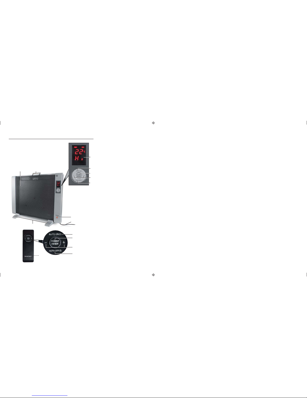
Operating components
Device
Display
2
AUTO ON button
3
POWER/MODE button
4
+/- buttons
5
AUTO OFF button
6
POWER main switch
7
Mains power cord
8
Pedestals
9
Heating element
10
Carrying handle
Remote control
11
AUTO ON button
12
POWER/MODE button
13
+/- buttons
14
AUTO OFF button
15
Battery compartment
8
SWW 1500 A1
Page 11

Assembly
Assembly
CAUTION
For assembly place the device on a soft underlay such as, for example, ►
a carpet in order to avoid damages.
Stationary assembly
Fold the carrying handle ♦
underside upwards, on a soft underlay.
Assemble the pedestals ♦
Pedestal assembly).
A
8
10
backwards and place the device with the
8
with both screws A to the device (see diagram
10
GB
IE
Diagram Pedestal assembly
Wall mounting
WARNING
Make sure that when you are drilling you do not damage any electrical ►
wires or other installations in the wall such as water pipes.
The supplied rawlplugs ar
stone. Before starting the installation, please check your installation location
carefully for its suitability for the rawlplugs. If in doubt, call a professional.
NOTICE
When selecting the mounting location make sure that a suitable mains wall ►
socket is located within the plug-in radius of the mains power cord.
e only suitable for a mounting on concrete or ►
SWW 1500 A1
9
Page 12

Assembly
GB
IE
Slide the upper wall brackets ♦
B
into the holding fi xtures C on the device's
rear panel and fi rmly screw these, together with the angle bracket
the lower wall brackets
B
, to the rear panel of the device. For this purpose
use the 7 screws M4 x 13 mm (see diagram Wall bracket assembly).
C
B
B
D
B
Diagram Wall bracket assembly
Mark two drill holes at a height of 600-650 mm and at a distance of 330 mm. ♦
Mark two more drill holes at a height of 250-300 mm and at a distance of ♦
330 mm. Make sure that the distance between the upper and lower drill
holes is 350 mm (see diagram Drill scheme).
D
and
Now with an electric drill and an 8 mm drill bit drill four holes to a depth of, ♦
at least, 40 mm.
350 mm
600 mm - 650 mm
Diagram Drilling scheme
Insert the rawlplugs into the holes and screw in the M4 x 42 screws. ♦
Allow the screw heads to stick out slightly.
Now hang the de
bracket
D
.
vice on the screws and mark the drill hole for the angle ♦
330 mm
ø 8 mm, 40 mm
250 mm - 300 mm
10
SWW 1500 A1
Page 13

Assembly/Handling and operation
Remove the device from the wall again. With an electric drill and an 8 mm ♦
drill bit drill the hole to a depth of, at least, 40 mm, subsequently insert the
rawlplug into the hole.
Hang the device on the wall and tighten the screw with the angle bracket ♦
(see diagram Tightening the angle bracket).
Diagram Tightening the angle bracket
D
GB
IE
D
+
OW
R
Insert the power plug into a mains wall socket. ♦
Handling and operation
NOTICE
All functions can be switched both with the buttons on the device and with ►
the remote control.
In this section you r
of the device.
Switching the device on and off
With the main switch POWER 6 the device is completely disconnected from the
mains power.
Firstly switch the main switch POWER ♦
no longer operating the device.
Heating operation
Activate the main switch POWER ♦
appears briefl y and subsequently the current device temperature in the
area of the integrated temperature sensor. The device is now in standby
mode. In the display the symbol for the frost protection function blinks.
eceive important information for the handling and operation
6
on and/or lastly off when you are
6
to switch the device on. In the display
Press the button POWER/MODE ♦
with the low heat output (LOW). In the display appears .
Press the button POWER/MODE ♦
output (HIGH). In the display appears .
SWW 1500 A1
3
and/or 12. The device switches on
3
and/or 12 again to set the high heat
11
Page 14

Handling and operation
GB
IE
Setting the nominal temperature
Press the button POWER/MODE ♦
play , the nominal temperature and the indicator LOW blinks for 5 seconds.
Whilst the nominal temperature is blinking in the display ♦
the buttons +/- 4 and/or 13 to set the desired nominal temperature from
15°C to 27°C. Each press of the button +/- 4 and/or 13 increases or
reduces the nominal temperature by 1°C. Wait approx. 5 seconds until the
nominal temperature is continuously shown in the display . The setting is
now saved and the heating element 9 switches on.
Press the button POWER/MODE ♦
high heat output (HIGH). In the display the nominal temperature as well
as the indicator HIGH blink for 5 seconds.
NOTICE
As soon as the temperature at the temperature sensor integrated into the ►
device has reached the set nominal temperature the heating element
switches off and in the display the indicator HIGH and/or LOW blinks.
As soon as the temperature falls below the nominal temperature the ►
heating element 9 switches on again and in the display the indicator
HIGH and/or LOW lights up continuously.
3
and/or 12 repeatedly until, in the dis-
3
and/or 12 again if you want to set the
press one of
9
Programming the switch off time
Beforehand, select the desired heating mode (HIGH or LOW) and, if desired, ♦
the nominal temperature (see Chapter “Heating operation” and “Setting the
nominal temperature”).
Press the button AUTO OFF ♦
indicator for automatic switch off AUTO OFF and the preset time blinks
for 5 seconds.
Whilst the preset time is blinking in the display ♦
+/- 4 and/or 13 to set the desired switch off time between 1 hour and
24 hours. As soon as the set heating mode (HIGH or LOW) or the set target
temperature is again indicated in the display , the setting has been accepted
and the appliance switches itself off with the lapse of the time period.
Press the button AUTO OFF ♦
the switch off time. In the display
5
and/or 14. In the display appears the
5
and/or 14 again if you want to deactivate
the indicator AUTO OFF goes out.
Programming the switch on time
Activate the main switch POWER ♦
standby operation.
6
to switch the device on and to shift into
press one of the buttons
Press the button AUTO ON ♦
indicator for automatic switch on AUTO ON and the preset time blinks
for 5 seconds.
12
2
and/or 11. In the display appears the
SWW 1500 A1
Page 15

Handling and operation
Whilst the preset time is blinking in the display ♦ press one of the buttons
+/- 4 and/or 13 to set the desired switch on time between 1 hour and 24
hours. As soon as the switch on time lights up continuously in the display
the setting is adopted and the device switches on, after the time has expired,
to the high heating output (HIGH).
GB
IE
Press the button AUTO ON ♦
the switch on time. In the display the indicator AUTO ON goes out.
Overheating protection
With excessive temperature rise the device automatically switches off and in the
display
Should this occur...
appears .
Switch the device off at the main switch POWER ♦
plug from the wall socket. Allow the device to cool down for a few minutes
After the cause of the overheating has been removed, i.e. a covered heating ♦
element, the device can be switched on again.
Frost protection function
The device is equipped with a frost protection function which automatically switches
to the high heat output (HIGH) as soon as the room temperature falls below 7°C.
When the room temperature has reached 10°C the appliance automatically
switches back to standby mode.
Activate the main switch POWER ♦
into standby operation. In the display
function
blinks.
2
and/or 11 again if you want to deactivate
6
and pull the mains power
6
to switch the device on and to shift
the symbol for the frost protection
The device now switches on if the room temperature drops below 7°C.
Topple over protection
The device is equipped with topple over protection which automatically switches
the heating element 9 off if the device topples over. In addition a warning tone
sounds for 1 minute.
SWW 1500 A1
13
Page 16

Cleaning/Storage/Disposal
GB
IE
Cleaning
Observe the following safety information to avoid danger and property damage:
IMPORTANT
Possible damage to the device.
Penetr
Clean the housing ex
Remove dust deposits on the protective screen with a vacuum cleaner. ■
Storage
Pull out the mains power plug if you do not intend to use the device for an ■
extended period of time.
WARNING
Only clean the device when it is switched off and cold. ►
ating moisture can lead to the device becoming damaged.
Make sure when you are cleaning the device that no moisture gets inside in ►
order to avoid irreparable damage to it.
clusively with a soft damp cloth and a mild dishwashing liquid. ■
Store the device in a dry environment. ■
Disposal
Disposal of the device
Do not dispose of this device in your normal domestic waste. This
product is subject to the European directive 2002/96/EC-WEEE
(Waste Electrical and Electronic Equipment).
Dispose of the device through an approved disposal centre or at your community
waste facility. Observe the currently applicable regulations. In case of doubt,
please contact your waste disposal centre.
Disposing of the batteries
Do not dispose of the batteries with household waste. Every consumer is legally
obliged to dispose of batteries at a collection site in his community/city district or
at a retail store. This obligation is intended to ensure that batteries are disposed
of in an environmentally safe fashion. Batteries should only be returned in a fully
discharged condition.
14
SWW 1500 A1
Page 17

Troubleshooting
Troubleshooting
In this section you will receive important information for malfunction localization
and remedies.
WARNING
Observe the following safety information to avoid danger and property damage:
Repairs to electronic devices may only be carried out by specialists who ►
have been trained by the manufacturer. Considerable danger to the consumer and damage to the device can occur as a r
Malfunction causes and remedies
The following table will help with localizing and remedying minor malfunctions:
Defect Possible cause Solution
Insert the plug into the mains power
socket.
Check the house fuses
The device will
not switch on
The mains plug is not inserted.
The mains power socket is not
providing power
GB
IE
esult of incorrect repairs.
The device is
not providing
heat.
In the display
appears
the indicator
In the display
appears
the indicator
The main switch POWER
not switched on.
POWER/MODE 3 button and/
or 12 has not been activated.
The heating element is defective.
The heating element 9 is excessively overheated
Malfunction of the integrated
temperature sensor
NOTICE
If you cannot solve the problem with the aforementioned methods please ►
contact customer service.
6
is
Switch on the main switch POWER 6.
Activate the POWER/MODE 3
and/or 12 button.
Get in touch with customer service.
Switch off the device at the main
switch POWER 6 and pull out the
mains plug.
Allow the device to cool for a few
minutes.
Switch the device off and on at the
main switch POWER
If the indicator continues to appear
get in touch with the customer service
department.
6
.
SWW 1500 A1
15
Page 18

Appendix
GB
IE
Appendix
Technical data
General
Input voltage 220 - 240 V
Mains voltage frequency 50 Hz
Power consumption
Heat output LOW
Heat output HIGH
Thermostat setting range 15 - 27 °C
Switch on time setting range 1 - 24 h
Switch off time setting range 1 - 24 h
1000
1500
~
W
W
Environmental temperature +5 to +45 °C
Humidity (no condensation) 5 to 90 %
Dimensions incl. pedestal
(W x H x D)
Weight approx. 6 kg
approx. 75 x 56 x 22 cm
Information regarding the EG conformity declaration
This device conforms with regard to compliance with the basic
requirements and other relevant provisions of the low voltage
directive 2006/95/EC and the electromagnetic compatibility
directive 2004/108/EC.
The complete original declaration of conformity can be
obtained from the importer.
16
SWW 1500 A1
Page 19

Appendix
Warranty
The warranty for this appliance is for 3 years from the date of purchase. The
appliance has been manufactured with care and meticulously examined before
delivery.
Please retain your receipt as proof of purchase. In the case of a warranty claim,
please make contact by telephone with our Customer Service Department. Only
in this way can a post-free despatch for your goods be assured.
NOTICE
The warranty covers only claims for material and manufacturing defects, ►
but not for transport damage, wearing parts or for damage to fragile
components, e.g. buttons or batteries.
This product is for domestic use only and is not intended for commer
warranty is void in the case of abusive and improper handling, use of force and
internal tampering not carried out by our authorised service branch.
Your statutory rights are not restricted in any way by this warranty. The warranty
period is not extended by repairs made under the warranty. This applies also to
replaced and repaired parts.
GB
IE
cial use. The
Damages and defects extant at the time of purchase must be reported immediately after unpacking, resp. no later than two days after the date of purchase.
Repairs made after the lapse of the warranty period are subject to charge.
Service
Service Great Britain
Tel.: 0871 5000 720 (£ 0.10/Min.)
E-Mail: kompernass@lidl.co.uk
IAN 66900
Service Ireland
Tel.: 1890 930 034
(0,08 EUR/Min., (peak))
(0,06 EUR/Min., (off peak))
E-Mail: kompernass@lidl.ie
IAN 66900
Importer
KOMPERNASS GMBH
BURGSTRASSE 21
44867 BOCHUM, GERMANY
www.kompernass.com
SWW 1500 A1
17
Page 20

 Loading...