

Page 1
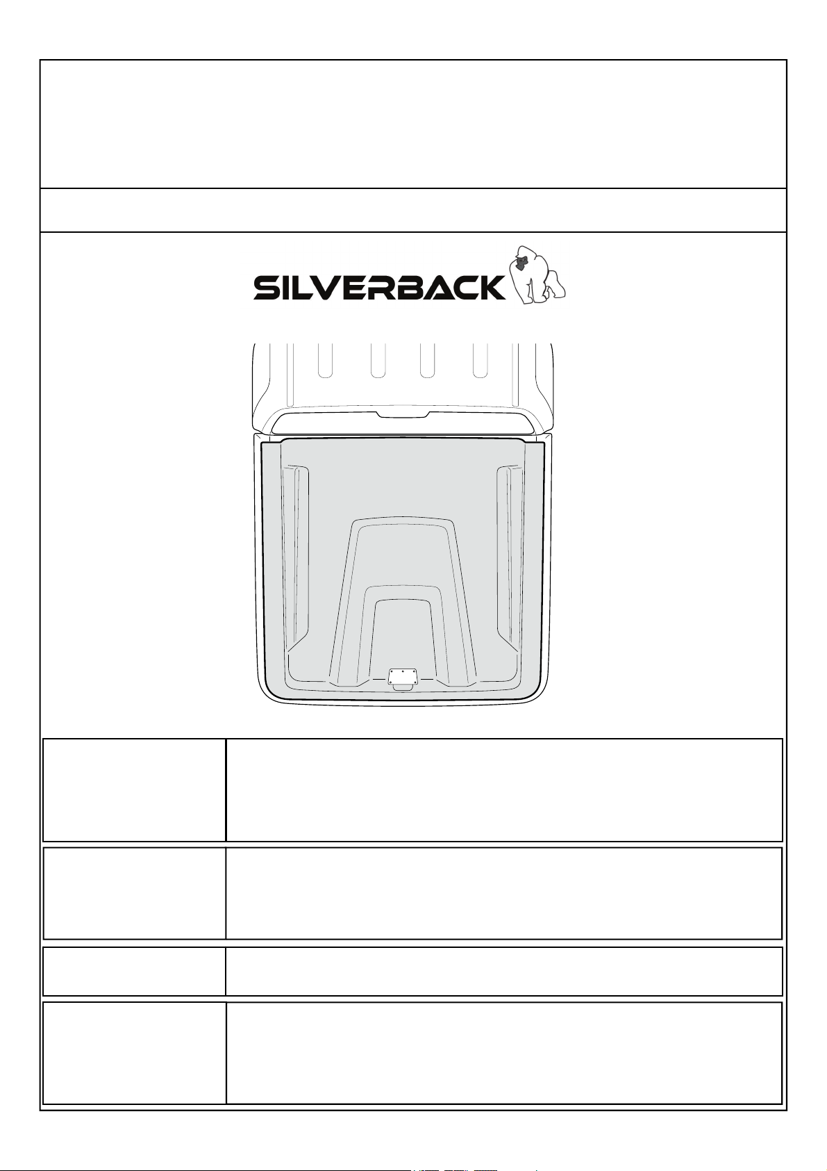
Fitting Instructions Part Number
B100 SILVERBACK MAZDA
BT50 Dual Cab 2011+
Check contents of kit before commencing fitment and report any discrepancies
IMPORTANT
Care Instructions
Maintenance
Tools Required
*Image example shown only
• Do not stand/sit or rest heavy objects on Tonneau Cover
• Humans or animals are not to be under the closed Tonneau at any given time
• Securely lock tonneau Cover before operating vehicle
• Tonneau Cover is not dust or water tight
• Do not carry open volatile chemicals with Tonneau Cover installed
• If contact with volatile chemicals occur, clean Tonneau with mild detergent and water solution
• Read Instructions fully before commencing installation.
• Clean Tonneau Cover with a mild detergent and water solution
• Do not use abrasive cleaners or solvents
• Refer to manufactures instructions applicable to power drill.
• Protect Tub floor against scratches during installation process.
If lubrication of the locks or hinges is required use only Graphite Powder. DO NOT use any other
lubricants or oils.
• Pen / Marker • Die Grinder & multi tool • Soapy water solution
• Centre Punch • Masking Tape • Allen Key set (Metric)
• Drill & Drill bits • Scissors & Knife
• Phillips head screwdriver • Ruler
• Caulking Gun • Spanner & Socket
• Silicon - Non Acetic • Tape measure
iSSUE 1: 23/05/19
Page 1 of 9
Page 2
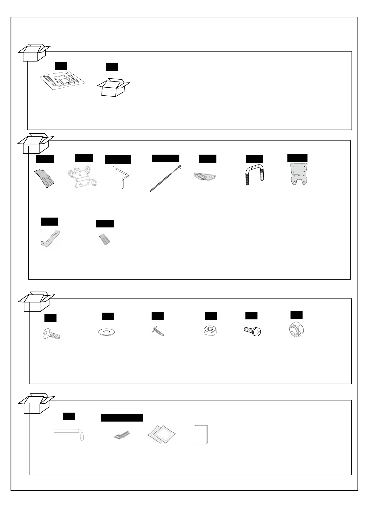
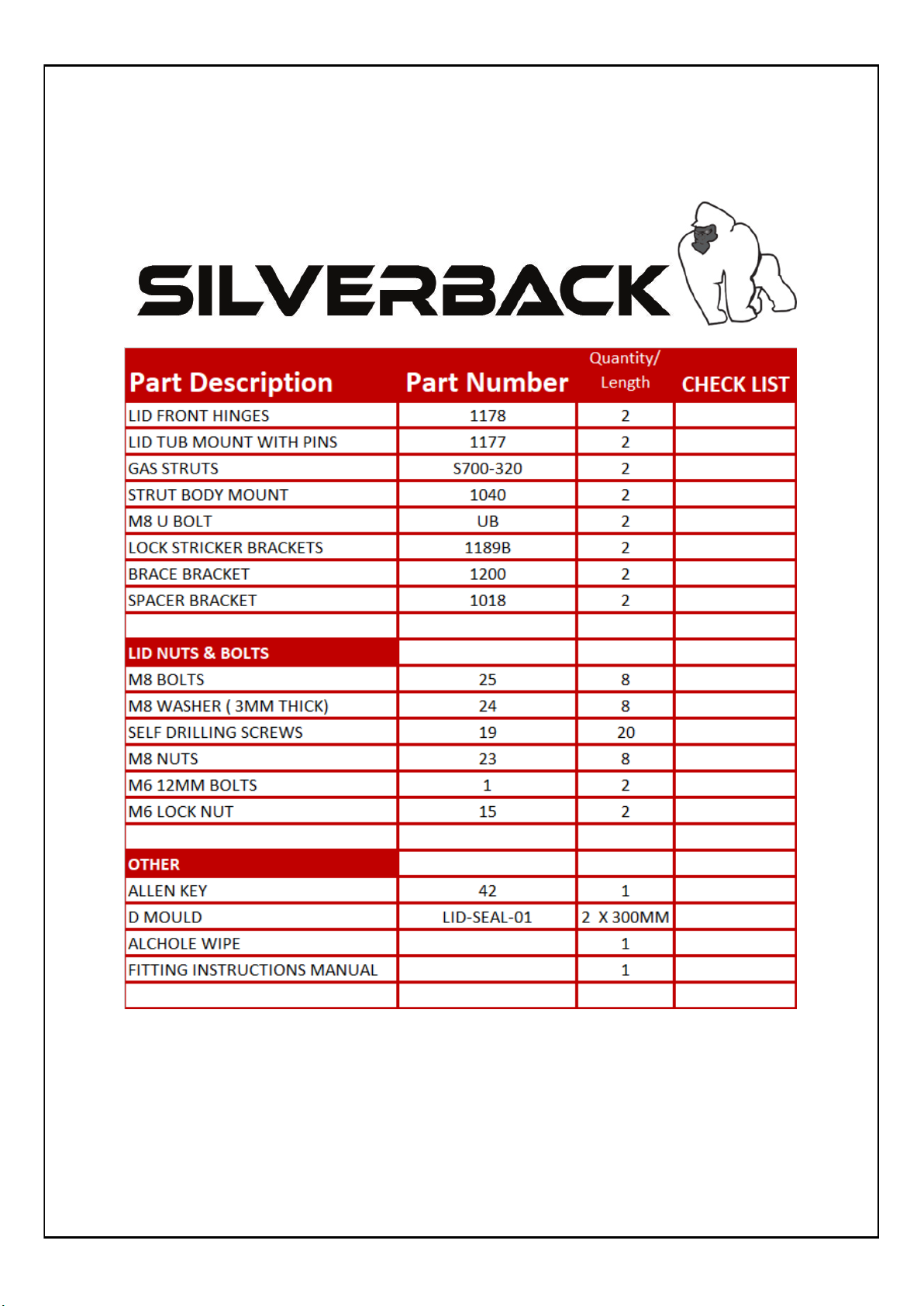
PARTS IN MAIN CARTON
PARTS CHECK SHEET
p100
Tonneau Cover
Qty - 1
PARTS IN FITTING KIT
1178
Lid HInge
Qty - 2
1200
1177
Hinge Bracket
Qty - 2
5
Fitting Kit
Qty - 1
1177P
Hinge Pin
Qty - 2
1018
S700-320
Gas Strut
Qty - 2
1040
Strut body mount
Qty - 2
UB
Striker U-Bolt
Qty - 2
1189B
Striker
Bracket
Qty - 2
Brace bracket
Qty - 2
LID NUTS AND BOLTS
25
M8x25 ALAN
Head Bolt
Qty - 8
OTHER
42
Support bracket
Qty - 2
24
M8 3mm thick
Flat Washer
Qty - 8
LID-SEAL-01
19
Self drilling
screws Qty - 20
Hex Nut
Qty - 8
Fitting
Instructions
23
M8
1
M6 12MM Bolt
Qty - 2
15
M6 Lock Nut
Qty - 2
Alan key
Qty - 1
D MOULD
Qty - 1
Alcohol wipe
Qty - 1
Fitting
Instruction
Qty - 1
Page 2 of 9
Page 3
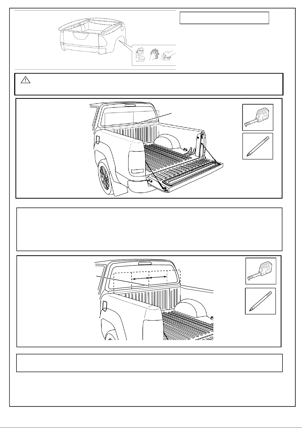
Thoroughly clean installation areas.
Important: Instructions are for Utes with an UNDER-RAIL tubliner. If you have an OVER-RAIL
tubliner you must trim the top off.
Find centre and
mark position.
Hinge mounts:
Align the hinge mounts along the front of the tray, ensuring the hinges are properly positioned from centre of tub
560 mm to centre of hinge mount either side along the inside of the front of the tub. Attach the hinges using selfdrilling screws (supplied) through holes pre-drilled into the hinges. Apply clear or black silicone to any gaps and
between the hinges and the vehicle to prevent water entry.
Measure distance
from centre on both
sides and mark.
Measure and mark the positions as indicated above from the centre of the bed for placement of the bottom hinges.
WARNING: RECHECK DIMENSIONS
TO ENSURE CORRECT MEASUREMENT
560 mm
560 mm
Page 3 of 9
Page 4
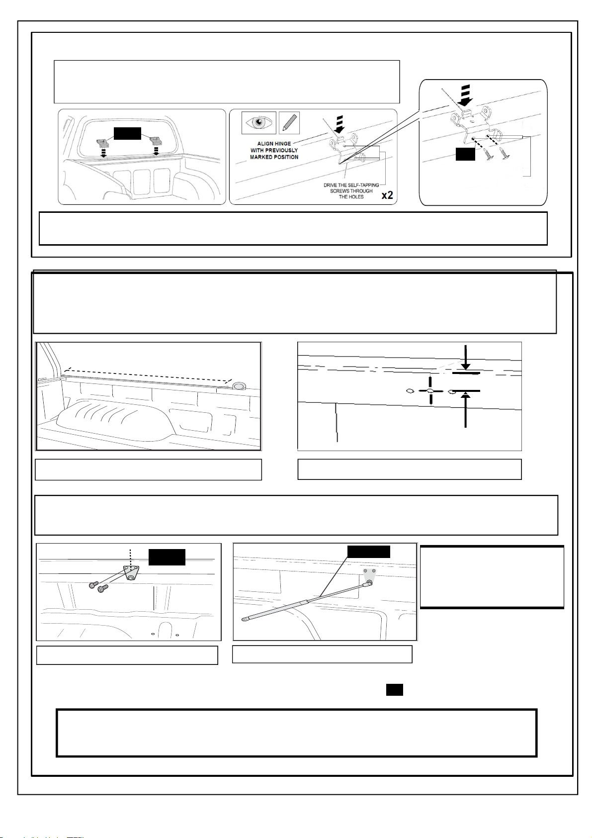
Hinge Mounts
Align hinge with previously marked position
1177
NOTE
19
Drill the bottom two holes first
and fasten using self-tapping
screws until tight. Drill and drive
the self tapping screw to
hole now.
16
the top
Using a 3.5MM drill bit, drill through the holes
hinge and clean any
hinge into the tub.
swarf,
apply Cold Galvanizing compound to the holes drilled
in the
top and
the base of the hinge plate into the tub. Remove
. Using the self-tapping s
Gas Struts:
Measure from the front rail inside of the tub, measure along the top edge of tray 760 mm
(windscreen end) then down 20mm and mark the position of the screws for the gas strut bracket.
Position the gas strut bracket accordingly, mark two mounting holes and centre. Refer to Fig. 1
and Fig. 2
760mm
20 mm
Fig.1 - Gas strut bracket location
Fig.2 - Gas strut bracket location
crews fasten the
Using a 2 mm diameter drill bit set to 5 mm drill stop. Drill two pilot holes. Attach small gas strut bracket using self
drilling screws provided. Repeat process on other side of tray. Refer to Fig. 2 and Fig.3
1040
Fig.3 - Gas strut bracket fitment
S700-320
Fig.4 - Gas strut orientation
19
Attach small shaft end of gas
strut onto gas strut brackets,
by clicking them in place. Refer
to Fig.4 with regard to gas strut
orientation.
Important:
DO NOT over tighten screws. Recommended tightening torque is 1- 3 Nm
Page 4 of 9
Page 5
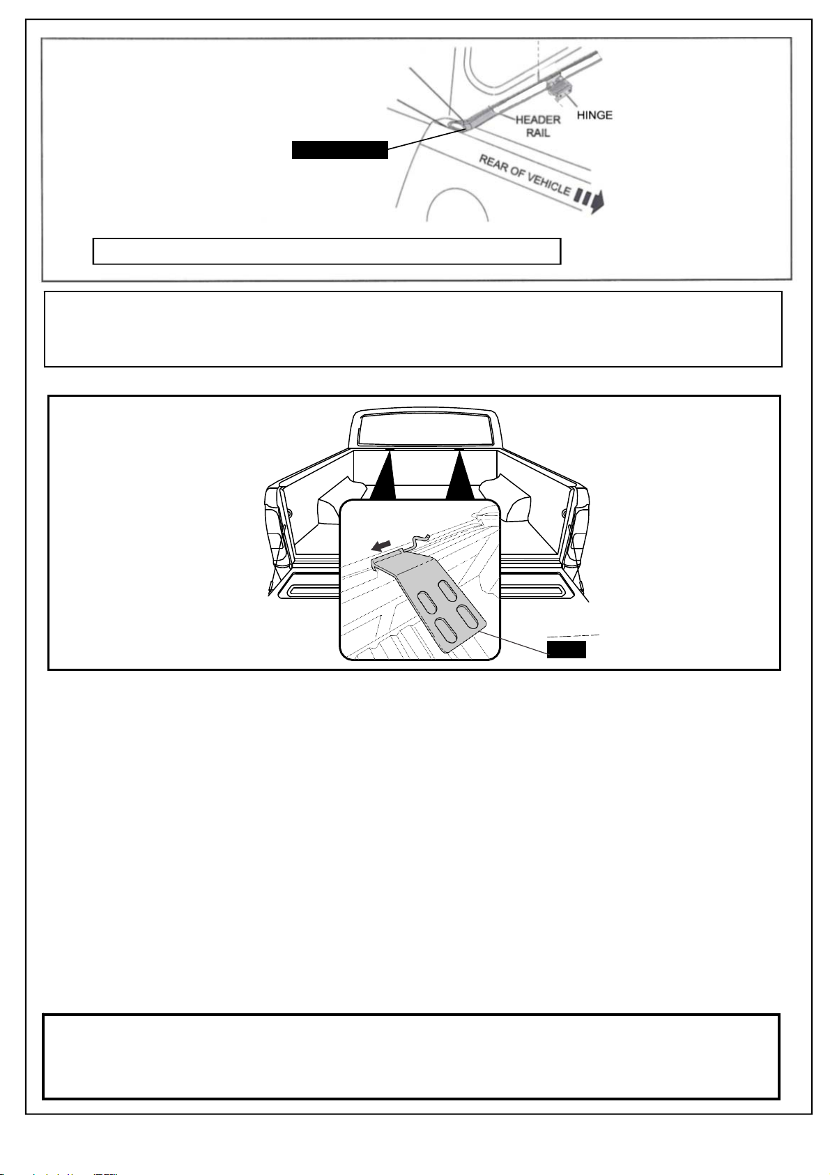
NOTE: SEALING LIP
MUST FACE TAILGATE
START EXTRUSION AT
EDGE OF SIDERAIL
Extrusion to finish
LID-SEAL-01
before hinge
You may cut off the desired excess at the end of your installation
Clean header rail (where extrusion will sit) with alcohol wipes provided and wipe away the residue with a dry clean
cloth. Place the extrusion tape seal along the top of the header rail with the sealing lip facing towards the tailgate.
Start the extrusion at the edge of the side rail. IMPORTANT: Position extrusion as close to the header rail rear
radius. Rub down firmly to ensure maximum adhesion.
Attach lid hinges to tub hinges by
aligning and pushing the pin
through.
Click pin down into hinge locking
tab
1178
Important:
Ensure tongues are fully inserted into the hinge slots with hinge pin securely in place.
Page 5 of 9
Page 6
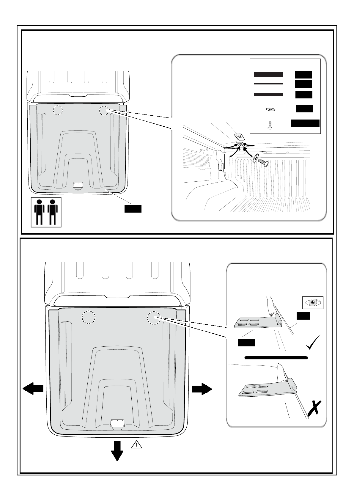
Place lid on tub. From inside follow the assumbly of hardware provided
100
Bolts are to be fitted
loosly to allow for
adjustment in the next
step.
ASSYMBLY ORDER
100
1018
1178
24
M8 BOLT
Adjust Lid so it is even on both sides and pull the lid back all the way so the front of the hinge bottoms out to
the inside front lip of the lid.
Note: Image showing lid in
upside down position
100
Inner
front lip of
ute lid
1178
Note: Pull lid back all the way so the front of the
hinge bottoms out ot the inside fron of the lid.
With the lid in adjusted position, crawl into the tub and tighten all 8 bolts to 3nm torque
Page 6 of 9
Page 7
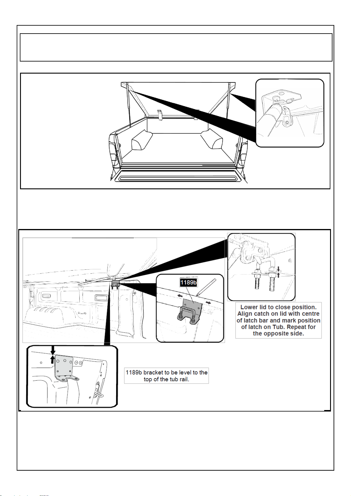
With the Hard Tonneau Cover opened, attach the cylinder end of each gas strut onto the mounting brackets
attached
to the Hard Tonneau Cover by clicking into place
Attach the gas struts between
the lid and the mounting brackets.
Page 7 of 9
Page 8
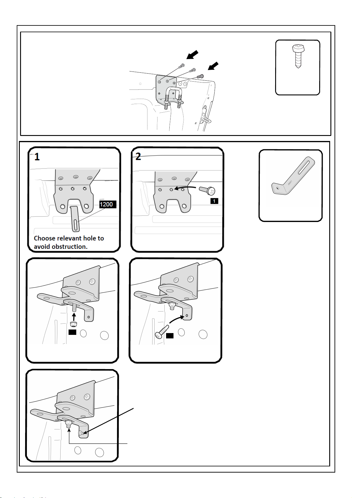
Fasten latch bracket
in place with self-tapping
screws.
Repeat for the opposite
side.
Part No: 19
Self Tapping
Screws
Part No: 1200
Brace Bracket
3
5
15
Tighten loosely
4
19
Align brace bracket against
tub inner wall.
1) Screw in using self drilling screw
2) Tighten fully
Page 8 of 9
Page 9
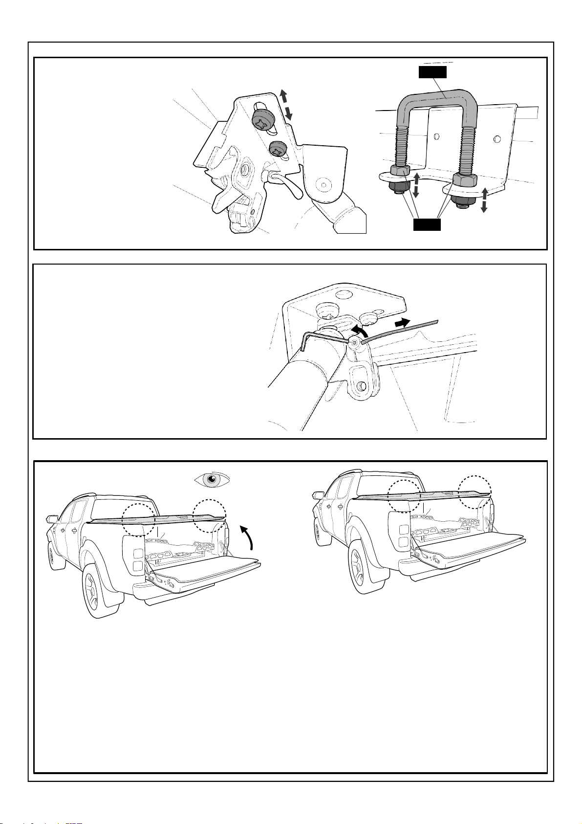
Loosen 2 screws and slide
catch to align correctly with
latch bar. Tighten screws to
secure in place.
Adjust nuts on latch bar to
alter height of bar to suit.
Repeat for the opposite
side.
Use an Allen key to loosen the hex key
screw on the catch and tension cable
so it is tight but doesn’t move the catch
at all, then re-tighten the hex key screw.
UB
23
With the lid in closed position, lift the tailgate .
The tailgate must close gently against the
silverback lid's seal.
If you find the tailgate is hard to close, put the
tailgate down and adjust the U bolt up until
the desired closing of tailgate is achieved.
NOTE: the seal must touch and compress
gently to achieve sealing.
Page 9 of 9
Page 10
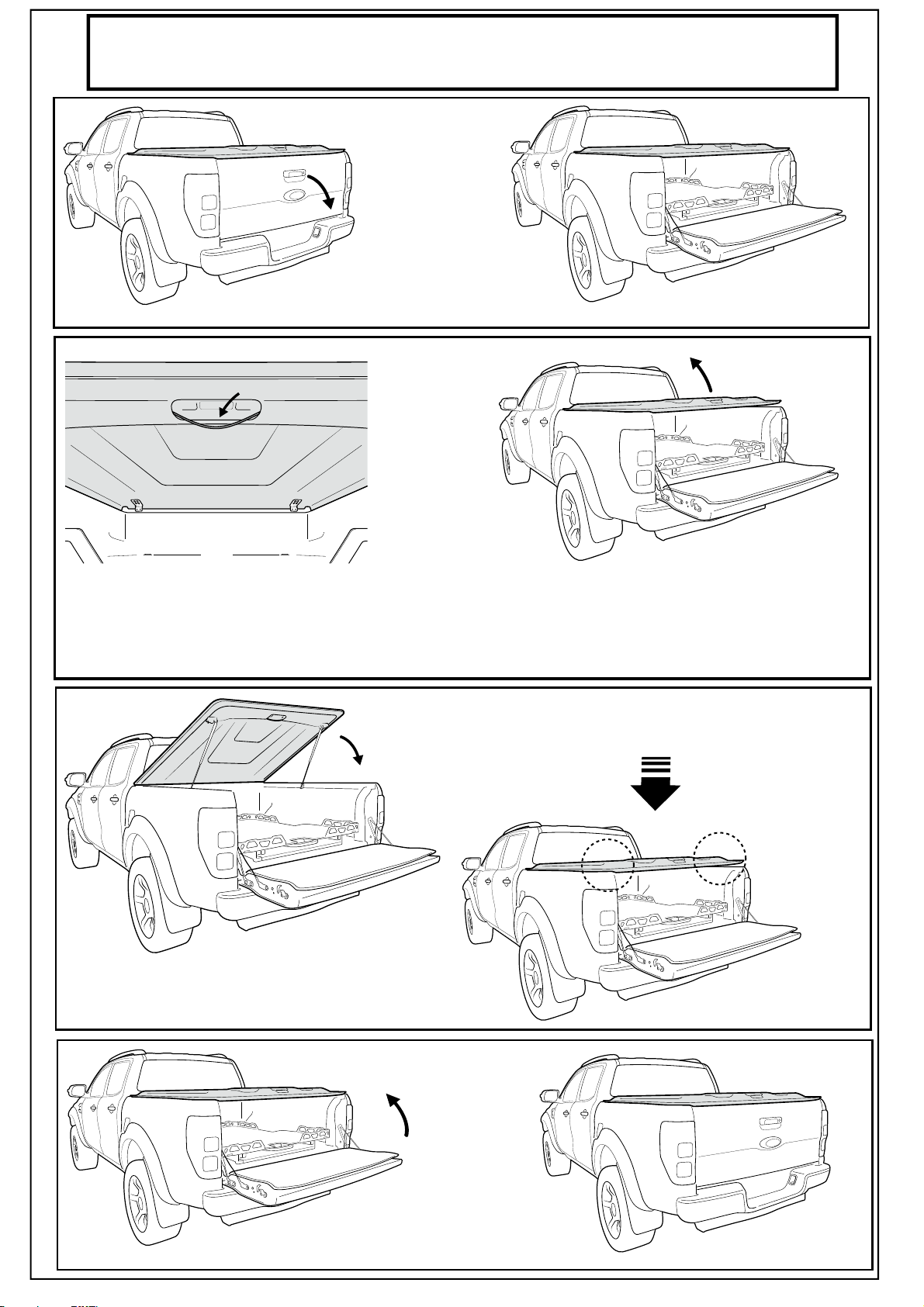
HOW TO OPERATE YOUR SILVERBACK LID
Open the tailgate
Now gently pull on the yellow release
cable, so the rotery latch releases.
Close the lid.
Aid the lid up, the gas springs will
take over and it will lift it all the way.
Push each corner of the lid down
so the rotaory latch is enagaged.
Close the tailgate
Page 11
Paint care instructions:
Your new painted Hard Tonneau Cover has been covered with a plastic film to protect the paint from damage. It will
require cleaning and possibly light polishing after the protective film has been removed. Use polish as per new paint
on a new vehicle. Wash Hard Tonneau Cover using water and normal carwash detergent and polish with an automotive polish.
NOTE: Please ensure Lid is kept locked at all times when not being used, for both safety and longevity.
Page 12
B100 SILVERBACK MAZDA
BT50 Dual Cab 2011+
 Loading...