

Page 1
MODEL NO.
B5402W
B5402F
SB60
BASKETBALL SYSTEM
O W N E R ' S M A N U A L
1. Read this manual carefully before starting assembly. Read each step completely before beginning
each step.
2. Some smaller parts may be shipped inside larger parts. Check inside all parts and cartons
before assembling or ordering parts.
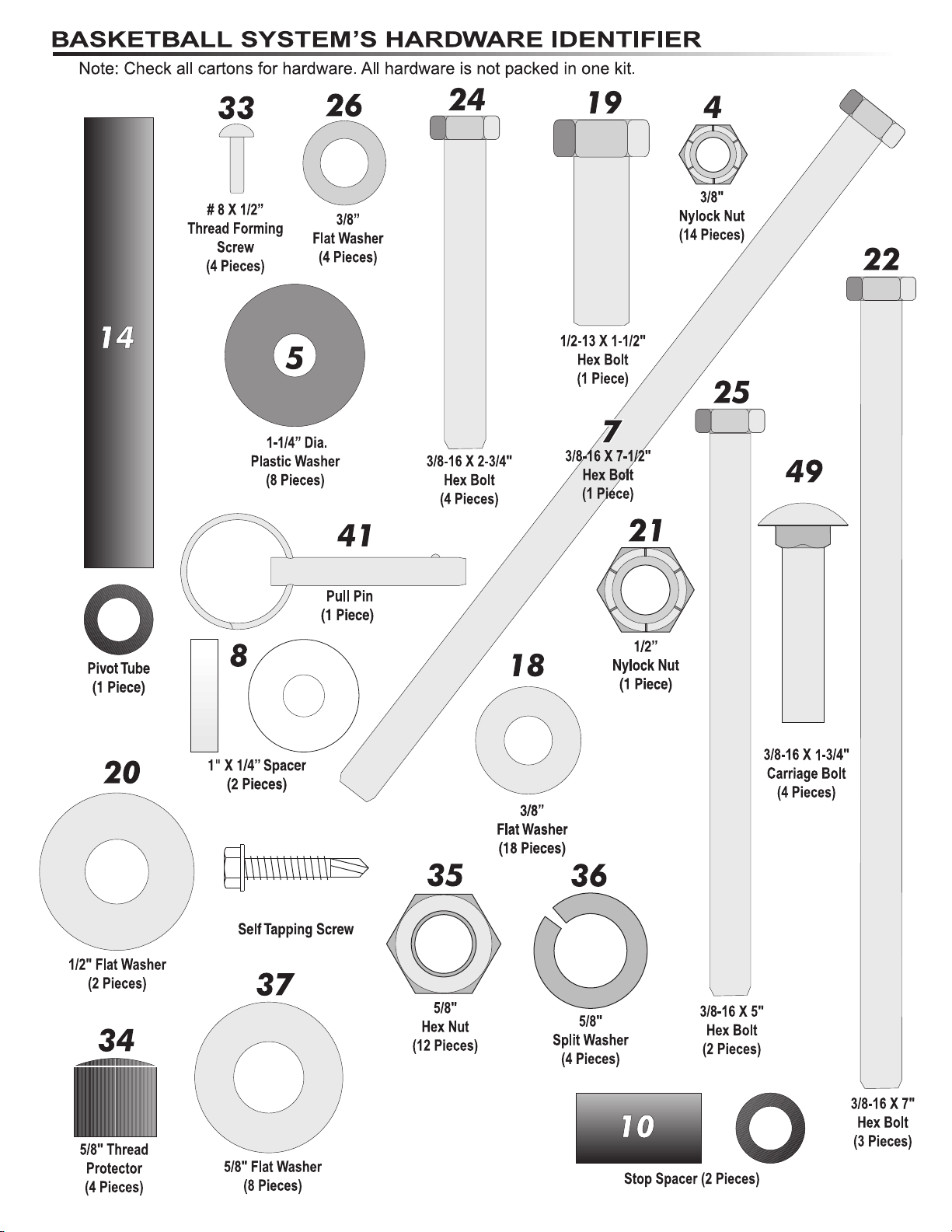
3. To make assembly of your basketball system easier, use the Hardware Identifier on page 3
to identify and sort all fasteners. Check all cartons for kits. All hardware is not located
in one kit.
4. Do not tighten hardware until instructed to do so. If hardware is tightened too soon, mounting holes
may not align and parts may not easily fit together. Leave locknuts slightly loose until you are instructed to
tighten them.
Save this instruction in the event that the manufacturer has to be contacted for replacement
5.
parts.
Please Do Not Return This Product To The Store!
Contact Escalade®Sports customer service department at:
Phone: 1-888-USA-GOAL T
Fax: 1-866-873-3536 T
E-mail: [email protected]
Mailing Address (correspondence only):
Escalade Sports
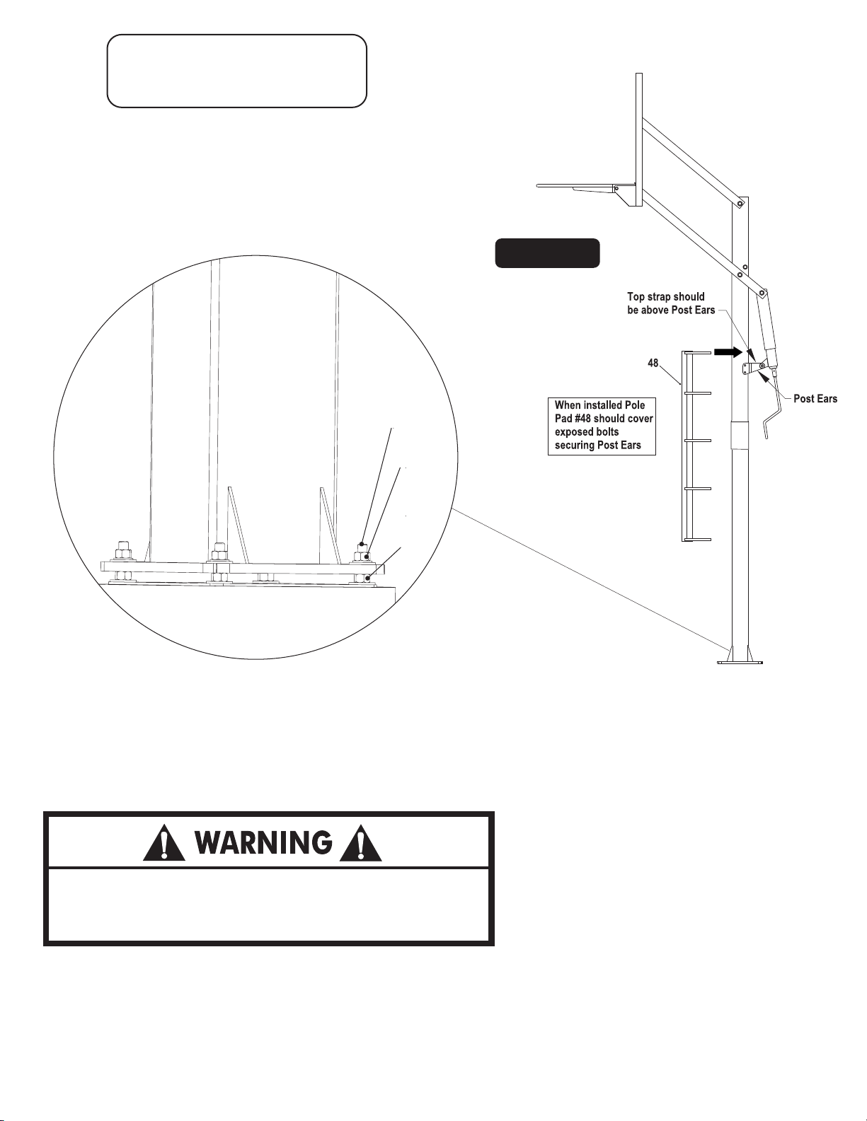
PO Box 889
Evansville, IN 47706
Please visit our World Wide Web site at: www.escaladesports.com
ON-LINE TROUBLE SHOOTING TECHNICAL ASSISTANCE
ON-LINE PARTS REQUESTS FREQUENTLY ASKED QUESTIONS
®
ADDITIONAL ESCALADE
SPORTS PRODUCT INFORMATION
oll Free!
oll Free!
Escalade®Sports products may be manufactured and/or licensed under the following patents:
6419596, 6179733, 5919102,5071120, 4798381, 4424968, D326128, 7244046
Additional patents may be pending. One or more of thelisted patents and/or pending patents may cover specific product.
2L-7198-00
©
2009 Escalade Sports
®
Page 2
SAFETY INSTRUCTIONS
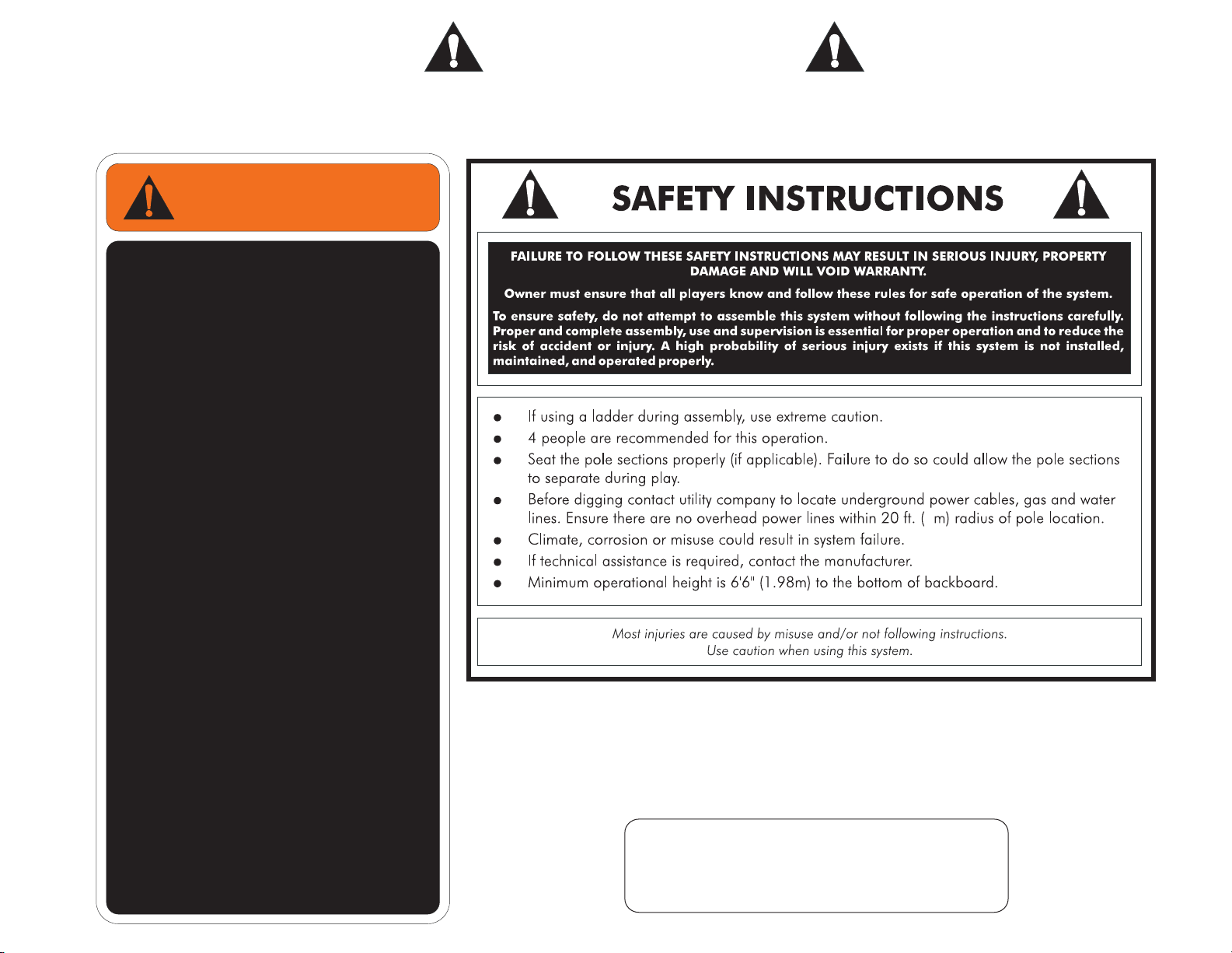
FAILURE TO FOLLOW THESE WARNINGS MAY RESULT IN SERIOUS INJURY AND/OR PROPERTY
Owner must ensure that all players know and follow these rules for safe operation of the system.
Owner must ensure that all players know and follow these rules for safe operation of the system.
WARNING
FAILURE TO FOLLOW THESE WARNINGS MAY
RESULT IN SERIOUS INJURYAND/OR PROPERTY
DAMAGE.
Owner must ensure that all players know and
follow these rulesfor safe operation ofthe system.
Do not dunkon this unit
Do not hangfrom any part ofthe unit, including
the backboard, rim,support braces, or net.
Do not slide,climb, or play onpole.
Keep organic material away from pole base.
Grass, litter,etc. could cause corrosionand /or
deterioration.
Check pole system for signs of corrosion
(rust, pitting, chipping). Remove rust and/or
loose paint completely and repaint with
exterior enamel paint. If rust has penetrated
through the steel anywhere, replace pole
immediately.
Check system before each use for proper
ballast, loose hardware, excessive wear, and
signs of corrosionand repair before using.
During play, use extreme caution to keep
players face away from the backboard, rim,
and net. Serious injury could occur if
teeth/face come in contact with backboard,
rim, or net.
Wear a mouth guard when playing to avoid
dental injuries.
When adjusting height, keep hands and
fingers away frommoving parts.
During play, do not wear jewelry (rings,
watches, necklaces, etc.). Objects may
entangle in net.
Do not allowchildren to adjust system.
Check system beforeeach use for instability.
Never play ondamaged equipment.
4L-8109-00
7
WARNING!
Failure to observe this warning
may cause property damage
and/or serious injury.
This product is NOT designed to support a player hanging from any
component of this basketball system.
Rim height adjustments should be made under parental supervision.
Wear a mouth guard when playing to avoid dental injuries.
During play, do not wear jewelry (rings, watches, necklaces, etc).
Objects may entangle in net.
DAMAGE.
(Affixed to backboard)
Page 3
77
#10 X 1 1/8”
(6 Pieces)
3
Page 4
INSTALLATION TIMELINE
1. Prior to anchor system and goal assembly, call utility services for location of underground utility lines before you dig.
2. Vertical main post assembly is a two part process.
PART 1
Day 1. Complete Anchor System Installation Instructions.
(Below)
Day 2-4. Allow concrete to cure.
ANCHOR SYSTEM INSTALLATION INSTRUCTIONS (Day 1)
Before digging hole for anchor system, check for
buried power, gas, water, and telecommunication
lines! Failure to do so could result in serious or fatal
injury! Contact your local utility company if unsure.
Items needed for Anchor Installation (not included)
9 - 80 lb. bags of concrete
1 - post hole digger (optional)
1 - 15/16” open end wrench
1 - 15/16” socket and ratchet (optional)
1 - concrete form (see note after step 2)
Note: For best results with less vibration, anchor system
should be independent of court. If pouring concrete for
both at same time, add an expansion joint in between.
Note: When digging hole, if you hit rock
and cannot dig through contact a contractor.
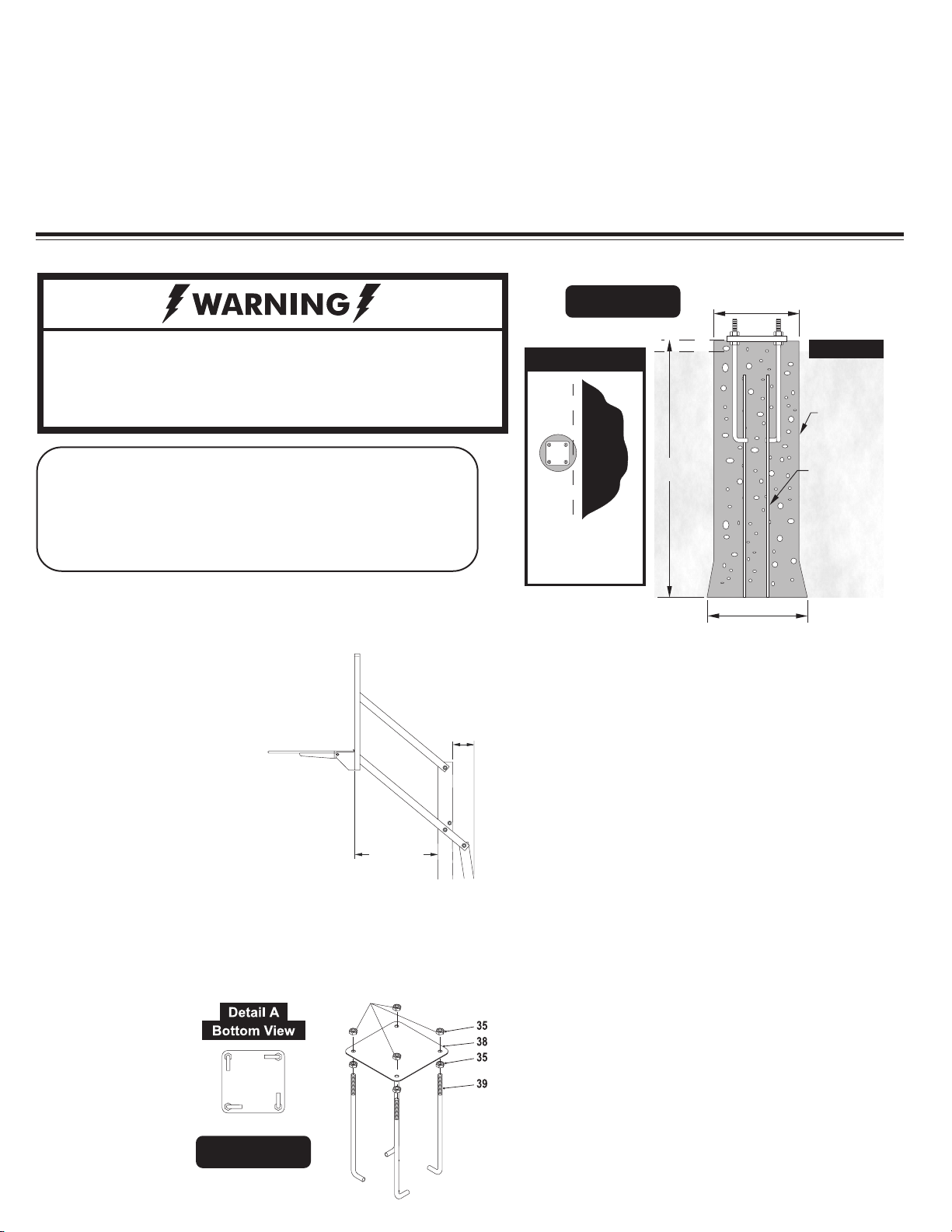
1. Determine the location of the anchor
system. The proper location is as close to
the court without making contact, as
shown in Figure 1. This,
however, is a general rule.
If you need to locate the
anchor system in a location other than
this, use the following dimensions as a
guide.
Overhang when adjusted to 10 ft. = 27”
1 - wheel barrow
1 - garden hose
1 - level
1 - tape measure
18 INCH
MINIMUM
REAR
CLEARANCE
REQUIRED
OVERHANG
PART 2
Day 5. Complete Silverback® assembly instructions. (Requires
four adults)
Figure 1
Court Level
Top View
Court
36”
Anchor Plate must be
square to your court so
the backboard will
line up with court.
16” Diameter
Court
Concrete
Rebar #40
20” Diameter
Note: It is recommended that you use some sort of
concrete form for the top 4" of the concrete. Cardboard
forms can be purchased at some hardware and home
stores or a wooden form can be constructed out of 2 x
4's.
3. Mix and pour concrete into hole. Follow instructions on
concrete bag. Stop about 18" below court level.
Note: Minimum of 18” rear clearance is required behind pole.
2. Assemble anchor system as follows: Thread nut (#35) to bottom
of threads on anchor bolt (#39) insert threads of anchor bolt
(#39) through hole on anchor plate (#38) and secure with
nut (#35). Repeat this step for the
remaining anchor
bolts. See Figure
THESE NUTS
USED FOR
LEVELING
2. Note: Each leg
of anchor bolts
should face the
anchor bolt to the
right. See Detail A.
Figure 2
4. Insert four reinforcement bars (#40) into concrete 8" apart
creating a square in center on hole.
5. Finish pouring concrete up to court level.
6. Push anchor system into concrete and agitate to work out
voids in concrete. Immediately use a level to level and square
anchor plate to playing surface. Clean off any concrete that
may be on exposed threads.
Note: The bottom four nuts will be forever embedded
in concrete. The top four nuts remain on bolts and
are used for leveling. (See Step 14 on page 7).
Let concrete stand for a MINIMUM of 72 hours.
Page 5
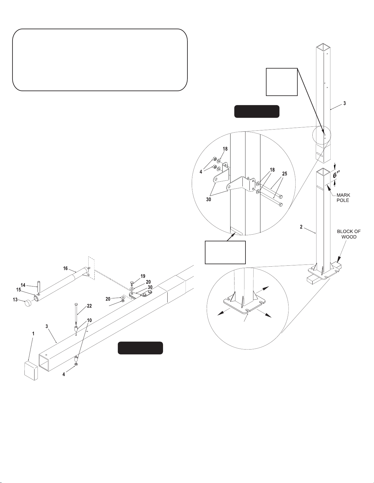
SILVERBACK ASSEMBLY INSTRUCTIONS (Day 5)
TOOLS REQUIRED FOR THE FOLLOWING STEPS
1 - 15/16" Open end Wrench
1 - 15/16” Socket and Ratchet (optional)
1 - 9/16” Deep Well Socket & Ratchet
1 - 9/16” Open end Wrench
1 - 3/4” Socket & Ratchet
1 - 3/4” Open end Wrench
1 - Pair of Safety Glasses
IMPORTANT! Nylon washers (#5) adequately space
painted parts at all pivot points. Neglecting the use of
these washers will result in rusted parts.
NOTE: All board arms are made of rectangular tubing.
Tightening hardware too tight may damage tubing
and make adjustment of system difficult.
1 - Phillips Screwdriver
1 - Level
1 - Tape Measure
1 - Rubber Mallet
1 - Set of Padded
Saw Horses
Be sure that
the holes are
toward the
back of the
pole.
Figure 3
1.
Before putting any of the poles tubes together, mark bottom
pole (#2) 6 inches from the top end. Be sure to match up
both “Back Side” stickers on the back of the poles
and that the holes on top pole are toward the back.
See Figure 3.
2.
Align the upper pole (#3) with the bottom pole (#2) as
shown in Figure 3 and slide them together. Stand poles up
on a block of wood, lift poles up and hit on a block of
wood until the bottom of the upper pole reaches the 6”
mark on the bottom pole. Hit poles a minimum of 7 times.
This is a friction-locking joint and requires no hardware.
IMPORTANT! DO NOT hit poles with hammer or
sledge hammer to slide poles together.
21
CBA
K SIDE
Match up both
“Back Side”
stickers on the
back of the poles.
BACK
NOTCHES IN BASE
PLATE MUST BE ON
SIDE AS SHOWN
FRONT
SIDE
BACK SIDE
BAC SIDE
K
Figure 4
3. Attach Post Ears (#30) to holes near the bottom of Top
Post (#3) using two hex bolts (#25) four washers (#18)
and two lock nuts (#4). See Figure 3.
Slide Actuator Sleeve (#15) over Actuator (#16) and place
4.
Actuator Cap (#13) on top. Slide Pivot Tube (#14) through hole
near top of Actuator & Actuator Sleeve until equal amounts
stick out through both sides of Actuator. See Figure 4.
Note: If necessary, use a rubber mallet to tap in
Pivot Tube (#14)
5. Lay Pole Assembly on its side on two padded saw horses. Slide
tab on Actuator (#16) between Post Ears (#30) and secure
using one bolt (#19), two washers (#20) and one lock nut
(#4). See Figure 4. Tighten bolts tight.
Place Pole Cap (#1) onto top of Top P
6.
ole (#3). Note: Pole
Cap may be pre-installed by the factory.
7. Secure two stop spacers (#10) to pole, as shown in Figure
4, using one hex bolt (#22) and one lock nut (#4).
5
Page 6
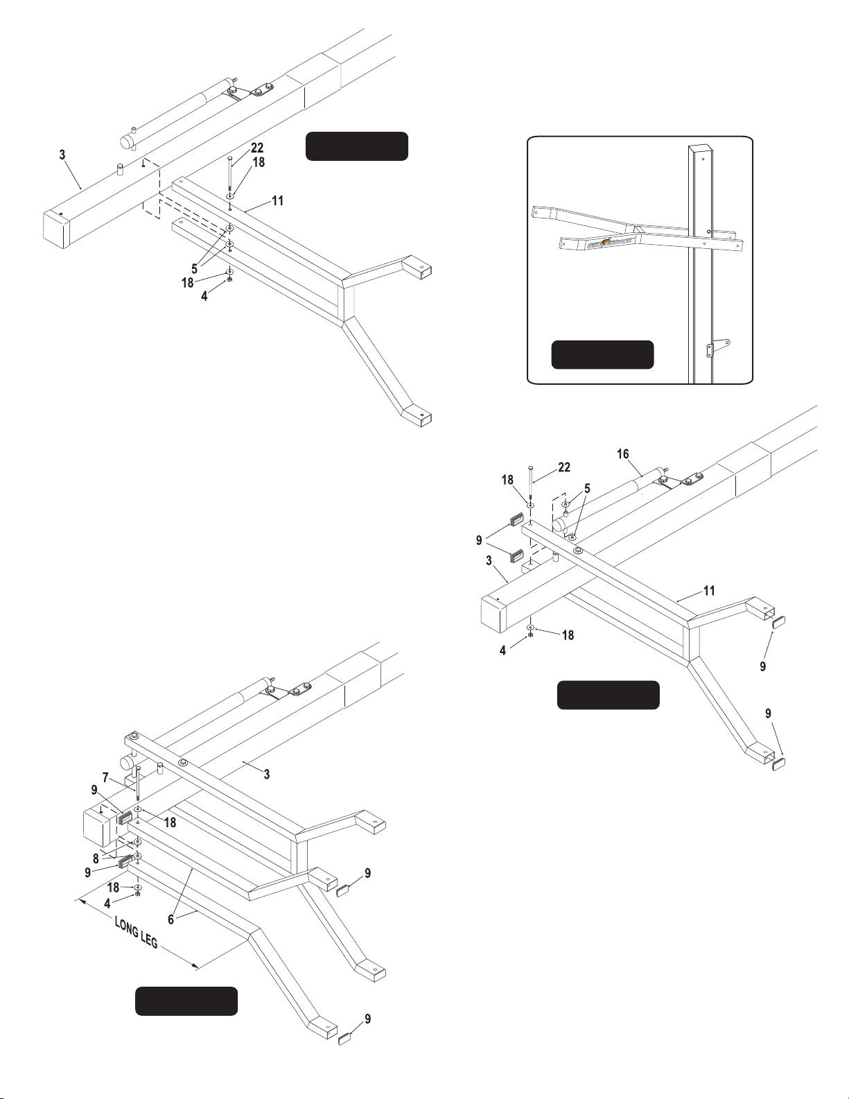
Figure 5
9. Secure Actuator (#16) to Lower Arms (#11) using one bolt
(#22), two flat washers (#18), two plastic washers (#5) and
one lock nut (#4). See Figure 6. Tighten both bolts (#22)
securing Lower Arm (#11).
Note: Tighten bolts snug but, do not over tighten. Board
Arms must pivot freely.
8. Attach lower arms (#11) to Top Pole (#3), as shown in
Figure 5, using a hex bolt (#22), two flat washers (#18),
two plastic washers (#5) and lock nut (#4).
Note: make sure lettering is right side up. (See Side View).
DO NOT tighten bolt (#22) at this time. (See Figure 5.)
SIDE VIEW
10. Insert four Tube Plugs (#9) into open ends of Lower Arms
(#11). It may be necessary to use a rubber mallet to tap them
in. See Figure 6. Note: Tube plugs may be pre-installed
by the factory.
Figure 6
11. Attach long leg of Upper Arms (#6) to Top Pole (#3), as
shown in Figure 7, using a bolt (#7), two flat washers (#18),
two spacers (#8) and one lock nut (#4).
Note: Tighten bolts snug but, do not over tighten. Board
Arms must pivot freely.
12. Insert four Tube Plugs (#9) into open ends of Upper Arms
(#6). It may be necessary to use a rubber mallet to tap plug
in. See Figure 7. Note: Tube plugs may be pre-installed
by the factory.
Figure 7Figure 7
6
Page 7
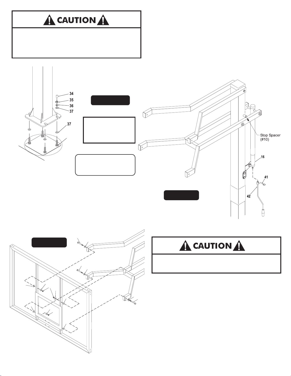
13. Locate hardware needed to mount pole to anchor bolts. You
will need, eight flat washers (#37), four lock washers (#36),
four hex nuts (#35) and four thread protectors (#34).
PLACING THE POST ON THE ANCHOR SYSTEM
REQUIRES AT LEAST FOUR CAPABLE ADULTS.
POLE WILL WANT TO LEAN WHILE ATTEMPTING TO
STAND IT UP ON ANCHOR BOLTS.
Figure 8
BE SURE CONCRETE
HAS BEEN ALLOWED
35
(Bottom Nut)
P
L
A
Y
I S
NG U
R
FA
C
E
TO CURE FOR AT
LEAST 3 DAYS
Note:
Bottom nuts #35 can
be used for leveling system.
See Step 14.
Note: Do not remove the nuts you installed in step 2 (pg. 4).
14.
Put a flat washer (#37) on each anchor bolt. Lift post onto
anchor system and secure with one flatwasher (#37), one
lock washer (#36) and one hex nut (#35) for each anchor
bolt. Tighten Fasteners finger tight, leave loose enough to
level pole. Place a level on pole and adjust bottom nuts #35
until pole is level. Tighten top four hex nuts #35 tight.
Place a thread protector (#34) on each anchor bolt.
15. Slide Actuator Crank (#42) onto shaft on the bottom of
Actuator (#16). Line up hole in shaft with hole in Actuator
Crank and insert Pin (#41) to secure. See Figure 9.
16. To aid in the assembly of the backboard, lower the backboard,
by turning the Actuator Crank, until the lower arm makes
contact with Stop Spacer (#10).
24
Figure 10
5
5
18
4
18
18
5
4
5
18
24
18
Figure 9
ATTACHING B A CKBO ARD TO BOARD A RMS
REQUIRES AT LEAST FOUR CAPABLE ADULTS.
17. With at least three capable people, raise the backboard assembly
up and have the fourth attach Lower Board Arms to lower mounting
18
24
tubes on backboard using two bolts (#24), two plastic washers
(#5), four washers (#18) and two lock nuts (#4). See Figure 10.
NOTE: DO NOT over tighten these bolts. This is a pivot point.
Snug is tight enough.
18. Attach Upper Board Arms to upper mounting tubes on backboard
using two bolts (#24), two plastic washers (#5), four washers
(#18) and two lock nuts (#4). See Figure 10.
NOTE: DO NOT over tighten these bolts. This is a pivot point.
Snug is tight enough.
7
Page 8
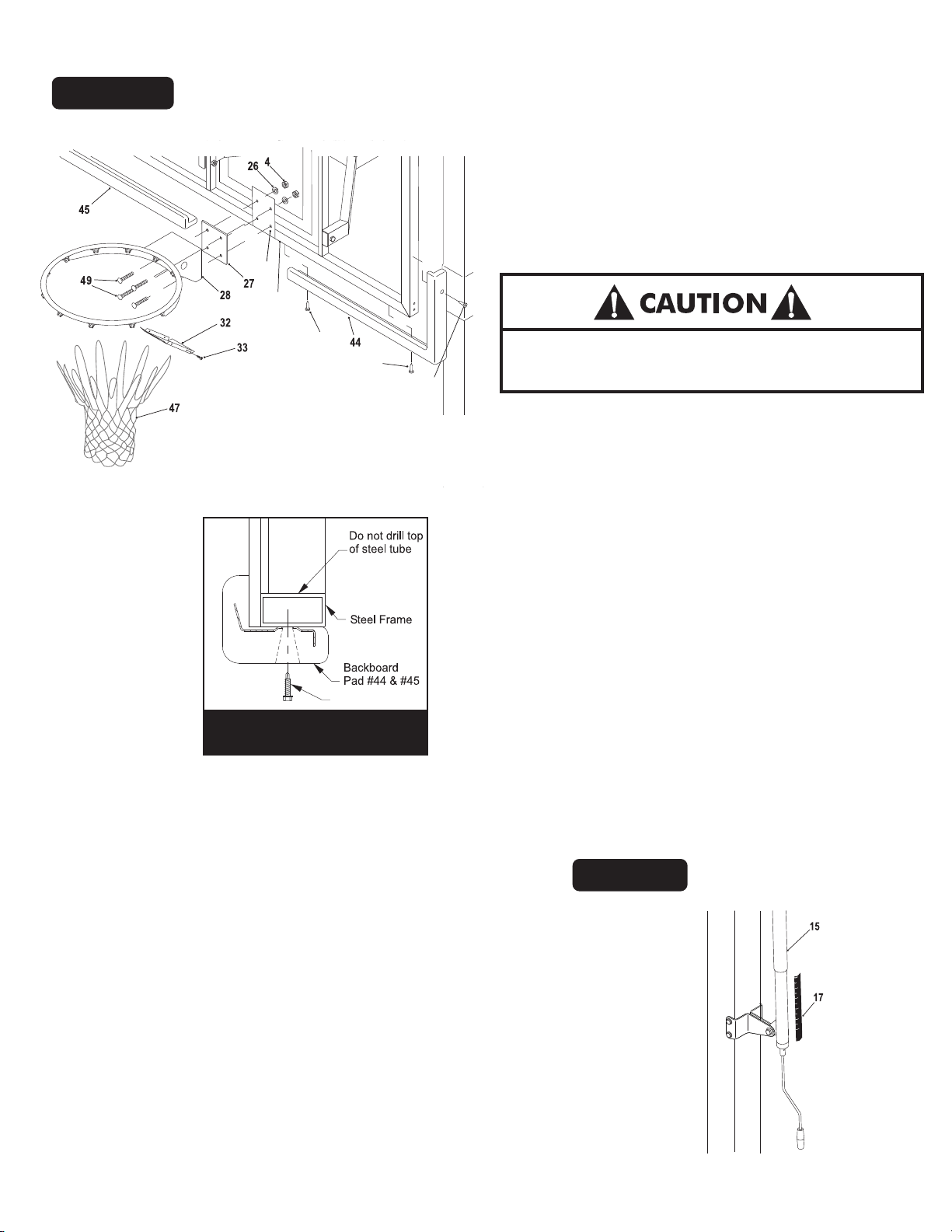
Figure 11
29
23
77
77
19. Remove protective backboard covering and mount Goal
Assembly (#28) and Rim Pad (#27) to Backboard, as shown
in Figure 11, using four bolts (#49), four washers (#26), and
four locknuts (#4). Tighten fasteners finger tight, leave them
loose enough to level rim.
20. Place a level across rim assembly and adjust rim until it is
level. Finish tightening the four nuts.
NEVER USE RIM WITH COVERPLATE REMOVED!
77
21. Attach Rim Cover Plate (#32) using four screws (#33). See
Figure 11.
22. Check all nuts and bolts and make sure everything is
tightened properly.DO NOT over tighten pivot points,
snug is tight enough.
Screw #77
Detail A
26. Adjust unit to 7-1/2 feet. Use a tape measure to measure from
the top of the rim to the playing surface. Stick Height Decal
(#17) to back of Actuator (#16) with the "7.5" mark aligned
with bottom of Actuator Sleeve (#15). See Figure 12.
23. Use the Backboard Pads (#44) and (#45) as a template and
mark the hole locations on the backboard frame. See Figure
11 and Detail A.
Note: Safety glasses required for Step 24.
24. Drill 9/64" pilot holes into steel backboard frame. See
Detail A. Do not drill through both sides of tube.
25. Secure Backboard P
ads (#37) and (#38), as shown, using
screws (#42). Note: Tighten screws tight but, do not over
tighten screws.
Note: Cordless drill recommended for screw installation.
Do not over tighten screws.
Figure 12
8
Page 9
Two adults are recommended for
this step, one to level and one to
adjust the bottom #35 nuts.
If further leveling is required loosen top #35 nuts but do
27.
not loosen past the top of #39 “J” Bolt.
REMOVE NUTS #35 Place a level on pole and adjust
bottom nuts #35 with a 15/16” open end wrench until
pole is level. Tighten top #35 hex nuts. See Detail B.
.
DO NOT
Figure 13
39
35
35
(Bottom)
Detail B
28. Secure Post Pad (#48) to front of pole by wrapping straps around
pole and sticking to velcro on opposite side of Pad. Top Post Pad
strap should be above Post Ears. See Figure 13.
Protruding bolts can cause serious injury. Never use this unit
without Pole Pad (#48) firmly in place and covering Post Ear
bolts. If Pole Pad is damaged, replace before using this unit.
9
Page 10

LIMITED 7 YEAR WARRANTY
This consumer warranty extends to the original consumer purchase of any Escalade
®
Sports Product (hereinafter referred to as
the “Product”).
WARRANTY COVERAGE: Escalade
®
Sports warrants to the original Consumer Purchaser that any Product of its manufacture is
free from defects in material and workmanship. THIS WARRANTY IS VOID IF THE PRODUCT HAS BEEN DAMAGED BY ACCIDENT,
UNREASONABLE USE, NEGLIGENCE, IMPROPER SERVICE, FAILURE TO FOLLOW INSTRUCTIONS PROVIDED WITH THE PRODUCT
OR OTHER CAUSES NOT ARISING OUT OF DEFECTS IN MATERIAL OR WORKMANSHIP.
Subject to proper installation and normal Residential use, Escalade Sports warrants, subject to the limitations below, to the original retail
®
purchaser all structural components of the Silverback® System to be free of defects in material and workmanship for a period of
Seven (7) years from the original purchase.
Merchandise must be shipped prepaid with a copy of proof of purchase to Escalade
if the basketball system needs to be repaired or replaced. Any labor costs, travel expenses and any other changes involved in the
removal, installation or replacement of the defective/repaired parts from/to your Silverback
Shipping charges for replaced or warranted merchandise sent back to the customer from Escalade
®
Sports factory for examination to determine
®
System will be the purchaser’s responsibility.
®
Sports factory must be prepaid
by the customer in advance. If not, the replacement shipment will be sent out collect.
Escalade
®
Sports reserves the right to examine photographs or physical evidence of merchandise claimed to be defective, and to
recover said merchandise, prior to authorization of warranty claims. A “Returned Goods Authorization” number may be required,
please call for details prior to the return of any photographs or merchandise.
This limited 7 year warranty is expressly in lieu of all warranties, expressed or implied, including warranties of merchantability or fitness for
use. Escalade
®
Sports does not assume or authorize any person or representative to assume for us, any other liability in connection with the
sale of our products.
The remedy of repair or replacement stated above is Escalade
other damages or expenses which may incur, including but not limited to incidental or consequential damages. Escalade
assumes no other obligations or liability on the part of the purchaser, and Escalade
®
Sports exclusive remedy. Escalade® Sports will not be liable for any
®
Sports neither assumes nor authorizes any other
®
Sports
person to assume for it any other liability in connection with the goods sold.
This warranty shall not apply in any manner to parts or accessories not manufactured by Escalade
®
Sports.
NOT COVERED BY THIS WARRANTY
•
Merchandise not intended to be in places of public assembly, such as, but not limited to, schools, parks, public or private recreational
facilities.
• Any merchandise subjected to Non-residential abuse, negligence, improper installation, vandalism, acts of God, alteration of product,
or any other events beyond the control of Escalade Sports.
• Paint or rusted parts. If rust should appear, remove loose paint, sand lightly, primer and paint with exterior flat matte finish
enamel paint.
• HANGING ON RIM WILL VOID THE WARRANTY: Rims are not warranted for any defects other than workmanship. Torn back plates,
damaged springs, bent rings, damaged eyebolts, and torn or distorted rim supports result from hanging on the rim and are not
warranted.
• Shipping charges both ways. Note: Any merchandise shipped to Escalade
• Dealer service charges, labor charges and travel expenses associated with replacement of repair of warranty item.
WARRANTY DISCLAIMERS: ANY IMPLIED WARRANTIES ARISING OUT OF THIS SALE, INCLUDING BUT NOT LIMITED TO THE
IMPLIED WARRANTIES OF MERCHANTABILITY AND FITNESS FOR A PARTICULAR PURPOSE, ARE LIMITED IN DURATION.
ESCALADE
®
SPORTS SHALL NOT BE LIABLE FOR LOSS OF USE OF THE PRODUCT OR OTHER CONSEQUENTIAL OR INCIDENTAL
COSTS. EXPENSES OR DAMAGES INCURRED BY THE CONSUMER OF ANY OTHER USE.
Some states do not allow the exclusion or limitation of implied warranties or consequential or incidental damages, so the above limitations
or exclusions may not apply to you.
LEGAL REMEDIES: This warranty gives you specific legal rights, and you may also have other rights which may vary from state to state.
®
®
Sports collect will be refused.
WARRANTY GUIDELINES IS REQUIRED FOR ALL WARRANTY CLAIMS
1. Proof of Purchase (original retail purchaser) is required for all warranty claims.
2. Call or write Escalade
Phone: 1-888-USA-GOAL / Warranty Dept.
Or Write Escalade
Or E-mail us at: [email protected]
®
Sports to receive a Return Authorization # and determine specific needs.
®
Sports at: Escalade® Sports - P.O. Box 889, Evansville, IN 47706 - Attn: Warranty Dept.
10
Page 11
SILVERBACK CARE INFORMATION
- BACKBOARD -
Items needed to clean backboard:
- 100% cotton soft cloth, (only)
- Glass Cleaner
Clean backboard using a 100% Cotton soft cloth and glass cleaner. Clean glass as you would household windows. Strong cleansers will damage
backboard and void warranty.
– RIM –
HANGING ON THE RIM WILL VOID YOUR WARRANTY. Rims are not warranted for any defects other than workmanship. Torn back plates,
damaged springs, bent rings, damaged eye bolts, and torn or distorted rim supports result from hanging on the rim and are not warranted.
The goal should not be cranked under 7-1/2' or over 10'. Adjustments of the goal should be done under adult supervision.
When attempting slam dunk activity you should always wear a mouth guard to avoid dental injury.
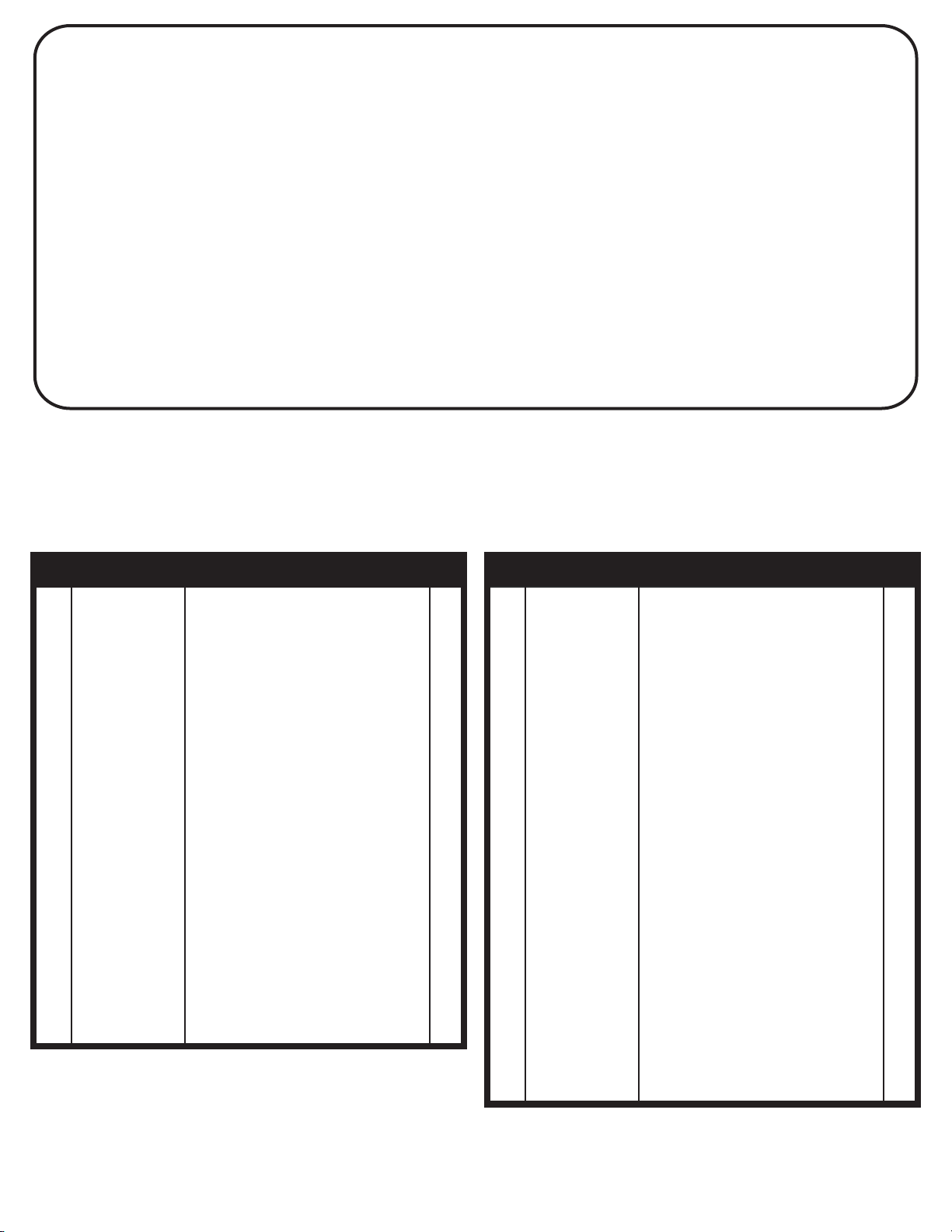
B5402 REPLACEMENT PARTS LIST
Key# Part # Description Qty. Key# Part # Description Qty.
1 3M-6850-00 4" Square Tube Plug 1
2 1A-6335-02 Bottom Post 1
3 8S-6644-02 Top Post 1
4 901-28 3/8-16 Nylon Locknut 14
5 3M-6883-00 1-1/4" OD Plastic Washer 8
6 8S-6630-01 Upper Board Arm 2
7 1B-6483-10 3/8-16 X 7.5" Hex Bolt-Grade 5 1
8 3M-6269-00 1/4" Spacer 2
9 3M-6548-00 1 X 2 Tube Plug 8
10 8S -6657-00 Stop Spacer 2
11 1A-6331-01 Lower Board Arm 1
12 Not Used
13 3M-6467-00 Actuator Cap 1
14 8S -6658-00 Pivot Tube 1
15 3M-6542-00 Actuator Sleeve 1
16 4A-6605-00 Actuator 1
17 4L-7501-00 Height Decal 1
18 701-50 3/8 STD Washer 18
19 1B-6486-10 1/2-13 X 1-1/2" Hex Bolt 1
20 2B-6093-00 1/2 Flat Washer 2
21 2B-6095-00 1/2-13 Nylon Locknut 1
22 1B-6484-10 3/8-16 X 7" Hex Bolt-Grade 5 3
23 6A-7404-01 Backboard Assembly-60x33” Glass 1
24 1B-6195-00 3/8-16 X 2.75" Hex Bolt 4
25 1B-6485-10 3/8-16 X 5" Hex Bolt 2
26 2B-6114-00 3/8 Flat Washer 4
27 3M-6473-00 3X4 Rim Pad 1
28 6A-6374-00 Goal Assembly 1
29 3M-6835-00 Goal Spacer Plate (Pre-Installed)
1
30 2S-6795-01 Post Ear 2
31 Not Used
32 2S -6427-00 Rim Cover Plate 1
33 1B-6788-00 #8 x 1/2 Thread Forming Scr. 4
34 3M-6469-00 5/8 Thread Protector 4
35 2B-6097-00 5/8-11 Hex Nut 12
36 2B-6099-00 5/8 Split Lockwasher 4
37 2B-6098-01 5/8 SAE FLAT WSHR ZNC 8
38 2S -6453-00 Anchor T. emplate 1
39 2B-6112-00 5/8-11 X 14 "J" Bolt 4
40 1S -6167-00 #3 X 30" Rebar 4
41 7B-6255-00 Pull Pin 1
42 4A-6606-00 Actuator Handle 1
43 2L-7198-00 This Manual 1
44 3M-6580-01 48" Board Pad Right 1
45 3M-6581-01 48" Board Pad Left 1
46 Not Used
47 3F-6010-00 Net 1
48 3M-6564-01 Post Pad 1
49 1B-6782-00 3/8-16 x 1 3/4" Carriage Bolt 4
50 Not Used
77 1B-6821-00 Self Tapping Screw-#10 x 1 1/8" 6
11
2L-7198-00
Page 12
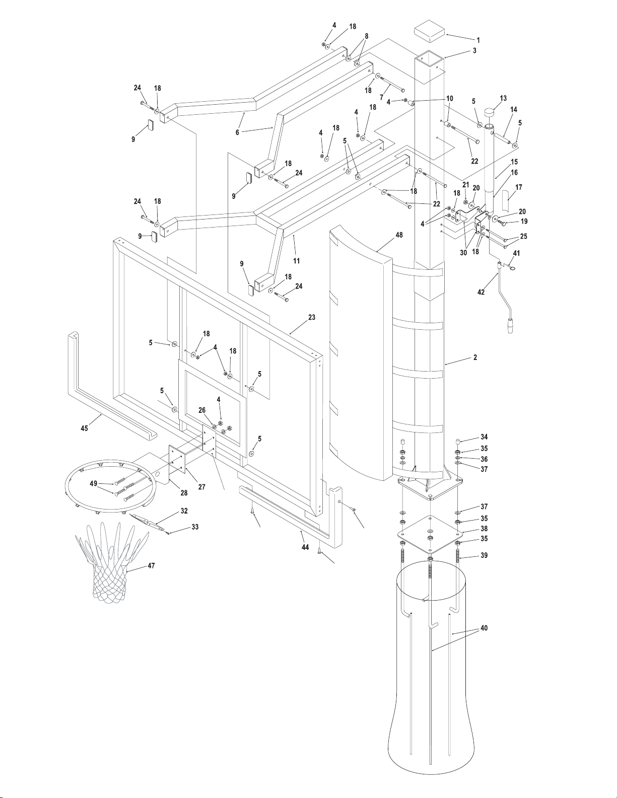
29
(Pre-Installed)
77
12
77
77
2L-7198-00
 Loading...