

Page 1

Table of Contents
2. Safety Information ................................................ 5
2.1 Conventions Used ...................................... 5
2.2 Important Safety Instructions ...................... 5
3. Using This Manual ............................................... 7
4. Introduction .......................................................... 8
4.1 About OBDII/EOBD .................................... 8
4.2 About the Code Reader ............................ 11
5. OBDII/EOBD Diagnosis ..................................... 16
5.1 Reading DTCs .......................................... 17
5.2 Clearing DTCs .......................................... 18
5.3 Viewing Datastream ................................. 20
5.4 Viewing Freeze Data ................................ 20
5.5 Reading I/M Readiness Status Data ........ 21
5.6 Reading Vehicle Information .................... 24
5.7 Exiting Test ............................................... 25
6. Updating the Code Reader ................................ 26
7. Troubleshooting ................................................. 28
VS70 OBDII/EOBD Code Reader User’s Guide_English Version_V1.10
1
Page 2
g
p
y
p
2. Safety Information
For your safety, and to prevent damage to the equipment and
vehicles, read this manual thoroughly before operating your
VS70 code reader. The safety messages presented below and
throughout this user’s manual are reminders to the operator to
exercise extreme care when using this device. Always refer to
and follow safety messages and test procedures provided by the
manufacturer of the vehicle or equipment being tested. Read,
understand and follow all safety messages and instructions in
this manual.
2.1 Conventions Used
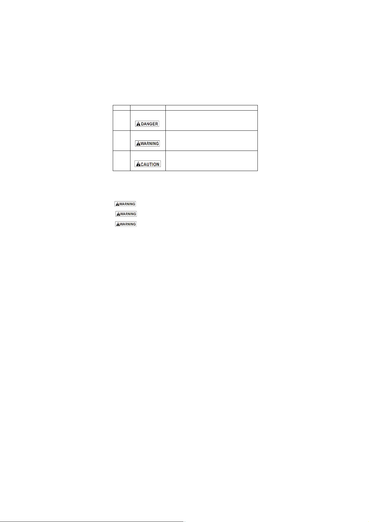
We provide safety messages to help prevent personal injury and
equipment damage. Below are signal words we used to indicate
the hazard level in a condition.
No. Si
1
2
3
nal Word Hazard Level
Indicates an imminently hazardous
Indicates a potentially hazardous
Indicates a potentially hazardous
situation which, if not avoided, will
result in death or serious injury to the
o
erator or to bystanders.
situation which, if not avoided, could
result in death or serious injury to the
operator or to b
situation which, if not avoided, may
result in moderate or minor injury to the
o
erator or to bystanders.
standers.
2.2 Important Safety Instructions
And always use your code reader as described in the user’s
manual, and follow all safety messages.
interfere with driving controls.
specified in this user’s manual.
your eyes from propelled objects as well as hot or caustic
VS70 OBDII/EOBD Code Reader User’s Guide_English Version_V1.10
Do not route the test cable in a manner that would
Do not exceed voltage limits between inputs
Always wear ANSI approved goggles to protect
5
Page 3

liquids.
acid, refrigerant and other debris produced by a malfunction
engine can cause serious injury or death. Do not use code
reader in areas where explosive vapor may collect, such as in
below-ground pits, confined areas, or areas that are less than 18
inches (45 cm) above the floor.
near the vehicle while testing and keep all sparks, heated items
and open flames away from the battery and fuel / fuel vapors as
they are highly flammable.
gasoline, chemical and electrical fires in work area.
speed when an engine is running and keep a safe distance from
these parts as well as other potentially moving objects to avoid
serious injury.
when an engine is running to avoid severe burns.
running. Put the transmission in park (for automatic transmission)
or neutral (for manual transmission). And never leave a running
engine unattended.
working on engine.
disconnecting the code reader.
Fuel, oil vapors, hot steam, hot toxic exhaust gases,
Do not smoke, strike a match, or cause a spark
Keep a dry chemical fire extinguisher suitable for
Always be aware of rotating parts that move at high
Do not touch engine components that get very hot
Block drive wheels before testing with engine
Do not wear jewelry or loose fitting clothing when
Make sure to turn off ignition before connecting or
VS70 OBDII/EOBD Code Reader User’s Guide_English Version_V1.10
6
Page 4

3. Using This Manual
We provide instructions for the usage of your code reader in this
manual.
Below is a list of conventions we used in the manual.
Safety Information
See
Safety Information
Bold Text
Bold emphasis is used in procedures to highlight selectable
items such as buttons and menu options.
Example:
Use the SCROLL key to select the desired measurement unit.
Bold-Italic Text
Bold-italic text is used in the procedures to highlight the menus
on the code reader screen.
Example:
Use the SCROLL key to select Language from
Setup
screen.
Symbols and Icons
√ Check Note
Additional information about the subject in the preceding
paragraph is introduced by a √ Check Note.
Example:
√ The code reader is set to display English menus by
default.
● Solid Spot
Operation tips and lists that apply to specific tool are introduced
by a solid spot ●.
Example:
System Setup
IMPORTANT
IMPORTANT indicates a situation which, if not avoided, may
result in damage to the test equipment or vehicle.
Example:
IMPORTANT Do not soak keypad as water might find its
way into the code reader.
VS70 OBDII/EOBD Code Reader User’s Guide_English Version_V1.10
allows you to:
● Select menu languages.
● Change measurement unit.
● Adjust display contrast.
on page 5-6.
System
7
Page 5

NOTE
NOTE provides helpful information such as additional
explanations, tips, and comments.
Example:
NOTE Not all data are supported by all vehicles.
Screens
Some help messages, information, and data displayed on the
code reader are also shown in graphical text boxes. The
screens presented are examples only and actual test screens
may vary for each vehicle being tested.
Example:
Arrow Icon
An arrow icon indicates a procedure.
Example:
To change menu language:
1. Use the SCROLL key to select Language from
Setup
2. Press the YES/NO key to confirm.
Diagnostic Menu
Read Codes
Erase Codes
Live Data
Freeze Data
System
screen.
4. Introduction
VS70 is developed by the most distinguished mind of the
industry. It is specially designed to read/clear codes, read live
data, retrieve freeze data and request vehicle information on
OBDII/EOBD compliant cars, SUVs, light-duty truck and
mini-vans sold worldwide since 1996.
4.1 About OBDII/EOBD
What is OBD?
The first generation of On-Board Diagnostics or OBD I was
VS70 OBDII/EOBD Code Reader User’s Guide_English Version_V1.10
8
Page 6
introduced in early 1980's to control engine functions and
diagnose engine problems by vehicle manufacturers. As the
OBDI lacked standardization of protocols and interface, it
allowed different interpretations among vehicle manufacturers.
OBDII, the second generation On-Board Diagnostics, improved
in both capability and standardization, is a system developed in
mid 1990’s by the Society Automotive Engineers (SAE) to
standardize automotive electronic diagnosis. EOBD is European
version of OBDII required in Europe since 2001.
The OBDII standard specifies:
● A generic diagnostic port (Data Link Connector) and
its pinout;
● The protocols and the messaging format;
● A standard list of vehicle parameters identifications;
● A standard list of diagnostic trouble codes (DTCs);
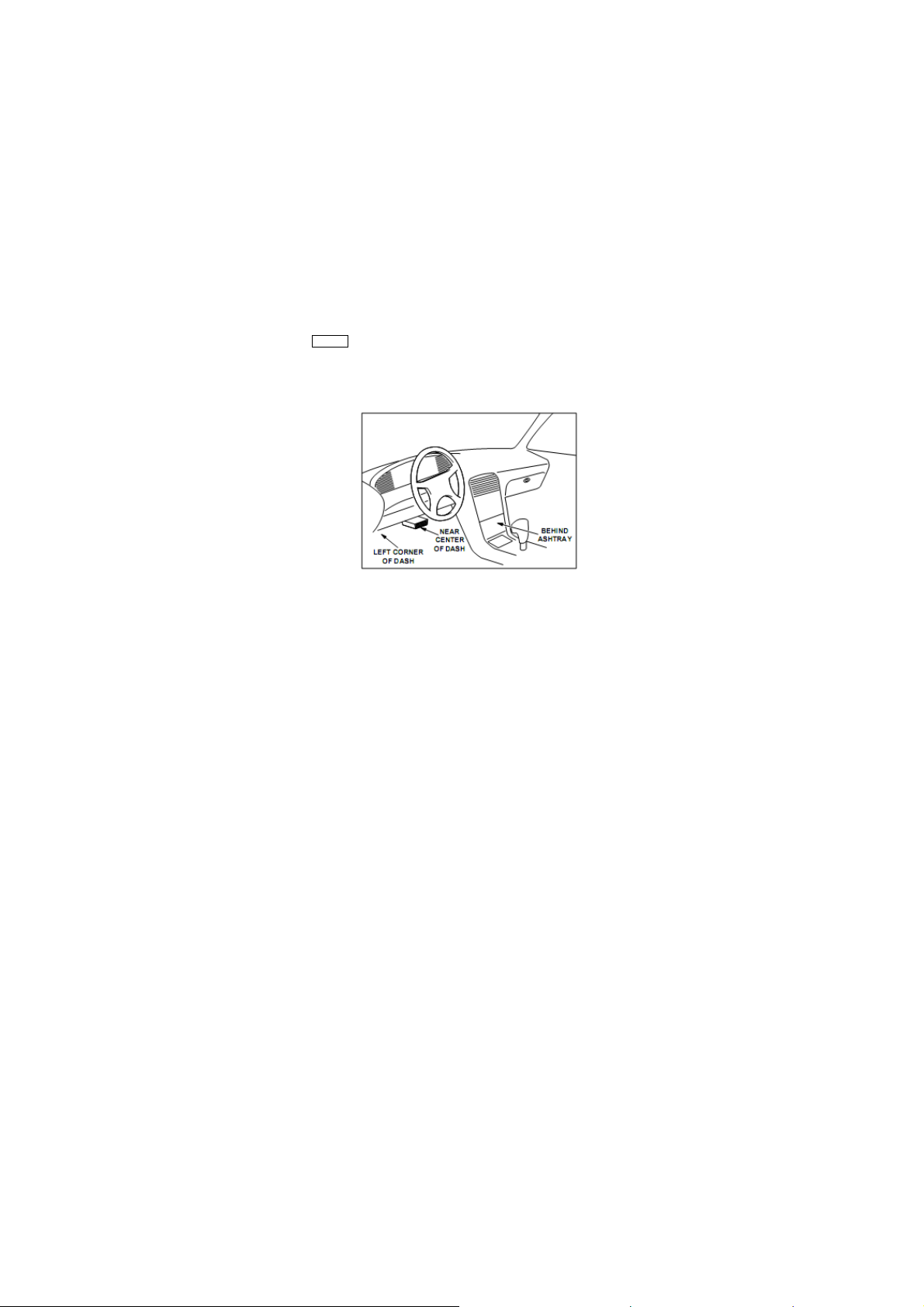
Data Link Connector
The Data Link Connector (DLC) is a standard 16-pin interface
located under the dashboard on the driver's side of the
passenger compartment. If the DLC is not located under the
dashboard as stated, a decal describing its location should be
attached to the dashboard in the area where the DLC should
have been located.
NOTE On some Asian and European vehicles the DLC is
located behind the “ashtray”, which must be removed to
access it, or on the far left corner of the dash. If the DLC
cannot be found, consult the vehicle’s service manual for
the location.
VS70 OBDII/EOBD Code Reader User’s Guide_English Version_V1.10
9
Page 7
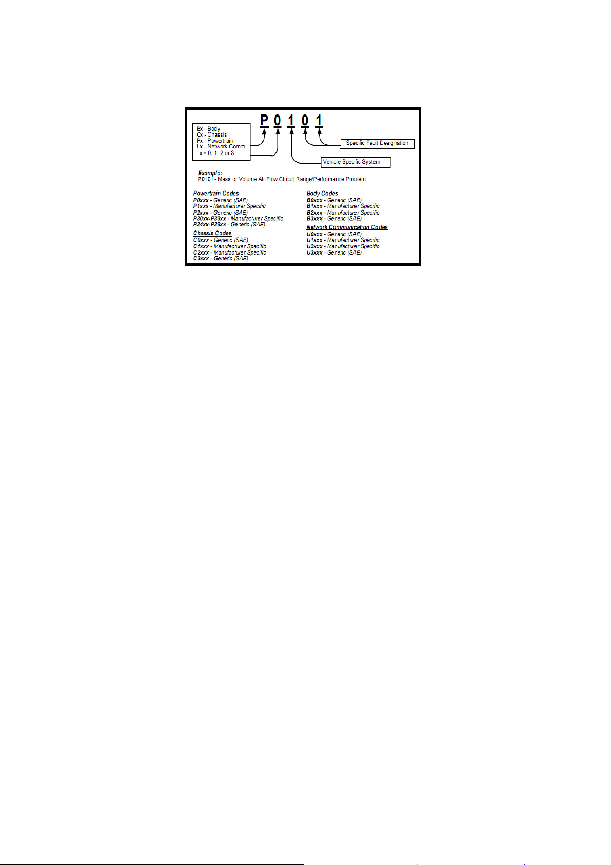
Diagnostic Trouble Codes (DTCs)
Diagnostic Trouble Codes (DTCs) are faults stored by vehicle
computers when problems that affect engine performance and
emissions are detected. DTCs are used to help identify the
cause of a trouble or troubles with a vehicle, and determine the
fault location(s).
DTCs consist of a five-digit alphanumeric code. Please see
below for the DTCs format and code types.
VS70 OBDII/EOBD Code Reader User’s Guide_English Version_V1.10
10
Page 8
4.2 About the Code Reader
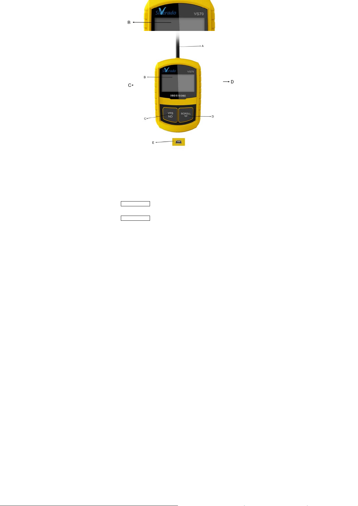
Code Reader Controls
A. OBD II Cable - provides communication for vehicle DLC.
B. LCD Display – shows menus, test results and operation tips.
C. YES/NO Key – confirms an action or returns to previous
screen or level.
D. SCROLL Key - moves selection up or down. Also, press it to
enter system setup menu from home screen.
E. USB Port – provides a USB connection for the PC or laptop.
F. Rear Decal – provides serial number of code reader.
IMPORTANT Do not use solvents such as alcohol to clean
keypad or display. Use a mild nonabrasive detergent and a
soft cotton cloth.
IMPORTANT Do not soak keypad as water might find its
way into the code reader.
VS70 OBDII/EOBD Code Reader User’s Guide_English Version_V1.10
11
Page 9

j
Accessories Included
No. Part Description
1 User’s Manual
2 USB Cable
Provides operation instructions for
the usage of code reader.
Provides USB communication for
updates of software and DTCs.
Specifications
No. Item Specification
1 Display
Working
2
Temperature
Storage
3
Temperature
4 Power 8-18 Volts powered by vehicle battery
Dimensions
5
(L*W*H)
6 Weight 300g
Backlit, 128 x 64 pixel display with
contrast ad
0 to 60℃ (32 to 140℉)
-20 to 70℃ (-4 to 158℉)
120*75*20mm (4.7*2.96*0.78in)
ustment.
Display Indicators
Below is a list indictors used to help navigate through menus.
No. Indicator Description
1 $ Indicates the control unit number.
2
Indicates more than one screen of
information is available.
Power
The code reader is powered up by vehicle battery.
√ Refer to Code Reader Does Not Power Up in section 7.2
on page 29 of Troubleshooting if there are problems.
VS70 OBDII/EOBD Code Reader User’s Guide_English Version_V1.10
12
Page 10

To power up the code reader:
1. Locate the diagnostic interface on vehicle.
2. Plug in the code reader’s OBDII connector to the DLC.
NOTE A plastic DLC cover may be found on some vehicles.
Remove the cover before plugging the OBD2 cable.
System Setup
System Setup
To do system setup:
1. Press the SCROLL key to enter
Changing Language
To change menu language:
1. Use the SCROLL key to pick Language from
2. Press the YES/NO key to confirm.
VS70 OBDII/EOBD Code Reader User’s Guide_English Version_V1.10
allows you to:
●
Select menu languages.
● Change measurement unit.
● Adjust display contrast.
√
System Setup
existing setups are made.
home screen.
settings remain until change to the
System Setup
System Setup
Language
Measurement Unit
Contrast
Exit
√
Follow on-screen instructions to program the code
reader to meet your specific needs.
√ The code reader is set to display English menus by
default.
Setup
screen.
13
from
System
Page 11
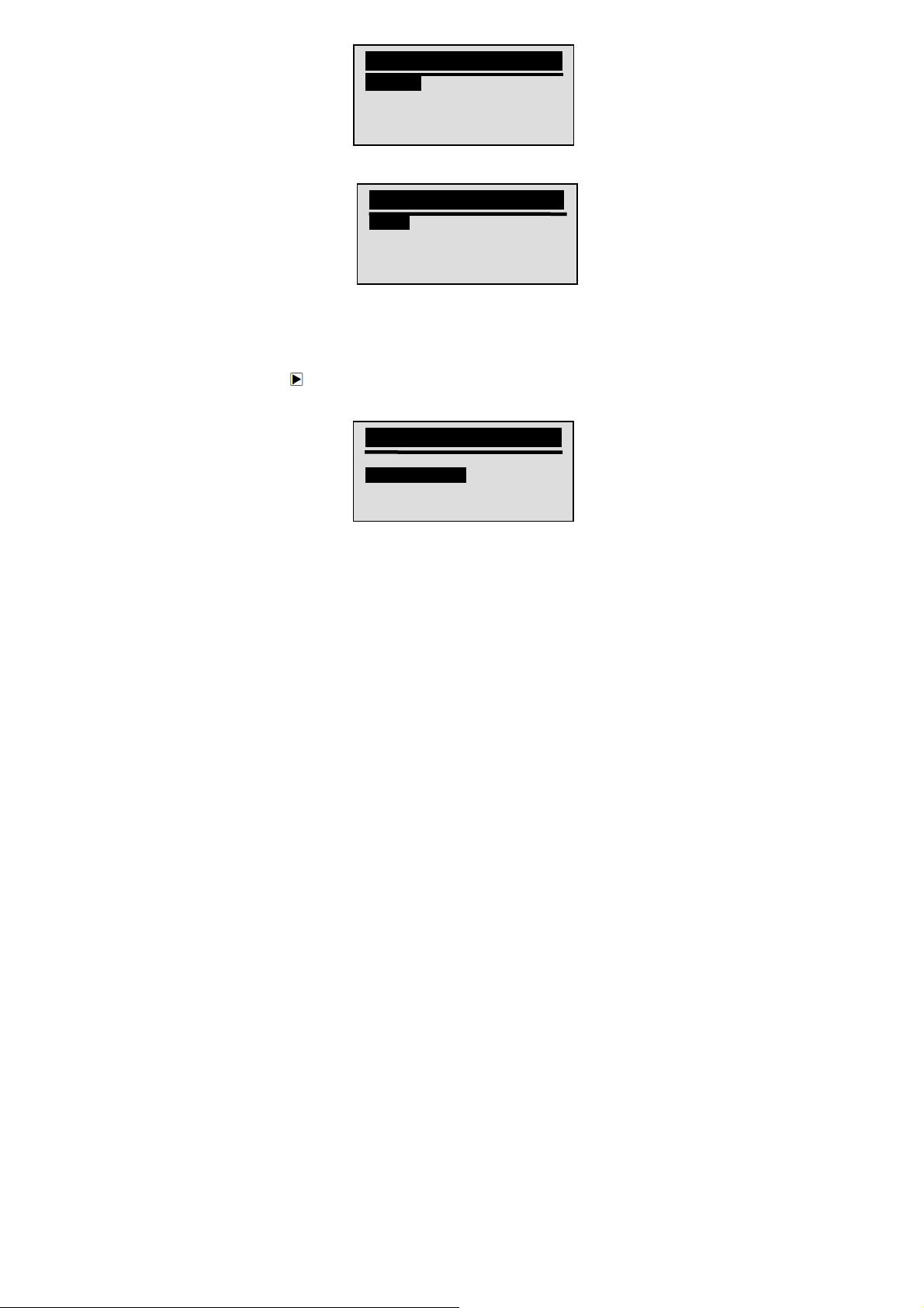
3. Use the SCROLL key to select desired language.
4. Press the YES/NO key to save language setting and
Changing Measurement Unit
√ Metric is the default measurement unit.
To change measurement unit:
1. Use the SCROLL key to select Measurement Unit from
2. Press the YES/NO key to confirm.
3. Use the SCROLL key to select desired measurement
VS70 OBDII/EOBD Code Reader User’s Guide_English Version_V1.10
System Setup
Language
Measurement Unit
Contrast
Exit
Language
English
Espanol
Francais
return.
System Setup
screen.
System Setup
Language
Measurement Unit
Contrast
Exit
unit.
14
Page 12
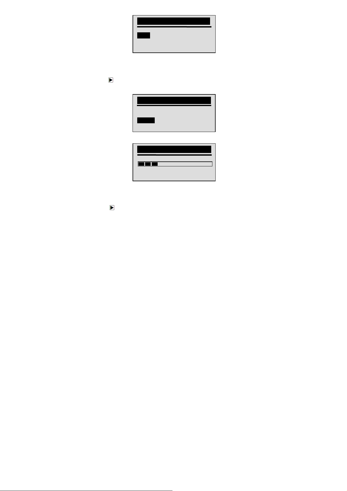
4. Press the YES/NO key to save measurement setting
Adjusting Display Contrast
To adjust display contrast:
1. Use the SCROLL key to select Contrast from
2. Press the YES/NO key to confirm.
3. Use the SCROLL key to adjust contrast.
4. Press the YES/NO key to save contrast setting and
Exiting System Setup
To quit system setup:
1. Use the SCROLL key to move Exit from
2. Press the YES/NO key to confirm and exit.
VS70 OBDII/EOBD Code Reader User’s Guide_English Version_V1.10
Measurement Unit
English
Metric
and return.
Setup
screen.
System Setup
Language
Measurement Unit
Contrast
Exit
Contrast
Contrast (30%)
[SCROLL] – Adjust
[YES/NO] – Save
return.
screen.
15
System Setup
System
Page 13
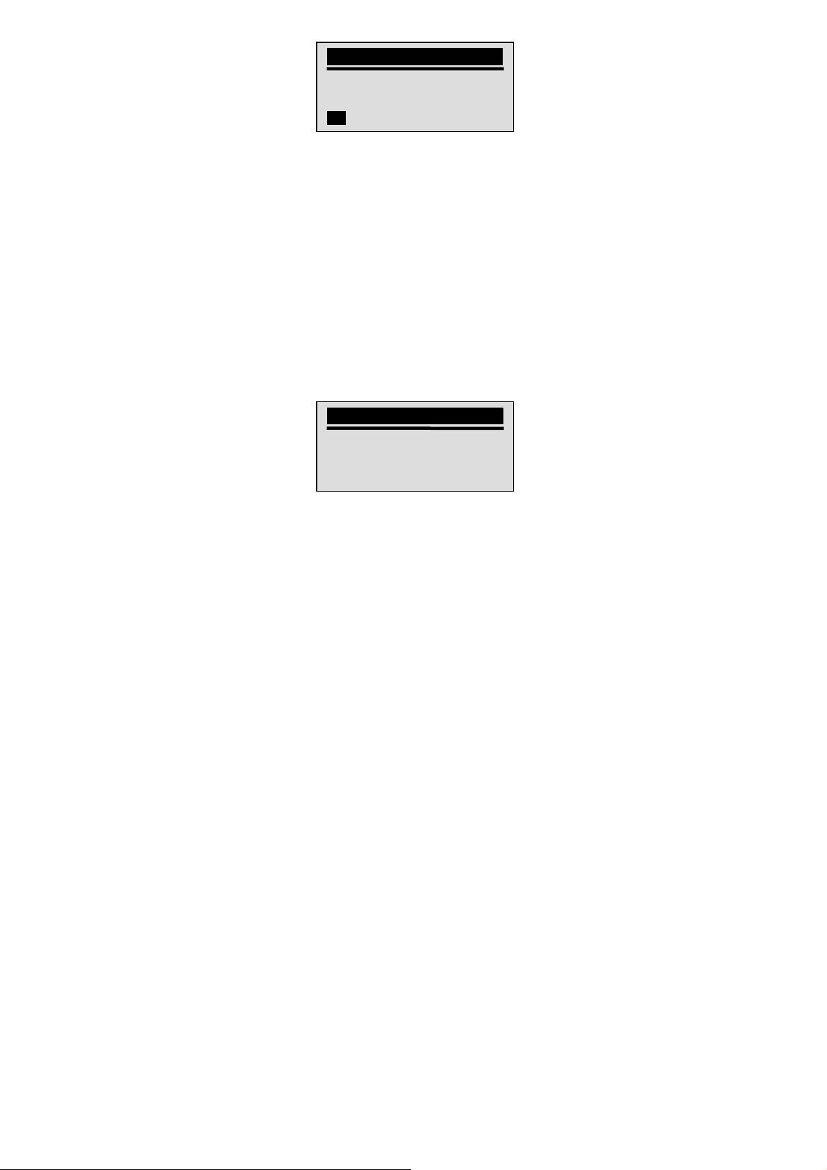
System Setup
Language
Measurement Unit
Contrast
Exit
5. OBDII/EOBD Diagnosis
Diagnostic Menu
● Read DTCs.
● Clear DTCs.
● View live datastream.
● View freeze data.
● Retrieve vehicle information.
√ The code reader detects the communication protocol
when it is connected to the vehicle and uses the
protocol throughout the testing till another vehicle is
diagnosed.
√ If the code reader fails to communicate with the vehicle a
“Communication Error!” message displays. Make sure
the OBDII connector is securely attached, and the
ignition key is on. Turn vehicle key to off for 10 seconds,
then on. If problem still exists, refer to “Error Messages”
on page 33 of Troubleshooting.
√ When the code reader links to vehicle, it checks the
status of I/M Monitors, and gives a summary report on
the display as illustrated below.
√ If vehicle is equipped with more than one computer
VS70 OBDII/EOBD Code Reader User’s Guide_English Version_V1.10
allows you to:
System Status
Code Found 3
Monitors N/A 4
Monitors OK 4
Monitors INC 3
16
Page 14

module (for example a powertrain control module [PCM]
and a transmission control module [TCM]), the code
reader identifies them by their identification names (ID)
assigned by manufacturer (i.e. Engine or A/T).
√ Use the SCROLL key to select a control module where
the data may be retrieved when more than one module
is detected.
Control Module
Engine
A/T
Exit
√ To view information of other control unit quit current test
and select another module.
5.1 Reading DTCs
The
Read Codes
codes), which are used to help identify the cause of a trouble
or troubles with a vehicle, and pending codes from the
vehicle’s control modules.
√ When emission-related or drivability fault occurs the
control module illuminates the malfunction indicator
lamp (MIL).
√ Pending Codes are also referred to as continuous
monitor or maturing codes that indicate intermittent
faults. If the fault does not occur within a certain
number of drive cycles (depending on vehicle), the
code clears from memory. If fault occurs a specific
number of times, the code matures into a DTC and the
MIL illuminates or blinks.
√ This function can be performed with KOEO or KOER.
To read codes from vehicle control modules:
1. Press the YES/NO key to start diagnosis from home
screen.
2. Use the SCROLL key to select Read Codes from
Diagnostic Menu
VS70 OBDII/EOBD Code Reader User’s Guide_English Version_V1.10
function is used to read DTCs (stored
screen.
17
Page 15

Diagnostic Menu
Read Codes
Clear Codes
Datastream
Freeze Data
3. Press the YES/NO key to confirm.
4. View DTCs and their definitions.
√ If no DTCs are present a message stating “No (Pending)
√ If any manufacturer specific or enhanced codes detected,
√ If manufacturer of the vehicle being tested is not list,
5. Press the YES/NO key to return to
$10 1/2
P0101 Generic
Mass or Volume Air
Flow A Circuit Range
/ Performance
Codes Found” is displayed.
a “Manufacturer specific codes are found! Press any key
to select vehicle make!” message displays prompting
you to select vehicle make before viewing DTC(s).
select Other.
screen.
Diagnostic Menu
5.2 Clearing DTCs
The
Clear Codes
Readiness data from vehicle’s control module(s). It may also
erase freeze data, and set monitors to incomplete or not ready.
√ Perform
been checked completely.
√ After servicing the vehicle, erase stored DTCs and verify
no codes have been reset. If a DTC returns, problem
VS70 OBDII/EOBD Code Reader User’s Guide_English Version_V1.10
function is used to delete DTCs and I/M
Clear Codes
function only after systems have
18
Page 16
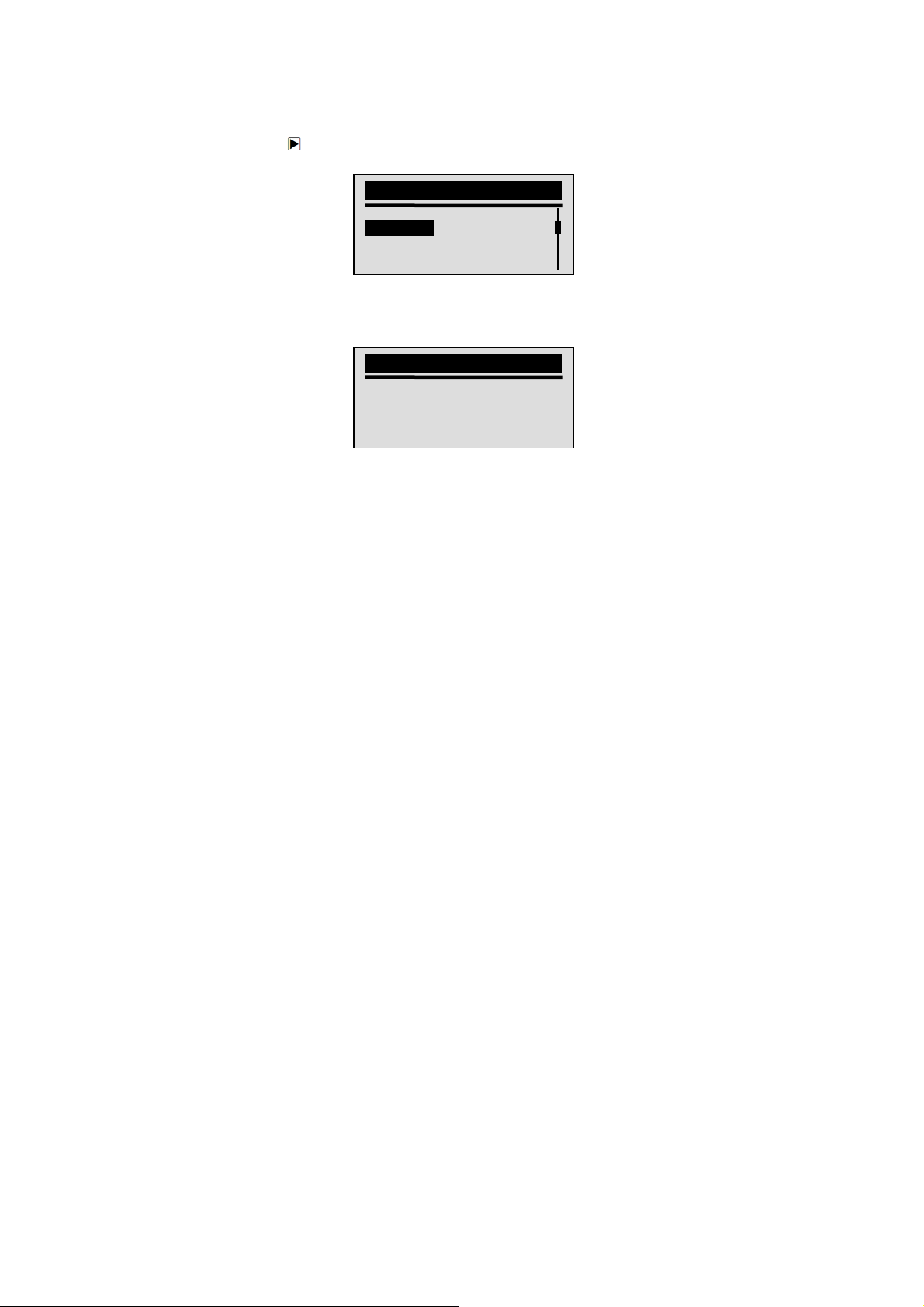
has not been fixed or other faults are present.
√ Depending on which monitor sets a code the vehicle may
need to be driven and the monitor ran before
concluding that the fault is repaired.
√ This function is performed with KOEO. Do not start the
engine.
To erase codes from vehicle control modules:
1. Use the SCROLL key to select Clear Codes from
Diagnostic Menu
Diagnostic Menu
Read Codes
Clear Codes
Datastream
Freeze Data
2. Press the YES/NO key to confirm.
3. If codes and diagnostic results are to be cleared, use
the SCROLL key to select YES and press the YES/NO
key.
√ If codes and test data not to be deleted, select NO, and a
4. Wait a few seconds until a “Codes Cleared!” message
√ If the code reader fails to clear the codes, a “Clear Error!
5. Wait a few seconds or press any key to return to
VS70 OBDII/EOBD Code Reader User’s Guide_English Version_V1.10
Clear Code
“Command Cancelled!” message displays prompting to
press any key to return to
shows indicating codes are cleared successfully.
Turn Key on with Engine off!” message displays.
Diagnostic Menu
screen.
Are You Sure to
Clear Codes?
<YES> NO
Diagnostic Menu
.
19
.
Page 17
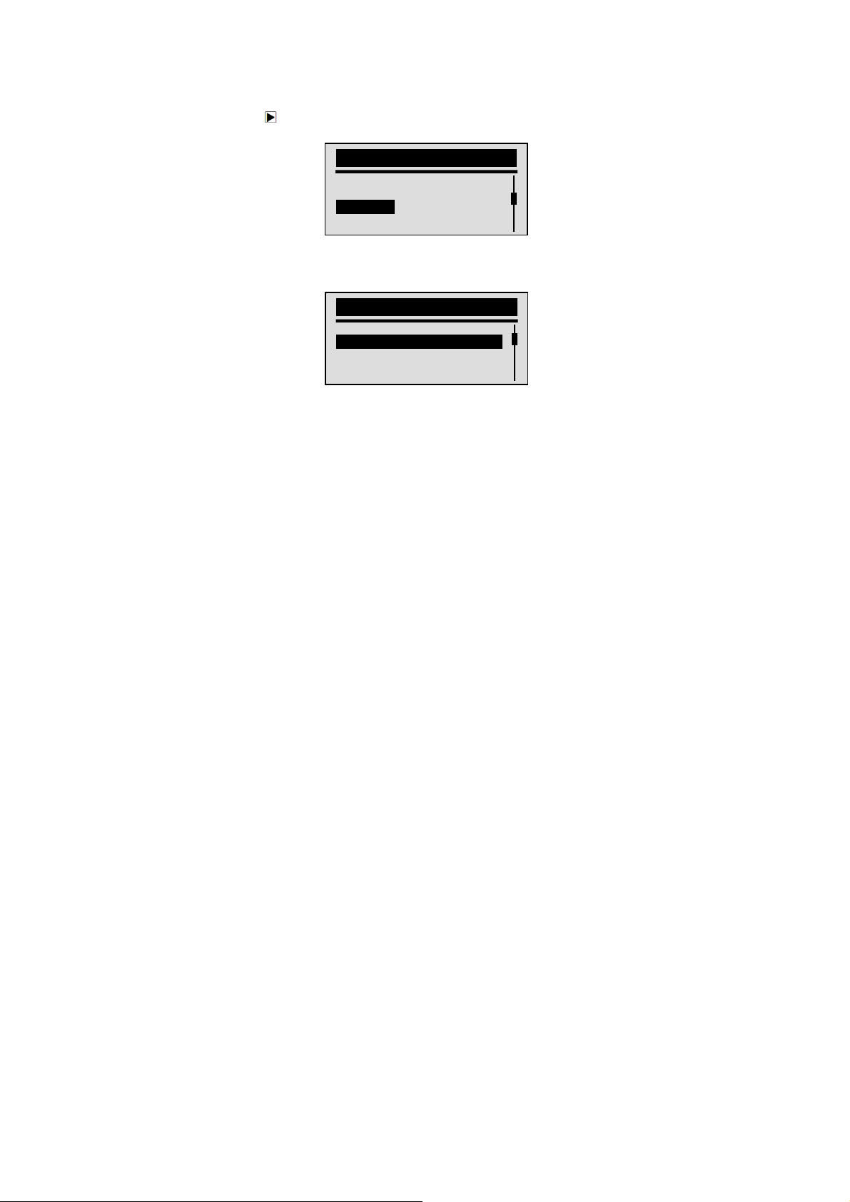
5.3 Viewing Datastream
The
Datastream
vehicle’s electronic control unit’s PID data, including sensor data,
operation of switches, solenoids and relays.
To view live datastream:
1. Use the SCROLL key to select Datastrean from
Diagnostic Menu
2. Press the YES/NO key to confirm.
3. View PIDs on code reader. Use the SCROLL key when
more than one screen of information is retrieved.
√ Some vehicle may not support this function, and a “Not
Support This Function!” message display.
4. Press the YES/NO key to return.
function allows real time viewing of the
screen.
Diagnostic Menu
Read Codes
Clear Codes
Datastream
Freeze Data
Datastream
DTC_CNT 2
LOAD_PCT % 0.0
ETC ℉ 171
RPM/min 0
5.4 Viewing Freeze Data
The
Freeze Data
snapshot of vehicle operating conditions recorded by the
on-board computer at the time of an emission-related fault.
√ If codes were cleared, freeze data may not be stored in
vehicle memory depending on vehicle.
VS70 OBDII/EOBD Code Reader User’s Guide_English Version_V1.10
function is used to view freeze frame data, a
20
Page 18

To view freeze frame data:
1. Use the SCROLL key to select Freeze Data from
Diagnostic Menu
Diagnostic Menu
Read Codes
Clear Codes
Datastream
Freeze Data
2. Press the YES/NO key to confirm.
3. View freeze frame data on screen. If more than one
screen of information is retrieved, use the SCROLL key
to view additional data.
√ If no freeze frame detected, a “No Freeze Data Found!”
√ Some vehicle may not support this function, and a “Not
4. Press the YES/NO key to return to
Freeze Data
DTCFRZF P0157
FUELSYS1 OL
FUELSYS2 OL
LOAD_PCT (%) 0.0
message displays.
Support This Function!” message display.
screen
Diagnostic Menu
.
5.5 Reading I/M Readiness Status Data
The
I/M Readiness
operations for the emission system on OBDII/EOBD vehicles.
√ I/M Readiness is a useful function used to check if all
monitors are OK or N/A.
√ The vehicle’s computer performs tests on the emission
system during normal driving conditions. After a
specific amount of drive time (each monitor has specific
VS70 OBDII/EOBD Code Reader User’s Guide_English Version_V1.10
function is used to view a snapshot of the
21
Page 19
A
p
A
A
driving conditions and time required), the computer’s
monitors decide if the vehicles emission system is
working correctly. When the monitor’s status is:
● OK - vehicle was driven enough to complete the
monitor.
● INC (Incomplete) - vehicle was not driven enough to
complete the monitor.
● N/A (Not Applicable) - vehicle does not support that
monitor.
√
I/M Readiness
KOEO.
√ There are two types of I/M Readiness tests:
● Since DTCs Cleared - shows status of the monitors
since the DTCs were last cleared.
● This Drive Cycle - shows status of monitors since the
start of the current drive cycle.
√ Below is a list of abbreviations and names of OBD II
monitors supported by the code reader.
No.
bbreviation Name
1 Misfire Monitor Misfire Monitor
2 Fuel System Mon Fuel System Monitor
Comp.
3
Com
onent
4 Catalyst Mon Catalyst Monitor
5 Htd Catalyst Heated Catalyst Monitor
Evap System
6
Mon
7 Sec Air System Secondary Air System Monitor
8
/C Refrig Mon
Oxygen Sens
9
Mon
10 Oxygen Sens Htr Oxygen Sensor Heater Monitor
EGR System
11
Mon
NOTE Not all monitors are supported by all vehicles.
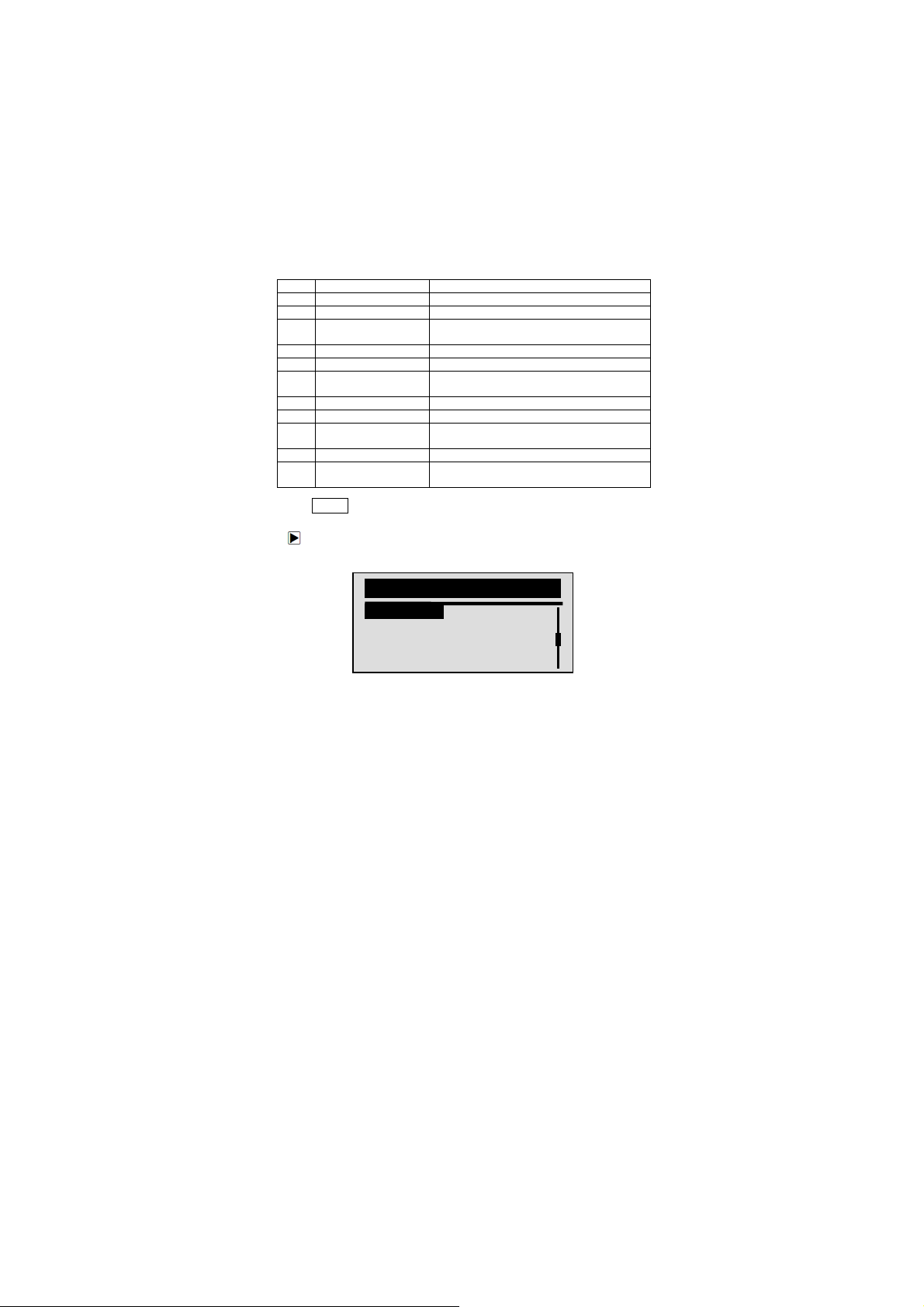
To retrieving I/M Readiness Status data:
1. Use the SCROLL key to select I/M Readiness from
Diagnostic Menu
VS70 OBDII/EOBD Code Reader User’s Guide_English Version_V1.10
function is performed with the KOER or
Comprehensive Components
Monitor
Evaporative System Monitor
ir Conditioning Refrigerant Monitor
Oxygen Sensor Monitor
Exhaust Gas Recirculation System
Monitor
screen.
Diagnostic Menu
22
I/M Readiness
Vehicle Information
Exit
Page 20
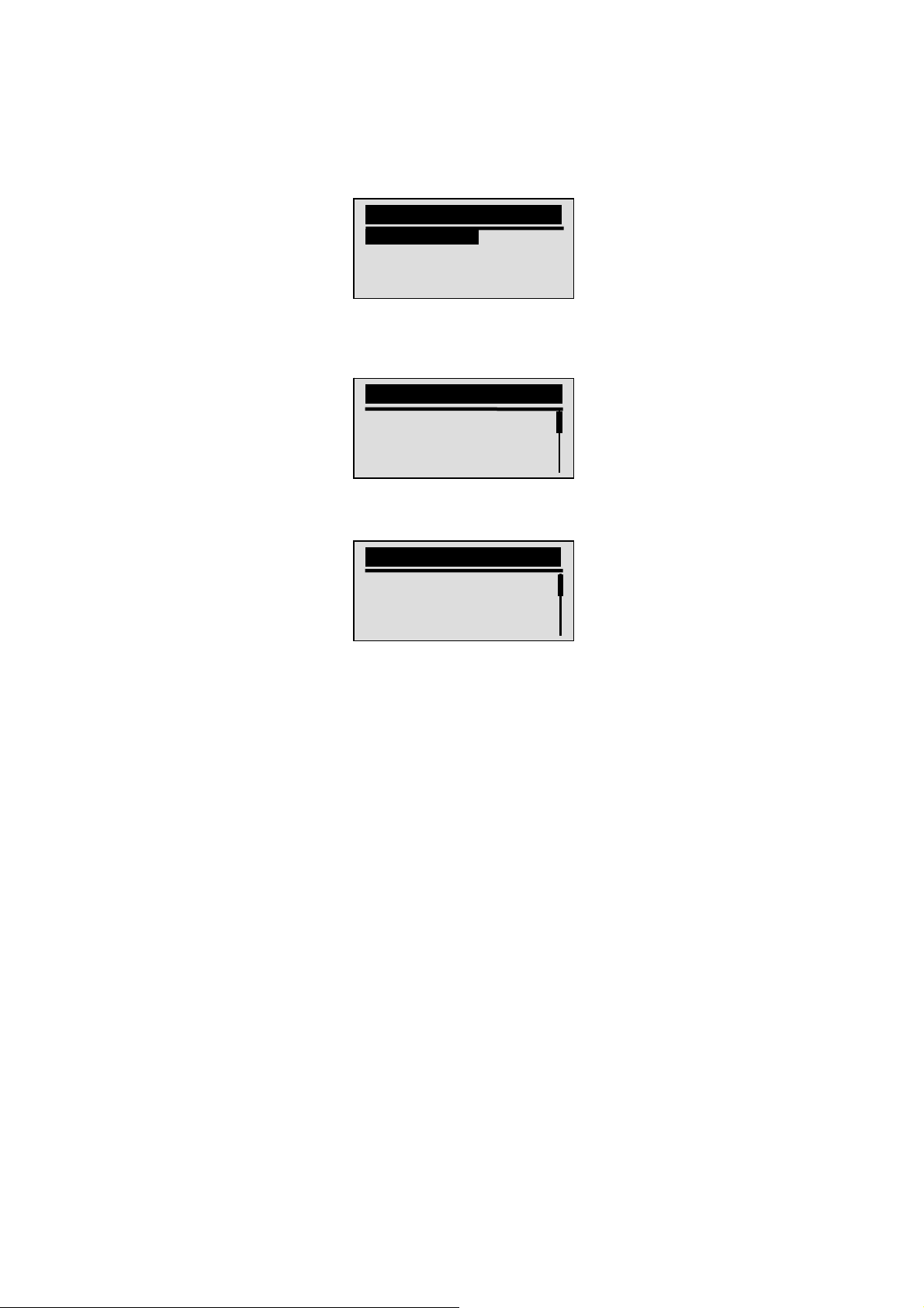
2. Press the YES/NO key to confirm.
√ If vehicle supports both types of monitors, please
following screen:
√ Use the SCROLL key to select a monitor type and press
3. Depending on readiness test, one of these 2 screens
Or
VS70 OBDII/EOBD Code Reader User’s Guide_English Version_V1.10
I/M Readiness
Since DTCs Cleared
This Drive Cycle
Exit
the YES/NO key to confirm.
will be present.
Since DTCs Cleared
MIL Status OFF
Misfire Monitor N/A
Fuel System Mon N/A
Comp. Component OK
This Drive Cycle
MIL Status OFF
Misfire Monitor N/A
Fuel System Mon N/A
Comp. Component OK
23
Page 21
√ If more than one screen of information is retrieved, use
the SCROLL key to view additional data.
√ Some vehicle may not support this function, and a “Not
Support This Function!” message display.
4. Press the YES/NO key to return to
Diagnostic Menu
.
5.6 Reading Vehicle Information
The
Vehicle Information
VIN number, calibration ID(s) which identifies software version
in vehicle control module(s), calibration verification numbers
(CVN(s)) and in-use performance tracking on model year 2000
and newer OBD II compliant vehicles.
√ CVNs are calculated values required by OBD II
regulations. They are reported to check if
emission-related calibrations have been changed.
Multiple CVNs may be reported for a control module. It
may take several minutes to do the CVN calculation.
√ In-use performance tracking tracks performance of key
readiness monitors.
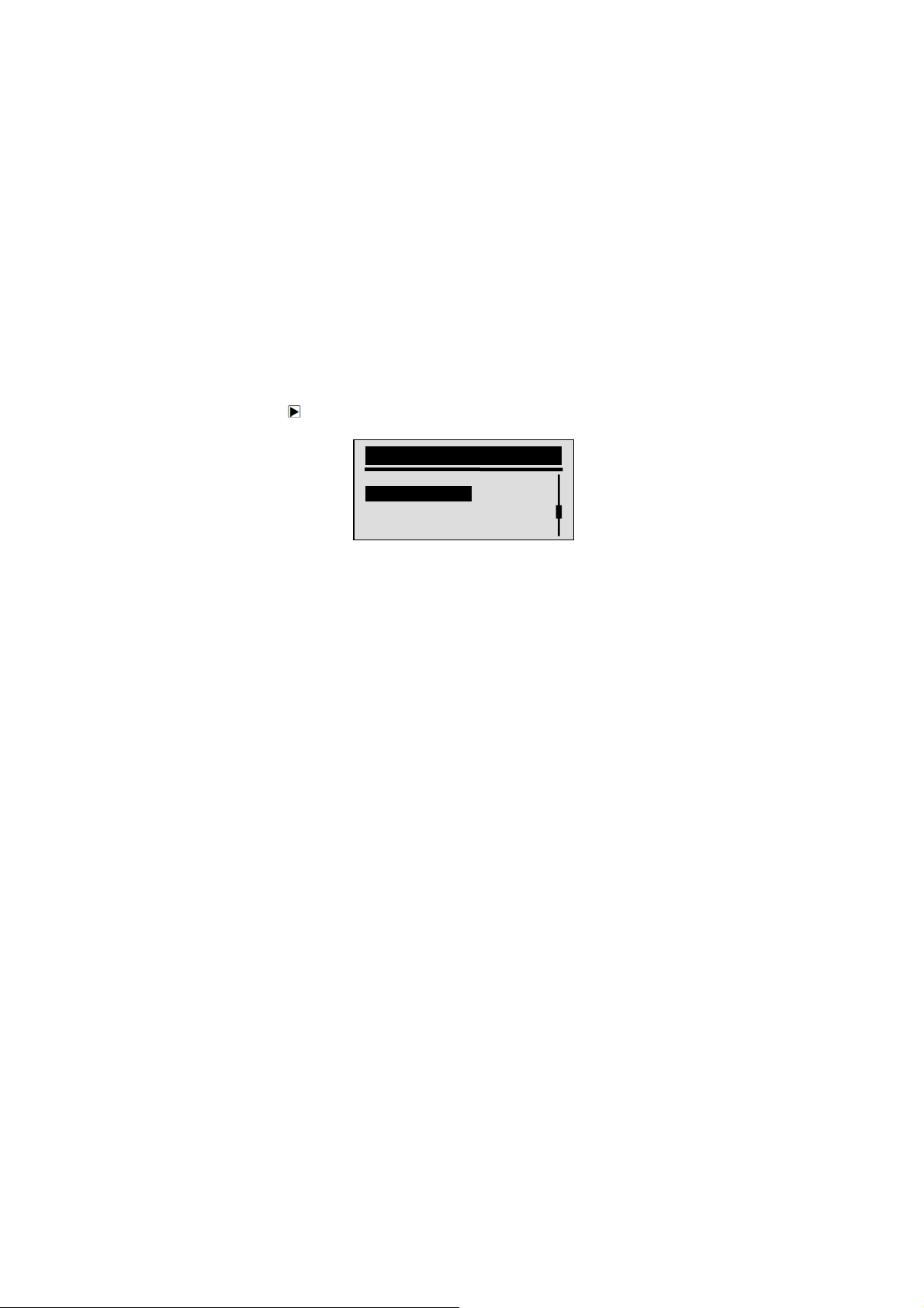
To request vehicle information:
1. Use the SCROLL key to select Vehicle Information from
Diagnostic Menu
Diagnostic Menu
I/M Readiness
Vehicle Information
Exit
2. Press the YES/NO key to confirm.
3. Wait a few seconds or press YES/NO key to continue.
VS70 OBDII/EOBD Code Reader User’s Guide_English Version_V1.10
function is used to request the vehicle’s
screen.
24
Page 22
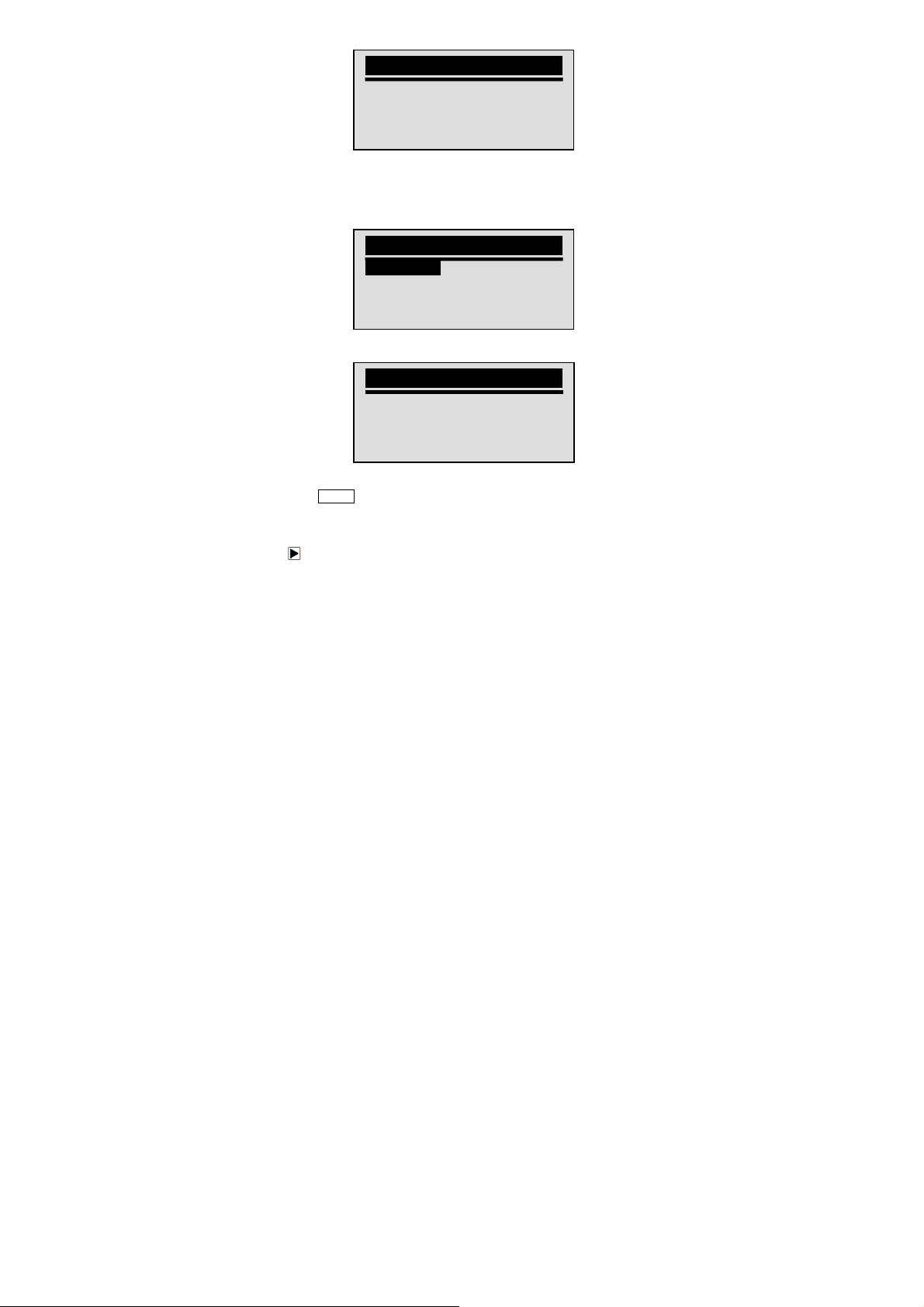
√ Some vehicle may not support this function, and a “Not
4. Use the SCROLL key to select an available item from
5. Press the YES/NO key to view retrieved information.
6. Press the YES/NO key return.
NOTE Not all data is supported by all vehicles.
Vehicle Information
Turn Key on
with Engine off!
Any key to continue.
Support This Function!” message display.
Vehicle Information
Vehicle Information
Calibration ID
Cal. Verif. Number
Exit
screen.
Calibration ID
Cal ID1:
09G927750EK_0706
5.7 Exiting Test
To exit OBDII test:
1. Use the SCROLL key to select Exit from
Menu
screen.
VS70 OBDII/EOBD Code Reader User’s Guide_English Version_V1.10
25
Diagnostic
Page 23

Diagnostic Menu
I/M Readiness
Vehicle Information
Exit
2. Press the YES/NO key to confirm.
3. To quit test, use the SCROLL key to select YES and
press YES/NO key.
√ If not to exit, use the SCROLL key the select NO and
Exit Test
Are You Sure to
Exit Test?
<YES> NO
press the YES/NO key.
6. Updating the Code Reader
VS70 is able to be updated to keep you stay current with the
latest development of diagnosis.
√ The update of VS70 consists of two parts: program
upgrade and DTC upgrade.
√ To update the code reader, you need following tools:
● VS70 Code Reader
● Update Tool FoxLink
● PC or Laptop with USB Ports and Internet Explorer
● USB Cable
√ To be able to use update tool, PC or laptop must meet
the following minimum requirements:
● Operation System: Win98/NT, Win ME, Win2000, Win
XP, VISTA and Windows 7.
● CPU: Intel PIII or better
VS70 OBDII/EOBD Code Reader User’s Guide_English Version_V1.10
26
Page 24
● RAM: 64MB or better
● Hard Disk Space: 30MB or better
● Display: 800*600 pixel, 16 byte true color display or
better
● Internet Explorer 4.0 or newer
IMPORTANT Do not disconnect the code reader from
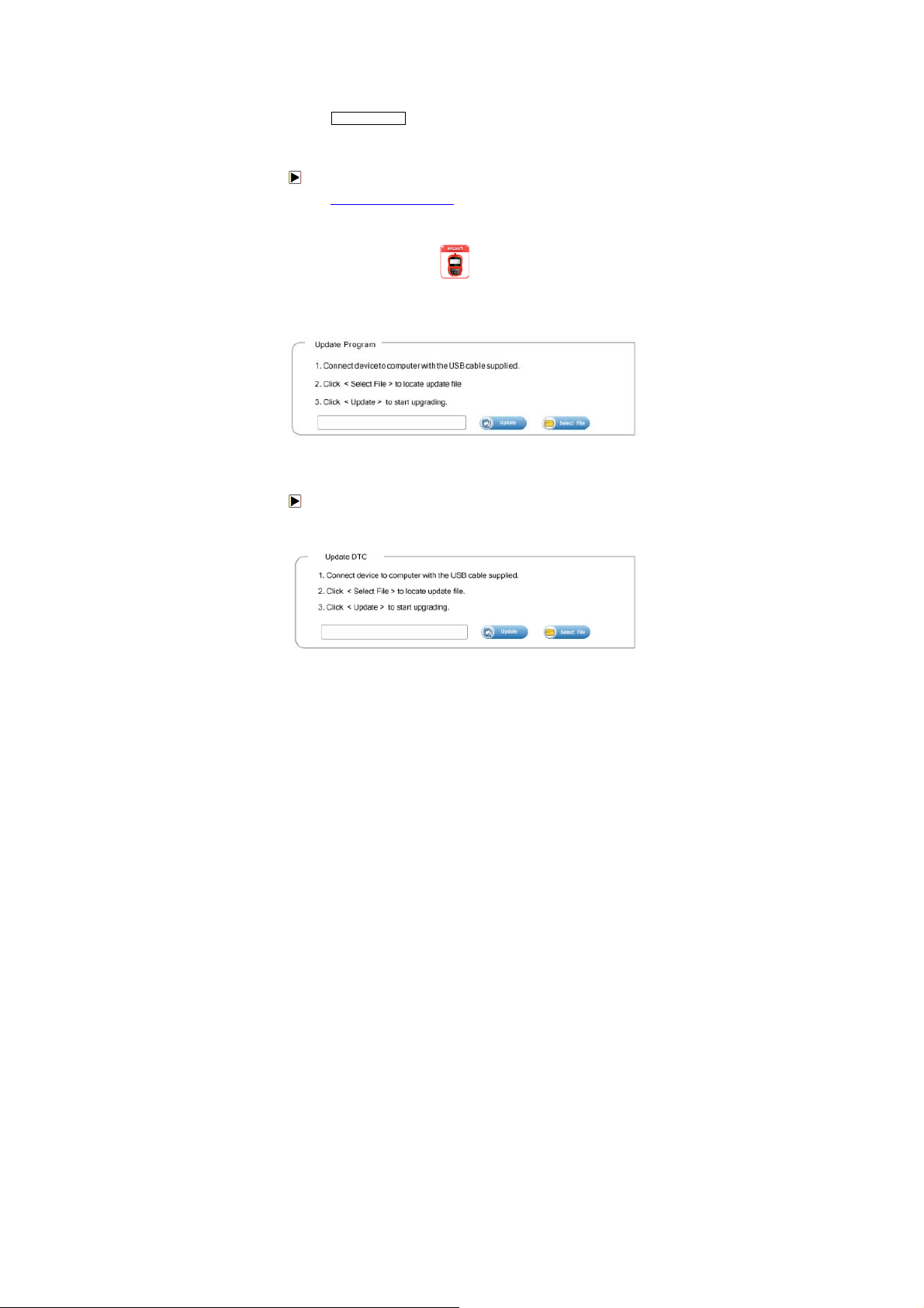
To update program:
1. Download the update tool FoxLink and update files from
our site
www.silverado.com.cn and save the applications and
files in computer disk.
2. Unzip the update tool file. Follow instructions on
computer screen to install the tool and driver.
3. Double click the desktop icon to launch the
application.
4. Connect VS70 to computer with the USB cable provided
and the application detect the device automatically.
5. Use <Select File> to locate update file downloaded.
6. Click <Update> to start updating.
To update DTCs:
√ It may takes several minutes to update the DTCs.
1. Use <Select File> to locate update file downloaded.
VS70 OBDII/EOBD Code Reader User’s Guide_English Version_V1.10
computer, or power off the computer
during the process of updating.
27
Page 25

2. Click <Update> to start updating.
7. Troubleshooting
7.1 Error Message
When a “Communication Error!” message displays, please
check the following:
● Verify ignition key is in the ON position.
● Make sure the code reader is correctly attached to
vehicle’s Data Link Connector (DLC).
● Check DLC for cracked or recessed pins, or for any
substance that could prevent a good electrical
connection.
● Check VS70’s OBDII connector for bent or broken
pins.
● Make sure the vehicle is OBDII/EOBD compliant.
● Cycle the vehicle key to OFF for 10s and then back to
ON.
● Verify battery voltage is at least 8.0V with KOEO.
● Verify that the control module is not defective.
7.2 Code Reader Does Not Power Up
If VS70 will not power up, communicate with vehicle’s control
module, or functions incorrectly in any other way, do the
following:
● Check DLC for broken or bent pins and clean the pins
if need be.
● Make sure VS70 is correctly connected to vehicle’s
DLC.
● Verify battery voltage is at least 8.0V with KOEO.
VS70 OBDII/EOBD Code Reader User’s Guide_English Version_V1.10
28
 Loading...