

Page 1
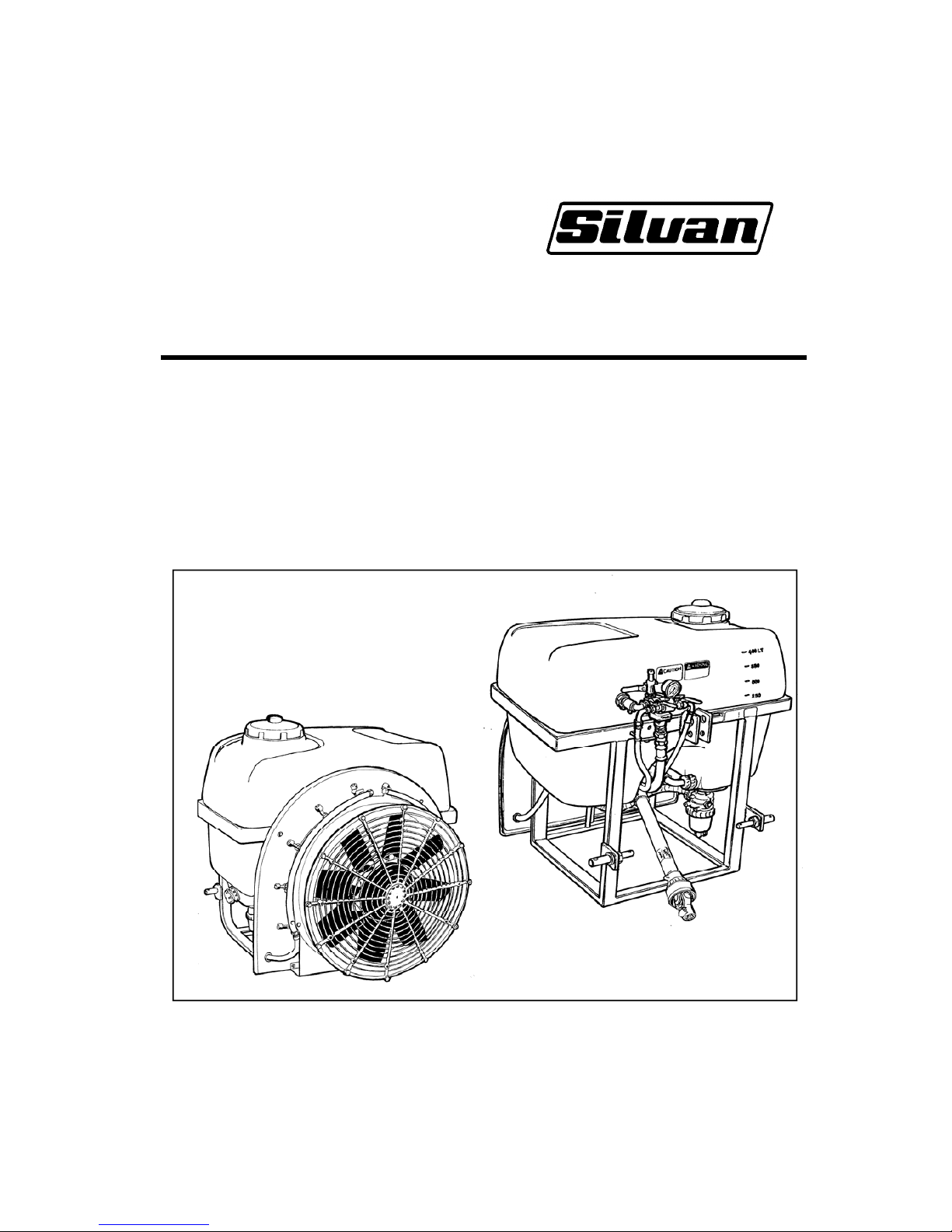
Operator’s Manual
Suntuff Linkage Airblast Sprayers
200 litres
400 litres
500 litres
MANAB06 Rev D 30/01/2006
Page 2

Page 1
Warranty
Introduction 1
New Product Warranty Policy 2
Specifications 3
Safety Information 4
Operation
Attaching to the Tractor, PTO Drive 7
Starting the Sprayer 7
Control Units - 2 and 3 outlet 8
Flip On/Off Nozzles 9
Nozzle Selection and Calibration
Nozzle Selection, Checking Calibration 10
When to Spray, Nozzle Selection Tables 11
Examples and Calibration Worksheets 12
Optional Equipment
Two Side Conveyor, Single Side Conveyor 14
Electric Cabin Controls 14
Trouble Shooting 15
Lubrication and Maintenance 16
Warranty Certificate 17
Contents
Introduction
Silvan is an Australian owned company
specialising in the supply of crop protection
equipment to primary producers. A leader in the
design of agricultural sprayers, the company was
established in 1962 and has grown to become
the largest manufacturer and supplier of crop
protection equipment in Australia.
This manual covers the 200, 400 and 500 litre
sizes of Suntuff Linkage Airblast Sprayers. These
Silvan sprayers and associated equipment are
designed and manufactured to provide a high
standard of performance and safety and
incorporate many innovative features. To ensure
continued efficient performance and safe
operation, you need to read this manual
thoroughly and fully familiarise yourself with all
aspects of your sprayer’s operation, maintenance
and safety procedures.
Now that you’re a proud Silvan owner, all our
services and dealer support are available to you
should you need them. We assure you of our
best attention at all times.
Page 3
Page 2
New Product Warranty
the Silvan
Warranty
This warranty is the only warranty applicable to Silvan new products ('Products') and, to the
maximum extent permitted by law, is expressly in lieu of any other conditions or warranties
expressed or implied in relation to the Products.
Subject only to legislative obligations to the contrary, Silvan shall not be liable for incidental or
consequential damage resulting from ownership or use of a Product.
Silvan does not authorize any person to create for it any other obligation or liability in connection
with these products.
Silvan warrants its authorised Dealer, who in turn warrants the original purchaser (owner) of each new
Silvan product that it will repair or replace the product, or, pay the cost of repair or replacement, as
determined by Silvan without charge for labour or any defective or malfunctioning parts in accordance
with the warranty limitations and adjustment schedule below.
The warranty period begins on the date the product is delivered to the first retail purchaser for a period of
12 months
This Warranty Covers
Only conditions resulting directly from defects in workmanship or material under normal use and service.
Warranty Exclusions
The Warranty does not cover:
Conditions resulting from misuse, use of incompatible chemicals, exceeding machine
specifications including overloading, impact damage, negligence, accidental damage or failure to
perform recommended maintenance services.
Any product which has been repaired by other than an authorised Silvan service outlet in a way
which, in the sole and absolute judgement of Silvan, adversely affect its performance or
reliability.
The replacement of maintenance items such as diaphragms, batteries, V belts and ground
engaging components, etc.
Loss of time, inconvenience, loss of use of the product liability to third parties or any other
consequential damages.
Incidental costs associated with a warranty repair including any travel costs, out of hour’s labour
charges, cleaning costs, transportation costs, freight costs or any communication costs.
The repair of a defective product qualifying under this warranty will be performed by any authorised
Silvan service outlet within a reasonable time following the delivery of the product, at the cost of the
owner, to the service outlet’s place of business. The product will be repaired or replaced, using new parts
supplied by Silvan. Silvan, in its absolute discretion, may choose to pay the cost of replacement or repair
of the product.
The owner is responsible for the performance of regular maintenance services as specified in the
Owner/Operator Manual applicable to the product. Failure to carry out regular maintenance may
invalidate warranty
Page 4

Page 3
Specifications
General
Silvan Suntuff Linkage Airblast sprayers are for
use in the application of agricultural chemicals in
orchards and vineyards. The sprayers use a high
pressure pump and nozzles to atomise the
chemical solution, together with a high volume
axial flow air fan to distribute the spray.
Tank
Polytuff impact resistant polyethylene.
Capacity 200, 400, or 500 litres with calibrated
level indicator.
Offset, non spill screw down lid of 255 mm
diameter with basket strainer.
Continuous by-pass agitation in bottom of tank.
Pump
Constant displacement oil backed diaphragm
pump of varying size depending on sprayer
model and specification. Nitrile diaphragm and
corrosion resistant, anodised aluminium body.
Sprayer Model Pump Model
200 litre MP-40
400 litre MP-40 or APS-71
500 litre APS-96
Pump output and maximum operating pressure
at 540 PTO rpm as shown below.
Pump No. Output Max. Pressure
l/min gpm Bar psi
MP-40 40 8.6 30 435
APS-71 71 15.6 40 580
APS-96 95 21.0 40 580
Fan
Axial flow type of varying diameter depending on
sprayer model. Cast aluminium hub with 8 nylon
blades, polyethylene backing plate with
galvanised steel cowling and protective mesh
cover.
Sprayer Model Fan Diameter
200 litre 600 mm
400 litre 700 mm
500 litre 800 mm
PTO Drive
Quality 540 rpm telescopic drive PTO shaft with
safety shields.
Fan Gearbox
Single speed, oil bath type with neutral position.
Fan speed 2484 rpm at 540 rpm PTO speed.
Controls
Manual by-pass to tank.
Screw type pressure regulator.
Glycerine filled pressure gauge.
2 outlet valves with MP-40 pump.
3 outlet valves with APS-71 and APS-96 pump.
Nozzles
Screw mounted, brass body with removable
ceramic jets and stainless steel swirl plates.
Flip over action to turn nozzle on or off.
Larger models fitted with twin jet nozzles for easy
changing of application rate.
Fan Size No. Nozzles Nozzle Type
600 mm 10 (5 per side) Single jet
700 mm 12 (6 per side) Twin jet
800 mm 14 (7 per side) Twin jet
Filtration
Three stage with removable elements.
Tank lid strainer 18 mesh.
Suction line filter 50 mesh (blue).
Nozzle strainers stainless steel.
Pressure Hoses and Spray Lines
MP-40 pump -High pressure PVC hose.
APS-71 & APS-96 -Wire braided hydraulic
pressure hose and swaged fittings
Stainless steel spray lines.
Frame and Hitch
Heavy duty galvanised steel construction.
Category I linkage on 200 litre unit.
Reversible Category I and II linkage pins on 400
and 500 litre sprayers.
Optional Equipment
Two sided vineyard conveyor.
Single side conveyor for trees.
Electric cabin control unit.
Pentomatic single lever control valve.
Dimensions and Weights
With PTO drive and standard equipment fitted.
Length L, width W, height H, all in (mm).
Mass M (kg) with tank empty.
To calculate gross mass with tank filled add 1 kg
per litre of tank capacity.
e.g. for 200 litres add 200kg.
L W H M
200 litre 1070 1000 1000 75
400 litre 1330 1190 1200 134
500 litre 1400 1190 1325 137
Power Requirement
Minimum tractor PTO horsepower at 540 rpm.
200 and 400 litre 20 HP
500 litre 25 HP
Page 5
Page 4
Safety Information
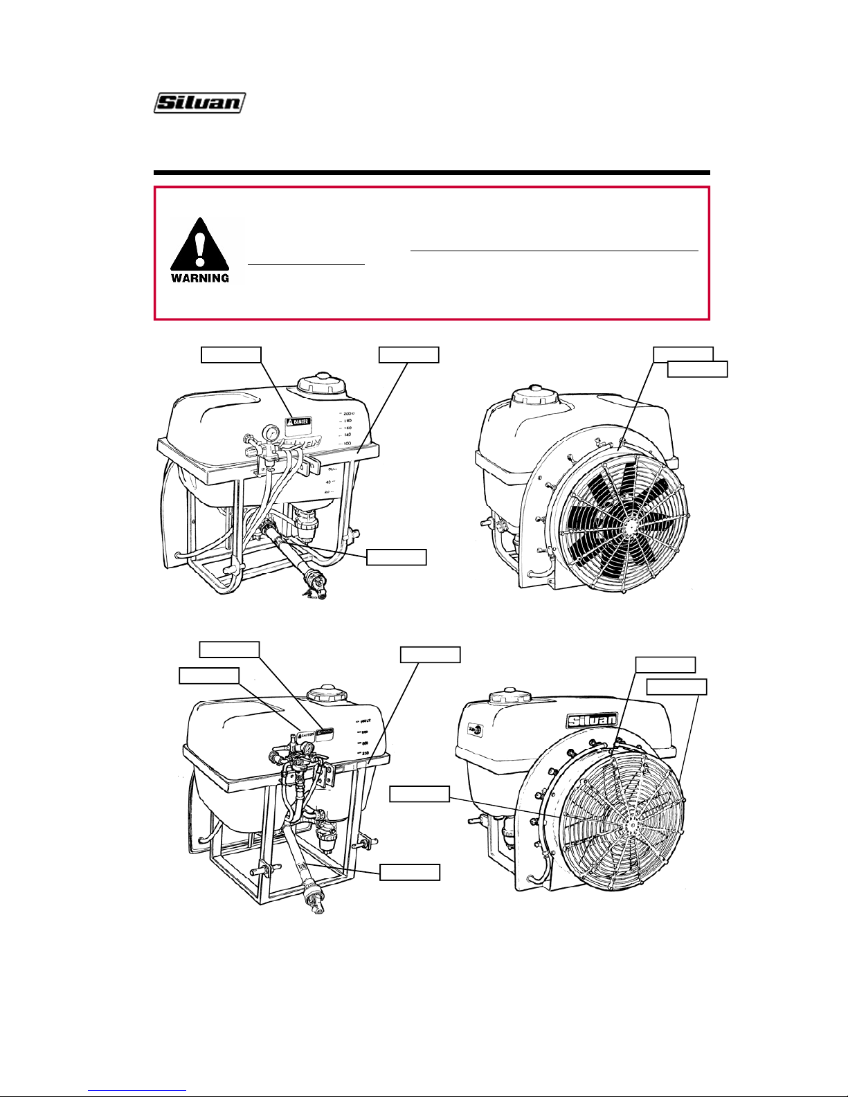
The location of the safety decals fitted to Suntuff Linkage Airblast sprayers is shown
in the diagrams below and their wording is shown on the page opposite.
It is important that all operators read and follow the information on all safety decals
before operating the sprayer. Failure to comply with these warnings could result in
serious injury or death.
Safety decals should be kept clean and legible at all times. If any decals are missing
or unreadable they should be replaced by ordering new decals from your Silvan
dealer using the part numbers shown below.
DEC 10
399 14 1000
DEC 12 DEC 48
200 LITRE SPRAYER
FRONT VIEW REAR VIEW
DEC 10
399 14 1000
DEC 13
DEC 12
400 & 500 LITRE SPRAYER
FRONT VIEW REAR VIEW
DEC 48
DEC 12
DEC 68
DEC 68
Page 6

Page 5
Part Number DEC 10
Safety Information
Part Number DEC 12
Part Number DEC 48
Part Number 399 14 1000
Part Number DEC 13
Part Number DEC 68
Page 7
Page 6
Safety Information
Before operating the sprayer read the following safety instructions.
Failure to comply with these warnings may result in serious injury or death.
Whilst your Silvan Suntuff Linkage Airblast Sprayer has been designed and manufactured to incorporate
all necessary safety features it is essential that any person who operates or works on the machine is
aware of the safety precautions that should be exercised.
S This sprayer is designed and manufactured
solely for the purpose of applying agricultural
chemicals to crops. Under no circumstances
should it be used for any other purpose.
S Before using the sprayer carefully read and
ensure you understand the contents of this
manual and any other manual supplied with
the sprayer.
S Before operating the sprayer read all the
safety warnings which are carried on various
parts of the machine. Refer to the next page
for the wording of these warnings.
S Never allow an inadequately trained person
to attach or operate the sprayer.
S Do not operate the sprayer whilst wearing
loose clothing, unrestrained long hair,
jewellery or anything which could become
entangled in rotating components or limit
your vision.
S Wear ear protection when operating the
sprayer on a tractor which is not fitted with a
sound proofed cabin.
S Ensure the linkage capacity of the tractor is
suitable for the loaded mass of the sprayer.
Refer to the tractor operator’s manual for
safe working loads and relevant tractor safety
instructions.
S Exercise extreme care when operating in hilly
or uneven terrain to ensure proper stability.
Refer also to the tractor manufacturer’s
operating and safety instructions .
S Do not operate the sprayer without all the
tractor and sprayer safety shields in place.
Carefully check that PTO and driveline
shields are correctly installed.
S Do not operate the sprayer at speeds greater
than 540 PTO rpm.
S Stop the tractor PTO, apply the parking brake
and switch off the tractor engine before
approaching the sprayer or performing any
adjustments or work on it.
S Never engage the fan drive gearbox with the
tractor engine running or the PTO engaged.
S Disconnect the PTO shaft at the tractor and
ensure the sprayer is properly supported
before performing any maintenance work.
S Before use of any chemicals
refer to the
chemical manufacturer’s label and safety
instructions for safe handling procedures and
correct method of use. Always use the
recommended personal protective clothing
and safety equipment.
S Always wear gloves when removing and
cleaning filters.
S Dispose of empty chemical containers in
accordance with the instructions supplied by
the chemical manufacturer.
S Ensure that all operators and associated
personnel are familiar with the legal
regulations and codes of practice that apply
to the safe use, storage and disposal of spray
chemicals.
S Do not enter the sprayer tank under any
circumstances. If service is required contact
Silvan for correct maintenance procedures.
S Keep all bystanders away from the sprayer
whilst in operation
Page 8
Page 7
Attaching to the Tractor
Suntuff 200 litre sprayers are equipped to fit
tractors with Category I linkage systems only.
Units of 400 and 500 litre capacity are equipped
to fit tractors with either Category I or II linkage
systems. The inner end of each lower linkage pin
is Category I diameter and the outer end is
Category II. The lower holes in the top
connection plates are Category I diameter and
the upper holes are Category II. For best stability
install the lower linkage pin with the end which is
to be used to the outside.
Remove the PTO shaft from the sprayer by
depressing the locking pin. Lower the tractor
linkage and attach to the sprayer’s lower hitch
pins of the appropriate category, then connect
the upper linkage arm using the tractor’s link pin.
Secure all link pins with the tractor’s Linch pins.
Raise the tractor linkage to the desired spraying
height and level the sprayer by adjusting the
length of the top linkage arm.
Clean and grease the splines on the tractor and
sprayer PTO stub shafts and install the PTO
shaft making sure that the spring loaded locking
pins engage in the grooves of both stub shafts.
Ensure that the tractor’s PTO shaft guard is
attached to the tractor.
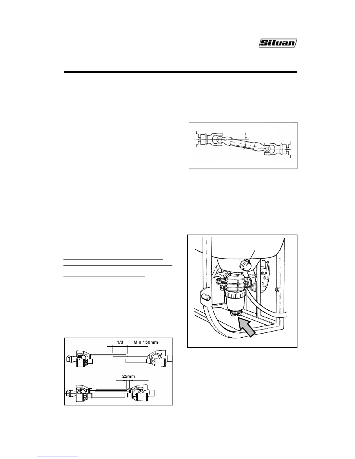
PTO Shaft Length
Note: Upon delivery of a new sprayer it is the
selling dealer’s responsibility to install and set the
PTO shaft to the correct length. The following
information is provided for reference.
Set the linkage height so the ends of the two
drive shafts are at their closest. Install the PTO
shaft making sure there is at least 25mm of
telescopic travel remaining between the male
and female sections. Raise and lower the
sprayer to check that the PTO telescopic tubes
overlap by approximately 1/3rd their length, and
not less than 150mm, in all operating positions.
If the PTO shaft must be shortened cut equal
amounts from both male and female shafts and
safety covers. Carefully remove all burrs then
clean and relubricate before reassembling.
If the operating angles of the PTO shaft exceed
35
0
a constant velocity joint must be fitted by
your Silvan dealer.
Operation
350 Maximum
PTO OPERATING ANGLE
Starting the Sprayer
When starting the sprayer for the first time
conduct a trial run using clean water only (no
chemicals) to become familiar with the operation
of the controls and to check that all systems are
functioning correctly without any leakage.
Before filling the tank ensure that the drain cap is
fitted and the basket strainer is in place and
clean. Close the lid securely after filling.
SHUT OFF VALVE AND SUCTION FILTER
DRAIN CAP
The suction filter is fitted with a shut-off valve which
closes automatically when the valve cap is
screwed off. This allows the filter cover to be
unscrewed and the element to be removed for
cleaning while there is fluid in the tank. Gloves
should be worn when handling the filter.
Page 9
Page 8
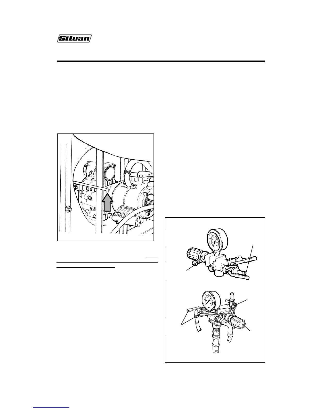
GEARBOX IN ENGAGED POSITION
When the sprayer is operating the valve must be fully
screwed in to open the shut-off valve and allow fluid
to pass through the filter. Directional arrows are
moulded into the valve cap to show the opening and
closing operation.
Check that the oil level in the diaphragm pump is
level with the mark in the viewer and if necessary top
up with SAE 20W-40 multigrade engine oil. When
starting for the first time ensure that the gearbox oil
level is correct and that the PTO has been lubricated
- refer Maintenance section.
Operation
Check that the fan gearbox is engaged. The
selector lever should be in the up position. Never
engage the fan drive with the tractor engine
running or the PTO engaged. Moving the lever to
the down position puts the gearbox into neutral and
the pump will operate without the fan.
Flip the required number of spray nozzles to the
open position, refer to page 10. Refer to the
Calibration section for information on nozzles and
jet selection.
Before engaging the PTO, move the by-pass
control “A” to the by-pass position (clockwise) and
close the outlet valves “C”.
Engage the tractor PTO slowly and allow the
sprayer to run in by-pass mode. Once the pump is
primed increase the tractor speed to
540 PTO rpm.
The by-pass lever can then be moved to the
operating or pressure position (anti-clockwise) and
the pressure can be adjusted by regulator knob “B”
whilst observing the gauge.
Depending upon the type fitted, the pump is
designed to operate up to a maximum pressure
of either 30 Bar (435 psi) or 40 Bar (580 psi).
Refer to the pump identification plate and the
Specifications page for details.
The pressure used for spraying may be varied
between 10 Bar (145 psi) and the pump’s
maximum depending upon the application rate refer to the Calibration section.
Open the outlet valves to commence spraying.
Two and Three Outlet Control Units
The 200 litre Airblast sprayer is fitted with a two
outlet control. The 400 and 500 litre models use
a three outlet control with two outlets connected
to the airblast nozzles whilst the third can be
used to connect a spray gun or other device. The
operation of both control units is the same.
The selection of by-pass or pressure mode is
controlled by the lever “A” - refer diagrams
below. Moving the lever clockwise through its full
travel selects by-pass which reduces the pumps
operating pressure by allowing liquid to bypass
the pressure regulator. Note, this operation does
not fully shut off the flow to the individual outlet
taps. Moving the lever full anti-clockwise, redirects pressurised fluid to the outlets.
Pressure
regulator
“B”
PRE
SSU
RE CONTROLUNIT
S
TWO OUTLET USED WITH MP-40 PUMP
Outlet
valves
“C”
By-pass
control
“A”
Pressure
regulator
“B”
Outlet
valves
“C”
By-pass
control
“A”
THREE OUTLET WITH APS-71 AND APS-96 PUMPS
Page 10
Page 9
Operation
System pressure is regulated by turning knob “B” and
observing the reading on the gauge. Turning the
knob clockwise increases the pressure and turning
anti-clockwise decreases pressure.
Fluid is directed to the airblast nozzles by outlet
valves “C” which are open when the lever is in line
with the direction of flow and closed when across the
direction of flow. The valves may be operated
individually to direct spray to either side or as a pair
to spray simultaneously from both sides .
If you wish to stop spraying but leave the tractor PTO
running, close the outlet valves “C” and move the bypass lever “A” to by-pass mode.
For spraying applications using only the third outlet,
on those models fitted with three outlet valves, the
fan can be disengaged to reduce unnecessary wear
and fuel consumption.
Flip On/Off Nozzles
Warning ! Relieve pressure in spray lines before
turning nozzles on.
The flip on/off nozzles incorporate an off position to
allow individual jets to be turned off when not
needed. The jets can be positioned by loosening the
attaching locknut and aligning the outlet to the
required angle. These two features enable the spray
pattern to be regulated to achieve the required
coverage without wastage of chemicals.
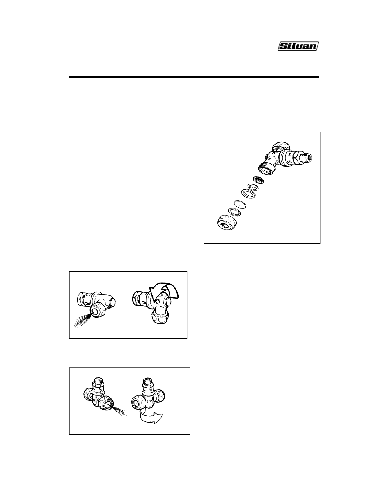
The nozzles fitted to 200 litre sprayers have a
single outlet which is turned on or off by rotating
the nozzle through 90
0
.
DOUBLE OUTLET NOZZLE
SINGLE OUTLET NOZZLE
The nozzles fitted to 400 and 500 litre sprayers
have two outlet jets, one at each end of the
nozzle, but only the jet which is flipped to the
outward facing position is “on”. This facilitates
convenient changing between jets of different
sizes, for example, when requiring application
rates to suit concentrate and dilute
spraying.
NOZZLE ASSEMBLY
CERAMIC JET
Both types of nozzle incorporate ceramic jets,
stainless steel swirl plates and stainless steel
mesh strainers, separated by neoprene gaskets.
The purpose of the swirl plate is to create a
conical spray pattern. Nozzle output at a
particular spray pressure can be varied by fitting
different combinations of jet and swirl plate as
shown in the Nozzle Output Chart on page 13.
Ceramic jets are sized according to the diameter
of the central hole in millimetres.
Swirl plates can either have a closed centre,
identified as CC, or a central hole which is sized
in millimetres. Closed centre swirl plates produce
a hollow cone spray pattern and are fitted for low
outputs. At higher outputs, swirl plates with a
central hole are necessary to fill the centre of the
conical spray pattern.
Ceramic jets and swirl plates normally have a
long wear life and require little maintenance other
than regular checking and cleaning of strainers.
The spray pattern should be observed
periodically against a dark background to detect
signs of wear which will be indicated by
a streaky
or broken pattern. If worn jets are detected then
the full set of jets, swirl plates and gaskets
should be replaced.
Page 11

Page 10
Nozzle Selection and Calibration
Nozzle Selection and Calibration Checking
Chemical application rates and hence nozzle
selections will vary greatly depending on the crop
type, stage of crop development and the regional
area. Information on application rates should be
available from your chemical supplier or State
Department of Agriculture.
Nozzle selection can be made by following the four
simple steps shown below. The fourth step,
checking the calibration after nozzle selection,
improves efficiency by ensuring a known amount of
spray is applied per hectare.
STEP 1 Operating Factors
First establish the following factors.
a) Application rate (l/ha) in litres per hectare.
b) Speed (km/hr) The travel speed indicated by
your tractor can be checked by timing the sprayer
over a measured distance. The timing should be
done in seconds over 100 metres with the PTO
engaged and water in the tank to simulate real
spraying conditions. In hilly terrain the sprayer
should be timed driving up and down the hill and
the two times averaged. The speed can be
calculated according to the following formula.
Speed (km/hr)=
360
Time in seconds for 100
c) Row width (m)
The distance between rows measured in metres.
d) Spray pressure (Bar) A spray pressure of
between 20 and 30 bar is usually selected. Lower
spray pressures will produce larger droplets which
are generally less effective than smaller droplets
produced at higher pressures.
STEP 2 Total Output Required
Calculate the total spray output required in litres
per minute (l/min) using the following formula.
Total output (l/min) =
Application rate (l/ha) x Speed (km/hr) x Row width (m)
600
Check that the calculated output does not exceed
the rated capacity of the pump. If it does, reduce
the travel speed or the application rate.
STEP 3 Nozzle Selection
a) Nozzle sets to suit a variety of applications can
be selected directly from the Jet/Swirl Plate
Combination charts on the following pages.
b) For other applications or those not requiring all
jets to be used, such as vineyards, the correct
nozzles can be selected by calculating the nozzle
requirements for one side of the sprayer then
copying the selected nozzles on the other side of
the sprayer.
Decide on the number of nozzles to be used on
one side and the percentage of spray required from
each (the total should be 100%).
To obtain the individual nozzle flow rates, halve the
total output calculated at Step 2, to obtain the total
output for one side, and multiply it by the
percentage output required from each nozzle.
Use the Nozzle Output Chart on the following page
to select the nozzle and swirl plate combination
which will give the required nozzle output at the
spraying pressure you have chosen.
Output per side (l/min) = Total output (l/min)
2
Nozzle output (l/min) =
Nozzle percentage (%) x Output per side
(l/min)
100
Add up the flow rates of the individual jets to check
that the total output per side matches the
calculated value. Small variations can be corrected
by increasing pressure to increase output or
reducing pressure to reduce output.
STEP 4 Calibration Checking
After installing the selected jets, test the sprayer
with water to confirm the application rate.
Fill the tank to the brim or a specific mark then run
the sprayer for a measured time at be sufficient
.
operating pressure and with nozzles spraying. A
run time of 2 minutes should
Measure the volume of water, in litres, required to
refill the sprayer to the brim or the specific mark
chosen then divide this volume by the time of the
test run, in minutes.
Output (l/min) = Volume to refill (litres)
Time (min)
Verify that the measured output matches the value
calculated at Step 2. For small variations increase
the spraying pressure to increase the output or
reduce the pressure to reduce output.
A nozzle selection example and worksheets to
record calibration results are shown on
pag
e 14.
Page 12
Page 11
When to Spray
Results will be best when the wind speed is low, temperature is low and relative humidity high. An ideal
time is at sun up when these conditions are most likely to apply.
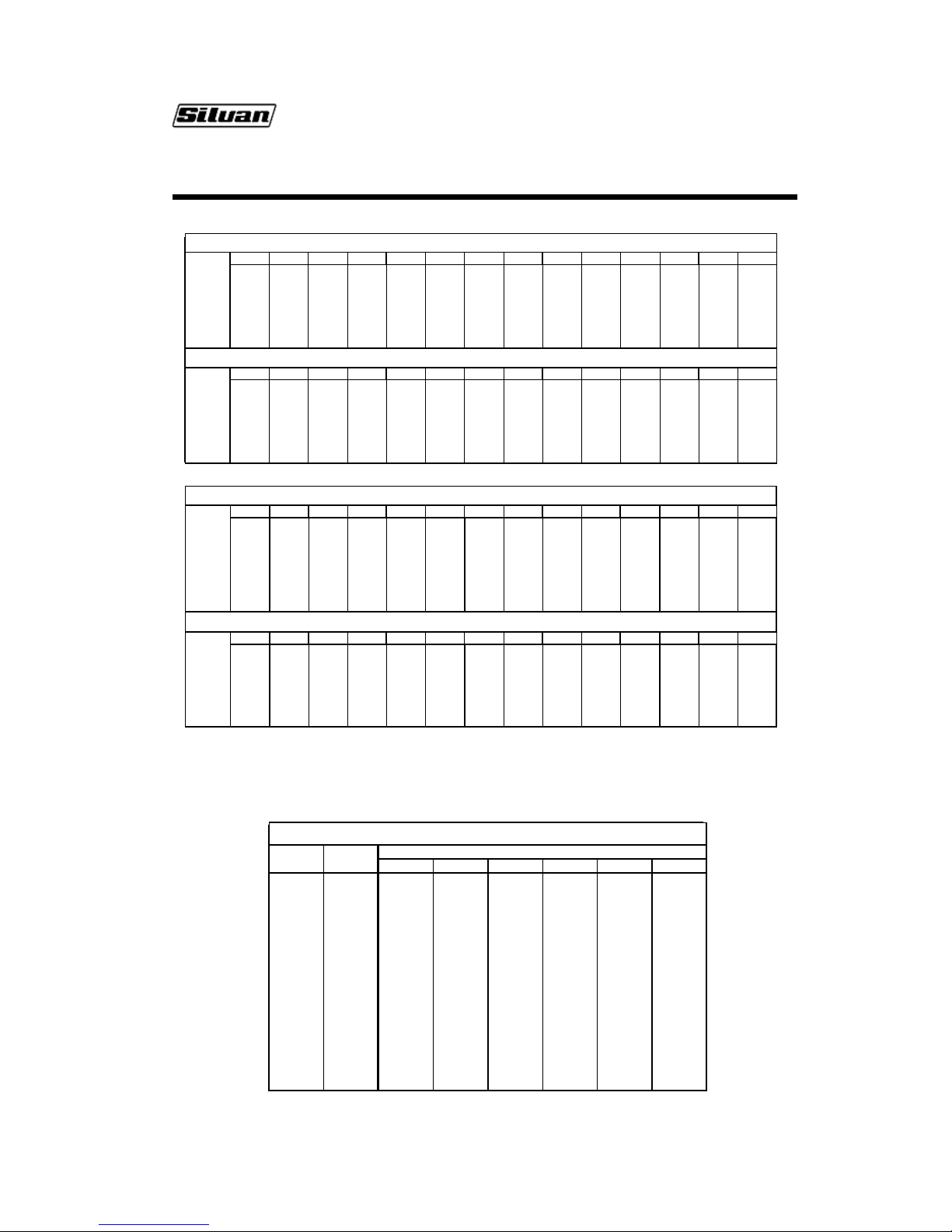
Jet/Swirl Plate Combination Charts
The following Jet/Swirl Plate Combination Charts show the total sprayer output that can be achieved from
each of the three Suntuff Linkage Airblast models at various operating pressures using different sets of
jets and swirl plates, e.g. 0.8/CC indicates a 0.8mm jet combined with a Closed Centre swirl plate.
Each of the jet/swirl plate sets is a typical combination that will be suitable for a number of spraying
applications. Use of these charts eliminates the need to calculate the output from individual nozzles.
Ensure that the chart used is the one which is applicable to your sprayer model.
Nozzle Selection and Calibration
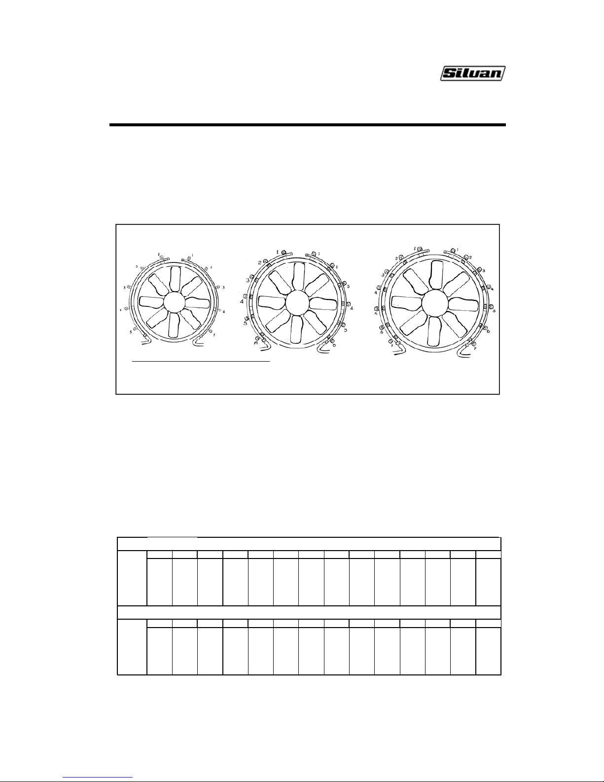
Spray Bar Nozzle Positions
The Spraybar Nozzle Positions for each of the three Suntuff Linkage Airblast models shown in the
diagrams below correspond to those in the Jet/Swirl Plate Combination Charts .
200 LITRE
600 MM FAN
5 NOZZLES PER SIDE
400 LITRE
700 MM FAN
6 NOZZLES PER SIDE
500 LITRE
800 MM FAN
7 NOZZLES PER SIDE
SPRAY BAR NOZZLE
CHART NO. 1 - JET / SWIRL PLATE COMBINATIONS - FOR 200 LITRE AIRBLAST SPRAYER WITH 5 JET SPRAYBAR
NOZZLE AB005 AB015 AB025 AB035 AB045 AB055 AB065 AB075 AB085 AB095 AB105 AB115 AB125 AB135
POSITION
1
0.8/ CC 1. 0/CC - - - 1. 0/CC 1.2/ CC - 1. 2/CC - 1.5/ CC - 1. 2/CC 1.8/ CC
2
0.8/ CC 1. 0/CC 1.2/ CC 1. 5/CC 1.8/ CC 1. 5/CC 1.2/ CC 1. 5/CC 1.5/ CC 2. 0/CC 1.5/ CC 1.8/CC 1.8/ CC 1.8/CC
3
0.8/ CC 1. 0/CC 1.2/ CC 1. 5/CC 1.8/ CC 1. 5/CC 1.2/ CC 1. 5/CC 1.5/ CC 2. 0/CC 1.5/ CC 1.8/CC 1.8/ CC 1.8/CC
4
0.8/ CC 1. 0/CC 1.2/ CC 1. 5/CC 1.8/ CC 1. 2/CC 1.2/ CC 1. 5/CC 1.2/ CC 2. 0/CC 1.5/ CC 1.8/CC 1.5/ CC 1.8/CC
5
0.8/ CC 1. 0/CC 1.2/ CC - - 1. 0/CC 1.2/ CC 1. 5/CC 1.0/ CC - 1.5/CC 1.8/CC 1.5/ CC 1. 8/CC
TOTAL SPRAYER OUTPUT (BOTH SIDES) - IN LITRES PER MINUTE
PRESSURE AB005 AB015 AB025 AB035 AB045 AB055 AB065 AB075 AB085 AB095 AB105 AB115 AB125 AB135
(BAR)
10
9 13141416181718192023222327
15
10 15 16 16 19 21 20 22 22 23 27 26 28 32
20
12 17 18 19 22 25 23 25 25 26 31 29 31 36
25
13 19 21 20 25 26 26 26 27 28 33 33 35 41
30
14 21 22 22 27 28 28 29 29 31 36 36 38 45
Page 13
Page 12
Nozzle Output Chart
The Nozzle Output Chart below shows the output from a single nozzle for the full range of jet and swirl
plate combinations, at various spraying pressures. It can be used to calculate nozzle selections for
situations which are not covered by one of the Sets shown in the Jet/Swirl Plate Combination Charts.
Nozzle Selection and Calibration
CHART NO. 2 - JET / SW IRL PLATE COMBINATIONS - FOR 400 & 500 LITRE AIRBLAST SPRAYER WITH 6 JET SPRAYBAR
NOZZLE AB006 AB016 AB026 AB036 AB046 AB056 AB 066 AB076 AB086 AB096 AB106 AB116 AB126 AB136
POSITION
1
- 0. 8/CC 1. 0/CC - 1.0/1.0 1. 2/CC 1. 2/CC - - - 1. 5/CC 1.2/1. 0 1. 0/1.0 -
2
0.8/CC 0. 8/CC 1. 0/CC 1.0/1. 0 1. 0/1.0 1.2/CC 1.5/ CC 1. 5/1.2 1.5/ 1.2 1.5/1. 2 1. 8/1.5 1.5/ 1.2 2.0/1. 8 2. 0/1.8
3
0.8/CC 0. 8/CC 1. 0/CC 1.0/1. 0 1. 0/1.0 1.2/CC 1.5/ CC 1. 5/1.2 1.5/ 1.2 1.5/1. 2 1. 8/1.5 1.5/ 1.2 2.0/1. 8 2. 0/1.8
4
0.8/CC 0. 8/CC 1. 0/CC 1.0/1. 0 1. 0/1.0 1.2/CC 1.5/ CC 1. 2/1.0 1.5/ 1.2 1.5/1. 2 2.0/ CC 1. 5/1.2 1.0/ 1.0 2. 5/CC
5
0.8/CC 0. 8/CC 1. 0/CC 1.0/1. 0 1. 0/1.0 1.2/CC 1.2/ CC 1. 2/1.0 1.2/ 1.0 1.5/1. 2 1.2/ CC 1. 2/1.0 1.0/ 1.0 1. 0/CC
6
- 0. 8/CC 1. 0/CC 1.0/1. 0 1. 0/1.0 1.2/CC 1.0/ CC - - - 0. 8/CC 1.0/1. 0 0.8/ CC 0.8/ CC
TOTAL SPRAYER OUTPUT (BOTH SIDES) - IN LITRES PER MINUTE
PRESSUR E AB006 AB 016 AB026 AB036 AB046 AB056 AB066 AB076 AB086 AB096 AB106 AB116 AB126 AB136
(BAR)
10
7.2 10.8 15.6 16. 0 19.2 20.4 23.2 24. 4 26.6 28.8 33. 2 34.8 36.2 37.0
15
8.0 12.0 18.0 19. 0 22.8 24.0 27.2 28. 8 31.2 33.6 39. 0 41.0 44.6 45.6
20
9.6 14.4 20.4 22. 0 26.4 27.6 31.2 32. 8 35.6 38.4 44. 6 46.8 50.4 51.4
25
10.4 15. 6 22.8 24.0 28.8 31.2 34.0 36. 4 39.4 42.4 49. 2 51.8 55.4 56.8
30
11.2 16. 8 25.2 26.0 31.2 33.6 37.0 39. 6 43.0 46.4 53. 2 56.4 60.0 61.8
40
12.8 19. 2 28.8 30.0 36.0 38.4 41.6 46. 4 50.8 55.2 62. 0 66.2 68.4 70.6
CHART NO. 3 - JET / SWI RL PL ATE COMBI NATI ONS - FO R 500 LI TRE AIRBLAS T S PRAYER WI TH 7JET S PRAYBAR
NOZZLE AB0 07 AB0 17 AB02 7 AB03 7 AB047 AB0 57 AB0 67 AB07 7 AB08 7 AB097 AB1 07 AB1 17 AB12 7 AB13 7
POSITION
1
----------1.2/CC-1.2/1.0-
2
- - - 0.8/CC - - - - 1.0/1.0 - 1. 5/CC 1.2/ 1.0 1.5/1. 2 1.5/ 1.2
3
0.8/CC 0. 8/CC 1. 0/1.0 0.8/ CC 1.0/CC 1. 0/1.0 1.2/CC 1. 2/1.0 1.0/ 1.0 1.2/ 1.0 1.5/CC 1. 2/1.0 1.5/1. 2 1. 5/1. 2
4
0.8/CC 0. 8/CC 1. 0/1.0 0.8/ CC 1.2/1. 0 1.0/ 1.0 1. 5/CC 1.2/ 1.0 1.0/1. 0 1.2/1. 0 1. 5/CC 1. 2/1.0 1.5/1. 2 1. 5/1. 2
5
0.8/CC 0. 8/CC 1. 0/1.0 0.8/ CC 1.2/1. 0 1.0/ 1.0 1. 5/CC 1.2/ 1.0 1.0/1. 0 1.2/1. 0 1. 2/CC 1. 2/1.0 1.2/1. 0 1. 5/1. 2
6
- 0.8/CC - 0.8/ CC 1.0/CC 1. 0/1.0 1.0/CC - 1.0/1.0 1. 2/1.0 1.0/CC 1. 2/1.0 1.0/1. 0 1. 5/1. 2
7
- - - 0.8/CC - - - - 1.0/1.0 - 1. 0/CC 1.2/ 1.0 1.0/1. 0 1.5/ 1.2
TOTAL SPRAYER OUTPUT (BOTH SIDES) - IN LITRES PER MINUTE
PRESS URE AB007 AB0 17 AB0 27 AB03 7 AB04 7 AB057 AB0 67 AB0 77 AB08 7 AB09 7 AB107 AB11 7 AB127 AB1 37
(BAR)
10
5.2 7. 0 9. 5 10.4 12.0 12. 6 15.0 15. 0 19.0 20.0 25.5 30. 0 37.9 43.2
15
6.2 8. 2 11.3 12.4 14. 0 15.1 17.5 18.1 22.7 24. 2 30.1 36.2 44.8 50.4
20
7.2 9. 6 13.0 14.4 16. 0 17.3 20.2 20.6 25.9 27. 5 34.3 41.3 51.2 57.6
25
7.9 10.5 14. 2 15.7 17.8 19.0 22. 2 22.5 28.4 30.0 37.8 45. 0 56. 0 63.0
30
8.5 11.4 15. 4 17.0 19.7 20.5 24. 2 24.3 30.7 32.4 41.3 48. 6 60. 1 69.0
40
9.8 13.1 17. 9 19.7 22.6 23.8 27. 3 28.1 35.8 37.4 46.6 56. 2 71. 7 82.2
NOZZLE OUTPUT CHART
JET SW IRL SINGLE NOZZLE OUTPUT - IN LITRES P ER M INUTE
SIZE PLATE
10 Bar 15 Bar 20 Bar 25 Bar 30 Bar 40 Bar
0.8 CC 0.9 1.0 1.2 1.3 1. 4 1.6
1.0 CC 1.3 1.5 1.7 1.9 2. 1 2.4
1.2 CC 1.7 2.0 2.3 2.6 2. 8 3.2
1.5 CC 2.3 2.7 3.1 3.3 3. 6 4.0
1.8 CC 2.7 3.2 3.6 4.1 4. 5 5.0
2.0 CC 3.4 3.8 4.3 4.7 5. 1 5.7
2.2 CC 3.8 4.1 4.6 5.1 5. 6 6.6
2.5 CC 3.9 4.7 5.4 6.0 6. 6 7.7
1.0 1.0 1. 6 1.9 2. 2 2.4 2.6 3.0
1.2 1.0 2. 5 3.0 3. 4 3.8 4.1 4.7
1.5 1.2 3. 6 4.2 4. 8 5.3 5.8 6.9
1.8 1.5 5. 0 5.9 6. 7 7.4 8.0 9.5
2.0 1.8 6. 2 7.8 8. 7 9.6 10.4 11. 8
2.2 2.0 7. 8 8.7 9. 9 11.2 12.5 14.3
2.5 2.2 8. 8 10.5 12. 1 13.5 14.7 16.2
Page 14
Page 13
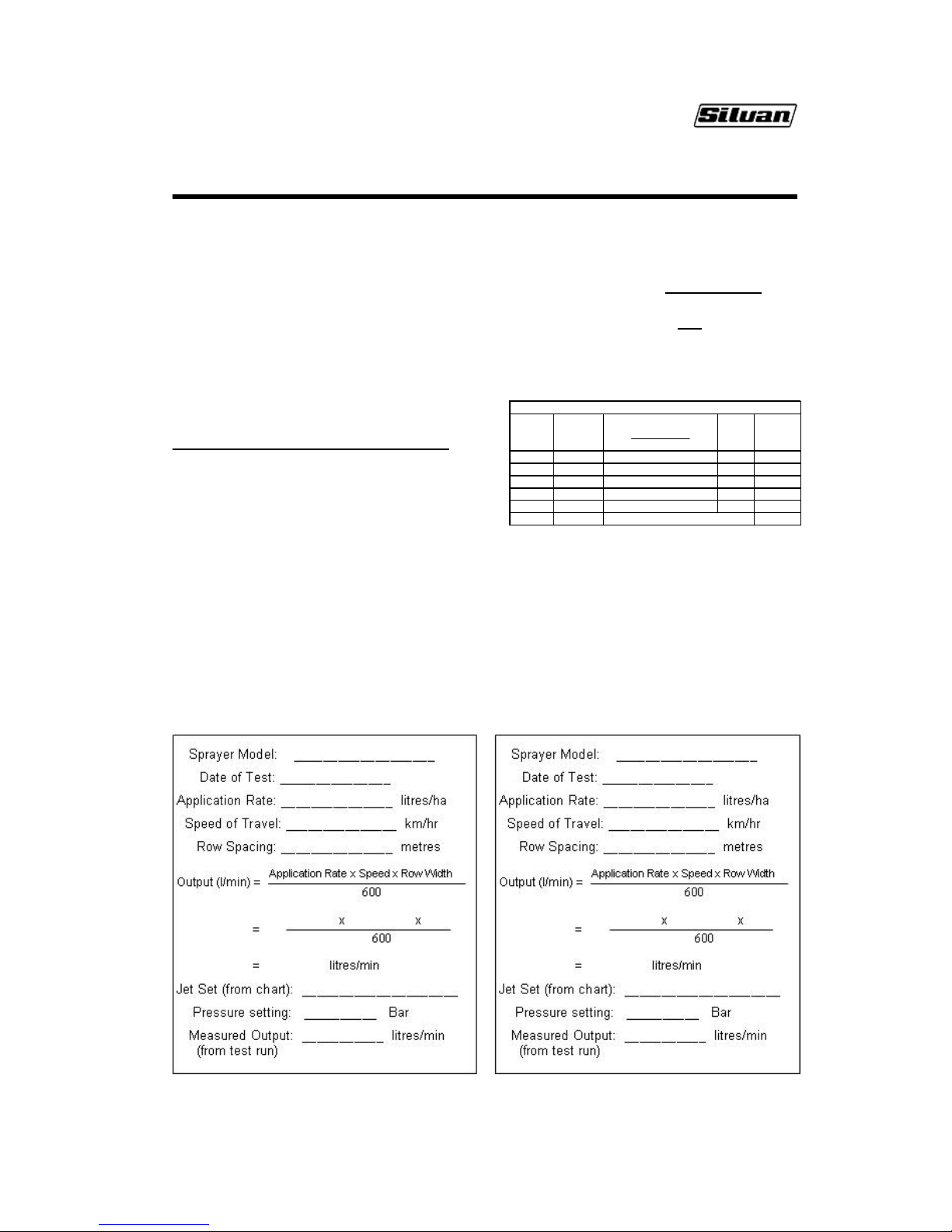
Calibration Worksheets
The two worksheets below can be used to record the results of calibration tests on your sprayer.
Calibration and Nozzle Selection
Nozzle Selection Example
This example applies to a 200 litre model with 5
nozzles per side but the same procedure can be
used for the larger models by allowing for the
additional nozzles in the calculation 3b).
STEP 1
a) Required application rate = 800 l/ha
b) Chosen speed = 5 km/hr
c) Row width = 3 m
d) Spray pressure = 25 Bar
STEP 2
Total spray output needed (l/min) =
Application Rate(l/ha) x Speed (km/h) x Row width(m)
600
=
800x5x3 = 20 l/min
600
STEP 3
a) For a standard application on a 200 litre
unit using 5 nozzles per side, with each giving an
equal discharge, refer to Chart No. 1 on the
previous page.
The chart shows Nozzle Set 2 (1.0 mm jets and CC
swirl plates in all nozzles) will give 19 l/min at 25
Bar. Install this Set and spray at a little over 25 Bar
to achieve the 20 l/min required.
For 400 or 500 litre sprayer models refer to Charts
No. 2 and No. 3, respectively.
b) For non standard applications calculate the
flow required for each nozzle then consult the
Nozzle Output Chart on the page 13 to select the
jet and swirl plate to install in each nozzle.
Output per side (l/min) = Total output (l/min)
2
= 20 = 10 l/min
2
If for example, 12.5% of the flow is required from
the top and bottom nozzles and 25% from the
others, make the calculations in the table below.
NOZZLE SELECTION CALCULATION
Nozzle No.
from top
% Flow
each nozzl e
Desired Nozzle Output (l/min)
= Flow per side x %
100
Jet/ Swirl
Siz e
Flow Rate
(l/min)
from Chart
112
.
5 10 x 12.5/100 = 1.25 0.8/CC 1.3
2 25 10 x 25/100 = 2.5 1.2/CC 2.6
3 25 = 2.51
.
2/CC 2.6
4 25 = 2.51
.
2/CC 2.6
512
.
5 = 1.25 0.8/CC 1.3
Total 100 Total Flow per Side (l/min) 10.4
Fit 0.8/CC jets/swirl plates in nozzles 1 and 5 and
1.2/CC in nozzles 2, 3 & 4. Use a little under 25
Bar to reduce the output to 10 l/min per side.
STEP 4
Fill the tank with water to a mark. Run for 2
minutes at 540 PTO rpm and a little under 25 Bar
with all nozzles operating. Measure the
volume to refill to the mark. This should be very
close to 40 litres if calibration is correct.
Page 15
Page 14
Optional Equipment
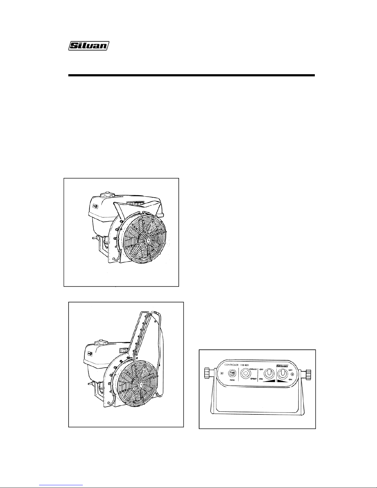
Two Side Conveyor
The two side conveyor controls the shape of the
airblast to produce a horizontal discharge from
each side of the sprayer for efficient coverage of
vines or crops of similar height. It is normally
ordered as a factory fitted option and is available
for all three Suntuff Linkage Airblast models. Once
installed no adjustment is necessary. Depending
upon the sprayer model and number of nozzles
fitted, it may be desirable to turn off the upper
nozzle on each spray bar to achieve the best spray
pattern.
Single Side Conveyor
The single side conveyor controls the shape of
the airblast to produce a high discharge pattern
from the left side of the sprayer for efficient
coverage of tree crops. It is normally ordered as
a factory fitted option and is available for all
models. The right hand spray bar is relocated
into the upper section of the conveyor outlet, as
shown in the diagram, and the unit incorporates
an adjustable vane which can be used to
regulate the height of discharge.
Electric Cabin Controls
The electric control system enables spraying to
be stopped and started and the output to be
directed to the left, right or both spraybars from
the tractor cabin whilst on the move. It is
available as a factory fitted option and can be
supplied on all Linkage Airblast models.
A 7 pin cable socket enables the control box to
be permanently installed in the tractor cabin and
allows the wiring to the sprayer to be easily
connected or disconnected.
Spraying pressure is first adjusted manually at
the pressure regulator and the sprayer can then
be switched between “spray” and “by-pass”
modes whilst on the move, by using the switch
on the cabin control box. This activates a
solenoid valve at the pressure regulator to
direct
fluid to the spraybars or by-pass it to the tank.
Fluid can be directed to the left or right spraybar,
or both simultaneously, by setting either or both
of the two toggle switches on the control box to
the “on” position. These operate solenoid valves
on the spraybars. Once selected, the output
mode can be maintained by using the “spray or
by-pass” switch to start and stop spraying.
Full instructions for fitting the control box and
operating the system are given in the
Operators
Manual supplied with the unit.
TWO SIDE CONVEYOR
SINGLE SIDE CONVEYOR
Page 16

Page 15
Trouble Shooting
Pump does not prime
x No liquid in tank or not covering suction inlet .
x Suction filter blocked.
x Suction filter stop valve closed.
x Suction filter bowl loose or missing O-ring.
x Suction line loose allowing pump to suck air.
x Bypass control not in by-pass position.
x Pump valve springs broken or valves worn.
Pump does not reach correct pressure
x Pump not operating at full 540 rpm.
x Suction filter blocked.
x Suction filter stop valve partly closed
x Pressure regulator not correctly adjusted
x Pressure regulator valve and seats worn.
x Pressure gauge faulty
x Pump diaphragms ruptured (pump oil grey).
x Worn nozzles or capacity of nozzles greater
than capacity of the pump.
Fan noisy and/or vibrating
x Gearbox bearings worn.
x Fan damaged or out of balance.
x PTO incorrectly installed.
x PTO geometry not correct.
Driveshaft noisy
x PTO shaft not secured properly to shafts.
x Universal joint crosses worn.
x PTO geometry not correct.
Airblast reduced
x Fan mesh blocked with leaves or debris.
x Not operating at full speed of 540 rpm.
x Fan gearbox not in gear.
Poor tank agitation
x Chemical left in tank whilst not operating.
x Chemical insufficiently mixed before filling.
Pump and hoses vibrating.
x Pump surge chamber pressure incorrectly
adjusted or surge diaphragm ruptured.
x Air entering the suction line through loose or
damaged fittings.
x Pump valves or valve springs worn or
damaged.
x Worn nozzles or nozzles to big for the
capacity of the pump.
x Air trapped in filter or suction lines.
Page 17
Page 16
Spraying (Bar)
p
ressure (psi)
2 - 5
29 - 73
5 - 10
73 - 145
10 - 20
145 - 290
20 - 50
290
Surge air (Bar)
pressure (psi)
2
29
2 - 5
29 - 73
5 - 7
73 - 1027102
Spraying (Bar)
pressure (psi)
2 - 5
29 - 73
5 - 10
73 - 145
10 - 20
145 - 290
20 - 50
290
Surge air (Bar)
pressure (psi) 229
2 - 5
29 - 73
5 - 7
73 - 102 7102
Lubrication and Maintenance
Daily Maintenance
General
During the first few days of operation, before
starting each day check that all hardware is tight
and tighten all hose clamps. Inspect the unit for
leaks while running .
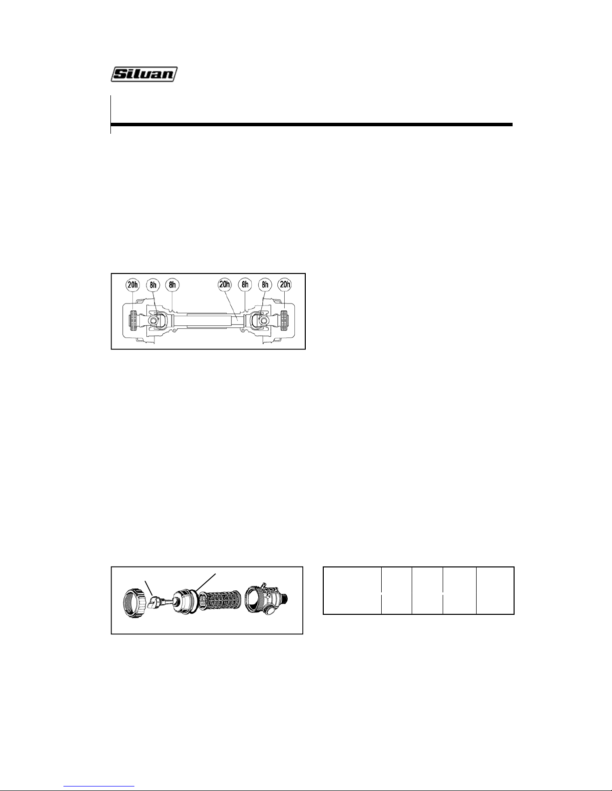
PTO Shaft
Grease the PTO shaft with multi-purpose grease at
the time intervals shown below. This is the amount
of lubrication recommended for normal operation.
More frequent inspection and lubrication may be
needed under very dusty conditions
.
Pump
Check the oil level in the viewer daily and if
necessary top up with SAE 20W-40 multigrade
engine oil. The oil must reach the mark on the side
of the oil level viewer.
Filters
Clean all filters as stated below. More frequent
cleaning may be found necessary depending upon
circumstances. The best method for cleaning filters
is to wash them with a soft bristle brush. Check for
any tears or holes and replace if damaged.
Check and if necessary clean the basket strainer
under the tank lid before each fill.
Always clean the suction filter before each tank
refill and at the end of the day. Close the stop valve
by pushing and nscrewing the yellow tap, then
unscrew the filter cover to remove the element.
Ensure the O-ring is in good condition when
refittin
g
.
Tank, Pump and Spray Lines
At the end of each day run clean water through the
pump and lines to purge them of chemicals.
Rinse out the tank to remove powdered material.
Never leave chemicals in the tank that may settle
to the bottom, harden and break into lumps as this
may block the suction filter.
Dispose of unused chemical, chemical mix, rinse
water and chemical containers as recommended
by the chemical manufacturer or appropriate
government authority.
Weekly Maintenance
PTO Shaft (Every 20 Hrs) Slide the PTO shaft
apart, clean the telescopic tubes with kerosene and
apply multi-purpose grease to the sliding surfaces,
then reassemble.
This is most important in dusty conditions.
Monthly Maintenance
Gearbox Check the oil level every 50 hours and if
required top up with SAE 80W-90 gear oil.
The oil should be level with the centre of the input
shaft and can be checked through the filler plug in
the top of the gearbox using a piece of wire as a
dip stick.
Annual Maintenance
Diaphragm Pump Drain the oil from the pump
annually, or at the end of each spraying season.
Remove the pump heads, carefully inspect the
diaphragms and replace if necessary. Also check
the inlet and outlet valves, seats and springs for
wear, damage or chemical corrosion and replace
as necessary. Refill with SAE 20W-40 multi-grade
engine oil.
Check the air pressure in the surge chamber at the
end of the pump. The air pressure behind the
chamber’s diaphragm smooths out the pulsations
in fluid flow and should be set in accordance with
the spraying pressure being used - refer chart
below. Adjust the pressure at the valve fitting on
the chamber using using a compressed air hose
fitted with a tire valve connection and a reliable
pressure gauge.
Refer to the pump instruction manual for further
details on the above maintenance operations.
Hardware
At the end of each season generally inspect the
sprayer for any signs of damage and check that all
bolts are securely tightened.
O-Ring
SUCTION FILTER COMPONENTS
Stop Valve Ta
p
Page 18
SILVAN AUSTRALIA PTY. LTD.
ABN 48 099 851 144
89 Lewis Road,
Wantirna South 3152
Australia
Telephone: +61 (03) 9887 2788
Facsimilie: +61 (03) 9887 1035
www.silvanaust.com
 Loading...