

Silicon Valley Computer SHUGART 706, SHUGART 712 Reference Manual
...•..
~
..:,.,..'
...
~
~
REFERENCE
MANUAL
SHUGART
706/712
HARD
DISK
Silicon
Valley
Computer
.'.
( 40 8) 28 8- 88 37
.I
-
~
-
~
-
"
-
~
-
.~
-
~
-
,~
-
~
:
.~
-
-,
i
••
'.
:
~
..
..
.
•
••
·
~
•
•
..
j
..
~.
-
..
I!I
..
-.
.
.
'.
•
'f8
,
t
TABLE OF CONTENTS
Page
TABLE
OF
CO~S
. . . . . . . . . . . . . . . . . . . . . . . . . . . . . . . . . . . . . . . . . . .
ill
UST
OF
AGURES
vi
UST
OF
TABLES
vii
ABBREVlA
llONS/MNEMONlCS
viii
NOTICE
TO
USERS
viii
PRODUCTION
DESCRIPTION
SECTION
I
~ODUCT10N
1:1
1.1
Purpose..........................................................
I-I
1.2 General
Description
. . . . . . . . . . . . . . . . . . . . . . . . . . . . . . . . . . . . . . . . . . . . . . . .
..
1·1
1.3
Specifications
Summmy . . . . . . . . . . . . . . . . . . . . . . . . . . . . . . . . . . . . . . . . . . . . .
..
1-2
1.3.1
Perfonnanc~
Specifications. . . . . . . . . . . . . . . . . . . . . . . . . . . . . . . . . . . . .
..
1-2
1.3.2
Functional
Specifications. . . . . . . . . . . . . . . . . . . . . . . . . . . . . . . . . . . . . . .
..
1-2
1.3.3
Physical
Specifications
. . . . . . . . . . . . . . . . . . . . . . . . . . . . . . . . . . .
..
1-2
1.3.4
Reliabtlrty
Specifications
. . . . . . . . .
..
1-3
1.4
Functional
Characteristics . . . . . . . . . . . . . . . . . . . . . . . . . . . . . . . . . . . . . . . . . . . .
..
1·3
1.4.1
General
Operation . . . . . . . . . . . . . . . . . . . . . . . . . . . . . . . . . . . . . . . . . . .
..
1·3
1.4.2
Read/Write
and
Control Electronics 1-4
1.4.3
Drive
Mechanism. . . . . . . . . . . . . . . . . . . . . . . . . . . . . . . . . . . . . . . . . . . .
..
1-4
1.4.4
Positioning
Mechanism.
. . . . . . . . . . . . . . . . . . . . . . . . . . . . . . . . . . . . . . .
..
1-4
1.4.5
R~d/Write'Heads
and
Disk(s)
'
'.
. . . .
..
1-4
1.4.6
A1r
Altration
System.
. . . . . . . . . . . . . . . . . . . . . . . . . . . . . . . . . . . . . . . . .
..
1-4
1.4.7
Spindle Lock and
Brake.
. . . . . . . . . . . . . . . . . . . . . . . . . . . . . . . . . . . . . .
..
1-6
1.4.8
R~d/Write
Head
Shipping
Zone.
. . . . . . . . . . . . . . . . . . . . . . . . . . . . . . .
..
1-6
1.5 Functional Operations . . . . . . . . . . . . . . . . . . . . . . . .
..
1-6
1.5.1
Power
Sequendng
1-6
1.5.2
Drive
Selection
1-6
1.5.3
Track
Accessing. . . . . . . . . . . . . . . . . . . . . . . . . . . . . . . . . . . . . . . . . . . . .
..
1-7
1.5.4
Read
Operation. . . . . . . . . . . . . . . . . . . . . . . . . . . . . . . . . . . . . . . . . . . . .
..
1-8
1.5.5
Write
Operation. . . . . . . . . . . . . . . . . . . . . . . . . . . . . . . . . . . . . . . . . . . . .
..
1-8
1.5.6 Head
Selection
1·8
SECTION
n
ElECI'R.lCAL
OOERFACE
. . . . . . . . . . . . . . . . . . . . . . . . . . . . . . . . . . . . . . . . . . . . . .
..
2-1
2.1 Introduction
2-1
2.2
Control
Input
Unes
2-2
2.2.1
Drive
Select
1-4.
. . . . . . . . . . . . . . . . . . . . . . . . . . . . . . . . . . . . . . . . . . .
..
2-4
2.2.2
Direction
In
. . . . . . . . . . . . . . . . . . . . . . . . . . . . . . . . . . . . . . . . . . . . . . . .
..
2-4
2.2.3
Step.......................................................
2-4
2.2.4
Head
Select
~
and
2'
. . . . . . . . . . . . . . . . . . . . . . . . . . . . . . . . . . . . . . . . .
..
2-5
2.2.5
Write
Gate. . . . . . . . . . . . . . . . . . . . . . . . . . . . . . . . . . . . . . . . . . . . . . . . .
..
2-6
2.2.6
Reduced Write Current and Precompensation
2-6
2.3
Control
O\Jtput
Unes
. . . . . . . . . . . . . . . . . . . . . . . . . . . . . . . . . . . . . . . . . . . . . . .
..
2-6
2.3.1
Tr&ek
00 . . . . . . . . . . . . . . . . . . . . . . . . . . . . . . . . . . . . . . . . . . . . . . . . . .
..
2-6
2.3.2
Index......................................................
2-6
2.3.3
Ready......................................................
2-6
Ul
TABLE OF CONTENTS (CONT.)
2.3.4
Wrtte Fault .
2.3.5
Seek
Complete
· · · · · · · · · · · · · ·
..
· . · · · . · · · · · · .
2.4
Data Transfer
Unes
·
..
· . · · · · . ·
..
· · · . ·
..
· ·
2.4.1
~
Write
Data .
2.4.2
~
Read
Data .
2.5
Select Status · · · · · · · · . · · · ·
2.6
GeneralTiming
ReqUirements
.................•.....••••..•............
2.7
Power Interface · · . · . · · · · · . ·
2.8
Frame Grounding · · · · · · · · · · · · · . · . ·
SECTION III PHYSICALINTERFACE .
3.1
Introduction .
3.2
Jl!Pl
Connection · · . · · ·
..
· · · · · . · ·
3.3
J5/P5
Connection · · . · · . ·
..
· ·
3.4
J6/P6
Connection · ·
..
· · · · · ·
..
· · · · · · · · · ·
SECTION
IV
PHYSICAL
SPECIACAll0NS
.
4.1
Mechanical
Dimensions
· ' · . · · · · ·
4.2
Mounting .
SECTION
V
MEDlA DEFECTS
AND
ERRORS .
5.1
Error Mapping
and
Qualification .
5.1.1
Cause.s
of
Errors
.
5.1.2
Error Definition
.................................•.............
5.1.3 Media
Defed
Definition .
5.1.4
Error Map .
5.1.5 User
Error
Mapping .
5.2
Error Acceptance
Criteria .
5.3
System Generated
Errors .
SECTION VI RECORDING FORMAT .
6.1 Track Fonnat .
6.2
Gap
Length Calculations
I• • "
•••••••••••••••••••••
~
••••••••••••
~
•••••
"
••••
6.2.1 Gap 1 .
~
.
6.2.2
Gap 2 .
6.2.3 Gap 3
£
•••••••••
~
•••••••••••••••••••••••••••
6.2.4 Gap 4 .
. 6.3 Write
?recompensation
.
SECTION VII CUSTOMERINST
AllABLE
OPTIONS .
7.1
FuU-Height Faceplate
Kit .
7.2
Low-Power
Slow
Start
Jumper
.
)
2-7
2-7
2-7
2-8
2-8
2-8
2-8
2-9
2·9
3-1
3-1
3-1
3-2
3-2
4-1
4-1
4-2
5-1
5-1
5-1
5-1
5-1
5-2
5-2
5-2
5-2
6-1
6-1
6-1
6-1
6-2
6-2
6-2
6-2
7-1
7-1
7-2
OPERATIONS
DESCRIPTIONS
SECTION VIII
niEORY
OFOPERA
nONS
8-1
8.1
Introduction
.•••••.•...•........•.•.•••••••••.•.....•.••...........
8-1
8.2
High
Priority
Critical Tasks (Foreground)
8-2
8.2.1
Foreground
Loop
Control
8-2
8.2.2
Spindle MotorForeground . . . . . . . . . . . . . . . . . . . . . . . . . . . . . . . . . . . . .
..
8-2
8.2.3
Motor
Fault Foreground . . . . . . . . . . . . . . . . . . . . . . . . . . . . . . . . . . . . . . .
..
8-2
8.2.4 Step
Input
Buffering Function . . . . . • . . . . . . . . . . . . . . . . . . . . . . . . . . . . .
..
8-2
8.2.5 Stepper
Damping Time
Out
Routine . . . . . . . .
..
. . . . . . . . . . . . . . . . . . . .
..
8-2
8.2.6
Seek
Function
Foreground.
. . . . . . . . . . . . . . . . . . . . . . . . . . . . . . . . . . . .
..
8-3 )
8.2.7
Foreground End
and
Interrupt Return . . . . . . . . . . . . . . . . . . . .
..
8-4
8.3
Lesser
Priority
Critical Tasks (Background) . . . . . . . . . . . . . . . . . . . . . . . . . . . . . . . .
..
8-4
8.3.1
System Startup Code . . . . . . . . . . . . . . . . . . . . . . . . . . . . . . . . . . . . . . . . .
..
8-5
8.3.2
Spindle Motor
InltializZltion
.....
. . . . . . . . . . . . . . . . . . . . . . . . . . . . . . . .
..
8-5
tv
TABLE OF CONTENTS (CONT.)
8.3.3
Microprocessor
Control
Fault indicator Function · . . . . . . . . . . . . . . ...8-7
8.3.4 .Seek
Function
lnitiallzZltion
· . · · · . ·
~
. . . . . . . . . ...8-7
8.3.5
Inttialize
Code End · . . . . . . . . . . . . . . . . . ...8-7
8.3.6 Spindle
Motor
Background. . . . . . . . . . . . . . . . . . . . . . . . . . . . . . . . . . . . ...8-7
8.3.7
Motor
Status Monitor. . . . . . . . . . . . . . . . . . . . . . . . . . . . . . . . . . . . . . . . ...8-7
8.3.8 Warm-up
Settling
Extension
Countdown · . . . . . . . . . . . . . . . . . .
..
8-7
8.3.9 System
Background
Loop
Control
8-8
8.3.10
Loss
of Index Monitor. . . . . . . . . . . . . . . . . . . . . . . . . . . . . . . . . . . . . . . .
..
~8
8.3.11
CyUnder
Address
Rezero Monitor
8-8
8.3.12 Seek
Ramping
Calculate
Function . . . . . . . . . . . . . . . . . . . . . . . . . . . . . . ...8-8
8.3.13
Drive
Actuator
Self-exerdse
Function. . . . . . . . . . . . . . . . . . . . . . . . . . . . ...8-8
8.3.14 Actuator Lube Unstick Routine . . . . . . . . . . . . . . . . . . . . . . . . . . . . . . . . .
..
8-8
8.3.15 Automatic Actuator Reset to Track
Zero
(Recal Function) 8-8
8.3.16
Write Current Control Function. . . . . . . . . . . . . . . . . . . . . . . . . . . . . . . . .
..
8-9
8.3.17
Drive
Select
LED
Monitor
. . . . . . . . . . . . . . . . . . . . . . . . . . . . . . . . . . . . ...8-9
8.3.18
Background Code End '. . . . . . . . . . . . . . . . . . . . .
..
8-9
8.4
System
Initialization
Tasks. . . . . . . . . . . . . . . . . . . . . . . . . . . . . . . . . . . . . . . . . . . ...8-9
SEcnONIX PACKAGING INSTRUcnONS
9-1
9.1
Uncrating.........................................................
9-1
9.2
Recommended
Receiving
Inspection . . . . . . . . . . . . . . . . . . . . . . . . . . . . . . . . . . . ...9-1
9.2.1
Packaging and
Identification
. . . . . . . . . . . . . . . . . . . . . . . . . . . . . . . . . . . ...9-1
9.2.2 Mechanicallnspeetion
9-1
9.2.3 FunctionalTesting
,.
. . . . . . . . . . . . . . . . . .
..
94
9.3
Packing
for
Reshipping. . . . . . . . . . . . . . . . . . . . . . . . . . . . . . . . . . . . . . . . . . . . . .
..
9-4
,
SEcnON
X DRIVE INTERCONNECT . . . . . . . . . . . . . . . . . . . . . . . . . . . . . . . . . . . . . . . . . . . . . . . . . . .
10-1
SERVICING INFORMATION
SEcnONXI
SPAREPARTS
11-1
11.1
Routine
Order Entry. . . . . . . . . . . . . . . . . . . . . . . . . . . . . . . . . . . . . . . . . . . . . . . . .
11-1
11.2 Emergency Order
Entry
' '
,.11-1
SEcnON VII
MAINl"'ENANCE
12-1
12.1 Introduction
12-1
12.2 Maintenance Equipment. . . . . . . . . . . . . . . . . . . . . . . . . . . . . . . . . . . . . . . . . . . . . .
12-1
12.3 Diagnostic Techniques
12-1
12.4 Test Point Locations
12-1
12.5
Troubleshooting
12-1
12.6 Checks and Adjustments
12-2
12.7 Removal and Replacement Procedures
12-4
12.7.1 RemovalofControl PCB . . . . . . . . . . . . . . . . . . . . . . . . . . . . . .
12-4
12.7.2 ReplacementofControl PCB
12-4
12.8 Alignment Procedures
12-5
12.9 Preventive Maintenance
12-5
SEcnON
XIII
ILLUSTRATED
PARTS
CATAlOG . . . . . . . . . . . . . . . . . . . . . . . . . . . . . . . . . . . . . . . . . .
13-1
13.1
De-scription.......................................................
13-1
13.2
Indented Level
13-1
13.3
Quantityper Assembly . . . . . . . . . . . . . . . . . . . . . . . . . . . . . . . . . . . . . . . . . . . . . . . 13-1
13.4 Recommended Spare Parts Stocking Guide . . . . . . . . . . . . . . . . . . . . . . . . . . . . . . . . 13-4
t
SEcnON
XN
SCHEMATIC DIAGRAMS
14-1
APPENDICES
APPENDIX
A ORDERING INFORMATION
A·l
v

Figure
Title
LIST OF FIGURES
Page
)
I-I
Shugart 706/712 Rigid Disk Storage Drive 0
••0••••
0••0
•••••••••••••••
0............
I-a
1-2
Read/Write
Head
Positioning Mechanism 0
•••
0 • • • • • • • • • • • • • •
••
1-5
1-3
AIr Filtration System · 0 • 0
•••••••••••
0
••••
0 • 0
•••••
0 0
••••••
0
•••
0 • • • • • • • • • • • • • •
••
1-5
1-4 Spindle Lock
0
•••••••••••••
0 • • • • • • • • • • • • • • • • • • • • • • • • • • • • • • • • • • • • • •
••
1-6
1-5
Shipping
Zone
0 • •
••••
0 • • • • • • • • • • • • • • • • •
••
1-
7
2-1 J51nterface
andJlPower
Connections.
. . . . . . . . . . . . . . . . . . . . . . . . . . . . . . . . . . . . . . . .
..
2-1
2-2 J61nterface
Connection
0 • • • • • • • • • • • • • • • • • • • • • • • • • • • • • • • • • • • • • •
••
2-2
2-3 Control Input Driver/Receiver Combination 2-3
2-4
Jumper
Locations
....
0••0
•••
•
••••••••••
0
•••••
0••0 0
••••••••••
0 • • • • • • • • • • • • •
••
2-3
2-5 Normal
Step
Mode
..
0 0 0
••••••••••••••••••••••••
0 0 • • • • • • • • • • • • • • • • • • • • • • • • •
••
2-4
2-6
Buffered
Step
Mode . 0
••••••••••••
0
•••••••
0 • • • • • • • • • • • • • • • • • • • • • • • • • • • • • • • •
••
2-5
2-
7
Head
Selection Timing
o.
0
••••
0 • 0 0••0••0 • 0
••••••••
0 0
•••
0
•••••••
0
•••••••
0 • • • •
••
2-5
2-8
IndexTiming. 0
•••
0
•••••••
0
•••••••••
0
•••0••••
0
••••••••
0 • • • • • • • • • • • • • • • • • • •
••
2-6
2-9 Data Transfer Line Driver/Receiver Combination
...
0 • 0
••••
0
••••
0
•••••
0 0 • • • • • • • • • •
••
2-
7
2-10
MFM
Read/Write
Data Timing
....
0 0 0••0 0
••••••
0••0
••••••••
0
•••
0
••••
0 • • • • • • • •
••
2-8
2-11 General Control Timing Requirement
0
••••••••••••
0
•••0•••••••
0 • • • • • • • • • • • • • • • •
••
2-9
3-1
Interface
Connector
Locations 0 • 0
••0•••••
0 • 0
••••••••••••••
0 • 0••0 • • • • • • • • • • •
••
3-1
3-2
Jl
Connector
0
•••••••••••
0 • • • • • • • • • • • • • • • • • • • • • • • • • •
••
3-1
3-3
J5
Connector
Dimensions
0.0
••••••••••••••••••
0
••••••••••••
" 3-2
3-4
J6
Connector
Dimensions 0
•••
0
••••••
0
••••••••
0 0
•••••••••••••••••
'.
• • • • • • • • • • •
••
3-2
4-1 Mounting Dimensions
~
. . . . . . . . . . . . . . . . . . . . . . . . . .
..
4-1
6-1
Track Format 6·1
7
-1
Full-Height Faceplate
Kit.
. . . . . . . . . . . . . . . . . . . . . . . . . . . . . . . . . . . . . . . . . . . . . . . . . . .
..
7·1
7-2
Low
Power
Option (Early Models) . . . . . . . . . . . . . . . . . . . . . . . . . . . . . . . . . . . . . . . . . . . . .
..
7-2
7-3
Jumper
Installation
and
Fabrication.
. . . . . . . . . . . . . . . . . . . . . . . . . . . . . . . . . . . . . . . . . . .
..
7-2
8-1 Logic Diagram 0
••'.• • • • • • • • • • • •
••
8-1
8-2
Foreground Routines
Sequencing
. . . . . . . . . . . . . . . . . . . . . . . . . . . . . . . . . . . . . . . . . . . . .
..
8-3
8-3
Background Routines
sequencing
0 • • • • • • • • • • • • • • • • • • • • • • • • • • • • • • • • • • • • • • • •
••
8-6
9-1 Single Unit Packaging Configuration . '
~
..
0
•••••••
0
••••••••••
0 • • • • • • • • • • •
••
9-2
9-2 Ten Units Packaging Configuration . . . . . . . . . . . . . . . . . . . . . . . . . . . . . . . . . . . . . . . .
..
9-3
10-1 Multiple Drive Configuration 10-1
12-1 Locations Diagram 12-3
12-2
Removal/Replacement
of Control
PCB
12·4
13-1 Shugart
706/712
Assembly
13·2
13-2 Front Panel
and
Rail Assembly o
••••••••••••••••••••••••••••••••••••••••
13-3
14-1 Control
PCB
Schematic(2Sheets) 14-3

vii
2-1
Head
Select
(1
=
False. 0
=
True) · · · · · · · · . · . . . . . . . . . . . . . . . . . . . . . . . . . . . . . . . . . .
..
2-5
2-2
DC
Requirements · · ·
..
· · · . · . · · · · . · · · . · · - · · · . . . . . . . . . . . . . . . . .
..
2-9
6-1
Write Precompensation · · · · · · · . · · . · . · · . · · · · . . . . . . . . . . . . . . . . .
..
6-2
8-1
I/O
Port Configuration
..
· · . · · · · · · · · · · · · · · · · . . . . . . . . . . . . . . . . . . . . . . . . . . . . . . . .
..
8-4
8-2
LED
Fault
Codes. · · · · ·
..
· · · · · · · · · · · · · . . . . . . . . . . . . . . . .
..
8-
7
9-1 Print Parameters · · . · · . · · · · . . . . . . . . . . . . . . . . . . . . . . . . . . . . . . . . . .
..
9-4
9-2 Test Program
-.............................................................
9-4
12-1
PCB
Versus Drive Failures - 12-1
12-2 Inspection of the Drive
12-2
12-3 Signals Inspection 12-2
13-1 Shugart
706/712
Spare Parts Stocking Guide
13-4
A-I
Shugart
706/712
PSI
..
· ,
A·I
-
-
.
•
-
..
I
•
,
"
-
-,
I
-
....
-
t
•
-
.
•
-
.
-
•
-
-
~
-
"
-
-
a
-
-
..
-
-
-
•
-
-
-
~
-
•
-
-
••
-
•
..
-
.
•
-
..
-
••
-
-
...
-
...
-
-
-
;'.
-
-
~
.•
-
-
.:.
-
-
.~
-
.~
-
.~
-
-
~~
-
-
,~
-
-
I~
,
-
~
-
-
~
-
-
.~
Table
Tltl.
LIST
OF
TABLES
Page
ABBREVIATIONS/MNEMONICS
BKPC
Background Port C
MFM
Modified
FM
bpi
Bits per Inch
MLC
Machine
Language
Code
eRe
Cyclic
Redundancy
Check
PCB
Printed Circuit Bo.ard
0
Prompt Character
pp
Print Parameters
fel
Flux
Change
per
Inch
PWM
Pulse Width Modulation
10
Identification
RCFLG Recalibrate
Rag
I/O
Input/Output
R/W
Read/Write
IP
Inspect
Phase
SEL Select
LED
Light Emitting Diode
tpl
Tracks per Inch
LSI
Large
~ale
Integration
TRK
Track
NOTICE TO USERS
This manual, P/N39402-0,
supersedes,
replaces,
and
incorporates
the
OEM
manual.P/N
39252-1,
published
April.
1983.
and
further includes the Publication
Change
Notice No. 1
dated
August
18.
1983.
and
Publication
Change Notice
No.2
dated
February
20,
1984.
All
technical
changes
have
been
indicated with a
change
barinthe
text margin or a star symbol
in
the illustration. While every effort has
been
madetoensure
that the information pro-
vided herein
is
correct, please notify usinthe
eventofan
error or inconsistency. Direct
any
commentsonthe form
at the back of this
manual
to:
Shugart
Corporation
Technical Publications. MS
3-14
475
Oakmead
Parkway
Sunnyvale,
CA
94086
(U.S.A.)
Phone
(408)
737-7900
Shugart makes no representationsorwarranties with respect to
the
contents
hereof
and
specifically disclaims any
implied warranties of merchantability
or
fitness for
any
purpose.
Further, Shugart reserves
the
righttorevise this publication
and
to make
changes
from time to timeinthe contents
hereof without obligation
to
notify
any
person
of such revisions or changes.
The information contained herein
has
been
copyrighted by the Shugart Corporation.Noportionofthis document
can
be
duplicatedinany
form,orsold, without the express written
consentofShugart
Corporation.
Failure to com-
ply could entail legal action to
remedy
such violation.
viII
-
'"
- 3
}
:
.~
=
I~
:
·3
:
I~
::
;~
-~
3
..
~
.-
:3
:3
..
3
~
j
..
..
~
.,
:!
--
.~
~:
.'.
.:
.~~
: J
- -
-
~,
--:,
-
,~
,
t
SECTION I
INTRODUCTION
1.1 PURPOSE
This publication is
designedasa
reference
source
for
OEM
engineers.
system
Integrators. service
and
maintenance
technicians.
and
knowledgeable
end
users.Itis
assumed
that
the
reading
audience
is sufficiently
versedinthe state-
of-the-art
with
respecttorigid disk
drives
.
1.2
GENERAL
DESCRIPTION
The
Shugart
706/712
Disk Drives
are
random
access 5.25 inch (130
mm)
Winchester
storage
devices with
one
(706)ortwo (712)
non-removable
disksasstorage
media.
Ellch disk surface
employs
one
movable
head
to service I
320
data
tracks.
These
drive
are
available in half-height
or
fun
height configurations.
Low cost
and
high reliability
are
acheived
through
the
useofa
unique
rotary
band
actuator
design, a self-contained
microcomputer.
and
custom
LSI
circuitry.
The
706/712
interface is either
ST506orST412
compatible, allowing
easy
integration into existing systems. Some
of
the
key featuresofthis series
are
as
follows:
a.
Microprocessor-based
electronics.
b.
Three
custom
LSI devices
for
reliability.
c. BuUt-in diagnostics.
I d.
Jumper
selected
exercise routines.
e.
Dedicated
landing
zone.
f.
Single
track
seek
time is less
than
latency.
g.
Read/write
pre-amponhead
arm.
h.
3370
head
flexure design.
l. Brushless
dc
spindle motor.
j.
Winchester
design reliability In a half-heightorfun-height
package.
k.
Improved
shock
and
vibration characteristics.
1-1
...
-.
"----'
1.3 SPECIFICATIONS SUMMARY
1.3.1
Performance
Speclflcatlona
Capacity
Unformatted
Per Drive
Per
Surface
Per Track
Formatted
(33 sectors/track)
Per Drive
Per
Surface
Per Track
Per
Sector
Formatted
(32
sectors/track)
Per Drive
Per Surface
Per
Track
Per
Sector
Transfer Rate
I
Access Time (includes settling time)
Track to Track
Average
Maximum
Average Latency
Start
Up
Time (typical)
1.3.2
Functional
Specification.
706
712
6.4
Mbytes
12.7 Mbytes
3.2 Mbytes
3.2 Mbytes
10,416 bytes
10,416 bytes
5.2 Mbytes
10.3 Mbytes
2.6
Mbytes
2.6 Mbytes
8.4
kbytes
8.4 kbytes
256 bytes
256 bytes
5.0
Mbytes
10.0 Mbytes
2.5 Mbytes
2.5
Mbytes
8.2
kbytes
8.2
kbytes
256 bytes
256 bytes
5.0 Mbits/sec
5.0 Mbits/sec
16.2 msec
16.2 msec
85
msec
85
msec
175 msec
175 msec
8.37 msec
8.37 msec
12 sec
12 sec
Read/Write
Heads
Disks
I
Cylinders
Data Tracks
Index/Revolution
-I
Rotational
Speed
Recording Density
Aux
Density
Track Density
Data Encode Method
Write
Precompensation
Reduced Write
Current
I Shipping Zone (track number)
1.3.3
Phy.lcal
Speclftcatlon.
Mechanical Dimensions without Faceplate (nominal):
Height
= 1.63
in
(
4.14
cm)
Width
=
5.75
In (14.61 cm)
Depth
=
8.00In(20.32
cm)
Weight
=
3.0
Ibs
{
1.36
kg)/706
3.6
Ibs(1.63
kg)/712
2
1
320
640
1-2
1
3.600
(±0,-72)
rpm
9.036 bpi
9.036
fci
360
tpi
MFM
12
(±
2) nsec
Automatic
353
4
2
320
1,280
1.3
SPEClFlCAnONS
SUMMARY
1.3.1
Paformaace
SpecUicadoD8
Capacity
Unformatted
Per
Drive
Per
Surface
Per Track
Formatted (33 sedon/track)
Per
Drive
: Per Surface
Per Track
Per Sector
Formatted (32
seeton/track)
Per
Drive
Per
Surface
Per
Track
Per
Sector
Transfer
Rate
I
Access
Time
(includes
settling
time)
Track
to
Track
Average
Maximum
Average Latency
Start
Up
Tune (typical)
706
712
6.4
Mbytes
12.7
Mbytes
3.2
Mbyte.
3.2
Mbytes
10,416
byte_
10,416 bytes
5.2
Mbytes
10.3
Mbytes
2.6
Mbytu
2.6
Mbytes
8.4
kbytes
8.4
kbytes
256
bytes
256 bytes
5.0
Mbyte.
10.0
Mbytes
2.5
Mbyta
2.5
Mbytes
8.2 kbyta
8.2
kbytes
256 bytes ·
256 bytes
5.0 Mbltl/sec
5.0
Mbits/sec
16.2
msec
16.2
msec
85maec
85
msec
175
mMe
175
msec
8.37
maec
8.37
msec
12
He
12
sec
1.3.2 .
Functional
Specification.
Read/Write Heads
Disks
I
Cylinders
Data
Tracks
Index/Revolution
I
Rotational
Speed
Recording
Density
.
Aux
Density
Track
Density
Data Encode
Method
Write
Precompensation
Reduced
Write
Current
I
Shipping Zone
(track
number)
1.3.3
Pbplcal
SpeclftcatloDa
Mechanical
Dimensions without Faceplate (nominal):
Height
• 1.63
in (
4.14
cm)
Width
=
5.75
In
(14.61
em)
Depth
=
8.00
In (20.32
em)
Weight
=
3.0
Ibs
(
1.36
kg)/706
3.6
Ibs·(
1.63 kg)/712
2
1 .
320
640
1·2
1
3,600
(:0,-72)
rpm
9,036 bpi
t
9,036
fd
360
tpi
MFM
, 12
(±
2)
nsec
Automatic
353
4
2
320
1.280
)
,
1·3
DC Voltage Requirements: .
± 12 Vdc ± 5% .75 A typical (3.9 A max starting
for
10
sec)
(2.7 A max starting with low power
option)
±
·5
Vdc ± 5% 1.6 A typical (2.4 A
max)
I .
Relative
Humidity:
Operating -
8%
to 80%
Non-operating - 1%
to
959.»
Maximum
Wet
Bulb:
Operating - 78°F (25.6°C) non-eondenslng
Non~operatlng
- Non-eondenslng
I
. ,
20,000
Power-on
Houn
typical
usage
None
Required
12
minutes
(PCB
only)
5
yean
d. Provide a contaminant-free environment.
c. Read
and
write data.
b.
Position the heads over the
seleded
track.
1.4.1 General
Oper.dOD
The 706/712 fixed disk drives consist of read/writ., heada, read/write and
con;ol
electronics,
track
positioning
mechanisms, media,
and
air filtration systems. TheM components perform
the
foUowing functions:
a.
Interpret
and
generate control signals.
1.4
FUNCTIONAL CHARACTERISTICS
Mean
Time
Between Failure:
Preventive Maintenance:
Mean
Time
to Repair:
Component
ute:
Heat
Dissipation
=86 BTU/hr typical (18.4
watts)
1.3.4
Reliability Speclflcatlona
Elevation:
.
Operating -
0 to 10,000ft(0
to 3048
m)
Non-operating - -1.000
to
30,000ft(-305 to 9144 m)
Acoustic
Noise:
Less
than 50
dbA
at 3.3 It (1.0
m)
Shock:
Operating - 10 G
max
(11
msec
half
sine
wave)
Non-operating - 40 G
max
(11
msec
half
sine
wave)
Vibration:
Operating:
5 - 17
Hz
= 0.036 In
17
- 150
Hz
= 0.55 G
200 - 500
Hz
::
0.25 G
Non-operating:
5 - 22
Hz
= 0.50 G
44-
500
Hz
=2.00 G
Environmental Umtts:
Host
Ambient
Temperature:
Operating - 41° to 113°F (5° to
45°C)
Non-operating - _40° to 140°F (_40° to
60°C)
Temperature
Gradient:·
.
Operating - 10°F
(5.~OC)
per
1/2
hour
Non-operating -
212°F (100°C)
per
hour non-condenllng
~
.~
,...-
..
.j
..
~
....
'.9
..
.oj
...
Ij
~
..
.~!t
-
-
~,
-
-
.,
-
-
~!
-
-
•
-
-
.o~
-
-
••
-
-
.:~
.
•
.:~
•
!I
·
Oil
-
~CI
·
:~II
-
d'
·
°
\1
·
.,
·
u·
·
,.
·
\~
-
·
Do·
·
·
.,
·
:.L·
·
--
·
~l
-
-
-
I
.,
·
.
.:
4
"
•~:i
"
-
..
'~
..
.
,-
--
.~
1.-4.2
Read/Write
anel
Control
Electroalea
The standard
~iaoproceS50r
and electronics are packaged
o~
one printed circuit
board
containing the
foUowing
circuits:
a.
Index Generator Circuit
b.
Head Position Actuation Drivers
c.
Read/Write
Amplifiers
d.
Drive
(READY)
up to Speed Circuit
e.
Drive
Select Circuit
f.
Write
Fault Detection Circuit
g.
Read/Write Head Select Circuit
h.
Ramped (Buffered ) Stepper Circuit
I.
Track 00 Indicator
j.
Brushless Spindle Motor Control Circuits
1.4.3
Drive
Mechanlam
I
The
brushlessdcdrive
motor rotates the spindle
at
.3.600
(:t
0, -
72)
revolutions per minute.
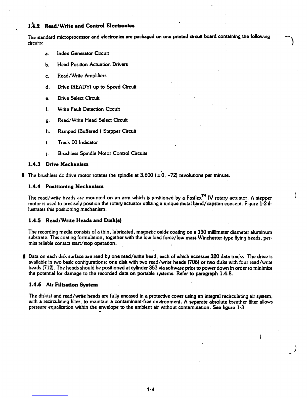
1.4.4
Poaltlonlng
Mechanl
••
The
read/write heads are mounted on an arm
whichispositioned
by
I
Fasflex™
IV
rotary actuator. A stepper
motor
is
usedtoprecisely position the rotary actuator utilizing a unique
metal
band/capstan concept. Figure
1-2
u-
lustrates
thiS
positioning
mechanism. .
1.4.5
Read/Write
Head.
and
DI.k(l)
The
recording
media
consistsofa thin, lubricated, magnetic oxide coating on a 130
mdUmeter
diameter aluminum
substrate.
This
coating formulation, together
with
the
low
load
force/low
mass
Winchester-type
flying
heads, per-
mits
reliable
contact stan/stop operation.
I Data
on
each
disk
surface are read
by
one read/write head, eachofwhich
accesses
320
data tracks.
The
drive
is
availableintwo
basic
configurations: one
disk
with
two read/write heads (706)
or
two
disks
with four read/write
heads
(712).
The
heads should be positioned at cybnder 353 via
IOftware
priorto powerdown
in
order to
minimize
the potential
for
damage to the recorded data on portable systems.
Refer
to paragraph 1.4.8.
1.4.6
AIr flltratioD
Syatem
The
disk(s)
and read/write heads are
fuUy
encased In a protective cover using an integral
recirculating
air
system,
with
a recirculating
filter.
to maintain a contaminant-free environment. A separate absolute breather
filter
allows
pressure equalization within the envelopetothe ambient
air
without contamination.
See
figure 1-3.
.
'-4
)
ACTUATOR
SPINDLE
ASSEMBLY
PJW
HEAD
ASSEMBLY
BAND
STEPPER
.MOTOR
CAPSTAN
*FIGURE 1·2.
READ/WRITE
HEAD
POSITIONING
MECHANISM
.
COVER
0.3 MICRON
BAROMETRIC
FILTER
0.3 MICRON
FILTER
*FIGURE 1·3. AIR FILTRATION SYSTEM
1·5
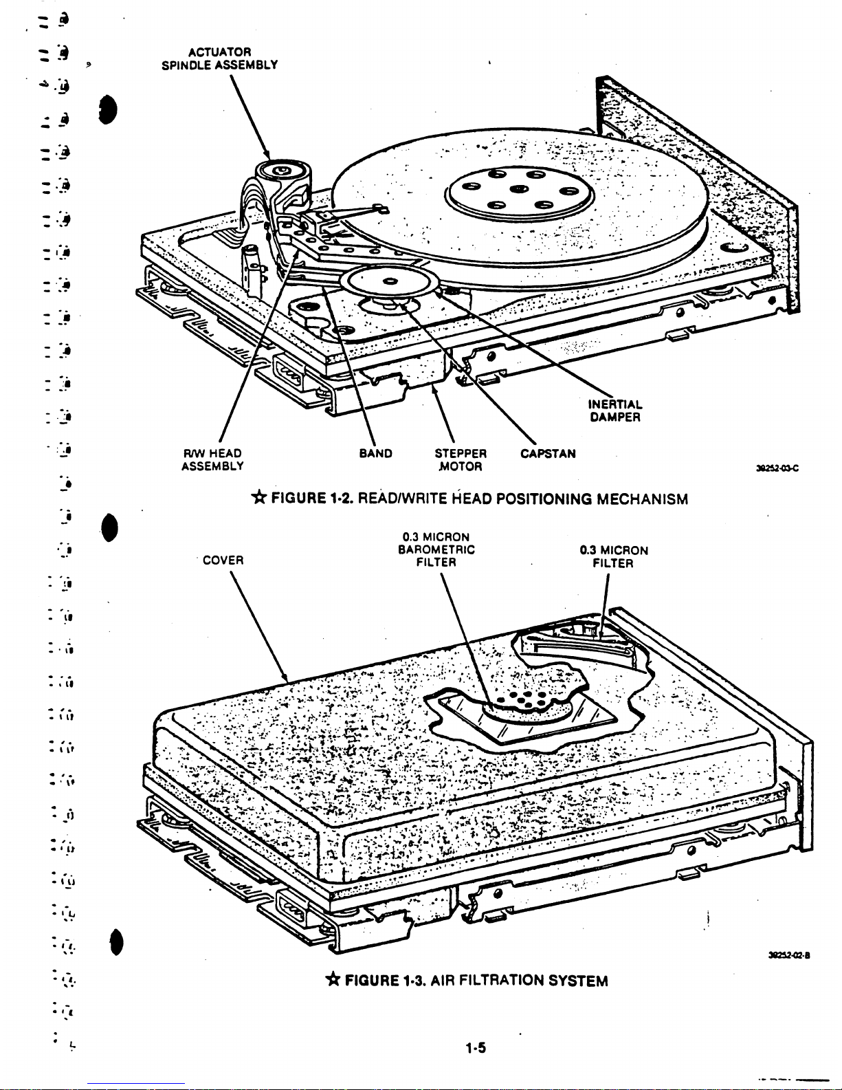
1.4.7 Spindle Lock and Brake
,
These drives
are
provided withanintegral
fall·sal.
spindle
lock
and
brake.
ThIs
lOIenold
operated.
mechanical
brake
is actuated when
de
power
is applied to the drive, allowing the spindle to rotate. When the drive is powered
off,
the
solenoid is deae:ttvated
allowing
the brake to engage
the
spindle.
This
preventsthe
possibilityofdisk
move·
ment
during
shipping or
movement
ofthe drive. During spin down, the
brake
decelerates the spinning
disks
quickly
to
reduce
the
amount
of
time
that
the heads are In unltable flight.
Se.
figure
1-4.
)
STEPPER
MOTOR
BRUSHLESS
DC
SPINDLE
MOTOR
FIGURE 1-4. SPINDLE LOCK
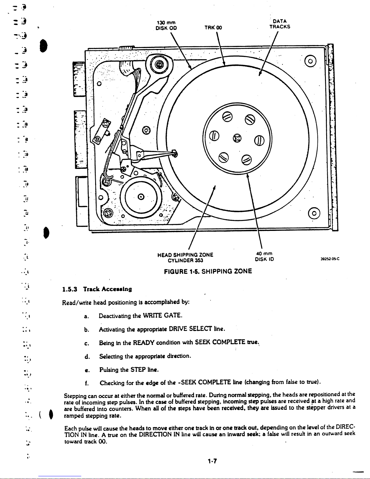
1.4.8
Read/Write
Head
Shipping
Zoae
The
unused
area
ofthe disk surface. Inside
the
data
bands, is designatedasa "shipping
zone."
The
heads
should be
positionedtothis
area
via software before
the
drive15powered off. priortomovingorshipping
the
drive. This en-
sures that if the
drive
is
exposedtosevere handling
(shock).
the
data
storage
area
of
the disk surface
will
not
be
damagedbyheads
movementonthe
disk(s).
See
figure }-5.
1.5
FUNCTIONAL OpERATIONS
1.5.1 Power SequencIDl
The required power-on
sequence
for early production
units
(1.8., 706/712 that are
MLC
4orless)
is that both
the
5
and12volts supplies
be
M
on
" within20secondsofeach
other.
The
orderisnot
important.
No power-on
sequence
is required for
MLC
5 and above.
All
drtves have a
speed
sense ctrcult
to
prevent stepping
until
the
disk
is rotating
at
the
proper
speed
(3,600 rpm). A READY signal
will
be
presentedtothe
controller inter- l
face
once
the
disk is
up
to' Its normal rotational
speed
(:t
2%)
for two seconds.
At
.READV
time, afteraninitial
power-up, the drive will recalibrate Itselftotrack
00.
When the recallbration
procedure
Is complete. SEEK COM-
PLETE
will
go
true. Normal
seek
and
read
functions
can
now
begin. Refertoparagraph
2.6.
! i
·1.5.2 Drive SelectlOD )
Drive selection occurs when
one
of
the
DRIVE SELECT Ilnes
II
activated. Only
the
drive appropriately jumpered
will respond to
the
input signals.
and
the
output
signals of that drive
are
then
gatedtothe
controller.
1·8
.,
.'@
-
DATA
TRACKS
40mm
DISK
10
TRt<
00
130
mm
DISK
00
HEAD SHIPPING ZONE
CYLINDER
353
..
· l
.
"
u
"
I,
• lJ
-
.:1
:
..
~
-
...
-
..
....
:~
.•
l
FIGURE 1·5. SHIPPING ZONE
._'
..
,
t I
..
,
.'
,
..
• t•
.'
..
,
1.5.3
Track Acceaalng
Read/write head positioningisaccomplished
by:
a. Deactivating the
WRITE
GATE.
b.
Activating
the
appropriate
DRIVE
SELECT
line
.
c. Being
in the
READY
condition
with
SEEK
COMPlETE
true.\
d. Selecttng the appropriate direction.
e. Pulsing the STEP
Un
•.
f.
Checking
for
the edge of the -SEEK
COMPLETE
line
(changing
from
false
to true).
.
·
..
...
...
( t
Stepping
can
occurateither the
normalorbuffered rate. DUring normal stepping,-the heads
are
repositioned at the
rate of incoming step pulses. In the
case
of
buffered stepping,
Incoming
step pulses
are
received at a high rate and
are
buffered
Into
counters.
When
all
of
the
steps
have
been received, they
are
Issuedtothe
stepper drivers at a
ramped stepping rate.
Each
pulse
will
cause
the headstomove either one track In or one track out,
depending
on the
levelofthe
DIREC-
TION
IN
line. A trueonthe
DIRECTIONINline
wUI
cause an
Inward
seek: a
false
will
result
in
an outward seek
toward track00.
.
t'
'·7
1.~4
Reacl
OperaUoUl
Reading
data
&om
the
d1sk
Is
accompUshecl
by:
a. Deactivating"the
WRITE
GATE
line.
r
b.
Activating the appropriate
D~
SELECT
line.
c. Assuring that
the
drive
ts
READY.
d. Selecting the appropriate head.
1.5.5 Write Operation
Writing data onto the
disk
is accomplished by:
a. Activating the appropriate
DRIVE
SELECT
Une.
b. Assuring that
the
drive is
READY.
c.
Clearing
any
write
fault
conditions (if that exist).byreselceting the drive.
d.
Selecting the
proper
head.
e.
Activating
the
WRITE
GATE
and plactng dataonthe
WRITE
DATA
Un
••
1.5.6
Head
Selection
Any
of
the
twotofour
possible
heads can
be
selededbyplacing
the
binary
address of that head on the
two
HEAD
SELECT
Unes.
1·8
)
\
~
t
- J
• .J
·
• .J
•
.1
: -'
:
:~
,
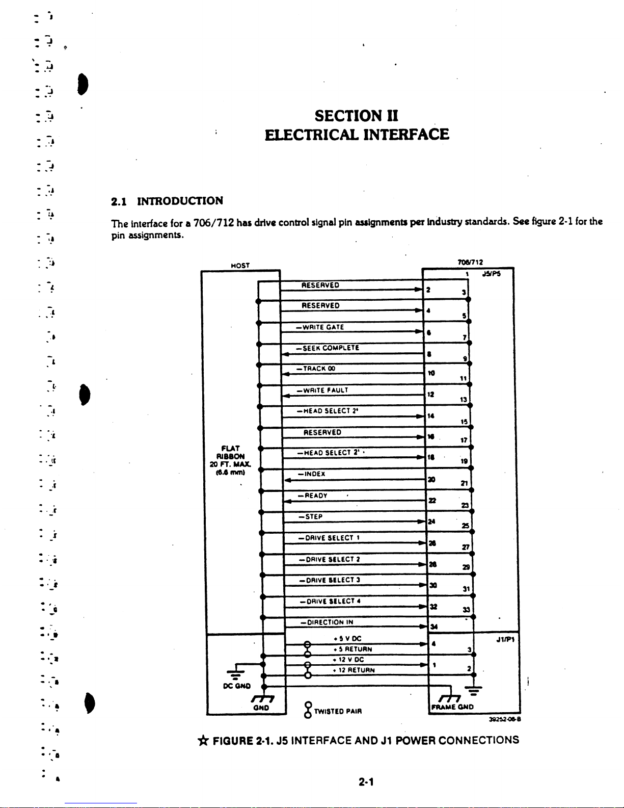
SECTION
II
ELECTRICAL
INTERFACE
2.1
INTRODUCTION
The interface for a
706/712
has
drive
control signal pin ualgnmentl
per
Industry standards. See figure 2·1
for
the
pin assignments.
HOST
7OeI712
• l.
.1
..
1
(.
.1
'.
-
tC
-
•
,r
-
.r
• I
· .
·
."
· .
·
'-'
·
,.
.
-'
.,.
·.
•
',a
· "
• •
-
..
-
• •
• •
,
~~
RESERVED
-
2
-
3
RESERVED
-
•
5
-WRITE
GATE
-
•
7
-SEEK
COMPLETl
~
•
t
-TRACK
00
10
"
-WR'TE
FAULT
I'
13
-HEAD
SELECT
2'
-
t.
-
15
RESERVED
11.
-
17
FLAT
-HEAD
SELECT
2' •
AlIBON
-
'1
20 FT. MAX.
11
ce"mm)
-INDEx
-
a
~
~
-~EADY
22
23
-STEP
-
N
25
-DAIVE
SELECT
t
-
a
zr
-DRIVE
SILECT 2
•
-
21
-DAIVE
IllECT
3
-
-
3D
31
- DRIVI SILECT •
-
-
3Z
33
-DIRECTION IN
.
-
,.
--..
•~v
DC
..,,1P1
A
•~RETURN
-
•
3
-
•
'2YDC
-
-
..£:
X
•12RETURN
-
1
2
-
~
DCGNO
rh--=-
rJ
GND
TWISTED
PAIR
IfRAUEGND
*FIGURE 2·1. J5 INTERFACE
AND
J1
POWER
CONNECTIONS
2·1
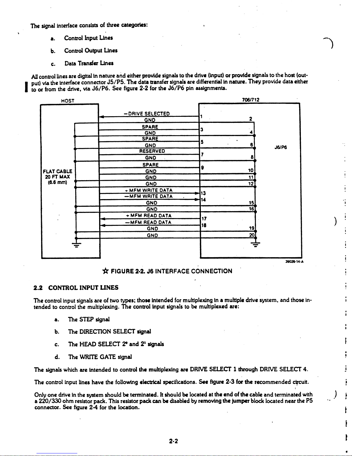
The
sJgna11nterface
consists of three categories:
a. Control Input
Una
b.
Control Output
Una
c.
Data
Transfer
Una
AD
control
lines
are digitalin nature
and
either provide
signalstothe drive (input) or provide signals to the host (out-
I
put) viathe interface connector
JS/P5.
The data transfer slgnall
are
differentialln nature. They provide data either
toorfrom
the drive.
via
J6/P6. See
figure
2-2
for
the
J6/P6
pin
assignments.
HOST
706n12
-
DRIVE
SELECTED
1
-
GND
2
SPARE
3
GND
~
SPARE
5
GNO
8
J6/Pe
RESERVED
7
GND
8
SPARE
,
FLAT
CABLE
GND
10
20FTMAX
GND
'1
(8.6
mm)
GND 12
+ MFM WRITE DATA
13
-MFM
WRITE DATA
-
GND
-
,
..
15
GND
16
-
+ MFM
READ
DATA
17
-
-MFM
READ
DATA
-
18
-
GNO
19
GND
20
--:
-
..
~
)
*FIGURE 2·2.
J6
INTERFACE CONNECTION
2.2
CONTROL INPUT UNES
The control1nput
signals
are
of
two
types; those Intended for multiplexing In a multiple drive system,
and
those in-
tended to control the multiplexing. The controllnput Ilgnals tobemultiplexed are:
a. The STEP signal
b.
The
DIRECTION
SELECT
signal
c.
The
HEAD
SELECT
20
and 2
1
signals
d. The
WRITE
GATE
signal
The
signals
which
are intended
to
control
the
multiplexing
are
DRIVE
SELECT
1through
DRIVE
SELECT
4.
The controllnput lines have the following .lectrical specifications.
541.
figure
2-3 for the recommended
cIrCuit.
Only
one
drive
In the system should
be
terminated. h shouldbelocated at the end ofthe cable and terminated
with
a 220/330 ohm resistor pack. This resistor pack can
be
disabledbyremoving the jumperblock located near the P5
connector. See
figure
2-4 for the location.
)
t
l
t
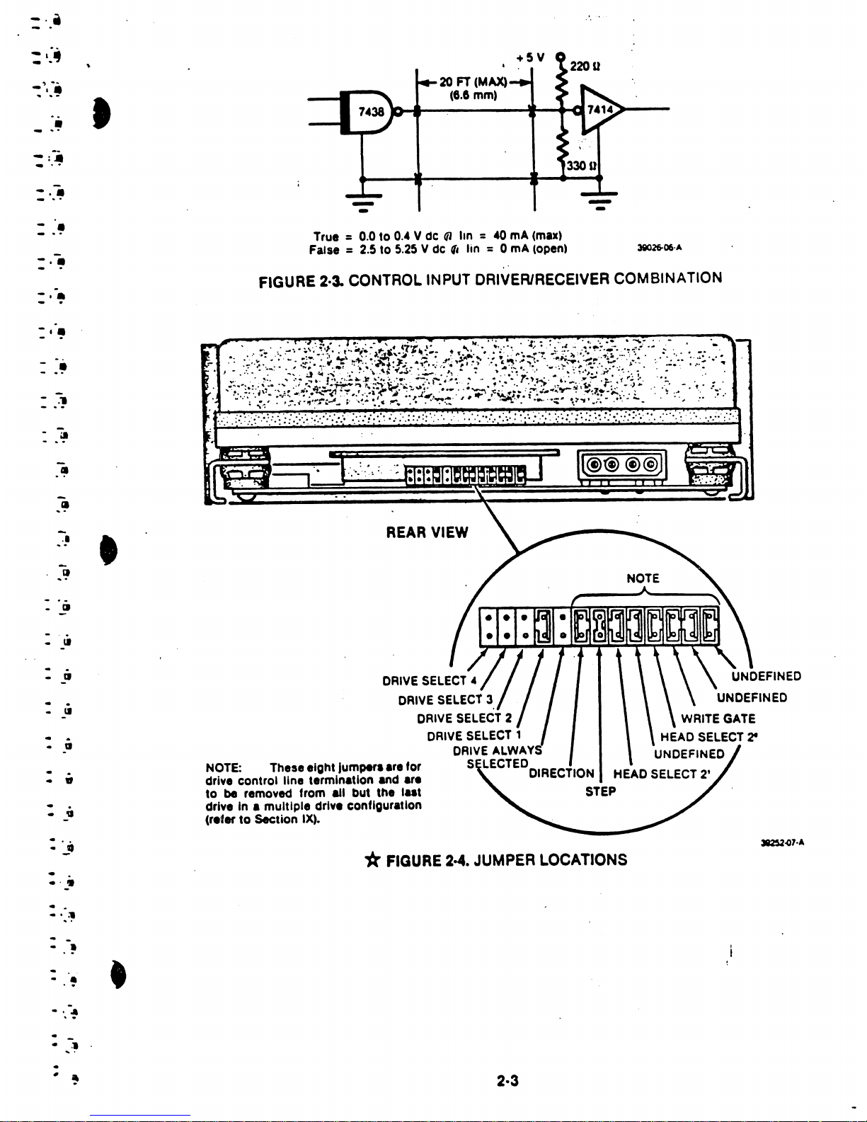
UNDEFINED
UNDEFINED
WRITE
GATE
HEAD
SELECT
21
UNDEFINED
20
FT
(MAX)
(6.0
mm)
DRIVE
SELECT. I /
DRIVE
SELECT
3./
.j
DRIVE
SELECT
2
DRIVE
SELECT
1
DRIVE
ALWAYS
5
LECTED
DIRECTION HEAD SELECT
2'
STEP
REAR
VIEW
*
FIGURE
2·4.
JUMPER LOCATIONS
- -
- -
True =0.0 to 0
.•Vdefllin=.0mA(max)
False
=2.5
to
5.25 V
de
" lin =0
mA
(open) 3i026-06·A
FIGURE 2·3. CONTROL
INPUT
DRIVER/RECEIVER COMBINATION
NOTE: These
eight
Jumper.are
for
drive control line termination and
.r.
to
be removed from ai, but the
Int
drive in a multiple drive configuraUon
(r.fertoSection IX).
.1
•
C!I
• 'II
-
II
• •
•
II
-
..
-
tI
....
· .
-
II
· .
• a
-
i
-
~
l·~
....
")
-
...
~l
..
!
-
..
~
t
..
:
..
~
..
-
..
ill
-
-
.~
-
-
•
-
-
.
•
-
-
.
•
~
-
-
.~
-
...
-
-
..
·.
• '..=!I
· -
·.
~
-
.,
.
.,
2·3
 Loading...