

Page 1

Instruction
Z-Wave PC based Controller v5 User Guide
Document No.:
INS13114
Version:
20
Description:
-
Written By:
JFR;SEROMAN1;SCBROWNI;VOSAVOST;OBOIKO
Date:
2020-12-01
Reviewed By:
JKA;COLSEN;CRASMUSSEN;LTHOMSEN;JBU;JSI;ABUENDIA;RREYES;SEROMAN1;SCB
ROWNI;JFR
Restrictions:
Public
Approved by:
Date CET Initials Name Justification
2020-12-01 09:21:45 NTJ Niels Johansen
This document is the property of Silicon Labs. The data contained herein, in whole or in
part, may not be duplicated, used or disclosed outside the recipient for any purpose. This
restriction does not limit the recipient's right to use information contained in the data if it
is obtained from another source without restriction.
Page 2

INS13114-20 Z-Wave PC based Controller v5 User Guide 2020-12-01
silabs.com | Building a more connected world.
Page ii of ix
REVISION RECORD
Doc.
Rev
DateByPages affected
Brief description of changes
1
20141217
SRO;AVA;VSA
All
Initial version based on INS10240-13
20150226
SRO;AVA;VSA
All
Updated all screenshots,
Updated Association, Command Class, Encrypt/Decrypt, Firmware
Update, Backup/Restore NVM topics
Added IMA, Settings Trace Capturing, Polling functionality, Setup
Route functionality topic
20150226
SRO
4.20.1
Added Power shell script example
2
20160128
SRO;VSA
All
3.1.1
0
3.2
3.2.3
3.2.4
3.4
3.10
3.14, 4.15
3.15,
4.1
4.2.2
4.2.5
4.2.10
4.2.22
4.2.20
Update all screenshots
Added new settings view
Updated description for Security S0 test settings and added
description for Security S2 keys and test settings
Update list of views available from start screen
Described ‘Floating View’ option
Added screenshot for additional Bridge Controller actions (Add,
Remove virtual)
Updated description of the available nodes’ actions including
Security S2-related actions
Added screenshot for additional Bridge Controller action (Slave
Learn Mode)
Updated description of the available controller actions
Added description of the Set Node Information action.
Updated description of the available options on the Command
Classes view
Added Security S2 Encrypt/Decrypt description
Added: Configuration Command Class support
Added: UL Monitor Tool
Update Table1
Added: Nodes with Endpoints
Added: NWE
Added warning screenshot if SIS already present in network
Added: Select Security scheme
Added: Reset SPAN
3
20160224
SRO
All
3.1.1
4.2.1
Update all screenshots
Updated: Settings also contains connection args input field
Changed: added secure S2 node inclusion dialogs description
4
20160708
SRO
3.1.1
3.2
3.2.4
3.3
3.1, 3.2, 3.2.3
3.2.4
Updated Tab S2 Security Test Scheme topic (new test settings and
CSA option)
Updated screenshot
Updated screenshot and added MPAN table description
Updated Association view screenshot and description
Added screenshots for Z/IP controller
Added screenshots for Z/IP controller, Unsolicited destination
description
20160708
SRO
4.5
Updated topic
5
20160726
AVASILEVSKY
4, 4.2.1
Added reminders to set up unsolicited destination for Z/IP Gateway
20160726
AVASILEVSKY
3.4
Update command classes view screenshot
Added description of ‘Auto increment’ session id functionality for
supervision encapsulation
20160805
AVASILEVSKY
4.14
Added clarifications on how NVM restores from zip and hex files
6
20160912
AVASILEVSKY
3.1, 3.2, 3.11, 4.2
Updated screenshots
Added description for new buttons and views
20160913
AVASILEVSKY
4.7
Added explanations how to configure security test schema
20160927
JFR
1.3
Updated necessary tools for PC-based Controller build environment.
7
20161206
SRO
2.3
Updated installation steps
Page 3

INS13114-20 Z-Wave PC based Controller v5 User Guide 2020-12-01
silabs.com | Building a more connected world.
Page iii of ix
REVISION RECORD
Doc.
Rev
DateByPages affected
Brief description of changes
All
Updated screenshots
Removed “Start the Z-Wave PC Controller” section
3.1.1.4
Updated section: Security Test Schema Button
4.7
Updated section: Security Test Schema view
4.12
Added S2 message encapsulation frame decrypt description
20161212
SRO
4.14
Include mention of the wake-up settings of the Sensor PIR nodes
Removed image “Node settings pop-up window”
3.1.1.4
Added property “Is Broadcast”
4.7.2
Added property “Is Broadcast” explanation
Removed “UL Tool Monitor View” section
Removed “UL Tool Monitor” Section
3.15
Added “Smart Start View” section
4.16
Added “Smart Start” section
All
Updated screenshots
8
20170922
VSAVOSTIANENKO
4.7.3
Added description of “Applied Action” and updated examples
9
20180305
BBR
All
Added Silicon Labs template
10
20180531
SRO
1.3
Updated to .Net Framework 4.5
11
20180601
VSAVOSTIANENKO
All
Updated all screenshots
20180601
VSAVOSTIANENKO
3.2.4
Updated selection learn mode
20180601
VSAVOSTIANENKO
3.4
Added additional buttons
20180601
VSAVOSTIANENKO
4.16
Updated view description
20190315
JFR
All
Fixed page numbers
12
20190320
AYurttas
All
TechPub reviewed revision
13
20190520
VOSAVOST
All
Updated all screenshots
3.2.3
Added Identify button
4.2.18
Added Identify button description
3.16
Added Transmit Settings UI
4.17
Added Transmit Settings UI description
20190520
SEROMAN1
1.3 & 2.1
Updated sections
14
20190523
SCBROWNI
2.1 & 4.17
Typos1520190613
VOSAVOST
2.2
Updated section “Required Z-Wave Hardware”
3.16
Updated screenshot and description table
4.17
Updated section “Transmit Settings” and screenshot
20190621
VOSAVOST
4.3
Remove Set Node Info from Controller View functionality section
3.16
Added section “Set Node Information View” section
4.17
Added section “Set Node Information” section
4.1
Updated table
16
20190923
SEROMAN1
3.1.1.1
Updated table and figure
3.1.1.3
Added Section
All
Updated Sections and screenshots
20191203
VOSAVOST
3.1.1.1
Updated Table
3.2.4
Updated “unsolicited destination view” description
All
Updated screenshots
20200326
VOSAVOST
All
Added and updated List of tables and Indexes
20200327
VOSAVOST
All
Review changes, updated references and punctuation
17
20200528
SCBROWNI
All
Technical Publications Review
20200603
VOSAVOST
4.5.1
Fixed typo
18
20200618
SEROMAN1
All
Updated screenshots related to Long Range feature
3.2.1, 3.15, 4.16
Added 'LR flag', added 'Node Options'
19
20201124
VOSAVOST
All
Updated sections and screenshots
3.1.1.4
Added Long Range Network Keys
Page 4

INS13114-20 Z-Wave PC based Controller v5 User Guide 2020-12-01
silabs.com | Building a more connected world.
Page iv of ix
REVISION RECORD
Doc.
Rev
DateByPages affected
Brief description of changes
3.1.2
Updated list of content Main View
3.4
Added Send Data History and removed Last Used and Repeat List
from Command Class View
3.17
Added ‘Set LR Channel’
4.2.1
Added SmartStart Long Range inclusion description
3.15
Added ‘Updated’ button
19
20201124
SCBROWNI
All new sections
Review all new or revised sections since last Tech Pub’s review
20
20201201
OBOIKO
3.15
Added 'LR flag' for Z/IP connected Controller
Page 5

INS13114-20 Z-Wave PC based Controller v5 User Guide 2020-12-01
silabs.com | Building a more connected world.
Page v of ix
Table of Contents
1. ABBREVIATIONS............................................................................................................................1
1 INTRODUCTION ............................................................................................................................1
1.1 Purpose..............................................................................................................................................1
1.2 Audience and Prerequisites...............................................................................................................1
1.3 Implementation.................................................................................................................................1
2 THE Z-WAVE PC-BASED CONTROLLER............................................................................................2
2.1 Check the Prerequisites.....................................................................................................................2
2.2 Required Z-Wave Hardware ..............................................................................................................2
2.3 Install the Z-Wave PC Controller .......................................................................................................3
2.4 Remove Z-Wave PC Controller ..........................................................................................................3
3 USER INTERFACE ...........................................................................................................................4
3.1 Main Menu View ...............................................................................................................................4
3.1.1 Title Bar ...................................................................................................................................4
3.1.1.1 Settings...............................................................................................................................4
3.1.1.2 Commands Queue Button..................................................................................................6
3.1.1.3 Send Data Settings..............................................................................................................6
3.1.1.4 Security Test Schema Button..............................................................................................7
3.1.2 Content View.........................................................................................................................11
3.1.3 Log Bar...................................................................................................................................13
3.2 Network Management View ...........................................................................................................14
3.2.1 Node List View.......................................................................................................................16
3.2.2 Node Information View.........................................................................................................17
3.2.3 Nodes Actions View...............................................................................................................17
3.2.4 Controller View .....................................................................................................................21
3.3 Associations View ............................................................................................................................25
3.4 Command Class View ......................................................................................................................26
3.5 Setup Route View ............................................................................................................................30
3.6 ERTT View........................................................................................................................................32
3.7 Polling View .....................................................................................................................................33
3.8 Topology Map View.........................................................................................................................34
3.9 IMA Network View ..........................................................................................................................36
3.10 Encrypt/Decrypt View .....................................................................................................................40
3.11 Firmware Update (OTA) View..........................................................................................................42
3.12 Firmware Update (OTW) View ........................................................................................................44
3.13 Backup/Restore NVM ......................................................................................................................44
3.14 Configuration Parameters ...............................................................................................................45
3.15 Smart Start View..............................................................................................................................45
3.16 Set Node Information View .............................................................................................................47
3.17 Transmit Settings View....................................................................................................................49
Page 6

INS13114-20 Z-Wave PC based Controller v5 User Guide 2020-12-01
silabs.com | Building a more connected world.
Page vi of ix
4 FUNCTIONALITY ..........................................................................................................................51
4.1 The SC Properties ............................................................................................................................52
4.2 Node View .......................................................................................................................................54
4.2.1 How to Add a Node ...............................................................................................................54
4.2.2 How to Add Multichannel Node with EndPoints...................................................................56
4.2.3 How to Remove a Node ........................................................................................................56
4.2.4 Network Wide Inclusion........................................................................................................56
4.2.5 Network Wide Exclusion .......................................................................................................57
4.2.6 Send NOP ..............................................................................................................................57
4.2.7 How to Send a Failure Signal to a Node ................................................................................57
4.2.8 How to Replace a Failed Node ..............................................................................................57
4.2.9 How to Remove a Failing Node .............................................................................................57
4.2.10 Set SIS....................................................................................................................................58
4.2.11 Request Node Neighbors Update..........................................................................................58
4.2.12 Node Info...............................................................................................................................58
4.2.13 Version Get............................................................................................................................58
4.2.14 Switching a Node or a Subset of Nodes on and off...............................................................58
4.2.15 Set Wake-Up Interval ............................................................................................................59
4.2.16 ‘Switch All On’ Command......................................................................................................59
4.2.17 ‘Switch All Off’ Command .....................................................................................................59
4.2.18 ‘Identify’ Command...............................................................................................................59
4.2.19 Start/Stop Basic Test.............................................................................................................59
4.2.20 Reset SPAN............................................................................................................................59
4.2.21 Next SPAN .............................................................................................................................59
4.2.22 Security Scheme....................................................................................................................59
4.3 Controller View................................................................................................................................60
4.3.1 Reset Controller ....................................................................................................................60
4.3.2 Send Node Info......................................................................................................................60
4.3.3 Controller Shift ......................................................................................................................60
4.3.4 Request Update of PC-based SC............................................................................................60
4.4 Command Class View ......................................................................................................................61
4.5 Association View..............................................................................................................................61
4.5.1 Create Association.................................................................................................................61
4.5.2 Remove Association ..............................................................................................................61
4.6 Setup Route View ............................................................................................................................61
4.6.1 Assign a Route .......................................................................................................................61
4.6.2 Delete a Route.......................................................................................................................62
4.7 Security Test Schema View..............................................................................................................62
4.7.1 Test S2 Parameters Overrides ...............................................................................................62
4.7.2 Test S2 Messages Overrides..................................................................................................63
4.7.3 Test S2 Message Encapsulation Extensions Overrides..........................................................64
4.8 ERTT View........................................................................................................................................65
4.9 Polling View .....................................................................................................................................67
4.10 Topology Map View.........................................................................................................................67
4.11 IMA Network View ..........................................................................................................................67
Page 7

INS13114-20 Z-Wave PC based Controller v5 User Guide 2020-12-01
silabs.com | Building a more connected world.
Page vii of ix
4.11.1 Network Health .....................................................................................................................68
4.11.2 Power Level Test ...................................................................................................................68
4.12 Security Encrypt/Decrypt ................................................................................................................68
4.13 Firmware Update.............................................................................................................................70
4.14 NVM Backup/Restore ......................................................................................................................70
4.15 Configuration Parameters ...............................................................................................................71
4.16 Smart Start ......................................................................................................................................71
4.17 Set Controller Node Information.....................................................................................................72
4.18 Transmit Settings.............................................................................................................................74
4.19 Z-Wave PC Controller Log................................................................................................................75
4.20 Settings Trace Capturing .................................................................................................................76
4.20.1 Open Saved Capture Trace File .............................................................................................76
5 REFERENCES................................................................................................................................79
INDEX ................................................................................................................................................80
List of Figures
Figure 1. PC with a Z-Wave Module Connected ..........................................................................................2
Figure 2. Main Menu View ..........................................................................................................................4
Figure 3. Settings View ................................................................................................................................5
Figure 4. Commands Queue View ...............................................................................................................6
Figure 5. Send Data Settings........................................................................................................................6
Figure 6. Security Test Settings....................................................................................................................8
Figure 7. Security Parameter Overrides.......................................................................................................9
Figure 8. Security Message Overrides .......................................................................................................10
Figure 9. Security Extension Overrides ......................................................................................................11
Figure 10. Content View ............................................................................................................................12
Figure 11. Content View with Z/IP Controller Connected .........................................................................13
Figure 12. Log Bar View .............................................................................................................................13
Figure 13. Log Window View .....................................................................................................................13
Figure 14. Network Management View.....................................................................................................15
Figure 15. Network Management View with Z/IP Controller Connected..................................................16
Figure 16. Nodes View...............................................................................................................................16
Figure 17. Node Information View ............................................................................................................17
Figure 18. Nodes Actions View ..................................................................................................................17
Figure 19. Nodes Actions View when Z/IP Controller Connected .............................................................18
Figure 20. Bridge Controller Additional Actions ........................................................................................18
Figure 21. Add Custom ..............................................................................................................................20
Figure 22. Controller View.........................................................................................................................21
Figure 23. Z/IP Controller View..................................................................................................................21
Figure 24. Select Learn Mode ....................................................................................................................21
Figure 25. Bridge Controller Additional Action..........................................................................................22
Figure 26. Mpan Table View ......................................................................................................................23
Page 8

INS13114-20 Z-Wave PC based Controller v5 User Guide 2020-12-01
silabs.com | Building a more connected world.
Page viii of ix
Figure 27. Unsolicited Destination View....................................................................................................24
Figure 28. Associations View .....................................................................................................................25
Figure 29. Command Classes View ............................................................................................................27
Figure 30. Select Command View ..............................................................................................................30
Figure 31. Setup Route View .....................................................................................................................30
Figure 32. ERTT View .................................................................................................................................32
Figure 33. Polling View ..............................................................................................................................33
Figure 34. Topology Map...........................................................................................................................34
Figure 35. IMA Network View....................................................................................................................36
Figure 36. IMA Network Health Status Description (Details) ....................................................................38
Figure 37. IMA Network Health Value Description (Legend).....................................................................39
Figure 38. IMA Nodes View Description (Legend) .....................................................................................40
Figure 39. Encrypt/Decrypt View S0 Tab ...................................................................................................41
Figure 40. Encrypt/Decrypt View S2 Tab ...................................................................................................41
Figure 41. Firmware Update (OTA) View...................................................................................................42
Figure 42. File Dialog View.........................................................................................................................44
Figure 43. NVM Backup/Restore View ......................................................................................................44
Figure 44. Configuration Parameters View................................................................................................45
Figure 45. Smart Start View.......................................................................................................................46
Figure 46. Z/IP Controller Connected Smart Start View ............................................................................46
Figure 47. Set Node Info View ...................................................................................................................48
Figure 48. Transmit Settings View .............................................................................................................49
Figure 49. Popup Message After Pressing 'Add' Button ............................................................................55
Figure 50. Network Keys Request..............................................................................................................55
Figure 51. Enter DSK Dialog .......................................................................................................................55
Figure 52. Multi Channel Node with End Points View ...............................................................................56
Figure 53. Popup Message After Pressing 'Remove' Button .....................................................................56
Figure 54. Set SIS Warning Message..........................................................................................................58
Figure 55. Select Security Scheme Dialog..................................................................................................59
Figure 56. Test Frame Configuration for Example 1 ..................................................................................63
Figure 57. Test Frame Configuration for Example 2 ..................................................................................64
Figure 58. Last Used Temp Key..................................................................................................................68
Figure 59. S2 Message Encapsulation Frame.............................................................................................69
Figure 60. S2 Message Encapsulation Frame Hex Data .............................................................................69
Figure 61. S2 Message Encapsulation Frame Decrypt ...............................................................................70
Figure 62. Provisioning List Item Delete Popup.........................................................................................71
Figure 63. Smart Start Added Device Locally Reset Popup........................................................................71
Figure 64. Set Node Information view.......................................................................................................72
Figure 65. Device options ..........................................................................................................................73
Figure 66. Generic options ........................................................................................................................73
Figure 67. Specific options.........................................................................................................................74
Figure 68. Role Types.................................................................................................................................74
Figure 69. Node Types ...............................................................................................................................74
Figure 70. Transmit Settings Tx Power Level .............................................................................................75
Figure 71. Select RF Region setting............................................................................................................75
Page 9

INS13114-20 Z-Wave PC based Controller v5 User Guide 2020-12-01
silabs.com | Building a more connected world.
Page ix of ix
Figure 72. Select LR Channel......................................................................................................................75
List of Tables
Table 1. Settings View Items........................................................................................................................5
Table 2. Commands Queue View Items.......................................................................................................6
Table 3. Send Data Settings Items ...............................................................................................................7
Table 4. Security Test Settings View Items ..................................................................................................8
Table 5. Log View Items.............................................................................................................................14
Table 6. Node Actions View Items .............................................................................................................19
Table 7. Controller Actions View Items .....................................................................................................22
Table 8. General Information View Items..................................................................................................23
Table 9. MPAN View Items ........................................................................................................................24
Table 10. Unsolicited View Items ..............................................................................................................24
Table 11. Association View Items ..............................................................................................................26
Table 12. Send Data View Items ................................................................................................................28
Table 13. Select Command View Items .....................................................................................................30
Table 14. Setup Route View Items.............................................................................................................31
Table 15. ERTT View Items.........................................................................................................................32
Table 16. Polling View Items......................................................................................................................33
Table 17. Topology Map View Items .........................................................................................................35
Table 18. IMA Network View Items...........................................................................................................37
Table 19. IMA Details View Items..............................................................................................................38
Table 20. IMA Nodes View Items...............................................................................................................40
Table 21. Encrypt/Decrypt S0 View Items .................................................................................................41
Table 22. Encrypt/Decrypt S2 View Items .................................................................................................42
Table 23. Firmware Update OTA View Items.............................................................................................43
Table 24. NVM Backup/Restore View Items..............................................................................................45
Table 25. Configuration Parameters View Items .......................................................................................45
Table 26. Smart Start View Items ..............................................................................................................47
Table 27. Set Node Info View Items ..........................................................................................................49
Table 28. Transmit Settings View Items ....................................................................................................50
Table 29. Overview of the Static Controller Properties.............................................................................53
Page 10

INS13114-20 Z-Wave PC based Controller v5 User Guide 2020-12-01
silabs.com | Building a more connected world.
Page 1 of 80
1. ABBREVIATIONS
Abbreviation
Explanation
API
Application Programming Interface
DLL
Dynamic Link Library
IMA
Installation and Maintenance Application
NVM
Non-volatile memory
OTA
Over-the-air
OTW
Over-the-wire
SC
Static Controller
SUC
Static Update Controller
SIS
SUC ID Server
ERTT
Enhanced Reliability Test Tool
DSK
Device-Specific Key
LR
Long Range
1 INTRODUCTION
1.1 Purpose
The Z-Wave PC-based Controller application is an example on how Static/Bridge Controller Serial API
functionality can be used to implement a Z-Wave-enabled PC application.
1.2 Audience and Prerequisites
The audience is Z-Wave partners and Silicon Labs. It is assumed that the Z-Wave partner is already
familiar with the current Z-Wave Developer's Kit.
1.3 Implementation
The Z-Wave PC-based Controller application requires the .NET Framework 4.6.1 or higher. It’s based on
the Z-Wave DLL.
Note: See [3] Regarding a detailed description about the Z-Wave DLL.
Page 11
INS13114-20 Z-Wave PC based Controller v5 User Guide 2020-12-01
silabs.com | Building a more connected world.
Page 2 of 80
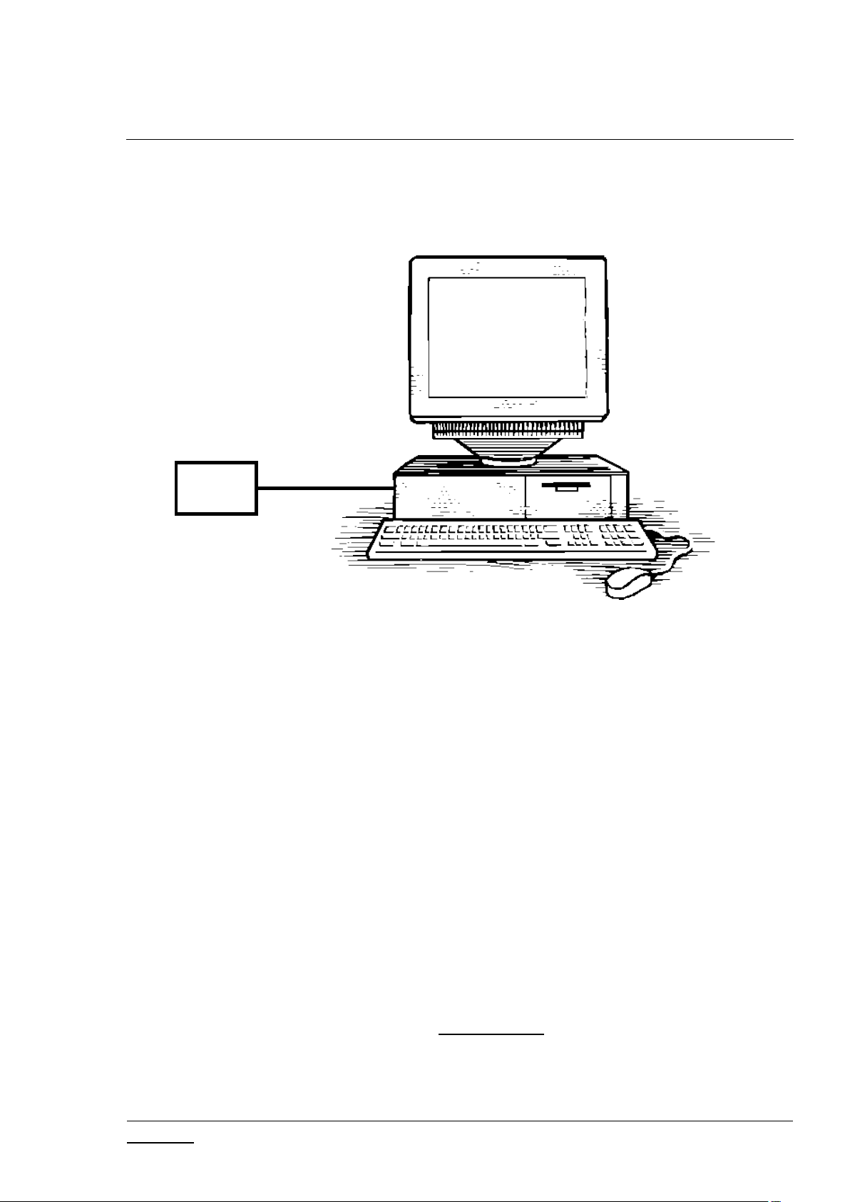
2 THE Z-WAVE PC-BASED CONTROLLER
Z-Wave
module
The Z-Wave PC-based Controller is an application designed for the Windows platform that is capable of
communicating with Z-Wave nodes like switches and sensors through a Static Controller (SC).
Figure 1. PC with a Z-Wave Module Connected
2.1 Check the Prerequisites
The .NET Framework 4.6.1 or later must be installed on the machine to run the Z-Wave PC-based
Controller Windows application.
Limitation: Z-Wave PC Controller has been tested on Windows 10.
Important: Ensure that you have the latest service pack and critical updates for the version of Windows
that you are running.
2.2 Required Z-Wave Hardware
Z-Wave PC Controller application requires a Z-Wave module programmed with a Serial API application,
including next library types: Static Controller, Bridge Controller, Portable Controller, Slave Enhanced
and connected to the appropriate serial or USB port.
To program the Z-Wave module, use the firmware HEX file and additional programming tool:
- For devices with ZW070x chip series use Simplicity Studio and choose needed application from
latest available Z-Wave SDK demos.
Page 12

INS13114-20 Z-Wave PC based Controller v5 User Guide 2020-12-01
silabs.com | Building a more connected world.
Page 3 of 80
- For other devices with chip series older than ZW070x use Z-Wave Programmer tool and file by
next name pattern: serialapi_<Lib_Type>_ZW050x_XX.hex (USB version has
USBVCP in its name) located in the directory
‘C:\DevKit_X_YY\SDK\ProductPlus\Bin\ SerialAPI_Controller_Static\’;
Finally, connect the Z-Wave module to the COM port on the PC.
UZB is the Z-Wave USB Adapter. It is a USB-based Static Controller.
As the device exports a USB CDC/ACM class-compliant interface, it appears as a serial port, reusing
existing standard drivers on the most popular PC operating systems. As such, there is no vendor driver
required. Over the serial port, the Z-Wave Serial API is exported.
UZB.INF is provided that reuses the standard Windows usbser.sys or usbser64.sys driver. The device
appears in the Device Manager under the Ports section, and is accessible through the Windows
CreateFile API by applications as “//.//COMxxx” where xxx is the COM Port number assigned by the OS.
For more information on UZB, see INS11850, Instruction, UZB User Manual.
2.3 Install the Z-Wave PC Controller
Perform the following steps to install the Z-Wave PC Controller:
1. Exit all programs.
2. Run the installation file of the Z-Wave PC Controller application and follow the installation
wizard.
3. The actual installation procedure will pass with progress indicator and final confirmation
appears.
4. Click Finish to complete the installation.
2.4 Remove Z-Wave PC Controller
You can uninstall Z-Wave PC Controller from your computer if you no longer use it.
1. Open “Add or Remove Programs” in Control Panel.
Click “Start”, click “Control Panel” (in Classical View – click “Start”, point to “Settings”, click
“Control Panel”), and then double-click “Add or Remove Programs”.
2. Click the program in the list and then click the “Remove” button. You can sort programs by
selecting different options in “Sort by”.
3. Standard confirmation dialog appears. Click “Yes” to continue the removal of the Z-Wave PC
Controller software.
4. Z-Wave PC Controller and its settings will be removed without further prompting.
Page 13
INS13114-20 Z-Wave PC based Controller v5 User Guide 2020-12-01
silabs.com | Building a more connected world.
Page 4 of 80
3 USER INTERFACE
3.1 Main Menu View
The Z-Wave PC Controller application's Main menu view consists of the following items:
Title bar
Content view (current view depends on selected button on Main menu view)
Log bar
3.1.1 Title Bar
The Title bar is located on top of the Main Menu View. It is accessible from any view. It has the
following items:
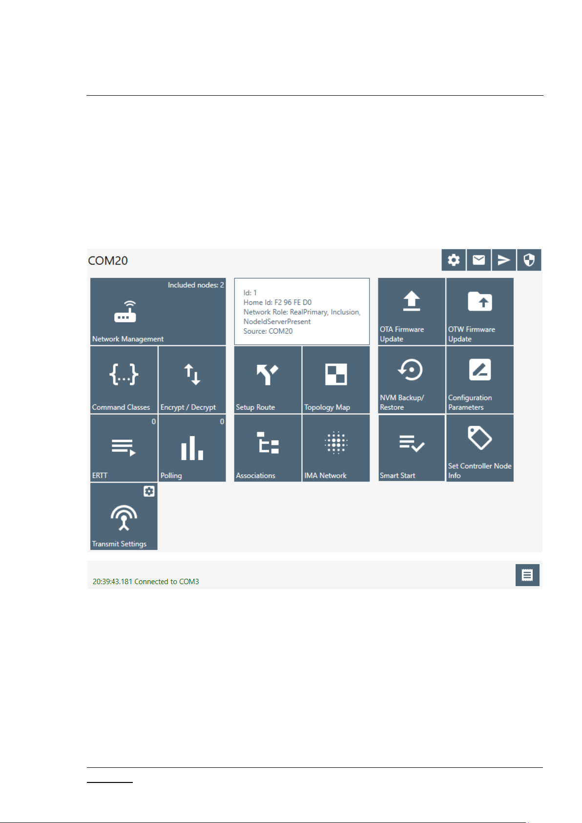
3.1.1.1 Settings
Pressing on the Settings button opens a new window in which a controller device can be selected.
Additionally, users can set up trace capture settings in this window.
Figure 2. Main Menu View
Page 14
INS13114-20 Z-Wave PC based Controller v5 User Guide 2020-12-01
silabs.com | Building a more connected world.
Page 5 of 80
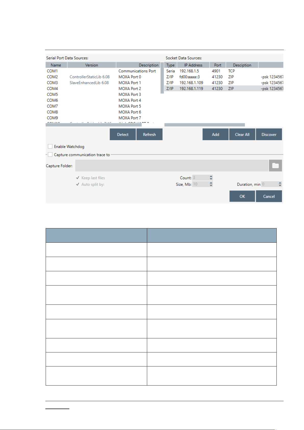
Figure 3. Settings View
Menu item
Description
Detect
Detects library type for available devices.
Refresh
Refreshes list of connected devices.
Clear All
Clears list of Socket Data Sources.
Discover
Detects available Socket Data Sources. ZIP Gateway
and WSTK boards connected via IP.
Add
Adds custom IP Address to list.
Enable Watchdog
Turn On/Off Watchdog command for ZW070x
devices.
Capture communication trace to
Enables trace capturing.
… (Browse for Folder)
Selects folder for saving files of capture.
Auto split
Enables splitting files by size and/or duration and
count of file parts.
Table 1. Settings View Items
Page 15
INS13114-20 Z-Wave PC based Controller v5 User Guide 2020-12-01
silabs.com | Building a more connected world.
Page 6 of 80
Ok
Selects chosen COM port as controller and closes the
window and applies changes of trace capturing.
Cancel
Closes the window without changes.
3.1.1.2 Commands Queue Button
Menu item
Description
Delete
Deletes selected command from queue.
Clear
Clears queue.
Pressing the “Commands Queue” button shows the queue commands for nodes in the new window.
Each node has its own group.
Figure 4. Commands Queue View
Table 2. Commands Queue View Items
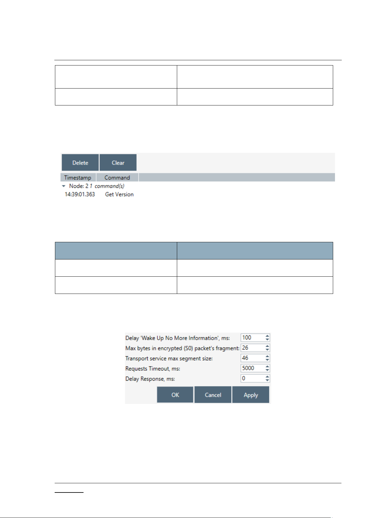
3.1.1.3 Send Data Settings
Opens view with Send Data options for easy navigation and setup data from any other view
Figure 5. Send Data Settings
Page 16

INS13114-20 Z-Wave PC based Controller v5 User Guide 2020-12-01
silabs.com | Building a more connected world.
Page 7 of 80
Table 3. Send Data Settings Items
Menu item
Description
Delay ‘Wake Up No More Information’
Sets additional delay in ms to respond with Wake Up
No More after releasing commands queue for nonlistening receiver.
Max bytes in encrypted (S0) packet’s
fragment
Sets the maximum length in encrypted packet
fragments.
Transport service max segment size
Sets the Transport service maximum segment size.
Reads max payload length from device. Default value
is 46 bytes.
Request Timeout
Changes wait time in ms for request commands
responds.
Delay Response
Sets additional delay in ms to respond on any
received data.
Ok
Apply options and close the dialog.
Cancel
Close the dialog with changes.
Apply
Applies set options without closing.
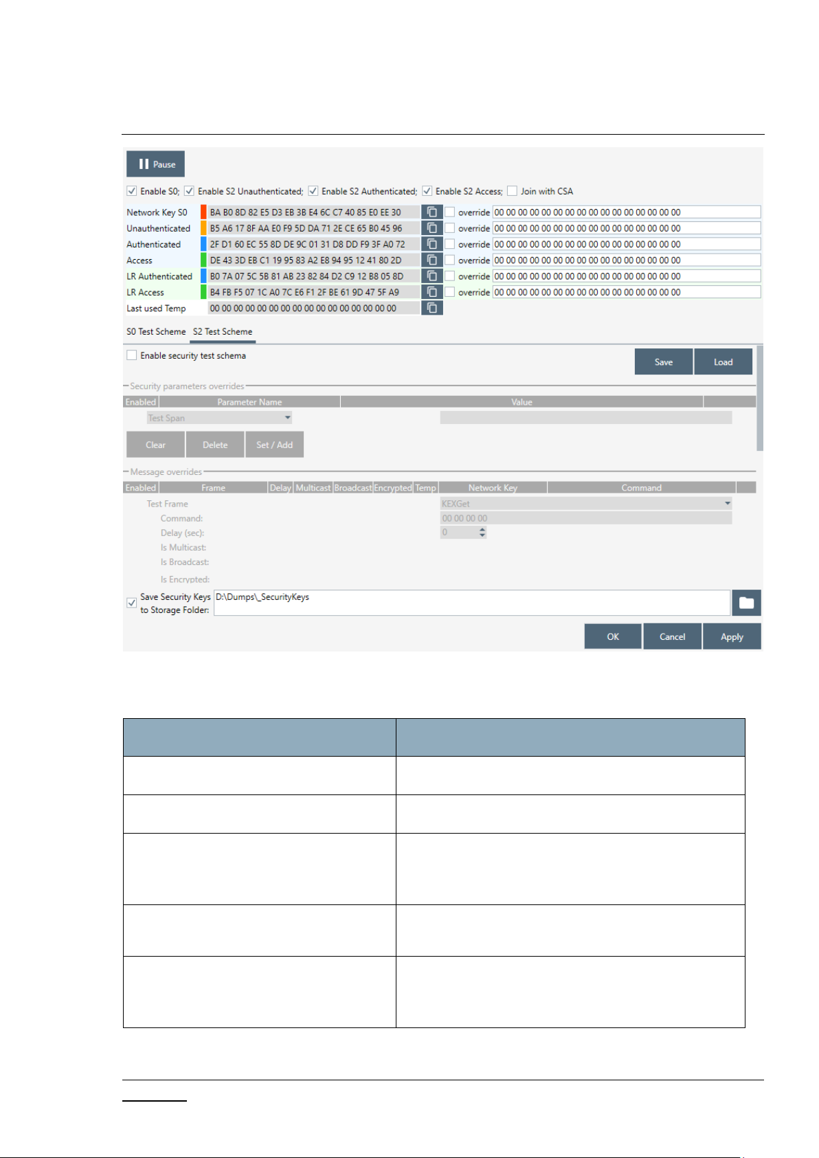
3.1.1.4 Security Test Schema Button
Pressing on the Security Test Schema button opens a new window Security Settings which contains the
list of security network keys and the list of test properties for Security and Security Version 2.
Page 17
INS13114-20 Z-Wave PC based Controller v5 User Guide 2020-12-01
silabs.com | Building a more connected world.
Page 8 of 80
Figure 6. Security Test Settings
Menu item
Description
Save
Saves the current Security S2 test schema to file.
Load
Loads the Security S2 test schema from file.
OK
Applies current Security settings and Security Test
Settings if enabled and closes the Security Settings
dialog.
Cancel
Closes the Security Settings dialog without applying
changes.
Apply
Applies current Security settings and Security Test
Settings if enabled without closing the Security
Settings dialog.
Table 4. Security Test Settings View Items
Page 18
INS13114-20 Z-Wave PC based Controller v5 User Guide 2020-12-01
silabs.com | Building a more connected world.
Page 9 of 80
The Security Test Schema functionality is available to test secure networks for failures if the device
malfunctions.
Checkboxes “Enable S0”, “Enable S2 Unauthenticated”, “Enable S2 Authenticated”, and “Enable S2
Access” turns on/off corresponding security class.
Checkbox “Join with CSA” allows the PC Controller to send KEX Report with CSA flag set to 1. This flag
will only be set when the PC Controller is included in the network as a secondary controller.
Current Network Keys are shown in grey (disabled editing) textboxes according to security level:
Network Key S0, Unauthenticated, Authenticated, Access and LR Authenticated, LR Access for Long
Range, and Last Used Temp. Near each network key are buttons to copy the value to clipboard and
checkboxes to use the Permanent Key from the white (enabled editing) textbox.
Save Security Keys to Storage checkbox enables saving network keys to file when applying settings,
resetting the controller and when adding the controller to another network. The button “…” changes
the storage folder path. Values will be added to file with the current network home ID name.
Tab S0 Security Test Scheme
Security Test Schema S0 can be configured for both Including Controller and Included Node. To enable
Schema, check the “Enable security test schema” checkbox.
All changes made on this view are applied after clicking the “OK” or “Apply” button.
Tab S2 Security Test Scheme
To enable Schema, check the “Enable security test schema” checkbox. See [4] for more details.
All changes made on this view are applied after clicking the “OK” or “Apply” button.
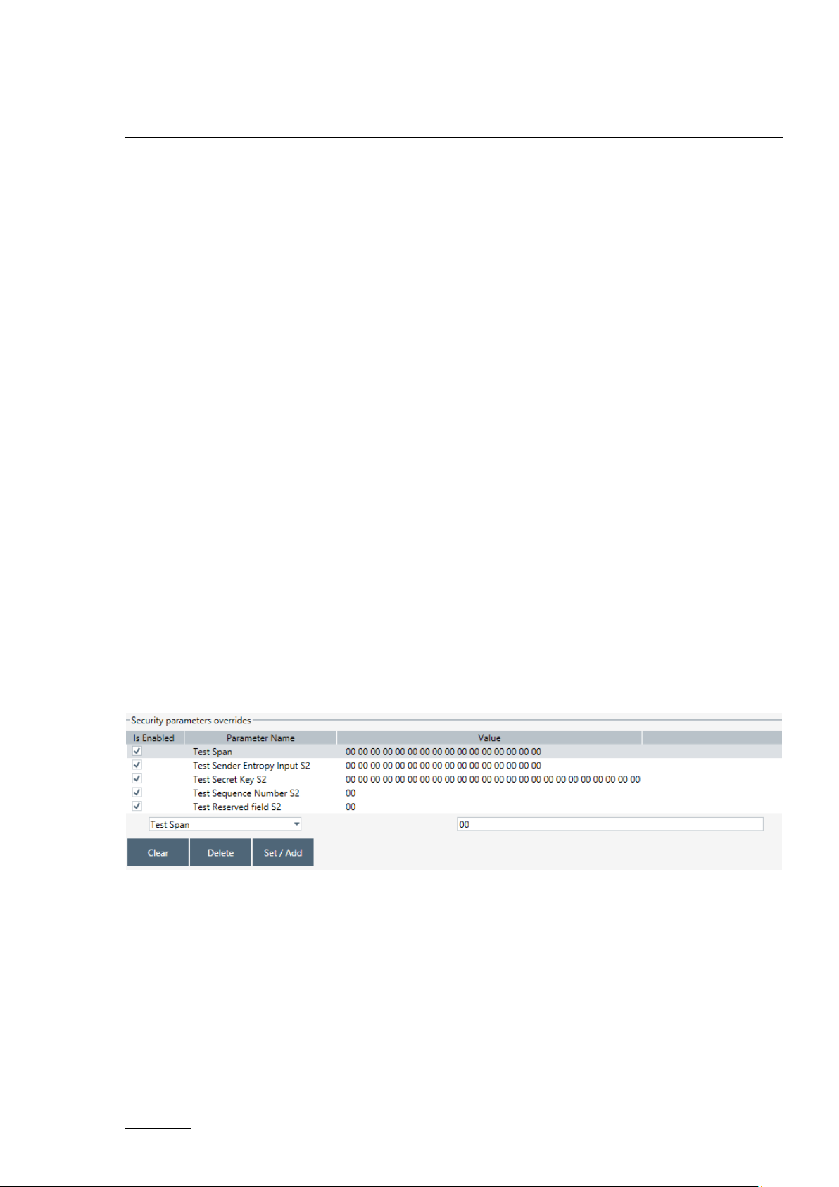
Group “Security parameters overrides” allows changing encryption parameters:
Figure 7. Security Parameter Overrides
Test Span replaces the current SPAN with a specified value during data encryption.
Test Sender Entropy Input S2 replaces the sender Entropy Input with a specified value during
data encryption.
Test Secret Key S2 replaces the current secret key of the S2 keypair. DSK value will be calculated
based on the secret key.
Test Sequence Number S2 replaces the current Sequence Number with a specified value during
data encryption.
Test Reserved field S2 replaces the Reserved field with a specified value during data encryption.
Page 19
INS13114-20 Z-Wave PC based Controller v5 User Guide 2020-12-01
silabs.com | Building a more connected world.
Page 10 of 80
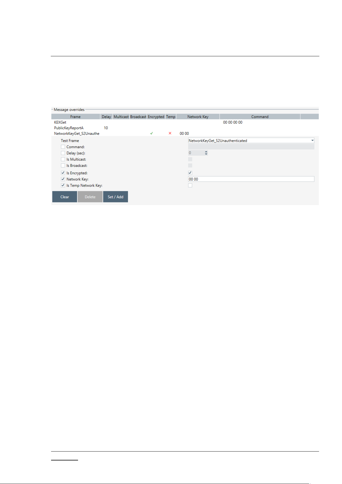
Group “Message overrides” contains a set of test frames with properties: “Command”, “Delay”, “Is
Encrypted”, “Is Multicast”, “Is Broadcast”, “Network Key”, and “Is Temp Network Key”. Click a
corresponding checkbox to activate the parameter override and specify a new value. If the parameter
override is not active, the PC Controller will use a valid specific frame parameter value. For example,
“KEXGet” is not encrypted but KexGetEcho is encrypted if “IsEncrypted” parameter is not active.
Figure 8. Security Message Overrides
Test Frame types:
InjectCommand
KEXGet
KEXReport
KEXSet
PublicKeyReportB – joining node’s Public Key Report frame
PublicKeyReportA – including controller’s Public Key Report frame
KEXSetEcho
KEXReportEcho
NetworkKeyGet_S0
NetworkKeyReport_S0
NetworkKeyVerify_S0
NetworkKeyGet_S2Unauthenticated
NetworkKeyReport_S2 Unauthenticated
NetworkKeyVerify_S2 Unauthenticated
NetworkKeyGet_S2 Authenticated
NetworkKeyReport_S2 Authenticated
NetworkKeyVerify_S2 Authenticated
NetworkKeyGet_S2Access
NetworkKeyReport_S2 Access
NetworkKeyVerify_S2 Access
TransferEndA_S0 – including controller
TransferEndA_S2Unauthenticated– including controller
TransferEndA_S2Authenticated – including controller
TransferEndA_S2 Access – including controller
Page 20

INS13114-20 Z-Wave PC based Controller v5 User Guide 2020-12-01
silabs.com | Building a more connected world.
Page 11 of 80
TransferEndB – joining node
NonceGet
NonceReport
MessageEncapsulation
CommandsSupportedReport
InclusionInitiate1
InclusionInitiate2
InclusionComplete1
InclusionComplete2
The Group “Extension overrides” table allows users to set custom extensions for any S2 Message
encapsulation. Message type filters are as follows: “SinglecastAll”, “SinglecastWithSpan”,
“SinglecastWithMpan”, “SinglecastWithMpanGrp”, “SinglecastWithMos”, and “MulticastAll”. Extension
types are as follows: “Span”, “Mpan”, “MpanGrp”, “Mos”, and “Test”. Other parameters are as follows:
“Is Encrypted”, “Extension Length”, “More To Follow”, “Is Critical”, and “Number of usage”. Click a
corresponding checkbox to activate the parameter override and specify a new value. If the parameter
override is not active, the PC Controller uses a valid specific extension parameter value. For example,
Extension Length will be calculated based on the Extension value unless a specific parameter value is
activated.
The Checkbox “Cleanup existing extensions first” overrides existing extensions in selected message type
when applying test extensions. When this checkbox is not set, test extension will be added to default
extensions.
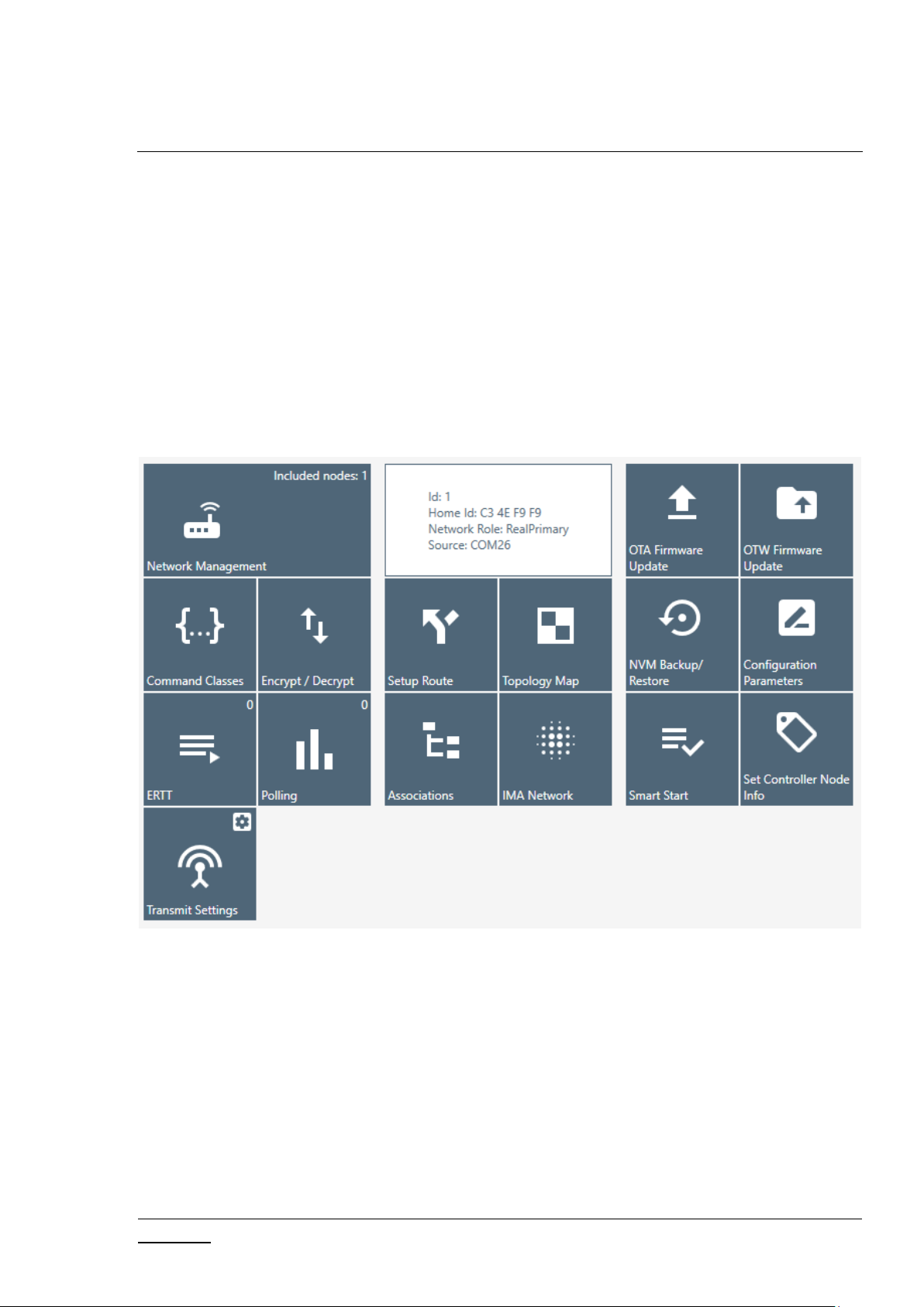
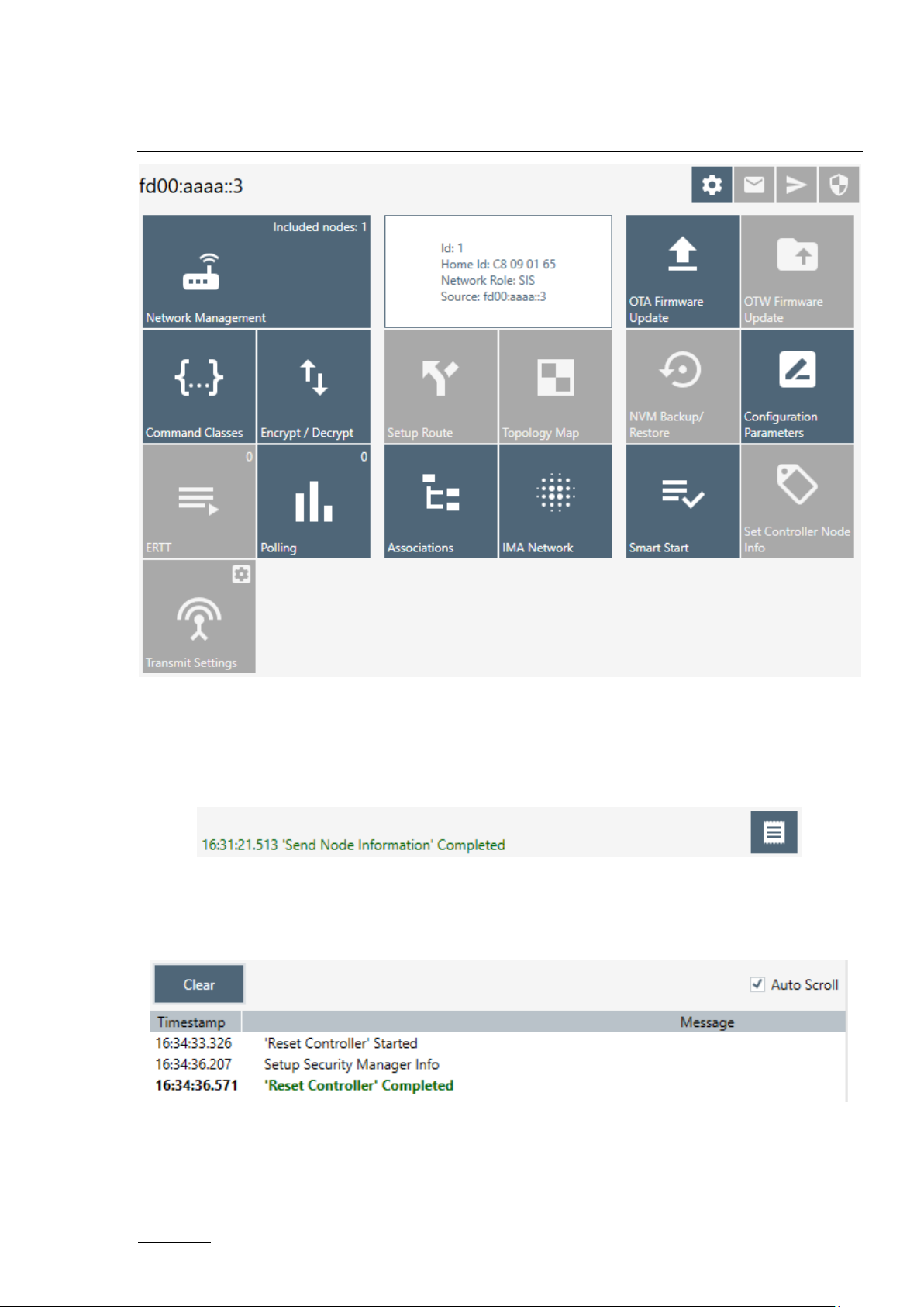
3.1.2 Content View
The Content View consists of command buttons and one Information item:
Network Management
Command Classes
Encrypt/Decrypt
ERTT
Figure 9. Security Extension Overrides
Page 21
INS13114-20 Z-Wave PC based Controller v5 User Guide 2020-12-01
silabs.com | Building a more connected world.
Page 12 of 80
Polling
Transmit Settings
Setup Route
Topology Map
Associations
IMA Network
Firmware Update (OTA)
Firmware Update (OTW)
Backup/Restore (NVM)
Configuration Parameters
Smart Start
Set Controller Node Information (active when the controller is selected and active)
Figure 10. Content View
Page 22
INS13114-20 Z-Wave PC based Controller v5 User Guide 2020-12-01
silabs.com | Building a more connected world.
Page 13 of 80
Figure 11. Content View with Z/IP Controller Connected
3.1.3 Log Bar
The Log bar contains information about the last action and a Show Log button.
Figure 12. Log Bar View
Pressing the Show Log button opens a new window with brief information about the action and its
time.
Figure 13. Log Window View
Page 23

INS13114-20 Z-Wave PC based Controller v5 User Guide 2020-12-01
silabs.com | Building a more connected world.
Page 14 of 80
Table 5. Log View Items
Menu item
Description
Clear
Clears log items.
Auto Scroll
Enables auto scroll.
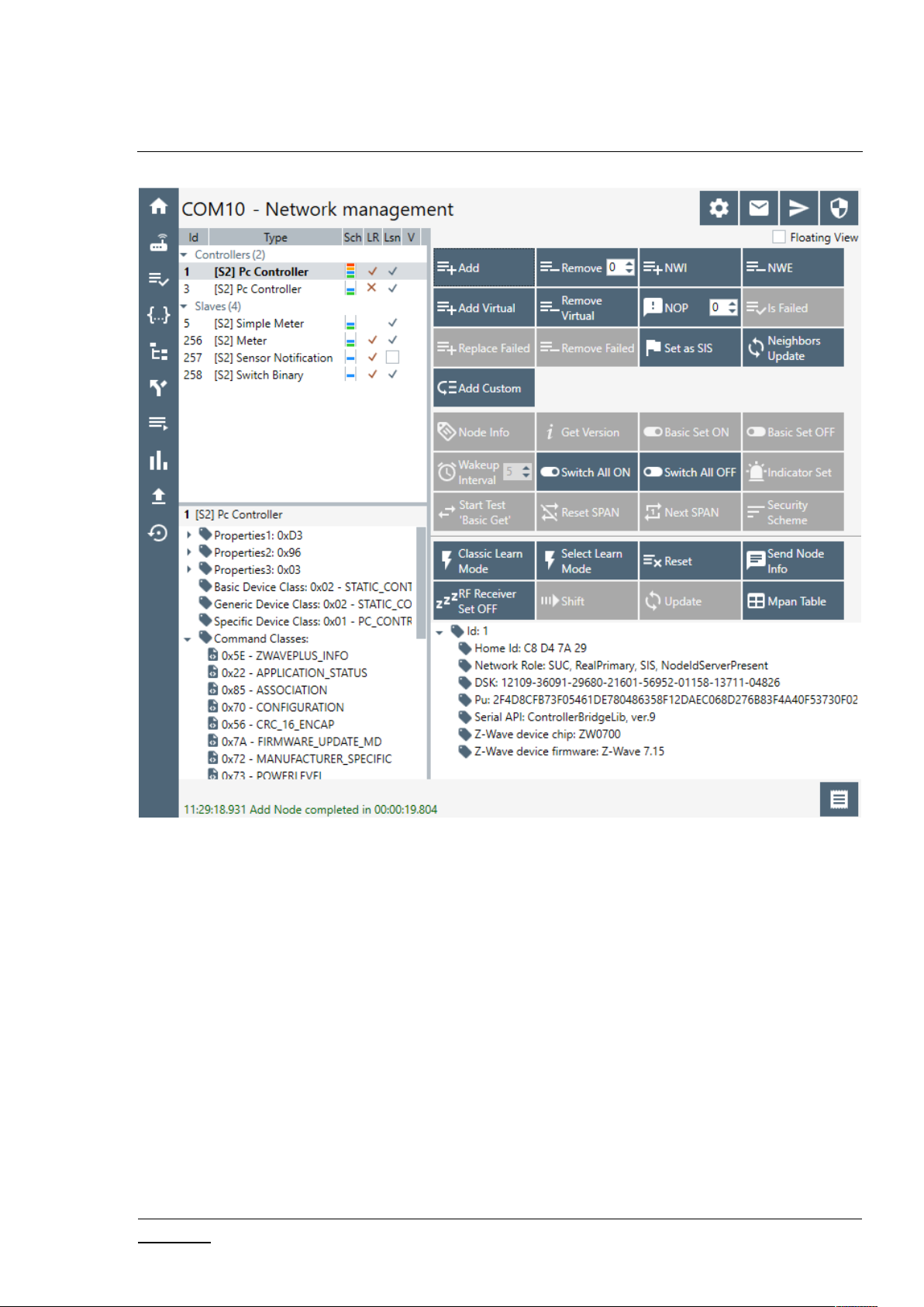
3.2 Network Management View
The Network Management View contains Node List and Node information for the selected node, Nodes
Actions, and Controller Actions. It is used for operations with nodes and basic controller actions.
If checked, the ‘Floating View’ checkbox Network Management View will be shown in the other
window.
Page 24
INS13114-20 Z-Wave PC based Controller v5 User Guide 2020-12-01
silabs.com | Building a more connected world.
Page 15 of 80
Figure 14. Network Management View
Page 25
INS13114-20 Z-Wave PC based Controller v5 User Guide 2020-12-01
silabs.com | Building a more connected world.
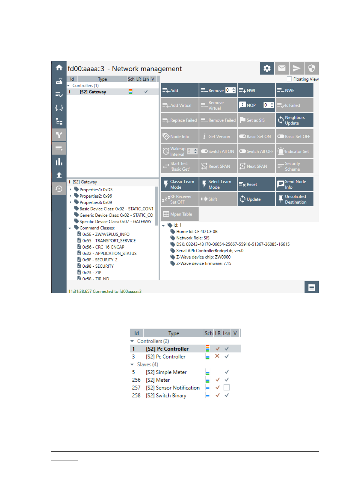
Page 16 of 80
Figure 15. Network Management View with Z/IP Controller Connected
3.2.1 Node List View
Figure 16. Nodes View
Used for view and selecting Nodes, contains next columns:
ID – shows the node numbers of all nodes in the network
Type – device type - shows description of the type of every node in the network
Page 26
INS13114-20 Z-Wave PC based Controller v5 User Guide 2020-12-01
silabs.com | Building a more connected world.
Page 17 of 80
Sch – security scheme granted
LR – long range capability
Lsn – checked if node is a listening node
V – checked if node is a virtual node
The current controller node is highlighted in bold font.
The button on the bottom line is to return to the ‘Network Management View’ from other views.
3.2.2 Node Information View
Figure 17. Node Information View
The Node Info section gives structured information about the selected node. For more information, see
the Z-Wave Device Class Specification documentation.
Navigate to the ‘Command Classes View’ by double clicking on an item from Command Classes or
Securely S0/S2 Supported Command Classes lists.
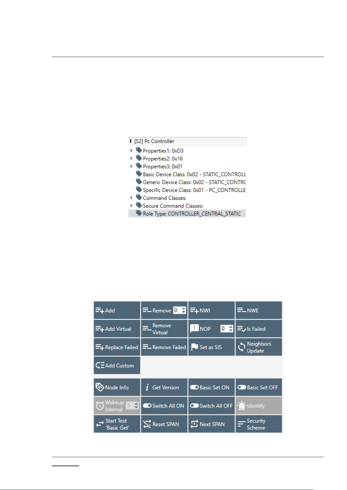
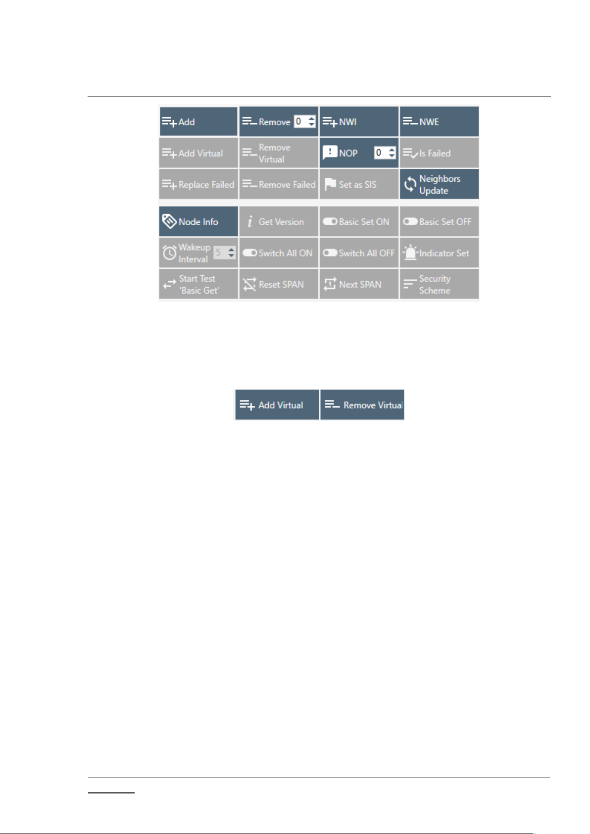
3.2.3 Nodes Actions View
Figure 18. Nodes Actions View
Page 27
INS13114-20 Z-Wave PC based Controller v5 User Guide 2020-12-01
silabs.com | Building a more connected world.
Page 18 of 80
Figure 19. Nodes Actions View when Z/IP Controller Connected
This view contains all available actions for a selected node. An action button is greyed out if the current
action is not available for a selected node.
Additional buttons for the Bridge Controller:
Figure 20. Bridge Controller Additional Actions
Page 28

INS13114-20 Z-Wave PC based Controller v5 User Guide 2020-12-01
silabs.com | Building a more connected world.
Page 19 of 80
Table 6. Node Actions View Items
Menu item
Description
Add
Start inclusion mode with default settings.
Remove
Removes a node.
NWI
(Network Wide Inclusion)
Network Wide Inclusion includes all nodes into network once
they have been reset and given power.
NWE
(Network Wide Exclusion)
Network Wide Exclusion excludes all nodes from network once
they have been reset and given power.
Add Virtual
Adds a virtual node for the Bridge Controller.
Remove Virtual
Removes a virtual node from Bridge Controller.
NOP
(Send NOP)
‘No Operation’ to send a frame not carrying any functional info
to a node.
Is Failed
Sends a Failure signal to a node.
Replace failed
Replaces a failed node.
Remove Failed
Removes a failed node.
Set SIS
Sets the “Set SIS” command to the selected Controller.
Neighbor Update
(Request Node Neighbor
Update)
Gets the neighbors from the specified node.
Add Custom
Add node using custom settings.
Node Info
Requests Node information from a node.
Version Get
Sends Version Get command to the selected node.
Basic Set On
Sends the BASIC SET ON command to Switch a selected node(s)
ON.
Basic Set Off
Sends the BASIC SET OFF command to Switch a selected
node(s) OFF.
Page 29

INS13114-20 Z-Wave PC based Controller v5 User Guide 2020-12-01
silabs.com | Building a more connected world.
Page 20 of 80
Wake Up Interval
Sets up the Wake-Up Interval for a non-listening node.
Switch All On
Switches all nodes in the network ON.
Switch All Off
Switches all nodes in the network OFF.
Start Basic Test/ Stop Basic Test
Starts and stops the basic test functionality to the selected
item.
Node Settings
Opens a pop-up with following actions for selected node ‘Reset
SPAN’, ‘Next SPAN’, ‘Security Scheme’.
Reset SPAN
Clears SPAN table for selected node.
Next SPAN
Rolls SPAN record one time on each click for selected node.
Security Scheme
Sets active security scheme for selected node.
Add Node Custom dialog:
Figure 21. Add Custom
Page 30

INS13114-20 Z-Wave PC based Controller v5 User Guide 2020-12-01
silabs.com | Building a more connected world.
Page 21 of 80
3.2.4 Controller View
The Controller view includes Network Role Option, Controller Actions, and Controller Information
sections. This view is used for operations with controllers.
Select the Controller learn modes dialog:
Figure 22. Controller View
Figure 23. Z/IP Controller View
Figure 24. Select Learn Mode
Page 31

INS13114-20 Z-Wave PC based Controller v5 User Guide 2020-12-01
silabs.com | Building a more connected world.
Page 22 of 80
Additional button for the Bridge Controller:
Menu item
Description
Learn Mode
(Start Learn Mode)
Starts classic learn mode for the controller if it is needed to include it in
another controller’s network.
Select Learn Mode
Opens Select learn mode dialog.
Reset
Resets a controller.
Send Node Info
Broadcasts node info from controller.
RF Receiver Set OFF
Disables radio transmission on connected device. Auto enables when send
operation is initiated.
Set Node Info
Changes node information for controller.
Shift
Shifts the primary role to another controller in the network.
Update
(Request Update)
An Inclusion controller can request network updates from a SIS.
MPAN Table
Modifies an existing MPAN table in PC Controller.
Unsolicited Destination
Gets and sets unsolicited destination for Z/IP Gateway.
Figure 25. Bridge Controller Additional Action
The Controller view has the following actions:
Table 7. Controller Actions View Items
The Network Role Option section has controls to assign the role of the SC in the network:
SIS – Static Update Controller with ID server
None
Page 32

INS13114-20 Z-Wave PC based Controller v5 User Guide 2020-12-01
silabs.com | Building a more connected world.
Page 23 of 80
General information regarding the SC is displayed in the Controller Information section in the following
Section
Description
Controller ID
Displays the node ID of the PC-based SC.
Controller Home ID
Displays the current Home ID of the PC-based SC.
Controller Network
Role
Displays the PC-based SC network role.
Serial Port
Displays the serial port in use.
Source
Displays connection address (for Z/IP Controller).
DSK
Displays DSK of current controller.
Z/IP application
version
Displays current firmware version of Z/IP Gateway application.
items:
Table 8. General Information View Items
Mpan Table View
Call from the Controller View by clicking on ‘Mpan Table’ button opens a new window ‘Mpan Table
configurations’. Group ID, Owner ID, MOS state, MPAN, Node IDs list will be listed for each record in the
table after pressing “Load MPANs” button.
Figure 26. Mpan Table View
Page 33

INS13114-20 Z-Wave PC based Controller v5 User Guide 2020-12-01
silabs.com | Building a more connected world.
Page 24 of 80
Table 9. MPAN View Items
Buttons
Description
Load MPANs
Retrieves current state of Mpan table of PC Controller.
Clear
Deletes all entries in Mpan table.
Add/Update
Create new or updates data in Mpan table for entered Group id and Owner
ID. If data wasn’t present in the table, a new record will be created.
Remove
Removes the selected item from Mpan table.
Next MPAN
Calculates next MPAN for selected item in table.
Button
Description
Start/Stop
Set current unsolicited destination state.
Secondary enable
Toggle
Display and change secondary port state.
Apply
Set custom settings and sends unsolicited destination set command to Z/IP
Gateway.
Close
Closes the window.
Unsolicited destination
Call from the Controller View by clicking on ‘Unsolicited Destination’ button opens a new window ‘Z/IP
Unsolicited Destination’. Pressing the “Start/Stop” button will update the unsolicited destination
address on the Z/IP Gateway and restart an unsolicited listener in the PC Controller for a selected port.
Figure 27. Unsolicited Destination View
Table 10. Unsolicited View Items
Page 34

INS13114-20 Z-Wave PC based Controller v5 User Guide 2020-12-01
silabs.com | Building a more connected world.
Page 25 of 80
Button “Apply” triggers the “Unsolicited address” view from text input to drop down list selector with
list of all IP Addresses of the current machine.
3.3 Associations View
The Associations view has a Nodes List View, Node Information View, and Association Actions View. It is
used to set up associations between nodes.
Figure 28. Associations View
Page 35

INS13114-20 Z-Wave PC based Controller v5 User Guide 2020-12-01
silabs.com | Building a more connected world.
Page 26 of 80
Table 11. Association View Items
Menu item
Description
Create
Creates an association between selected nodes.
Remove
Removes a selected association.
Get Groups Info
Returns groups for selected nodes in the association's tree view with
information about group’s Profile and group’s supported command
classes.
Get Nodes
Return nodes for a selected group in the association's tree view.
The Associations View shows a tree of available source nodes that support the Association command
class, e.g., Binary sensor.
The Groups node shows the association groups that can be or have been created, information based on
Association Group Info command class, and profile and supported command classes for each group.
The “Assign Return Routes” checkbox is to define whether the Controller should assign return routes
together with setting the association.
3.4 Command Class View
The Command Class view is used to send a specified command class to a selected node with
parameters.
Command Classes View can be shown in a separate window when the Floating View is checked.
Page 36

INS13114-20 Z-Wave PC based Controller v5 User Guide 2020-12-01
silabs.com | Building a more connected world.
Page 27 of 80
Figure 29. Command Classes View
Command Classes View consists of the following items:
1) Nodes and Node Info views (on the left)
2) Send Data History
3) Group of checkboxes for wrapping selected command with another (on the top)
4) Command selection view (in the middle, includes command class selection and send data text
box)
5) Send Data section: Send Data field – current payload and Drop-down list of expected
commands (if enabled)
6) Sending mode radio buttons and control buttons (on the bottom)
7) Security commands references
Page 37

INS13114-20 Z-Wave PC based Controller v5 User Guide 2020-12-01
silabs.com | Building a more connected world.
Page 28 of 80
Table 12. Send Data View Items
Item
Description
CRC16
Wraps the selected command with a CRC16 command.
Suppress Multicast Follow up
Disables follow up Singlecast frames after a multicast frame.
Force Multicast
Uses multicast even if only one frame is selected.
Supervision Get
Wraps the selected command with a Supervision command.
Session ID
Session ID will be present in the Supervision encapsulated
command. Can be set manually or auto incremented by
enabling the ‘Auto increment’ checkbox (set by default).
Multi-Channel
Enables multi-channel wrapping.
End Point (SRC)
Sets the Source End Point when a wrapping multi-channel is
enabled.
End Point (DST)
Sets the Destination End Point when a wrapping multi-channel
is enabled.
Bit Address
Sets the Bit Address flag for a Multi-Channel Command.
Command class
Shows the selected command class.
Command
Selects a command from the selected Command Class and
shows selected command from the ‘Select Command View’.
Select
Open the ‘Select command’ view (Figure 30) to choose a
command.
Send Data History
List of recently sent commands. A double-click on item
automatically inserts data in Send Data control and fills selected
command.
Send data
List of recently sent commands. A click on item automatically
inserts data in Send Data control.
Expect command
Shows a list of commands that is filtered by currently selected
Command Class control. PC Controller will wait for a node to
respond with selected command. Timeout for this expect
defined in ‘Send Data Settings’ view. When enabled ‘Send’
button changes its label to ‘Request’.
Page 38

INS13114-20 Z-Wave PC based Controller v5 User Guide 2020-12-01
silabs.com | Building a more connected world.
Page 29 of 80
Default
Radio button to set security mode to default (Secure for
securely included nodes, non-secure for normally included
nodes).
Secure
Radio button to enable force secure command sending.
Non-secure
Radio button to enable force non-secure command sending.
Broadcast
Radio button to enable force broadcast sending.
Serial API
Radio button to send bytes directly to Serial API of connected
controller device.
Reload XML
Reloads XML from the local machine if changes were made in it.
Send/Request
Button to send a command or request if enabled ‘Expect
command’ to a selected node.
Node Info
Gets the node information from a selected node.
Reset SPAN
Clears the SPAN table for a selected node.
Next SPAN
Rolls the SPAN record one time on each click for a selected
node.
Security Scheme
Sets the active security scheme for a selected node.
MPAN Table
Opens the MPAN settings dialog.
The Select Command view is used to show and select all available commands with information about a
selected node. This consist of the following:
List of Command classes and commands (on the left)
Information about a selected command (on the right)
Page 39

INS13114-20 Z-Wave PC based Controller v5 User Guide 2020-12-01
silabs.com | Building a more connected world.
Page 30 of 80
Figure 30. Select Command View
Item
Description
All Command Classes
Allows choosing all command classes and not only supported by device.
Ok
Confirms a selection.
Cancel
Closes a window without selection.
Table 13. Select Command View Items
3.5 Setup Route View
Setup Route View allows assigning or deleting routes between nodes.
Figure 31. Setup Route View
Page 40

INS13114-20 Z-Wave PC based Controller v5 User Guide 2020-12-01
silabs.com | Building a more connected world.
Page 31 of 80
Setups in the top of the view are change modes for assigning a route.
Item
Description
Return Route
Enables ‘Return Route’ mode.
Priority Return Route
Enables ‘Priority Return Route’ mode.
SUC Return Route
Enables ‘SUC Return Route’ mode.
Priority SUC Return
Route
Enables ‘Priority SUC Return Route’ mode.
Get/Set Priority Route
Enables ‘Get/Set Priority Route’ mode.
Priority Route
Repeaters array from route.
Route Speed
Selects Route Speed.
Get Priority Route
Gets a priority route for selected node.
Set Priority Route
Sets a priority route for selected node.
Assign
Assigns routes via selected nodes.
Delete
Deletes assigned routes for selected node.
Source Node list(left) and Destination Node list(right) show lists of source and destination nodes in a
routed network respectively.
Table 14. Setup Route View Items
Page 41

INS13114-20 Z-Wave PC based Controller v5 User Guide 2020-12-01
silabs.com | Building a more connected world.
Page 32 of 80
3.6 ERTT View
Item
Description
Test Iterations
Repeats the test selected number of times.
ERTT (Enhanced Reliability Test Tool) View allows configuring the test scenario and shows status of the
test running.
ERTT View itself consists of following items:
1) Nodes and Node Info views (on the left)
2) ERTT configuration view (in the middle)
Table 15. ERTT View Items
Figure 32. ERTT View
Page 42

INS13114-20 Z-Wave PC based Controller v5 User Guide 2020-12-01
silabs.com | Building a more connected world.
Page 33 of 80
Run forever
Repeats the test infinite times with 100 ms delay
between requests.
Low power
Send frames with low power when selected.
Test Mode
Sends basic set with a selected value by radio
buttons.
TX Controlled by Module
Enable TX mode to start test from device, only for
supported devices.
Stop on Error
Stops the test if error occurs.
Start/Stop
Starts or stops running test.
Retransmission
When checked, enables frame retransmission. Only
if supported TX Controlled by module.
3.7 Polling View
Item
Description
Start button
Runs the Polling for all nodes in the list.
Polling View allows enabling polling for all available nodes in the network.
Figure 33. Polling View
Table 16. Polling View Items
Page 43

INS13114-20 Z-Wave PC based Controller v5 User Guide 2020-12-01
silabs.com | Building a more connected world.
Page 34 of 80
Stop button
Stops the process.
Edit buttons
On list items allows setting Poll Time, sec. and Report Time, sec
parameters for polling.
Done button
Used to finish editing parameters and exit Edit mode.
3.8 Topology Map View
This view shows a graphical representation of the node network and access between.
Figure 34. Topology Map
The Topology Map view consists of:
The Graphical topology scheme itself
Node Type Colors section
Page 44

INS13114-20 Z-Wave PC based Controller v5 User Guide 2020-12-01
silabs.com | Building a more connected world.
Page 35 of 80
Table 17. Topology Map View Items
Item
Description
Graphical topology
scheme
Graphically represents the network scheme, showing the nodes of all types
differentiated through colorization, and the link statuses between the
Installer controller and slave nodes.
Reload Topology
Reloads the topology.
Node Type Colors
Node Type Colors is a list of node types with colors assigned for graphical representation on the
Topology Scheme. It is possible to select a special color for each node type.
Page 45

INS13114-20 Z-Wave PC based Controller v5 User Guide 2020-12-01
silabs.com | Building a more connected world.
Page 36 of 80
3.9 IMA Network View
The IMA Network view has a Network Actions View Nodes, Nodes View, IMA Details View, and Network
Layout Properties View. Installation and Maintenance Application (IMA) is designed to perform analysis
of network health.
Figure 35. IMA Network View
Page 46

INS13114-20 Z-Wave PC based Controller v5 User Guide 2020-12-01
silabs.com | Building a more connected world.
Page 37 of 80
Table 18. IMA Network View Items
Menu item
Description
Network Health
Performs an algorithm for gathering measurements to calculate the
Network Health Value. These measurements are: RC, PER, NB, LWRdB,
and LWRRSSI.
Request Node Info
Sends the Node information get command.
Get Version
Sends the Version get command.
Ping Node(s)
Sends the NOP command and waits for Ack from the node.
Reload Routing Info
Executes the Get routing information command and rebuilds the
neighbors list.
Rediscovery
Sends Get Nodes In Range command.
Src / Dest
Specifies the source and destination node for commands with source
and destination arguments.
Power Level Test
Performs a power level test (only for selected nodes Src and Dest).
The Nodes View shows the nodes in the network and controller. It also shows the neighbor’s
connections of selected node and, after the Network health completed, the connections between
nodes. Each node can be moved on canvas. Multiple nodes can be selected.
To move the canvas use ALT + drag.
To zoom in/out the canvas use CTRL + scroll.
Page 47

INS13114-20 Z-Wave PC based Controller v5 User Guide 2020-12-01
silabs.com | Building a more connected world.
Page 38 of 80
The IMA Details View contains detailed information about each step of the Network Health algorithm.
Menu item
Description
Details
Shows the list of recommended actions according to the Network Health
status. See Figure 36.
Legend
Opens a popup window with information about the measurements. See
Figure 37.
Empty entries show that this measurement cannot be calculated for a selected node.
Table 19. IMA Details View Items
Figure 36. IMA Network Health Status Description (Details)
Page 48

INS13114-20 Z-Wave PC based Controller v5 User Guide 2020-12-01
silabs.com | Building a more connected world.
Page 39 of 80
Figure 37. IMA Network Health Value Description (Legend)
Page 49

INS13114-20 Z-Wave PC based Controller v5 User Guide 2020-12-01
silabs.com | Building a more connected world.
Page 40 of 80
The Network Layout Properties View allows changing the view of the Nodes, its scale, and background.
Menu item
Description
Zoom
Changes the scale of the canvas.
Image
Opens a dialog window to choose the picture background for the canvas.
Fill
A color of filling can be chosen when the checkbox is activated.
Legend
Opens a popup window with information about the elements shown on
Nodes View. See Figure 38.
Figure 38. IMA Nodes View Description (Legend)
Table 20. IMA Nodes View Items
3.10 Encrypt/Decrypt View
Encrypt/Decrypt Message View allows to either Encrypt or Decrypt message.
S0 Tab to use Security S0 encrypt algorithms
Page 50

INS13114-20 Z-Wave PC based Controller v5 User Guide 2020-12-01
silabs.com | Building a more connected world.
Page 41 of 80
Figure 39. Encrypt/Decrypt View S0 Tab
Item
Description
Use Current
Inserts the current network key to a field from the security scheme.
Decrypt
Decrypts the message set in the Encrypted message with parameters
from input fields.
Encrypt
Encrypts the message set in the Decrypted message with parameters
from input fields.
Table 21. Encrypt/Decrypt S0 View Items
S2 Tab to use Security S2 encrypt algorithms
Figure 40. Encrypt/Decrypt View S2 Tab
Page 51

INS13114-20 Z-Wave PC based Controller v5 User Guide 2020-12-01
silabs.com | Building a more connected world.
Page 42 of 80
Table 22. Encrypt/Decrypt S2 View Items
Item
Description
Decrypt
Decrypts the message set in the Encrypted message with parameters from
input fields.
Encrypt
Encrypts the message set in the Decrypted message with parameters from
input fields.
3.11 Firmware Update (OTA) View
Firmware Update (Over the Air) View provides functionality to update devices over the air.
Figure 41. Firmware Update (OTA) View
Firmware Update View consists of the following items:
Nodes and Node Info views (on the left)
Firmware configuration view (in the middle)
Page 52

INS13114-20 Z-Wave PC based Controller v5 User Guide 2020-12-01
silabs.com | Building a more connected world.
Page 43 of 80
Table 23. Firmware Update OTA View Items
Item
Description
Get
Gets the information about the current firmware of a selected
node.
File selection
Allows selecting a file with *.hex or any other extension.
Update
Starts the update process on a selected node.
Activate
Sends Firmware Update Activation Set command to start the
delayed activation process. Button available only for Firmware
Update MD Command Class Version 4.
Page 53

INS13114-20 Z-Wave PC based Controller v5 User Guide 2020-12-01
silabs.com | Building a more connected world.
Page 44 of 80
3.12 Firmware Update (OTW) View
Firmware Update (Over the Wire) View provides functionality to update devices that are connected to
the PC. It opens a file dialog window to choose the update file.
Figure 42. File Dialog View
3.13 Backup/Restore NVM
NVM (Non-volatile Memory) Backup/Restore View provides functionality to save and upload nonvolatile memory content of the device.
Figure 43. NVM Backup/Restore View
Page 54

INS13114-20 Z-Wave PC based Controller v5 User Guide 2020-12-01
silabs.com | Building a more connected world.
Page 45 of 80
Table 24. NVM Backup/Restore View Items
Item
Description
… (Save As)
Selects a destination file to save data.
Backup
Starts backup to file.
… (Open)
Selects a source file of NVM.
Restore
Starts a restore file to device.
Item
Description
Get List
Gets list of configuration parameters for a selected controller.
Set
Sets configuration parameters.
3.14 Configuration Parameters
Configuration Parameters View to manage node settings using the Configuration Command Class
Figure 44. Configuration Parameters View
Table 25. Configuration Parameters View Items
3.15 Smart Start View
Smart Start View contains a provisioning list of DSKs provided by the PC Controller and enables
managing it.
Page 55

INS13114-20 Z-Wave PC based Controller v5 User Guide 2020-12-01
silabs.com | Building a more connected world.
Page 46 of 80
Figure 45. Smart Start View
Figure 46. Z/IP Controller Connected Smart Start View
Page 56

INS13114-20 Z-Wave PC based Controller v5 User Guide 2020-12-01
silabs.com | Building a more connected world.
Page 47 of 80
Table 26. Smart Start View Items
Item
Description
Refresh List
Reloads the provisioning list.
Scan DSK
Open dialog which give opportunity to scan QR-Code using special
scanner or connected camera.
Import DSKs
Load provisioning list from special XML file.
Export DSKs
Save provisioning list to file.
Grant Schemes
Select which security schemes to be granted if requested
Node Options
Select which node options to be used during smart start inclusion
process. Only Long-range or only normal smart start requests will
be accepted depending on ‘Long Range’ node option.
Auto remove DSK on
Device Reset Locally
Notification
Option to enable/disable removing node included to network
using DSK from the provisioning list on receiving ‘Device Reset
Locally’ notification from it.
Add
Adds a new DSK to the provisioning list.
Updated
Change selected item from the provisioning list.
Remove
Removes the selected DSK from a provisioning list.
Remove All
Clears the provisioning list.
3.16 Set Node Information View
Set Node Information view allows to change PC Controller list of command classes for node
information, setup device options and Z-Wave Plus Info Report.
Page 57

INS13114-20 Z-Wave PC based Controller v5 User Guide 2020-12-01
silabs.com | Building a more connected world.
Page 48 of 80
Figure 47. Set Node Info View
Page 58

INS13114-20 Z-Wave PC based Controller v5 User Guide 2020-12-01
silabs.com | Building a more connected world.
Page 49 of 80
Table 27. Set Node Info View Items
Item
Description
Command Classes list
Select supported command classes for connected device, bold fold
highlights supported/controlled classes by application.
Default
Automatically set checkbox only for default command classes.
Clear
Clear selected items in the list.
Role Type
Select value for Z-Wave Plus Info Report Role Type.
Node Type
Select value for Z-Wave Plus Info Report Node Type.
Listening
Option to Enable/Disable is listening property.
Device Option
Select value for Basic Device Class in Application Node Info.
Generic
Select value for Generic Device Class in Application Node Info.
Specific
Select value for Specific Device Class in Application Node Info.
Set
Apply changes.
3.17 Transmit Settings View
Transmit Settings View provides functionality to adjust the TX power on Z-Wave 700 Controller devices.
Figure 48. Transmit Settings View
Page 59

INS13114-20 Z-Wave PC based Controller v5 User Guide 2020-12-01
silabs.com | Building a more connected world.
Page 50 of 80
Table 28. Transmit Settings View Items
Item
Description
Set ‘Tx Power Level’
Configure of default Tx Power level settings in deci dBm in range
from -100 to +130, where value 100 equal to 10 dBm, and values
greater than 100 are for test purposes.
Set ‘RF Region’
Configure of RF Region settings with selected item from the
“Region” combo box.
Set ‘LR Channel’
Configure Channel in use for Serial API Controllers only if Rf Region
is US_LR.
Page 60

INS13114-20 Z-Wave PC based Controller v5 User Guide 2020-12-01
silabs.com | Building a more connected world.
Page 51 of 80
4 FUNCTIONALITY
For each SC in the network, a separate instance of the PC-based Controller application must be started.
Note: For correct behavior of the Z/IP Gateway as SIS in network and for support of the Inclusion
controller command class, set up unsolicited destination. For more information, see Section 3.2.4.
The SC can be configured to one of the following controller types:
Primary SC
Secondary SC
Primary SC with SUC and node ID Server functionality (SIS)
Inclusion SC
Primary SC
When configured as primary, the SC can be used to include/exclude nodes in the Z-Wave network. The
primary SC will automatically update an SUC if present in the Z-Wave network. Only one primary
controller is allowed in the Z-Wave network.
Secondary SC
When configured as secondary, the SC cannot include/exclude nodes in the Z-Wave network. Several
secondary controllers are allowed in the Z-Wave network.
Primary SC with SUC and node ID Server functionality (SIS)
The SIS enables other controllers to include/exclude nodes in the network on its behalf. The SIS is the
primary controller in the network because it has the latest update of the network topology and
capability to include/exclude nodes in the network. When including additional controllers to the
network, they become inclusion controllers because they have can include/exclude nodes in the
network on behalf of the SIS. The SIS cannot shift its primary role to other controllers in the network.
To read more about SIS functionality, see reference [2].
Inclusion SC
The inclusion SC can include/exclude nodes in the network on behalf of the SIS. The inclusion SC’s
network topology is dated from the last time a node was included or it requested a network update
from the SIS and therefore it can’t be classified as a primary controller.
Page 61

INS13114-20 Z-Wave PC based Controller v5 User Guide 2020-12-01
silabs.com | Building a more connected world.
Page 52 of 80
4.1 The SC Properties
Depending on the functionality required in the network, the PC-based Controller (SC and BC) can shift
roles to obtain the desired functionality.
Primary
If the SC is the first node in a network, it will automatically be configured to act as a primary controller.
Secondary
If the SC is not the first node in a network, it will automatically be configured to act as a secondary
controller.
SIS
It is possible to set the Network Role Option by clicking Set as SIS command.
The table below shows which functionality is available for the PC-based SC depending on the
configuration on the controller.
Page 62

INS13114-20 Z-Wave PC based Controller v5 User Guide 2020-12-01
silabs.com | Building a more connected world.
Page 53 of 80
Table 29. Overview of the Static Controller Properties
Primary
Inclusion
SIS
Secondary
Node:
Add Node
XXX
-
Add Node with DSK
XXX
-
Remove Node
XXX
-
Network Wide Inclusion
XXX
-
Network Wide Exclusion
XXX
-
NOPXXXX
Mark Node as Failed
XXX
X
Replace Failed Node
XXX
-
Remove Failed Node
XXX
-
Set as SIS
XXX
-
Neighbors Update
XXX
X
Request Node Info
XXX
X
Basic Set On
XXX
X
Basic Set Off
XXX
X
Set wake Up Interval
X--
-
Switch All On
XXX
X
Switch All Off
XXX
X
IdentifyXXXX
Start Test ‘Basic Get’
XXX
X
Change Security Scheme
XXX
X
Reset SPAN
XXX
X
Controller:
Receive Information
XX-
X
Send Information
XXX
-
Create New Primary
---
-
Controller Shift
X--
-
Reset Controller
XXX
X
Request Update
-X-
-
Command Class:
SendXXXX
Association:
Create Association
XXX
X
Page 63

INS13114-20 Z-Wave PC based Controller v5 User Guide 2020-12-01
silabs.com | Building a more connected world.
Page 54 of 80
Remove Association
XXX
X
Get Associations
XXX
X
Setup Route:
Assign Route
XXX
X
Delete Route
XXX
X
Get Priority Route
XXX
X
Set Priority Route
XXX
X
General:
All OnXXXX
All OffXXXX
AbortXXXX
OTA Firmware Update
XXX
X
OTA Firmware Update
XXX
X
IMA Network
XXX
X
NWM Backup/Restore
XXX
X
Configure Parameters
XXX
X
Smart Start
XXX
-
Set Node Information (Reset State)
XXX
-
Transmit Settings (ZW070x only)
XXX
X
4.2 Node View
4.2.1 How to Add a Node
PC-based SC is Primary / Inclusion / SIS
To add a node to the Z-Wave network, activate the button ‘Add’ in the 'Network Management' view.
When activating this button, the Status popup message will display ‘Press shortly the pushbutton on the
node to be included in the network’. Select the node that should be added to the Z-Wave network by
activating the node’s button. During the inclusion process, the node must be located at its final
position, so that it can obtain the correct neighbors within its range. If the operation was successful,
information regarding the node type will be displayed in the node list. The PC-based controller reduces
the RF output power during the inclusion process, which can cause range problems because it is static,
i.e., located in a fixed position. It is, therefore, recommended that one use a portable controller as
primary for adding new nodes to the Z-Wave network.
To include Long Range devices, use Smart Start inclusion only, described in 4.16. For Long Range
included devices, the PC Controller uses Long Range Network Keys for Security Schemes Access and
Authenticated.
Page 64

INS13114-20 Z-Wave PC based Controller v5 User Guide 2020-12-01
silabs.com | Building a more connected world.
Page 55 of 80
The Default Inclusion process in Add Node command combines inside protocol inclusion part, auto
setup SIS in a network according to Role Type specifications, security bootstrap, and setup default
lifeline (route, association and wakeup if supported by joining node). To manage the inclusion process,
use: Add Node Custom.
Note: For the correct behavior of Z/IP Gateway as SIS in network and for support of the Inclusion
controller command class, set up unsolicited destination. For more information, see Section 3.2.4.
Figure 49. Popup Message After Pressing 'Add' Button
A secure S2 node asks for network keys during inclusion. The PC Controller application shows the
following dialog:
Figure 50. Network Keys Request
The secure inclusion flow will be cancelled if the user presses the Cancel button. As a result, the node
will be included non-securely.
The Device-Specific Key (DSK) may be required during a secure S2 node inclusion. The PC Controller
application shows the next dialog where the user may input text as decimal or hex value using check
box or scan it from a QR Code – button “QR Code”:
Figure 51. Enter DSK Dialog
Page 65

INS13114-20 Z-Wave PC based Controller v5 User Guide 2020-12-01
silabs.com | Building a more connected world.
Page 56 of 80
The secure inclusion flow will be cancelled if the user presses the Cancel button. As a result, the node
will be included non-securely.
PC-based Controller is Secondary
It is not possible to add nodes to the Z-Wave network.
4.2.2 How to Add Multichannel Node with EndPoints
The process of inclusion a Multichannel node is the same as for other nodes. When adding the node
with supported command class, Multi Channel PC Controller will additionally ask End Points to list and
indicate the capability for each.
Figure 52. Multi Channel Node with End Points View
4.2.3 How to Remove a Node
PC-based SC is Primary / Inclusion / SIS
To remove a node from the Z-Wave network, select the node in the node list and activate the button
‘Remove’. After activating the button, the Status popup message will display ‘Press shortly the
pushbutton on the node to be excluded from the network’. If this operation was completed
successfully, the node and its information will be removed from the node list. The PC-based Controller
reduces the RF output power during the exclusion process, which can cause range problems because it
is static, i.e., located in a fixed position. It is, therefore, recommended one use a portable controller as
primary to remove a node when having range problems.
Figure 53. Popup Message After Pressing 'Remove' Button
PC-based Controller is Secondary
It is not possible to remove nodes from the Z-Wave network.
4.2.4 Network Wide Inclusion
The NWI button on the PC Controller results in the PC Controller calling AddNodeToNetwork and, after
a successful inclusion, the AddNodeToNetwork is called again.
Page 66

INS13114-20 Z-Wave PC based Controller v5 User Guide 2020-12-01
silabs.com | Building a more connected world.
Page 57 of 80
To start mass inclusion of nodes, press the Network Wide Inclusion button. The dialog will appear with
the text: “Controller is waiting for the node information… Press shortly the pushbutton on the node to
be included in the network.”
Once all nodes have been included, press the ‘Abort Operation’ button to stop the NWI.
4.2.5 Network Wide Exclusion
Pressing the NWE button on the PC Controller calls RemoveNodeFormNetwork and, after a successful
exclusion, the RemoveNodeFormNetwork is called again.
To start the Network Wide Exclusion nodes from the controller, press the NWE button and press the
pushbutton on each node to exclude it.
4.2.6 Send NOP
This button is used to send a NOP frame to a selected node. Enter the Node ID of the target node in the
text box and press the ‘NOP’ button.
4.2.7 How to Send a Failure Signal to a Node
If a node is corrupt and does not respond to commands, it can be marked as failed, and either replaced
or removed.
Push “Is Failed” button for the selected node. The node will be marked in the list as failed (in red font).
4.2.8 How to Replace a Failed Node
PC-based SC is Primary / Inclusion / SIS
A non-responding node can be replaced by another node from the node list in the Z-Wave network by
activating the button ‘Replace Failed’. The following message will appear: “Replacing the nonresponding node… Press shortly the pushbutton on the replacement node to be used instead of the
failed one”. If the operation was successful, the failed node is removed, and the other node will take
the node ID of the failed node. Association setup in the failed node will be lost and must be
reprogrammed.
PC-based SC is Secondary
It is not possible to replace a failing node.
4.2.9 How to Remove a Failing Node
PC-based SC is Primary / Inclusion / SIS
A non-responding node can be removed from the Z-Wave network by activating the button ‘Remove
Failed’. If the operation was successful, the node and its information will be removed from the node list.
Responding nodes cannot be removed.
PC-based SC is Secondary
Page 67

INS13114-20 Z-Wave PC based Controller v5 User Guide 2020-12-01
silabs.com | Building a more connected world.
Page 58 of 80
It is not possible to remove a failed node.
4.2.10 Set SIS
It is possible to assign a SIS network role to the selected controller by sending the
CmdZWaveSetSucNodeId to it. To perform this operation, press on 'Set as SIS' button on the 'Network
Management View'.
It is possible to set only one SIS in the network. If trying to set more than one SIS, the PC Controller will
show the following warning.
Figure 54. Set SIS Warning Message
4.2.11 Request Node Neighbors Update
It is possible to send the Find Nodes in Range command to the selected node.
4.2.12 Node Info
When the Node Info button is pressed, the PC Controller application sends a REQUEST NODE INFO
command to the selected node.
For Multichannel nodes, the application will update End Points list and capability for each.
4.2.13 Version Get
Send Version Get command to the selected node(s).
4.2.14 Switching a Node or a Subset of Nodes on and off
Basic Set On
Activate the button ‘On’ to send the ‘On’ command to the selected node(s).
Basic Set Off
Activate the button ‘Off’ to send the ‘Off’ command to the selected node(s).
Page 68

INS13114-20 Z-Wave PC based Controller v5 User Guide 2020-12-01
silabs.com | Building a more connected world.
Page 59 of 80
4.2.15 Set Wake-Up Interval
It is possible to set the wake-up interval for a non-listening node. Enter the desired wake up interval (in
minutes) into the textbox and press the ‘Set Wake Up Interval’ button. The WAKE_UP_INTERVAL_SET
command will be queued in the application memory and sent to the non-listening node the next time it
wakes up.
4.2.16 ‘Switch All On’ Command
To send an ‘All on’ command to all nodes in the Z-Wave network, press the button ‘Switch All On’.
4.2.17 ‘Switch All Off’ Command
To send an ‘All off’ command to all nodes in the Z-Wave network, press the button ‘Switch All Off’.
4.2.18 ‘Identify’ Command
To send an “Indicator Set” command to selected node if it supports this command class.
4.2.19 Start/Stop Basic Test
This option is for stress test purposes. When the ‘Start Basic Test’ button is pressed, the PC Controller
sends a BASIC GET command to the selected node(s). After a BASIC REPORT is received from the node in
the queue, the next BASIC GET command is sent either to the same node (if it is the only node selected
for operation), or to the next node in the list. If the node does not respond, the controller sends the
next command or moves to the next node after a timeout of 10 seconds.
Node settings contains following actions with Security:
4.2.20 Reset SPAN
To clear Singlecast Pre-Agreed Nonce table for selected node.
4.2.21 Next SPAN
To roll Singlecast Pre-Agreed Nonce entry for selected node.
4.2.22 Security Scheme
The controller can change the security scheme for communication with a selected node.
Figure 55. Select Security Scheme Dialog
Page 69

INS13114-20 Z-Wave PC based Controller v5 User Guide 2020-12-01
silabs.com | Building a more connected world.
Page 60 of 80
4.3 Controller View
When including a PC-based SC to a network, activate the ‘Add’ button on the primary controller, then
activate the ‘Learn Mode’ button on the second PC-based SC (the sequence of these two steps is not
vital). This will include the SC into the Z-Wave network and transfer the complete network topology.
Furthermore, it is possible to update the network topology in an existing secondary controller.
If the replication went successfully, the second PC-based SC’s functionality depends on the selected
option button:
If ‘SIS’ is chosen, and one does not already exist in the network, the SC will become the SIS in the
network. If a SIS is already present, the SC will become an Inclusion controller.
If ‘None’ is chosen, then SC will become a secondary or inclusion controller.
PC-based SC is Inclusion / SIS / Secondary
It is not possible to shift the primary role from the PC-based SC.
4.3.1 Reset Controller
To reset the PC-based SC, activate the ‘Reset’ button. See also paragraph 4.2.3 to learn how to exclude
nodes from the network.
4.3.2 Send Node Info
Send the broadcast node information from the controller.
4.3.3 Controller Shift
PC-based SC is Primary
To shift the primary role from the PC-based SC to another controller in the network, activate the ‘Learn
Mode’ button within the controller to be made primary, and the ‘Shift’ button within the second
controller interface. The second PC-based SC will now become Secondary and the first one will become
Primary.
4.3.4 Request Update of PC-based SC
PC-based SC is Primary / SIS / Secondary
It is not possible to request the network topology update from another controller.
PC-based SC is Inclusion
The PC-based SC can request network topology updates from a SIS by pressing the ‘Update’ button.
Page 70

INS13114-20 Z-Wave PC based Controller v5 User Guide 2020-12-01
silabs.com | Building a more connected world.
Page 61 of 80
4.4 Command Class View
Open the 'Command Class ' view to send specific command classes to nodes.
Select the node ID to receive the command from the node list.
To select a command class and command, click on the button ’Select’. ‘Select Command’ view will only
contain those commands that are supported by the selected nodes; however, it is possible to show all
command classes by enabling of ‘All Command Classes’ check-box. Some commands require setting a
value, e.g., Value. In this case, additional value fields will appear below with their names. All selected
and entered values will be shown in HEX string in the Send Data text block. This text block allows
changing manually Send data to send.
Finally, send the frame by activating the button ‘Send’.
4.5 Association View
Open the 'Associations' view to configure associations between nodes.
Add any nodes that support the Association command class, e.g., Binary sensor.
To view the current association groups of a selected node, press the button 'Get Groups Info'. To get all
nodes in the selected group, press 'Get Nodes' button.
4.5.1 Create Association
Select a node from Nodes List to associate with the node that supports the Association command class
in Association tree, Select Group, and click the ‘Create’ button. The node ID will appear in the
appropriate group.
4.5.2 Remove Association
Select the node to be removed from the association in the Groups list and press ‘Remove’.
4.6 Setup Route View
Open the ‘Setup Route' view to assign return routes between the two nodes in the network.
4.6.1 Assign a Route
The PC-based SC supports assigning a route between, e.g., a Binary Sensor, and any other node.
Assigning a route specifies how the binary sensor can communicate with the node. To assign a route,
select first a source and a destination node. The source node can be any node based on the routing
slave library while destination node can be any node that is always in listening mode. Activate ‘Assign’
button to generate a route between the two nodes. For a binary battery sensor, the route assignment
will be executed next time it wakes up. Until then, the request is queued in the PC-based Controller.
Page 71

INS13114-20 Z-Wave PC based Controller v5 User Guide 2020-12-01
silabs.com | Building a more connected world.
Page 62 of 80
4.6.2 Delete a Route
To delete routes in a node, press the ‘Delete’ button. All routes assigned to the source node will be
deleted. The new routing can be built either automatically or manually.
For a binary battery sensor, the route deletion will be executed next time it wakes up. Until then, the
request is queued in the PC-based Controller.
4.7 Security Test Schema View
In Z-Wave Security PC Controller, Security Test Schema functionality is available to test secure networks
for failures in case of device malfunctioning with using Security or Security version 2 Command Classes.
With this feature, it is possible to simulate different malfunctions of a Security PC Controller. This is
needed to test the proper functioning of other devices in the network.
To use this feature, the “Enable Security Test Schema” checkbox must be checked.
'Use Permanent Network Key' checkbox allows overriding generated by the controller Network Key. It
will use a specified Network Key for all operations after pressing “OK” or “Apply” button.
The testing Controller in Security version 0 can be configured either as the Including Controller or as the
Included Node. The corresponding options for an Including Controller or Included Node are present
dependent on the selection. All changes will be applied after pressing “OK” or “Apply” button.
The testing Controller in Security version 2 can be configured by using security parameters, messages,
and extensions overrides. All changes will be applied after pressing “OK” or “Apply” button.
Save Security Keys to Storage is used to generate file with network keys to load it from Zniffer
Application.
4.7.1 Test S2 Parameters Overrides
The “Test Span S2” field is used to encrypt S2 Message Encapsulation with a specific SPAN. It will ignore
Receivers Entropy input that is sent with the S2 Nonce Report.
The “Test Sender Entropy Input S2” field is used to substitute the SPAN extension value in the S2
Message Encapsulation in response to the S2 Nonce Report.
“Test Secret Key S2” – replaces current secret key of the S2 keypair. The DSK value will be calculated
based on the secret key.
The “Test Sequence Number S2” is used to override the S2 Message Encapsulation’s Sequence Number
property with a specific value.
The “Test Reserved field S2” is used to override the S2 Message Encapsulation’s Reserved property with
a specific value.
Page 72

INS13114-20 Z-Wave PC based Controller v5 User Guide 2020-12-01
silabs.com | Building a more connected world.
Page 63 of 80
4.7.2 Test S2 Messages Overrides
The “Test Frame” list contains all frames that are normally sent during the S2 inclusion. Therefore, the
user is allowed to interfere with the inclusion process with custom frames. Click the corresponding
checkbox to activate the parameter override and specify a new value. If the parameter override is not
active, the PC Controller will use a valid specific frame parameter value.
“Command” field is used to substitute the selected “Test Frame” with any command that is entered.
When enabled, the “Delay” field will postpone sending the selected “Test Frame” for a specified
amount of time.
“Is Multicast” field allows sending the “Test Frame” as multicast or singlecast.
“Is Broadcast” field allows sending the “Test Frame” as broadcast or singlecast.
“Is Encrypted” checkbox allows force sending the frame encrypted or force sending the message
unencrypted.
“Network Key” field is used to encrypt the selected “Test Frame” with specified bytes. It will only be
used if the ‘Is Encrypted’ checkbox is enabled and set.
“Is Temp Network Key” field is used to encrypt the selected “Test Frame” using a temporary expansion
algorithm. It will only be used if the ‘Is Encrypted’ checkbox is enabled and set. It will also use the
“Network Key” value as a security key to obtain the temporary key.
Example 1: The user wants to substitute the KEX Report (Echo) with the KEX Report frame that is
unencrypted, delayed for 2 seconds and with Echo flag set to 0.
KEX Report (Echo) test frame should be configured on the including controller. The following screenshot
shows all necessary properties that should be set.
Figure 56. Test Frame Configuration for Example 1
Example 2: The user wants to substitute the “Network Key Verify S2 Unauthenticated” frame which will
not be delayed, command will be used default but should be encrypted with the custom temporary key.
The Network Key Verify test frame should be configured on the joining controller. The following
screenshot shows all necessary properties that should be set.
Page 73

INS13114-20 Z-Wave PC based Controller v5 User Guide 2020-12-01
silabs.com | Building a more connected world.
Page 64 of 80
Figure 57. Test Frame Configuration for Example 2
4.7.3 Test S2 Message Encapsulation Extensions Overrides
“Clean up existing extensions first” checkbox is used to delete all default extensions that should be
added in a normal flow. Note that this will take effect even if no test extension is specified deleting all
extensions of S2 messages.
Message type allows filtering which extensions will be changed within the S2 message encapsulation
frame:
Type “Singlecast All” means all S2 message encapsulation singlecast frames.
Type “Singlecast with SPAN” means all S2 message encapsulation singlecast frames containing
SPAN extension.
Type “Singlecast with MPAN” means all S2 message encapsulation singlecast frames containing
MPAN extension.
Type “Singlecast with MPAN Group” means all S2 message encapsulation singlecast frames
containing MGRP extension.
Type “Singlecast with MOS” means all S2 message encapsulation singlecast frames containing
MOS extension.
Type “Multicast All” means all S2 message encapsulation multicast frames.
Extension type allows selecting a specific extension to add to the filtered S2 message encapsulation
frame:
SPAN
MPAN
MGRP (MPAN Group)
Test (value=FF)
Applied Action value enables applying a set test extension to the next message encapsulation and
contains next:
“Add” add predefined extension, even if extension was not added by application.
“Add or Modify” remove extension filtered by extension type if it was added by the application,
add predefined extension.
“Modify If Exists” replaces extension filtered by extension type with predefined only if it was
added by application.
Page 74

INS13114-20 Z-Wave PC based Controller v5 User Guide 2020-12-01
silabs.com | Building a more connected world.
Page 65 of 80
“Delete” remove extensions which are matches to filter item if it was added by application.
Extension length is an auto-calculated field.
Extension value allows specifying the extension data.
Click the corresponding checkbox to activate a parameter override and specify a new value. If the
parameter override is not active, the PC Controller will use valid specific extension parameter value.
Extension parameters
“Is Encrypted” option allows overriding the selected extension encryption.
“More to follow” option allows changing “more to follow” parameter of the selected extension
if activated.
“Is Critical” option allows changing the “Critical” parameter of the selected extension if
activated.
“Number of usage” option allows limiting a number of filtered S2 message encapsulation
frames. After adding the extension with several usages, the active counter will be “0 of N”. To
reset the counter, select the frame and click the button “Set”. Remember to click “OK” or
“Apply” to make the new test settings active.
Examples:
1. Filter the message with a SPAN extension by message type <Singlecast with SPAN>:
a. Put override <Add>, < SPAN > extension type, <NEWSPAN> value – Resulting message
with SPAN and <NEWSPAN>.
b. Put override <Add Or Modify>, <SPAN> extension type, <NEWSPAN> value – Resulting
message with <NEWSPAN>.
c. Put override <Modify If Exists>, < SPAN> extension type, <NEWSPAN> value – Resulting
message with <NEWSPAN>, if needed SPAN synchronization.
d. Put override <Delete>, < SPAN> extension type – Resulting message without any <SPAN>
extension, extension added by the application can exist.
2. Filter message with MPAN by message type <Singlecast with MPAN> and that message doesn’t
have SPAN:
a. Put override <Add>, < MPAN > extension type, <NEWMPAN> value – Resulting message
with MPAN and <NEWSPAN>.
b. Put override <Add Or Modify>, <MPAN> extension type, <NEWMPAN> value – Resulting
message with MPAN and <NEWSPAN>.
c. Put override <Modify If Exists>, < MPAN> extension type, <NEWMPAN> value – Resulting
message with NEWMPAN.
d. Put override <Delete>, < SPAN> extension type – Resulting message without any MPAN
extension, extension added by the application can exist.
4.8 ERTT View
The ERTT (Enhanced Reliability Test Tool) is used to test the reliability of an RF link by sending a defined
number of frames and performing a simple count on how many frames were not received correctly.
A DUT node must be included in the network first. Then select the DUT in the node list of the PC
Controller and configure the ERTT.
Page 75

INS13114-20 Z-Wave PC based Controller v5 User Guide 2020-12-01
silabs.com | Building a more connected world.
Page 66 of 80
The following controls are available:
Test Iterations – enter the required number of iterations.
Run forever – check this box for the test to run until stopped.
Test Mode – select the data format to be used in the test (Basic Set, value 0; Basic Set, value 255; Basic
Set, value 0/255).
Stop on error – check this box for the test to stop on an error.
Low Power – check this box to use low power RF transmission.
TX Control – an optional group of controls which is active only if SerialAPI reports support for (#define
FUNC_ID_SERIAL_API_TEST 0x95):
TX is Controlled by the module – If ticked, ZW_Test is used instead of SendData, and the
module is informed to send the specified command the defined amount of times. If checked,
the following fields must become available:
o TX Delay Field: Define delay between each transmitted frame
o Payload length field
Retransmission - if not ticked, send data will be called with TRANSMIT_OPTION_NO_RETRANSMIT =
0x40.
Packets sent: shows the numbers of sent packets.
Packets received: shows the number of reply packets received from the node.
UART Errors: shows the number of UART errors. These errors are logged when the Serial API returns
transmit completion status TRANSMIT_COMPLETE_FAIL (0x06).
The UART error is a count of packages not sent to the other Z-Wave device on air traffic. Z-Wave does
listen before talking to avoid interference with an ongoing communication. So, if the Z-Wave protocol
"is listening" to Z-Wave air traffic, it will not send the package. Normally the Z-Wave protocol will
automatically do a random back off and re-try communication. But the ERTT is a special version and will
not do the random back-off. The ERTT will therefore have a higher count of non-transmitted packages.
When calculating the Frame Error Rate (FER), the UART error must be subtracted from the Packets sent
to obtain the number of Packets transmitted:
Packets transmitted = Packets sent – UART Errors
FER = (Errors/Packets transmitted) * 100 (%)
Node list grid: displays information about the nodes which ERTT communicates with:
Node ID
Device type
Status – current transmit completion status for the node. 0 stands for
TRANSMIT_COMPLETE_OK.
Page 76

INS13114-20 Z-Wave PC based Controller v5 User Guide 2020-12-01
silabs.com | Building a more connected world.
Page 67 of 80
Errors – the total number of errors (all transmit completion statuses different from
TRANSMIT_COMPLETE_OK).
4.9 Polling View
Polling is an infinite process for sending Basic Get command to each node in the list with the interval
‘Poll Time, sec’ after the last polling command was sent and ‘Report Time, sec’ before Ack received and
before sending to the next node. To perform Polling the ‘Poll Time, sec’ should be set for the needed
nodes and the button ‘Start’ should be pressed to start. To stop the process, press the button ‘Stop’.
‘Requests’ column shows the number of iterations for a specific node.
‘Failure’ shows the number of failed transmits.
‘Missing Report’ shows the number of requests without reports.
‘Max Command Time, ms’ shows the maximum delay in sending the Basic Get command and receiving a
callback.
4.10 Topology Map View
The small squares on the sides of the graphic map use the color codes shown in the Node type Colors
area.
The larger squares indicate the state of link between two units. Blue squares indicate that the link
between two nodes exists, red squares indicate that the link does not exist, and white squares indicate
that no link can exist. Note that the table is always symmetrical around the white line.
The “Reload” button loads the Topology map from the Z-Wave module. This is not done during startup
because of the time it takes when the Z-Wave module holds a large network setup.
4.11 IMA Network View
Open the 'IMA Network’ view to perform analysis of the network health. Add any listening node to start
executing the algorithm.
The selection works as follows:
If no node selected:
1) Nodes range = all nodes except non-listening and controller itself.
2) If nodes range is empty, do nothing.
If one or many nodes selected:
1) Nodes range = selected nodes except non-listening and controller itself.
2) If nodes range is empty, range = all nodes except non-listening and controller itself.
3) If nodes range is empty, do nothing.
Page 77

INS13114-20 Z-Wave PC based Controller v5 User Guide 2020-12-01
silabs.com | Building a more connected world.
Page 68 of 80
For Non-listening nodes, it is possible to set “Queue overridden” check mark in the node list view,
which indicates that the node is a listening node.
4.11.1 Network Health
Starts network health algorithm. This is a time-consuming process and can be aborted. After the
process is finished, the Last Working Route for each node will be shown and Network Health Status will
be displayed on each node. The iteration information is shown on the right side of the view.
4.11.2 Power Level Test
To perform the test, make sure that the selected nodes, marked as Source (Src) and Destination (Dest),
support the power level command class. The test will be started from -9 dB reduction and continue to
lower reduction until the report is received with an OK status.
4.12 Security Encrypt/Decrypt
In case of Security (tab S0), enter External Nonce, Internal Nonce, and Security Key. Then, put the
encrypted message and click the “Decrypt” button or enter the decrypted message and press the
Encrypt button. The outcome will be presented in the corresponding field.
For Security version 2 (tab S2), fill all fields including the network key entered manually. Select the key
extract algorithm. Then, enter a message in the corresponding field and click ‘Decrypt’ or ‘Encrypt’.
Example of the S2 encapsulated message decryption using the temp key:
After including node PC Controller displays last used temp key at the Security Settings view:
Figure 58. Last Used Temp Key
Choose S2 Message encapsulation frame from the Z-Wave PC Zniffer:
Page 78

INS13114-20 Z-Wave PC based Controller v5 User Guide 2020-12-01
silabs.com | Building a more connected world.
Page 69 of 80
Figure 59. S2 Message Encapsulation Frame
Fill all fields in the S2 Encrypt/Decrypt tab
Home ID = EC 2E CF D0.
Sender ID = 04.
Receiver ID = 01.
Sequence Number = 6D (look in the frame details of the selected S2 Message Encapsulation
frame).
Generations = 1 (first frame after S2 synchronization, you may specify range 1...N).
Receiver Nonce = 45 D7 23 53 64 1E 5D 76 76 92 29 AF F4 65 B0 CD (look NonceReport frame
from receiver to source which was used for S2 synchronization).
Sender Nonce = 73 35 2F 2C 32 B0 3E 93 84 EC 37 C7 85 1C 02 40 (look in the frame details of
the first S2 Message Encapsulation frame after synchronization with SPAN extension, this is the
selected frame in this example).
Security Key - 08 7A B4 94 18 E3 B9 2C 69 67 3A 33 D0 9C 92 8F (last used temp key after node
inclusion).
Key Extract algorithm – Temp.
Encrypted message - 9F 03 6D 01 12 41 73 35 2F 2C 32 B0 3E 93 84 EC 37 C7 85 1C 02 40 9B B4
52 12 38 43 76 3F A4 13 0B 68 DD 9E (look in the hex data of the selected frame, starting from
9F 03 to end of frame without checksum bytes. Selected frame has 2 bytes checksum).
Then, enter a message to the corresponding field and click ‘Decrypt’.
Original message command - 9F 06 01 02 01 81
Figure 60. S2 Message Encapsulation Frame Hex Data
Page 79

INS13114-20 Z-Wave PC based Controller v5 User Guide 2020-12-01
silabs.com | Building a more connected world.
Page 70 of 80
Figure 61. S2 Message Encapsulation Frame Decrypt
4.13 Firmware Update
If the device supports the Firmware Update Meta Data command class, it is possible to use this feature
to update its firmware over the air.
Current firmware ID and manufacturer ID of the device can be checked. Press the 'Get' button to send
Firmware MD Get command to the device.
New firmware file can be uploaded through selecting the file and pressing the 'Update' button.
If the update needs to be delayed, the ‘Activation’ checkbox should be checked before pressing the
‘Update’ button. After the process is finished, the ‘Activate’ button should be pressed to send Firmware
Update Activation Set command and start the local update process on the device. This functionality is
available only for Firmware Update MD Command Class Version 4.
4.14 NVM Backup/Restore
This functionality saves and uploads the non-volatile memory content of the device.
Buttons with the label ‘…’ are used to create or select a hex-file for the device data.
Press ‘Backup’ to copy the content of device non-volatile memory to a selected file. The file will be auto
generated if it does not exist. The backup file can be either saved in the ‘*.zip’ format or ‘*.hex’ format.
The compressed ‘*.zip’ file contains additional information from PC Controller, such as Security keys.
‘Restore’ will write data from file to device.
Note: When restoring from backup file, which is ‘*.hex’ format, it will only restore device’s memory. To
back up Security keys and other additional information including all non-listening nodes (for example
Sensor PIR) Wake Up interval settings, use the ‘*.zip’ format file.
Page 80

INS13114-20 Z-Wave PC based Controller v5 User Guide 2020-12-01
silabs.com | Building a more connected world.
Page 71 of 80
4.15 Configuration Parameters
The Devices Configurations view realizes the Configuration Command Class which allows productspecific configuration parameters to be changed. One example could be the default dimming rate of a
light dimmer.
Configuration parameters MUST be specified in the product documentation. Configuration parameters
accessed via this command class MUST NOT replace similar commands provided by other existing
Command Classes.
A device MUST be able to operate with default factory configuration parameter values.
4.16 Smart Start
The PC Controller provides the Z-Wave Smart Start functionality which ensures that the S2 network
keys are not handed out to an attacker. In the ‘Smart Start’ view, it is possible to add a new or view an
existing DSK to allow inclusion of devices with Security S2 without the user’s participation.
Smart Start contains a Device-Specific Key (DSK) list – the Provisioning List. Besides the DSK each item in
the Provisioning List has ‘Grant Schemes’ and ‘Node Options’ attributes.
- Grant Schemes: Select which security schemes to be granted if requested
- Node Options: Select which node options to be used during smart start inclusion process. Only
Long-range or only normal smart start requests will be accepted depending on the ‘Long Range’
node option.
During inclusion with Security S2, the PC Controller selects the required key. In case of successful
security inclusion, the used item from the list will be marked with an included Node ID and never used
again until the device is reset or removed from the network. Items can be removed from the list, but if
the selected DSK corresponds to the added node, the user will be notified that device will stay in the
network and needs to be removed manually by the next popup:
Figure 62. Provisioning List Item Delete Popup
The PC Controller reacts on the device reset event, removes the node from nodes list, and drops the
link with the current DSK in the provisioning list. Users may choose whether to delete the item from the
list or not:
Figure 63. Smart Start Added Device Locally Reset Popup
Page 81

INS13114-20 Z-Wave PC based Controller v5 User Guide 2020-12-01
silabs.com | Building a more connected world.
Page 72 of 80
4.17 Set Controller Node Information
The PC Controller makes it possible to generate the Node Information frame and save information
about node capabilities by settings Application Node Info and changing Z-Wave Plus Info Report.
Lists of supported and securely supported classes will be applied automatically according with security
settings. Apply settings possible only connected device doesn’t included in any network.
Application Node Info contains lists of command classes and Device Node Info fields which can be
selected from appropriate drop-down lists:
Figure 64. Set Node Information view
Page 82

INS13114-20 Z-Wave PC based Controller v5 User Guide 2020-12-01
silabs.com | Building a more connected world.
Page 73 of 80
Figure 65. Device options
Figure 66. Generic options
Page 83

INS13114-20 Z-Wave PC based Controller v5 User Guide 2020-12-01
silabs.com | Building a more connected world.
Page 74 of 80
Figure 67. Specific options
The Z-wave Plus Info Report section allows setup reports for Z-wave Plus Info Command Class requests
which are used to differentiate between Z-wave Plus, Z-Wave for P and Z-wave devices.
Figure 68. Role Types
4.18 Transmit Settings
The Transmit power and RF Region settings can be configured through Serial API by using PC Controller
Transmit Settings View. These fields are filled from a device on connection automatically.
Figure 69. Node Types
Page 84

INS13114-20 Z-Wave PC based Controller v5 User Guide 2020-12-01
silabs.com | Building a more connected world.
Page 75 of 80
Normal (dBm) - The power level used when transmitting frames at normal power. The power level is in
deci dBm, for example 1 dBm output power will be 10 in NormalTxPower and -2 dBm will be -20 in
NormalTxPower.
Measured (dBm) - The output power measured from the antenna when NormalTxPower is set to 0
dBm. The power level is in deci dBm, for example 1d Bm output power will be 10 in
Measured0dBmPower and -2 dBm will be -20 in Measured0dBmPower.
Figure 70. Transmit Settings Tx Power Level
The RF Region setting can be configured through select Region from list box:
Figure 71. Select RF Region setting
For ‘US_LR’ set region is possible to change Channels:
Figure 72. Select LR Channel
4.19 Z-Wave PC Controller Log
Allows showing an application action log in the single view. The log contains all received and requested
messages in the controller in a user readable form. Also, the log writes information about application
work, e.g., successful connection or errors in settings. To clear the log window, press the button Clear,
and auto scroll to enable scrolling of the log items list.
Page 85

INS13114-20 Z-Wave PC based Controller v5 User Guide 2020-12-01
silabs.com | Building a more connected world.
Page 76 of 80
4.20 Settings Trace Capturing
It is possible to enable capturing of communication trace in the settings view. This functionality allows
saving sent and received messages of the device to file in the capture folder. The path to the folder can
be changed by users, but the name of file will be auto-generated by the app and consists of
ZWaveControllerDump, com port name and ‘*.zwlf’ extension, e.g., ZWaveControllerDump_COM1.zwlf.
The Auto split possibility will separate the capture file on parts by size or/and duration. The name of
these will be the same as the main file of trace plus date time of saving. Keep the last files controls
count of temp files (parts) in a system. All separated parts are saved in the capture folder.
4.20.1 Open Saved Capture Trace File
The saved capture trace file can be converted to a readable format using any external script.
Page 86

INS13114-20 Z-Wave PC based Controller v5 User Guide 2020-12-01
silabs.com | Building a more connected world.
Page 77 of 80
Example of Powershell script:
##################################################
#
# Script for reading zwlf trace capture file
#
##################################################
#take trace file from arguments
$FILENAME=$args
$pos=0
function ReadHeader([IO.BinaryReader] $bReader)
{
$header = $bReader.ReadBytes(2048)
$i = 0
While ($i -lt 64)
{
$j = 0
$outStr = ""
While ($j -lt 32)
{
$outStr += "{0:X2} " -f $header[$i * 32 + $j]
$j ++
}
$i ++
$outStr
}
}
function ReadDataChunk([IO.BinaryReader] $bReader)
{
$outStr = ""
$tmpBuffer = $bReader.ReadBytes(8);
$TimeStamp = [DateTime]::FromBinary([BitConverter]::ToInt64($tmpBuffer, 0));
$outStr += "{0:HH:mm:ss.fff}" -f $TimeStamp
$tmpBuffer = $bReader.ReadBytes(1);
$IsOutcome = $tmpBuffer[0] -ge 0x80
if($IsOutcome)
{
$outStr += " >> "
}
else
{
$outStr += " << "
}
$SessionId = $tmpBuffer[0] -band 0x7F
$outStr += "[{0:00}" -f $SessionId
$tmpBuffer = $bReader.ReadBytes(4)
$DataBufferLength = [BitConverter]::ToInt32($tmpBuffer, 0);
$Data = $bReader.ReadBytes($DataBufferLength);
$tmpBuffer = $bReader.ReadBytes(1);
$outStr += ":{0:X2}] " -f $tmpBuffer[0]
foreach ($i in $Data)
{
$outStr += "{0:X2} " -f $i
}
$outStr
}
$scriptPath = split-path -parent $MyInvocation.MyCommand.Definition
if(Test-Path ($FILENAME))
{
$FILENAME = (Get-Item $FILENAME).FullName
}
else
Page 87

INS13114-20 Z-Wave PC based Controller v5 User Guide 2020-12-01
silabs.com | Building a more connected world.
Page 78 of 80
{
$FILENAME = Join-Path($scriptPath,$FILENAME)
}
"Opening "+$FILENAME
$stream = New-Object -TypeName IO.FileStream -ArgumentList $FILENAME, Open, Read, ReadWrite
"Stream opened"
$binStream = New-Object -TypeName IO.BinaryReader -ArgumentList $stream
"Binany wrapper set"
$done = $false
"HEADER:"
""
ReadHeader $binStream
""
"CONTENT:"
""
while (!($done))
{
if($binStream.BaseStream.Position -lt $binStream.BaseStream.Length)
{
ReadDataChunk $binStream
}
else
{
$done=$true
}
}
$binStream.Close()
$stream.Close()
Page 88

INS13114-20 Z-Wave PC based Controller v5 User Guide 2020-12-01
silabs.com | Building a more connected world.
Page 79 of 80
5 REFERENCES
[1] Silicon Labs, INS10236, Instruction, Development Controller User Guide.
[2] Silicon Labs, INS10244, Instruction, Z-Wave Node Type Overview and Network Installation Guide.
[3] Silicon Labs, INS13113, Instruction, Z-Wave DLL v5 User Guide.
[4] Silicon Labs, SDS11274, Specification, Security 2 Command Class.
Page 89

INS13114-20 Z-Wave PC based Controller v5 User Guide 2020-12-01
silabs.com | Building a more connected world.
Page 80 of 80
INDEX
Configuration Command Class ..................................................................................................................71
Windows 10.................................................................................................................................................2
Associations View ......................................................................................................................................25
Backup/Restore NVM ................................................................................................................................44
Command Class View ................................................................................................................................26
Commands Queue .......................................................................................................................................6
Configuration Parameters .........................................................................................................................45
Encrypt/Decrypt View................................................................................................................................40
ERTT View ..................................................................................................................................................32
Exclusion....................................................................................................................................................56
Firmware Update (OTA) View....................................................................................................................42
Firmware Update (OTW) View ..................................................................................................................44
IMA Network View ....................................................................................................................................36
Inclusion ....................................................................................................................................................54
Main Menu View .........................................................................................................................................4
Mpan Table................................................................................................................................................23
Network Management View .....................................................................................................................14
Polling View ...............................................................................................................................................33
Required Z-Wave Hardware ........................................................................................................................2
Security Test Schema...................................................................................................................................7
Send data...................................................................................................................................................61
Send Data Settings.......................................................................................................................................6
Set Node Information View .......................................................................................................................47
Settings ........................................................................................................................................................4
Setup Route View ......................................................................................................................................30
Smart Start View........................................................................................................................................45
Transmit Settings View ..............................................................................................................................49
Unsolicited Destination .............................................................................................................................24
 Loading...