

Page 1
Instruction
Z-Ware Web User Guide for SDK v1.11
Document No.:
INS14072
Version:
5
Description:
Z-Ware Web Server is a secure Z-Wave Web Gateway functioning as a single local
or multiple secure remote Z/IP clients. It comes with sample consumer Z-Ware
Apps as web pages for PC/Tablet and Phone, as well as an Engineering version
Written By:
SAMBAT;BBR
Date:
2018-03-08
Reviewed By:
NTJ
Restrictions:
Public
Approved by:
Date CET Initials Name Justification
2018-03-08 13:15:47 NTJ Niels Thybo Johansen
This document is the property of Silicon Labs. The data contained herein, in whole
or in part, may not be duplicated, used or disclosed outside the recipient for any
purpose. This restriction does not limit the recipient's right to use information
contained in the data if it is obtained from another source without restriction.
Page 2
INS14072-5 Z-Ware Web User Guide for SDK v1.11 2018-03-08
silabs.com | Building a more connected world.
Page ii of vi
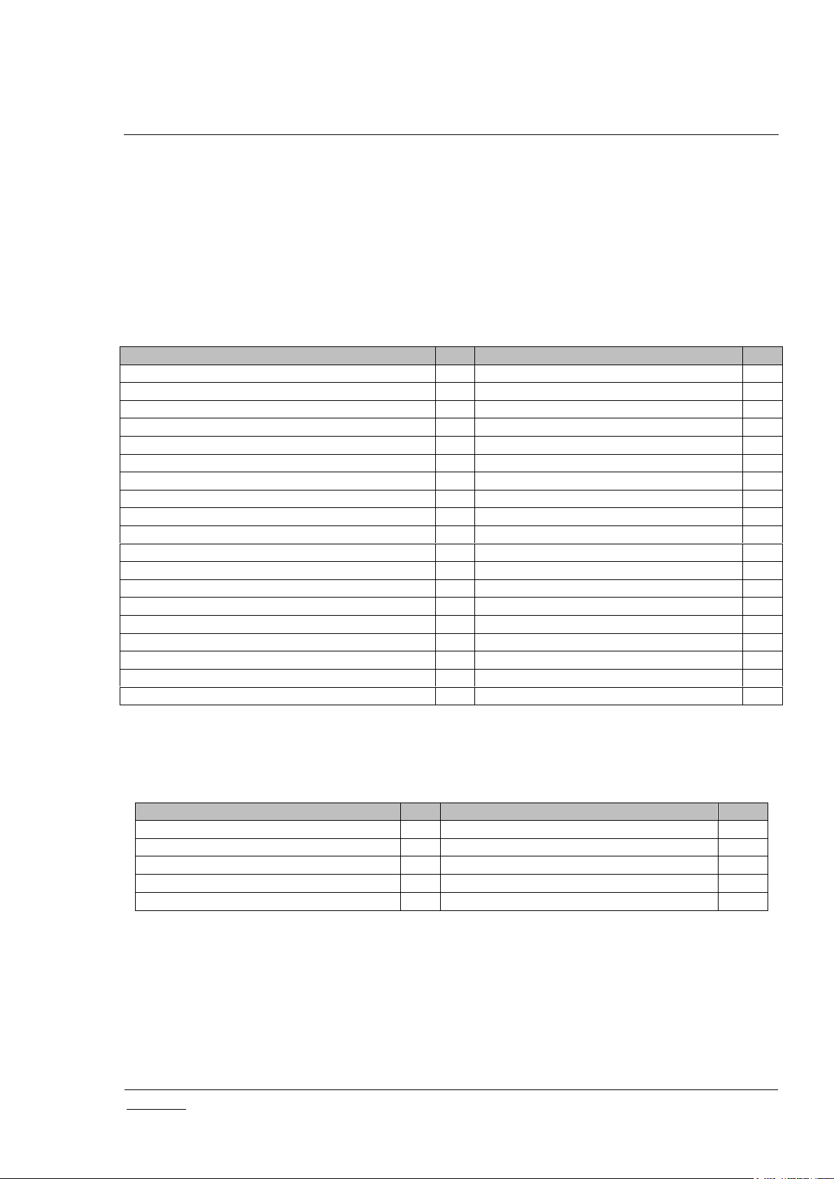
REVISION RECORD
Doc. Ver.
Date
By
Pages
affected
Brief description of changes
1
20170901
SNA
ALL
SDK v1.10: Cloned for new UI and SmartStart
2
20171108
SNA
8,32,31,33
Added native UI download & display information; updated About pages
3
20171212
SNA
3,26,30,
32,42,47,50
SDK v1.11: CC updates, iPhone native scanning for Add Node & Smart Start,
Eng UI – SmartStart, Basic, Thermostat State, Configuration
4
20180116
SNA
8,32,
3,
31,33,44,46,
26
Added Android & iPad Native Apps support; removed WebRenderer,
Corrected Controlled CCs for Config CC to v2, Corrected 2.8x NIF for Security CC,
Updated Tab UI About; Eng UI About, Binary Switch & Doorlock Pages
Added note on unpredictable effects of Abort during Add Node
,
Page 3

INS14072-5 Z-Ware Web User Guide for SDK v1.11 2018-03-08
silabs.com | Building a more connected world.
Page iii of vi
Table of Contents
1 INTRODUCTION ................................................................................................................................... 1
1.1 Purpose .............................................................................................................................................. 1
1.2 Audience and prerequisites ................................................................................................................ 1
2 OVERVIEW ........................................................................................................................................... 2
2.1 Z-Ware Library.................................................................................................................................... 2
2.1.1 Role .......................................................................................................................................... 2
2.1.2 Network Operations ................................................................................................................. 2
2.1.3 Device Control .......................................................................................................................... 3
2.1.4 Command Class Support ......................................................................................................... 3
2.1.5 Network Initialization ................................................................................................................ 5
2.1.6 Node Update ............................................................................................................................ 6
2.1.7 Network Update ....................................................................................................................... 7
2.1.8 Background Polling .................................................................................................................. 7
2.1.9 Post-Set Polling ........................................................................................................................ 7
2.1.10 Command Class Configuration ................................................................................................ 7
2.2 Scenes ................................................................................................................................................ 8
2.3 Bundled Z-Ware Apps ........................................................................................................................ 8
3 ACCESS ................................................................................................................................................ 9
3.1 Login ................................................................................................................................................... 9
3.1.1 CE ............................................................................................................................................ 9
3.1.2 Portal ........................................................................................................................................ 9
3.1.2.1 Registration ...................................................................................................................... 9
3.1.2.2 Reset password ..............................................................................................................10
4 TABLET/PC AND PHONE UI .............................................................................................................12
4.1 Scenes ..............................................................................................................................................12
4.1.1 Scene Summary .....................................................................................................................14
4.1.2 Scene Action ..........................................................................................................................15
4.1.3 Scene Schedule .....................................................................................................................16
4.1.4 Scene Trigger .........................................................................................................................16
4.1.5 Security Scene Summary .......................................................................................................17
4.1.6 Security Scene Arming ...........................................................................................................17
4.1.7 Security Scene Disarming ......................................................................................................18
4.1.8 Security Scene Alarm .............................................................................................................18
4.1.9 Security Scene Alarm Popup .................................................................................................19
4.2 Devices .............................................................................................................................................20
4.2.1 Binary Sensor Device .............................................................................................................21
4.2.2 Alarm/Notification Device .......................................................................................................21
4.2.3 Meter Device ..........................................................................................................................22
4.2.4 Multilevel Sensor Device ........................................................................................................22
4.2.5 Binary Switch Device .............................................................................................................22
4.2.6 Dimmer Device .......................................................................................................................22
4.2.7 Shades Device .......................................................................................................................23
4.2.8 Door Lock Device ...................................................................................................................23
4.2.9 Central Scene Controller ........................................................................................................24
4.2.10 Thermostat Device .................................................................................................................25
4.2.11 Barrier Operator Device .........................................................................................................25
4.3 More .................................................................................................................................................25
4.3.1 Maintenance ...........................................................................................................................26
4.3.1.1 Add/Remove Devices (Optionally On Behalf) ................................................................26
4.3.1.2 Reset Network ................................................................................................................28
4.3.1.3 Update Network ..............................................................................................................28
Page 4

INS14072-5 Z-Ware Web User Guide for SDK v1.11 2018-03-08
silabs.com | Building a more connected world.
Page iv of vi
4.3.1.4 Set Learn Mode ..............................................................................................................28
4.3.1.5 Broadcast NIF.................................................................................................................29
4.3.1.6 Remove/Replace Failed Devices (Optionally On Behalf) ..............................................29
4.3.1.7 Update Device ................................................................................................................29
4.3.1.8 Send NIF ........................................................................................................................30
4.3.2 SmartStart ..............................................................................................................................30
4.3.2.1 Add Device .....................................................................................................................30
4.3.2.2 Edit Device .....................................................................................................................31
4.3.2.3 Z-Wave Reset Requirement Detection ..........................................................................31
4.3.3 About ......................................................................................................................................31
4.4 Native UI ...........................................................................................................................................32
5 ENGINEERING UI ...............................................................................................................................33
5.1 Home ................................................................................................................................................33
5.2 About ................................................................................................................................................33
5.3 Network Manager .............................................................................................................................34
5.3.1 Security 2 Operations .............................................................................................................35
5.3.2 Network Health Check ...........................................................................................................37
5.4 SmartStart ........................................................................................................................................37
5.5 Controller ..........................................................................................................................................40
5.6 Interfaces ..........................................................................................................................................42
5.6.1 Basic .......................................................................................................................................42
5.6.2 Binary Sensor .........................................................................................................................42
5.6.3 Multi-Level Sensor .................................................................................................................43
5.6.4 Alarm/Notification ...................................................................................................................43
5.6.5 Meter ......................................................................................................................................44
5.6.6 Battery ....................................................................................................................................44
5.6.7 Binary Switch .........................................................................................................................44
5.6.8 Multi-level Switch ...................................................................................................................44
5.6.9 Color Switch Interface ............................................................................................................45
5.6.10 Central Scene Controller ........................................................................................................45
5.6.11 Door Lock ...............................................................................................................................46
5.6.12 User Code ..............................................................................................................................46
5.6.13 Barrier Operator Interface ......................................................................................................47
5.6.14 Thermostat related interfaces ................................................................................................47
5.6.14.1 Thermostat Fan ..............................................................................................................47
5.6.14.2 Thermostat Mode And Operating State .........................................................................47
5.6.14.3 Thermostat SetPoint .......................................................................................................48
5.6.15 Naming/Location ....................................................................................................................48
5.6.16 Association .............................................................................................................................49
5.6.17 Configuration ..........................................................................................................................50
5.6.18 Wake up .................................................................................................................................51
5.6.19 Command Queuing ................................................................................................................51
5.6.20 Firmware Update ....................................................................................................................52
5.6.21 Z/IP Gateway .........................................................................................................................52
5.7 Scenes ..............................................................................................................................................55
5.8 Security Scenes................................................................................................................................57
REFERENCES ...........................................................................................................................................60
Table 1: ZIPGW Versions vs Features as used by Z-Ware ........................................................................ 2
Table 2: UI Controlled Z-Wave CCs ............................................................................................................ 3
Table of Tables
Page 5

INS14072-5 Z-Ware Web User Guide for SDK v1.11 2018-03-08
silabs.com | Building a more connected world.
Page v of vi
Table 3: Controlled Z-Wave CCs inherited through Library ........................................................................ 3
Table 4: ZIPGW SDK 2.8x Supported Z-Wave CCs ................................................................................... 4
Table 5: ZIPGW SDK 2.1x Supported Z-Wave CCs ................................................................................... 4
Table 6: ZIPGW SDK 2.0x Supported Z-Wave CCs ................................................................................... 4
Table 7: Node Update get/set CCs .............................................................................................................. 6
Table 8: Node Update endpoint get/set CCs ............................................................................................... 6
Table 9: Bundled Z-Ware Apps and URIs ................................................................................................... 8
Table 10: Z-Wave Network Buttons mapping ............................................................................................ 35
Table of Figures
Figure 1: Z-Ware CE running within a home on RPi3 ................................................................................. 1
Figure 2: Z-Ware Portal in the Cloud connected to multiple homes ............................................................ 1
Figure 3: Login page .................................................................................................................................... 9
Figure 4: Portal Registration Page ............................................................................................................ 10
Figure 5: Portal Reset Password Page ..................................................................................................... 11
Figure 6: Tab UI - Scenes ......................................................................................................................... 12
Figure 7: Tab UI - Scenes Edit .................................................................................................................. 13
Figure 8: Tab UI - Scenes Toggle ............................................................................................................. 14
Figure 9: Tab UI: Scene View Summary ................................................................................................... 15
Figure 10: Tab UI - Scene View Action ..................................................................................................... 16
Figure 11: Tab UI - Scene Schedule ......................................................................................................... 16
Figure 12: Tab UI - Scene Trigger ............................................................................................................. 17
Figure 13: Tab UI - Security Scene Summary ........................................................................................... 17
Figure 14: Tab UI - Security Scene Arm.................................................................................................... 18
Figure 15: Tab UI - Security Scene Disarm ............................................................................................... 18
Figure 16: Tab UI - Security Scene Alarm ................................................................................................. 19
Figure 17: Tab UI - Security Scene Alarm Popup ..................................................................................... 19
Figure 18: Tab UI - Devices ....................................................................................................................... 20
Figure 19: Tab UI - Show Details .............................................................................................................. 21
Figure 20: Tab UI - Binary Sensor ............................................................................................................. 21
Figure 21: Tab UI – Alarm/Notification Interface Type/Event .................................................................... 22
Figure 22: Tab UI - Meter Interface ........................................................................................................... 22
Figure 23: Tab UI - Multilevel Sensor Interface ......................................................................................... 22
Figure 24: Tab UI - Binary Switch Device.................................................................................................. 22
Figure 25: Tab UI - Dimmer (Multilevel Switch Non-Motor) Device .......................................................... 23
Figure 26: Tab UI - Shades (Multilevel Switch Motor) Device ................................................................... 23
Figure 27: Tab UI - Door Lock Device ....................................................................................................... 24
Figure 28: Tab UI - Central Scene Controller Device ................................................................................ 24
Figure 29: Tab UI - Thermostat Device ..................................................................................................... 25
Figure 30: Tab UI - Barrier Operator Device ............................................................................................. 25
Figure 31: Tab UI – Maintenance (Network) ............................................................................................. 26
Figure 32: Tab UI - Add New Device: Initiate ............................................................................................ 26
Figure 33: Tab UI - Add New Device: Grant Keys ..................................................................................... 27
Figure 34: Tab UI - Add New Device: DSK ............................................................................................... 27
Figure 35: Tab UI - Add New Device: CSA DSK info ................................................................................ 27
Figure 36: Tab UI – Set Learn Mode ......................................................................................................... 28
Figure 37: Tab UI - Replace Failed Device ............................................................................................... 29
Figure 38: Tab UI – SmartStart ................................................................................................................. 30
Figure 39: Tab UI - SmartStart Add Device ............................................................................................... 30
Figure 40: Tab UI - SmartStart Edit Device ............................................................................................... 31
Figure 41: Tab UI - SmartStart Z-Wave Reset Requirement Detection .................................................... 31
Figure 42: Tab UI - About .......................................................................................................................... 31
Figure 43: Eng UI - Home Page ................................................................................................................ 33
Page 6

INS14072-5 Z-Ware Web User Guide for SDK v1.11 2018-03-08
silabs.com | Building a more connected world.
Page vi of vi
Figure 44: Eng UI - About Page ................................................................................................................ 33
Figure 45: Eng UI - Network Manager Page ............................................................................................. 34
Figure 46: Eng UI - Network operation progress UI .................................................................................. 35
Figure 47: Eng UI - S2 Accepting Security Keys ....................................................................................... 36
Figure 48: Eng UI - S2 Entering DSK ........................................................................................................ 36
Figure 49: Eng UI - S2 CSA ...................................................................................................................... 37
Figure 50: Eng UI – Network Health Check .............................................................................................. 37
Figure 51: Eng UI - SmartStart List ........................................................................................................... 38
Figure 52: Eng UI - SmartStart Add/Edit Device ....................................................................................... 39
Figure 53: Eng UI – SmartStart Z-Wave Reset Required Detection ......................................................... 40
Figure 54: Eng UI - Node Controller Page ................................................................................................ 41
Figure 55: Eng UI - Node Version/Info UI .................................................................................................. 41
Figure 56: Eng UI - Endpoint Z-Wave+ Info UI.......................................................................................... 42
Figure 57: Eng UI - Basic Interface UI ....................................................................................................... 42
Figure 58: Eng UI - Binary Sensor Interface UI ......................................................................................... 42
Figure 59: Eng UI - Multilevel Sensor Interface UI .................................................................................... 43
Figure 60: Eng UI – Alarm/Notification Interface UI .................................................................................. 43
Figure 61: Eng UI - Meter Interface UI ...................................................................................................... 44
Figure 62: Eng UI - Battery Interface UI .................................................................................................... 44
Figure 63: Eng UI - Binary Switch Interface UI .......................................................................................... 44
Figure 64: Eng UI - Multilevel Switch Interface UI ..................................................................................... 45
Figure 65: Eng UI - Color Switch Interface ................................................................................................ 45
Figure 66:: Eng UI - Central Scene Controller Interface UI ....................................................................... 45
Figure 67: Eng UI - Door Lock Interface UI ............................................................................................... 46
Figure 68: Eng UI - User Code Interface UI .............................................................................................. 46
Figure 69: Eng UI - Barrier Operator Interface UI ..................................................................................... 47
Figure 70: Eng UI - Thermostat Fan Interface UI ...................................................................................... 47
Figure 71: Eng UI - Thermostat Mode And State Interface UI .................................................................. 48
Figure 72: Eng UI - Thermostat Setpoint Interface UI ............................................................................... 48
Figure 73: Eng UI - Name/Location Interface UI ....................................................................................... 49
Figure 74: Eng UI - Group Interface UI...................................................................................................... 49
Figure 75: Eng UI - Group with AGI Interface UI ....................................................................................... 50
Figure 76: Eng UI - Configuration Interface UI .......................................................................................... 51
Figure 77: Eng UI - Wakeup Interface UI .................................................................................................. 51
Figure 78: Command Queuing Interface UI .............................................................................................. 52
Figure 79: Eng UI - Firmware Update Interface UI .................................................................................... 52
Figure 80: Eng UI – ZIPGW Interface Portal Mode UI .............................................................................. 53
Figure 81: Eng UI - ZIPGW Interface Standalone Mode UI ...................................................................... 54
Figure 82: Eng UI - Scenes Page .............................................................................................................. 55
Figure 83: Eng UI - Scene Edit UI ............................................................................................................. 56
Figure 84: Eng UI - Security Scenes Page ................................................................................................ 57
Figure 85: Eng UI - Security Scene Edit UI ............................................................................................... 58
Figure 86: Eng UI - Security Scene Notification Edit UI ............................................................................ 59
Page 7
INS14072-5 Z-Ware Web User Guide for SDK v1.11 2018-03-08
silabs.com | Building a more connected world.
Page 1 of 61
Z-Wave
Device
iPad/iPhone
RPi3
Z-Ware Web Server
Z-Ware Library
ZIPGW
Z-Ware Native Apps
Z-Wave
Device
PC Web Browser
Z-Ware Web Apps
RPi3
Z-Wave
Device
iPad/iPhone
Cloud Linux VM
Z-Ware Web Server
Z-Ware Library
ZIPGW
Z-Ware Native Apps
Z-Wave
Device
PC Web Browser
Internet
Z-Ware Apps
1 INTRODUCTION
1.1 Purpose
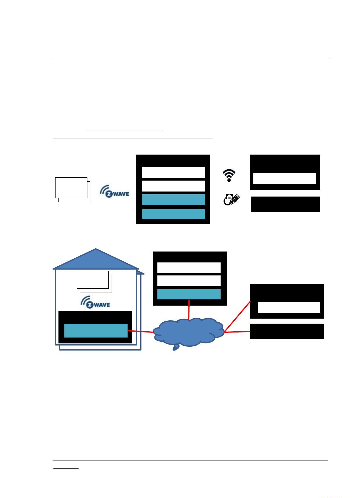
Z-Ware is a Z-Wave controller middleware running over a Z-Wave over IP (Z/IP) Gateway (ZIPGW) as a
Web Gateway. Z-Ware Apps (Z-Apps) are web pages built into the Z-Ware Web Server providing UI for
phones and tablets/PCs. Z-Ware can be run in either Consumer Electronic (CE) on BBB (BeagleBone
Black – see https://beagleboard.org/black) or RPi3 (Raspberry Pi 3 – see
https://www.raspberrypi.org/products/raspberry-pi-3-model-b/) platforms in the home or Portal mode on a
Linux Virtual Machine (VM) in the Cloud as shown below.
Android Phone/Tab
Figure 1: Z-Ware CE running within a home on RPi3
Android Phone/Tab
Figure 2: Z-Ware Portal in the Cloud connected to multiple homes
This document covers the usage of Z-Ware Web Server and Apps for both CE and Portal and will
explicitly state if instructions are for any particular mode.
The diagrams shown in this guide are for Windows with Internet Explorer 8 unless otherwise specified.
Your experience may vary slightly depending on your platform configuration.
1.2 Audience and prerequisites
Z-Wave Web users
Page 8
INS14072-5 Z-Ware Web User Guide for SDK v1.11 2018-03-08
silabs.com | Building a more connected world.
Page 2 of 61
ZIPGW SDK
Mailbox
Security
N/W Health
Smart Start
2.0x
Unused; Uses Wakeup CC directly
S0
N.A.
N.A.
2.1x
Used
S0, S2
N.A.
N.A.
2.8x
Used
S0, S2
Used
Used
2 OVERVIEW
2.1 Z-Ware Library
The Z-Ware Library, which abstracts the ZIPGW, provides Z-Wave Command Class (CC) level APIs,
discovery of device capability and state, is statically linked into the Z-Ware web server. It provides the
following features.
2.1.1 Role
Z-Ware is a Z-Wave Plus Security Enabled device in the Static PC Controller class, that is mainly used in
the role of a Static Update Controller (SUC) Identity Server (SIS), and the Z-Wave Plus role of a Central
Static Controller.
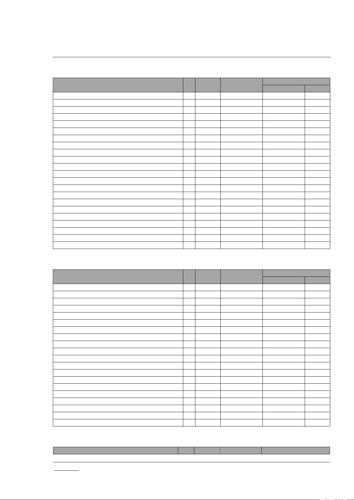
2.1.2 Network Operations
As a Z/IP client, it works in conjunction with a ZIPGW. Z-Ware sets itself as the (first) unsolicited IP
address of the ZIPGW that it is connected with. Z-Ware works with the different versions of ZIPGWs
using the following features:
Table 1: ZIPGW Versions vs Features as used by Z-Ware
Similarly ZIPGW works with different versions of Z-Wave Protocols and certain features may not be
available on older versions. SmartStart is only available with Z-Wave Protocol SDK 6.8x onwards.
Z-Ware supports Inclusion, Exclusion, Reset (Set Default), Replace/Remove Failed Node, and Send
Node NIF (Node Information Frame). If it is assigned a primary controller role, it will always upgrade
itself to an SIS unless there is an SUC already present. Hence it cannot initiate controller shift as a
primary.
Z-Ware supports Set Learn mode but this can only be performed when Z-Ware is not already in a
network and will typically make Z-Ware an Inclusion or Secondary Controller, in which case, some of its
facilities will not be available. Controller replication (Copy) is achieved through Inclusion and Set Learn
Mode.
Additionally it also supports Node and Network Update. Z-Ware discovers a Z-Wave node’s capabilities
during inclusion through a series of comprehensive queries. This process may take some time,
especially for a secure Frequently Listening Routing Slave (FLIRs) device. This operation may be
aborted at any time. Node Update re-queries the information that was obtained during inclusion. This
allows discovering any changes that were not made through this Z-Ware. Network Update requests
topology from an SUC if available, and then performs neighbor update if available or node update to
every node it is aware of.
Z-Ware supports SmartStart which uses a configurable provisioning list of devices to allow Z-Wave
network wide inclusion without having to manually configure a new node into Z-Wave learn mode. The
availability of this feature is dependent on the underlying ZIPGW and protocol.
Page 9
INS14072-5 Z-Ware Web User Guide for SDK v1.11 2018-03-08
silabs.com | Building a more connected world.
Page 3 of 61
CC
Ver
CC
Ver
ASSOCIATION
2
NOTIFICATION/ALARM
8
ASSOCIATION_GRP_INFO
3
SECURITY
1
BARRIER_OPERATOR
1
SECURITY 2*
1
BASIC
2
SENSOR_BINARY
2
BATTERY
1
SENSOR_MULTILEVEL
11
CENTRAL_SCENE
3
SWITCH_BINARY
2
CONFIGURATION
2
SWITCH_COLOR
3
DOOR_LOCK
3
SWITCH_MULTILEVEL
4
FIRMWARE_UPDATE_MD
5
THERMOSTAT_FAN_MODE
4
MANUFACTURER_SPECIFIC
2
THERMOSTAT_FAN_STATE
2
METER
3
THERMOSTAT_MODE
3
MULTI_CHANNEL
4
THERMOSTAT_OPERATING_STATE
2
MULTI_CHANNEL_ASSOCIATION
3
THERMOSTAT_SETPOINT
3
NW_MGMT_BASIC
2
USER_CODE
1
NW_MGMT_INCLUSION
3
VERSION
2
NW_MGMT_INSTALLATION_MAINTENANCE*
1
WAKE_UP
2
NW_MGMT_PROXY
2
ZIP_GATEWAY
1
NODE_NAMING
1
ZIP_PORTAL
1
NODE_PROVISIONING*
1
ZWAVEPLUS_INFO
2
CC
Ver
CC
Ver
ALARM SENSOR
1
NO_OPERATION
1
APPLICATION_STATUS
1
POWERLEVEL
1
CRC_16_ENCAP
1
SUPERVISION
1
DEVICE_RESET_LOCALLY
1
ZIP
3
MULTI_CMD
1
ZIP_ND
1
2.1.3 Device Control
Z-Ware can be operated in any Z-Wave network with other Z-Wave certified devices from other
manufacturers. All non-battery operated nodes within the network will act as repeaters regardless of
vendor to increase reliability of the network.
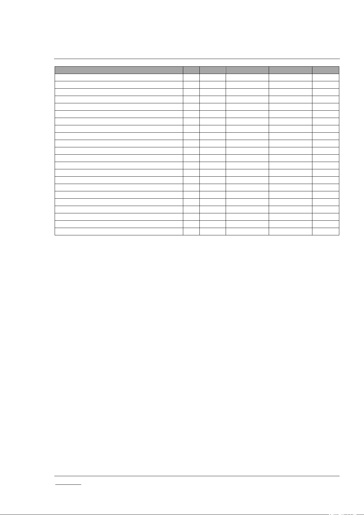
Z-Ware is able to control/monitor Z-Wave-certified device of different categories from various vendors
through their CCs. CCs that are automatically handled are not exposed to the user. Z-Ware controls the
following CCs and versions:
Table 2: UI Controlled Z-Wave CCs
* Security 2, Network Management Installation Maintenance and Node Provisioning CCs only controlled
if the underlying ZIPGW supports them.
Table 3: Controlled Z-Wave CCs inherited through Library
2.1.4 Command Class Support
Z-Ware does nothing on receiving Basic CC Set or Get, unless Basic Set from any particular
node/endpoint is used as a Scene trigger. Z-Ware supports only 1 Association group supporting 1 node
for Lifeline. This node will receive the Device Reset Locally command.
For easier reference during certification the associated ZIPGW supported CCs are tabularized below.
Page 10
INS14072-5 Z-Ware Web User Guide for SDK v1.11 2018-03-08
silabs.com | Building a more connected world.
Page 4 of 61
CC
Ver
Not
added
Non-secure
added
Securely added
Non-Secure
Secure
APPLICATION_CAPABILITY
1 X X X
APPLICATION_STATUS
1 X X X
ASSOCIATION *
2 X X X
ASSOCIATION_GRP_INFO *
3 X X X
CRC_16_ENCAP
1 X X X
DEVICE_RESET_LOCALLY *
1 X X X
FIRMWARE_UPDATE_MD
5 X
INCLUSION_CONTROLLER **
1 X X X
MANUFACTURER_SPECIFIC
2 X X X
MULTI_CMD *
1 X X X
NODE PROVISIONING ***
1 X
NW_MGMT_BASIC
2 X
NW_MGMT_INCLUSION **
3 X
NW_MGMT_INSTALLATION_MAINTENANCE
1 X
NW_MGMT_PROXY
2 X
POWERLEVEL
1 X X X
SECURITY
1 X X
SECURITY_2
1 X X X
SUPERVISION
1 X X X
TRANSPORT_SERVICE
2 X X X
VERSION
2 X X X
ZWAVEPLUS_INFO
2 X X X
CC
Ver
Not
added
Non-secure
added
Securely added
Non-Secure
Secure
APPLICATION_STATUS
1 X X X
ASSOCIATION *
2 X X X
ASSOCIATION_GRP_INFO *
3 X X X
CRC_16_ENCAP
1 X X X
DEVICE_RESET_LOCALLY *
1 X X X
FIRMWARE_UPDATE_MD
5 X
INCLUSION_CONTROLLER **
1 X X X
MANUFACTURER_SPECIFIC
2 X X
MULTI_CMD *
1 X X X
NW_MGMT_BASIC
2 X
NW_MGMT_INCLUSION **
2 X
NW_MGMT_INSTALLATION_MAINTENANCE
1 X
NW_MGMT_PROXY
2 X
POWERLEVEL
1 X X
SECURITY
1 X X
SECURITY_2
1 X X X
SUPERVISION
1 X X X
TRANSPORT_SERVICE
2 X X X
VERSION
2 X X
ZWAVEPLUS_INFO
2 X X X
CC
Ver
Not
Non Secure
Securely Added
Table 4: ZIPGW SDK 2.8x Supported Z-Wave CCs
Table 5: ZIPGW SDK 2.1x Supported Z-Wave CCs
Table 6: ZIPGW SDK 2.0x Supported Z-Wave CCs
Page 11
INS14072-5 Z-Ware Web User Guide for SDK v1.11 2018-03-08
silabs.com | Building a more connected world.
Page 5 of 61
Added
Added
Non Secure
Secure
SECURITY
1 X X X
TRANSPORT SERVICE
2 X X X
CRC16
1 X X X
MULTI CMD *
1 X X X
NW MGMT BASIC
2 X
NW MGMT INCLUSION **
2 X
NW MGMT PROXY
2 X
NW MGMT INSTALLATION MAINTENANCE
1 X
DEVICE RESET LOCALLY *
1 X X X
ZIP 3 X ZIP PORTAL
1 X
ZIP GATEWAY
1 X
ZIP NAMING
1 X
FIRMWARE UPDATE MD
5 X
MAILBOX
1 X
POWER LEVEL
1 X
APPLICATION STATUS
1 X X X
ZWAVEPLUS INFO
2 X X X
MANUFACTURER SPECIFIC
2 X
VERSION
2 X
ASSOCIATION *
2 X X X
ASSOCIATION GRP INFO *
3 X X X
* ASSOCIATION, ASSOCIATION_GRP_INFO, MULTI_CMD and DEVICE_RESET_LOCALLY CCs are
added by Z-Ware to the ZIPGW NIF
** INCLUSION_CONTROLLER and NW_MGMT_INCLUSION CCs are only present if the ZIPGW is an
inclusion controller.
*** NODE_PROVISIONING is only available in an S2 enabled network.
2.1.5 Network Initialization
The following steps are carried out during network initialization:
1. Get ZIPGW’s Z-Wave Home ID, Node ID and Home Area Network (HAN) IP address.
2. Get ZIPGW attached controller’s cached node information.
3. Get CC versions present in the ZIPGW cached node information to create corresponding Z-Ware
interfaces.
4. Get ZIPGW’s hardware and firmware versions if VERSION CC is v2 or higher.
5. Get ZIPGW’s manufacturer, product type and product id if MANUFACTURER_SPECIFIC CC
presents.
6. Get node list of the HAN.
7. Turn on mailbox for ZIPGW SDK v2.1x and above. This will enable multi-client support and receive
wake up notification from device through mailbox ACK message.
8. Get ZIPGW dynamic DSK key for adding new node.
9. Set supported CCs in the ZIPGW attached controller’s NIF
10. For Portal version, set unsolicited destination address. For CE version, get unsolicited destination
address and if its IPv6 address is all zeroes, set it to the Z/IP client IPv6 address.
11. Resolve all the nodes in node list into corresponding HAN IPv6 addresses.
12. Perform Node Update (see 2.1.6 Node Update) through HAN network for nodes that are not loaded
with detailed node information from persistent storage.
Page 12

INS14072-5 Z-Ware Web User Guide for SDK v1.11 2018-03-08
silabs.com | Building a more connected world.
Page 6 of 61
CC
CC
MANUFACTURER_SPECIFIC
VERSION
WAKE_UP
CC
CC
ASSOCIATION
SENSOR_BINARY
ASSOCIATION_GRP_INFO
SENSOR_MULTILEVEL
BARRIER_OPERATOR
SIMPLE_AV_CONTROL
2.1.6 Node Update
The following steps are carried out to acquire detailed node information based on the CCs present at
node and endpoint levels:
1. Get cached node information of the node of interest from the ZIPGW.
2. Assign the ZIPGW attached controller’s Z-Wave Return Route to the node.
3. Get CC versions of each CC listed in the node information.
4. Get library, protocol and application versions.
5. Get node’s hardware and firmware versions if Version CC is v2 or higher.
6. Get MANUFACTURER_SPECIFIC CC Manufacturer ID, Product Type and Product ID. Based on
these, get device category from the device setting database. Get Device Serial Number if supported.
7. If the node has just been added into the network, set the WAKEUP CC notification receiving Node ID
to SIS with/without changing the wakeup interval. The wakeup interval will be changed if global
setting for wakeup interval is non-zero in device database.
8. For each endpoint in the node :a) Get security supported CCs at the endpoint if the node is included securely
b) Get version of CCs at the endpoint
c) If the node has just been added into the network, set device specific configuration parameters
based on Device Database
d) Get ASSOCIATION CC’s maximum supported group. If the node has just been added into the
network, and group 1 is “Lifeline”, set SIS node id into group 1
e) Get Central Scene CC number of supported scenes. . If the node has just been added into the
network, and Central Scene CC version is 3 and greater, then set it to slow refresh.
f) Get Z-Wave Plus Information
g) Get Multilevel Sensor CC supported types, units and current value
h) Get ASSOCIATION GROUP INFORMATION CC details
i) Get Thermostat Fan Operating Mode CC supported modes, Thermostat Mode CC supported and
current mode, Thermostat Setpoint CC supported and current type and also temperature range,
Thermostat Operating State CC current state
j) Get Multilevel Switch CC supported types and current value
k) Get Simple AV CC supported controls
l) Get Alarm/Notification CC supported types and events
m) Get Protection CC supported states
n) Get User Code CC maximum supported codes
o) Get Meter CC capabilities and descriptor
p) Get Binary Sensor CC supported types and current value
q) Get Door Lock CC current state
r) Get Alarm Sensor CC supported types and current value
s) Get Barrier Operator CC current state
t) Get Color Switch CC supported components and current values
u) Get Binary Switch CC current state
v) Get Battery CC current level
w) Get Node Naming CC current name and location
Table 7: Node Update Get/Set CCs
Table 8: Node Update Endpoint Get/Set CCs
Page 13

INS14072-5 Z-Ware Web User Guide for SDK v1.11 2018-03-08
silabs.com | Building a more connected world.
Page 7 of 61
BATTERY
SWITCH_BINARY
CENTRAL_SCENE
SWITCH_COLOR
CLOCK
SWITCH_MULTILEVEL
CONFIGURATION
THERMOSTAT_FAN_MODE
DOOR_LOCK
THERMOSTAT_FAN_STATE
METER
THERMOSTAT_MODE
METER_TBL_MONITOR
THERMOSTAT_OPERATING_STATE
MULTI_CHANNEL_ASSOCIATION
THERMOSTAT_SETPOINT
NODE_NAMING
USER_CODE
NOTIFICATION/ALARM
VERSION
PROTECTION
2.1.7 Network Update
The following steps are carried out to update the network:
1. Repeat steps 1 to 4 of Section 2.1.5 Network Initialization.
2. Request network update by using the command
COMMAND_CLASS_NETWORK_MANAGEMENT_BASIC -> NETWORK_UPDATE_REQUEST
3. Get node list of the HAN.
4. Resolve all the nodes in node list into corresponding HAN IPv6 addresses.
5. Request node neighbor update for each of the node in the node list. Repeat for up to 3 iterations
if the request node neighbor update failed for some nodes that may be out-of-range.
6. Perform Node Update for each node in network (See 2.1.6 Node Update).
2.1.8 Background Polling
Z-Ware Library performs automatic background polling to cache device supported interface details (e.g.
supported sensor types and units) and device values (e.g. sensor readings for each supported type). For
always-on devices, polling is carried out for all relevant interfaces in a device followed by an interval of
10 seconds before the next device is polled. For FLIRS (Frequently Listening Routing Slave) devices,
polling is carried out only every 12 hours per device so as not to run the device’s batteries out. For
sleeping devices, polling is carried out whenever they wake up. As sleeping devices will go to sleep
mode when they don’t receive any Z-Wave messages, this type of polling has higher priority than the
other two types of polling. The polling sequence of CCs are the same as those listed for each endpoint
in Section 2.1.6 Node Update.
2.1.9 Post-Set Polling
Some devices take time to reach their target settings especially mechanical devices. Z-Ware Library
performs post-set polling for door lock, multi-level switch motor and barrier operator interfaces. For door
locks, the polling intervals are 1, 2, 3 seconds; whereas for multi-level switch, the intervals are 1, 2, 3, 4
seconds before timeout occurs. For Barrier Operator CC, the intervals are 1 to 7 seconds incrementally.
If the endpoint supports the Supervision CC, then polling is not performed and notification is expected
from the device on completion. This allows the client to be informed if/when the device has reached its
target state
2.1.10 Command Class Configuration
Some library clients may want to only implement control for selected CCs of those offered. However this
leads to Z-Wave certification form failures as the library performs background polling and information
caching for CCs not listed in the form. A CC configuration option file “cmd_class.cfg” list all CCs offered
allowing the client developer to comment out undesired CCs.
Page 14
INS14072-5 Z-Ware Web User Guide for SDK v1.11 2018-03-08
silabs.com | Building a more connected world.
Page 8 of 61
UI
Base URI or location
Tablet/PC Web
/ui/pc/index.html
Phone Web
/ui/phone/index.html
Engineering Web
/ui/eng/index.html
iOS Native
https://itunes.apple.com/app/z-wave/id1296166426
Android Native
https://play.google.com/store/apps/details?id=com.sigmadesigns.zwareapp
2.2 Scenes
A Z-Ware Scene is a set of actions that may be activated by triggers. An action is a Z-Wave SET
command, for e.g., to turn on a switch. A trigger may be a user request through a UI element, by
schedule or on an event. A schedule can be set to execute a Scene on any or every day of the week at
a preset time. A schedule remains active till it is disabled or deleted. An event refers to the receipt of a
Z-Wave report, typically a sensor report e.g. motion sensed. The state of a scene, i.e. whether it is
completely activated, can also be monitored.
A Z-Ware Security Scene is a special Scene that can be armed or disarmed by a key fob or a door lock
event or through the UI. It can only be triggered when it is armed. When triggered, it can send out alerts
using email and/or SMS. Arming, disarming and triggering can also be configured to activate normal
scenes.
Supported actions are Basic, Binary Switch, Multilevel Switch, Door Lock, Thermostat Setpoint CC SET
commands. Supported events are Binary Sensor, Multilevel Sensor, Alarm/Notification, Door Lock CC
REPORT commands as well as a Basic SET command received from trigger sources.
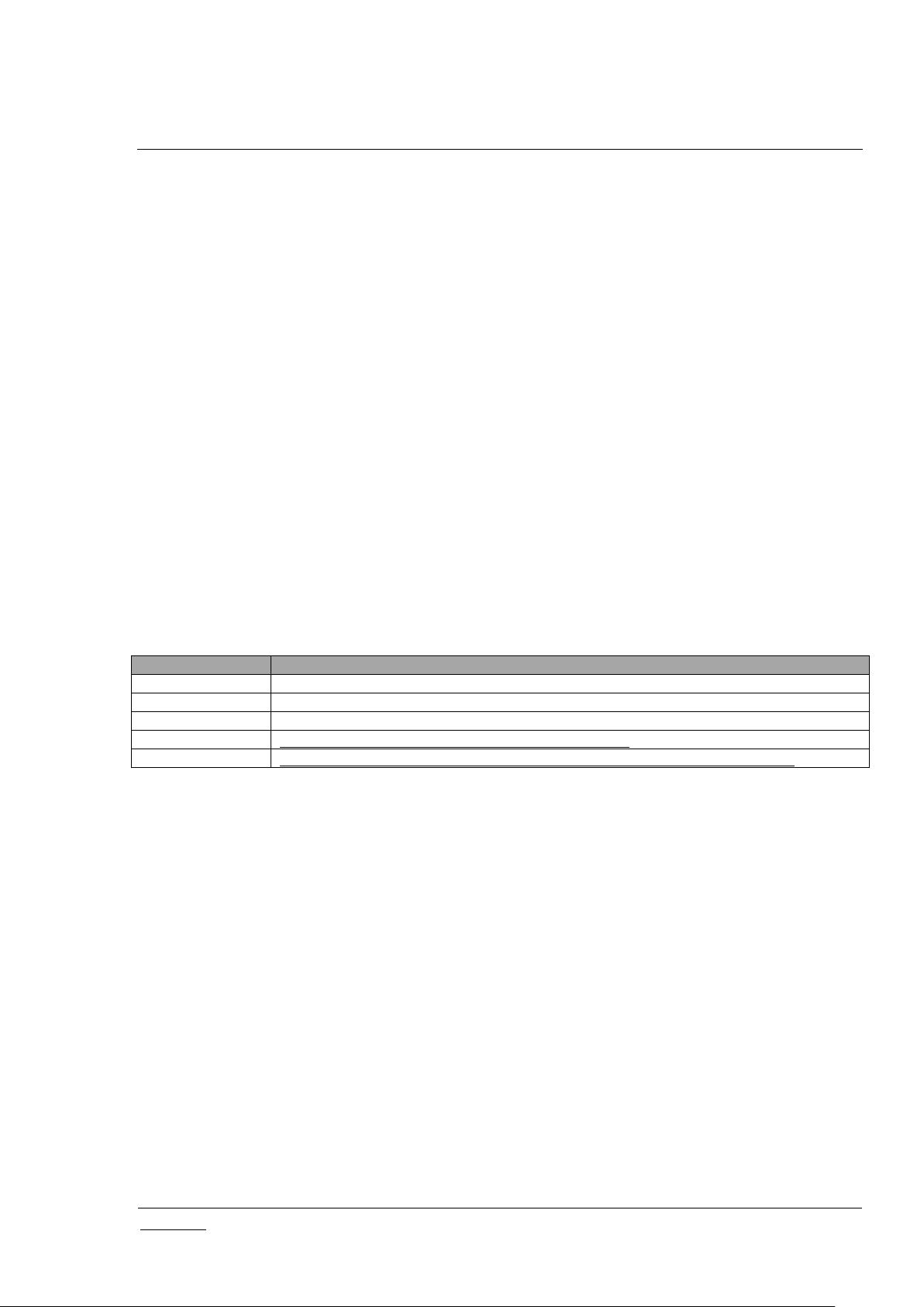
2.3 Bundled Z-Ware Apps
Consumer-friendly UIs targeted for Tablet/PC and Phone are included, as well as an Engineering version
meant to demonstrate the server’s capabilities.
Table 9: Bundled Z-Ware Apps and URIs
On web login, the Tablet or Phone UI is automatically selected by the server based on the User Agent of
the web browser used.
Differences in the UIs are as follows:
Engineering UI exposes advanced Z-Wave interfaces related to the Association and
Configuration CCs.
Network Health functionality is only available on the Engineering UI.
Scanning of QR code is only available in the Native UIs.
Users can build their own apps over the Z-Ware Web API – see [1].
Page 15
INS14072-5 Z-Ware Web User Guide for SDK v1.11 2018-03-08
silabs.com | Building a more connected world.
Page 9 of 61
3 ACCESS
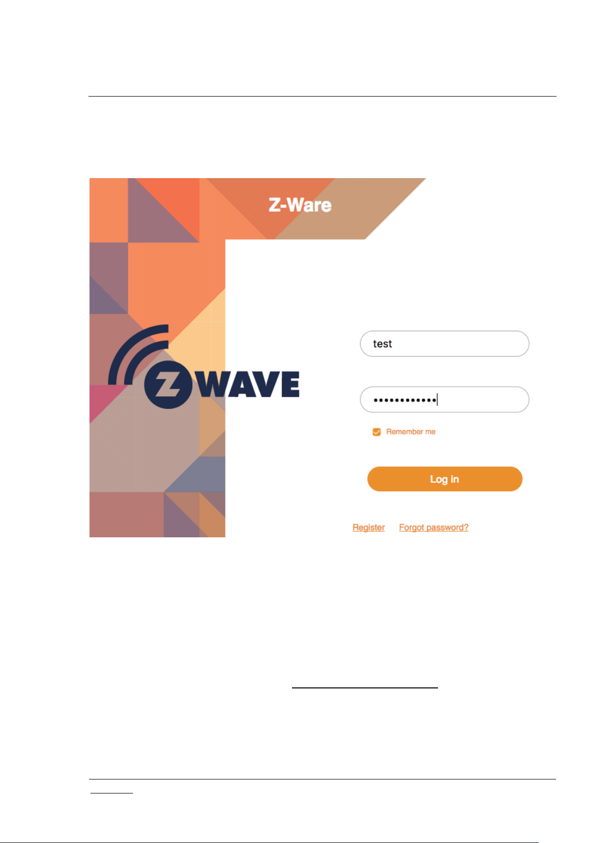
3.1 Login
3.1.1 CE
CE users access their accounts on the machine they have installed at https://<machine IP address>.
The default username and password are ‘sigma’ and ‘sigmadesigns’ respectively. The page will be titled
“CE” instead of “Portal” and the links at the bottom will not be there.
3.1.2 Portal
Z-Ware Portal users access their accounts at https://z-ware.sigmadesigns.com . They can login and
create their account or reset the account password through the links at the bottom.
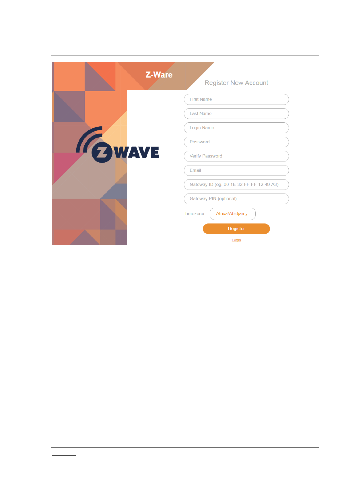
3.1.2.1 Registration
To create the Portal account, the user needs to fill in the registration details.
Figure 3: Login page
Page 16
INS14072-5 Z-Ware Web User Guide for SDK v1.11 2018-03-08
silabs.com | Building a more connected world.
Page 10 of 61
Figure 4: Portal Registration Page
First and last names are alphabets only and between 3 to 25 characters in length. Username is of the
same length but can be alphanumeric, in addition supporting both ‘_’ (underscore) and ‘.’ (period) special
characters. Password must be between 8 to 16 characters in length.
The Gateway ID is the ZIPGW platform Ethernet MAC address which can be obtained as specified in the
ZIPGW documentation. The Gateway PIN is optional and only relevant to the ZIPR which comes labeled
with the PIN, and the RAC (Remote Access Code) should be used as Gateway ID. The time zone
setting allows the server to convert time information in accordance to the locality of the ZIPGW.
On registration, an email is sent to the registered email address which contains an unregister link in case
the user entered the wrong details and wishes to reregister and a link to download certificates to the
ZIPGW platform as specified in the ZIPGW documentation.
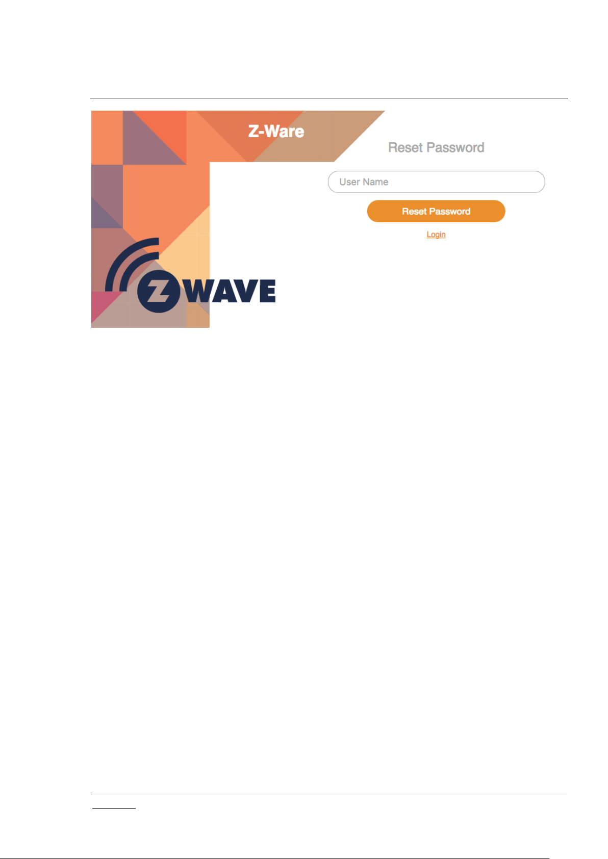
3.1.2.2 Reset password
The Portal account name needs to be specified to confirm resetting password. An email will be sent with
an unregister link, and the process will be the same as creating a new account.
Page 17
INS14072-5 Z-Ware Web User Guide for SDK v1.11 2018-03-08
silabs.com | Building a more connected world.
Page 11 of 61
Figure 5: Portal Reset Password Page
Page 18
INS14072-5 Z-Ware Web User Guide for SDK v1.11 2018-03-08
silabs.com | Building a more connected world.
Page 12 of 61
4 TABLET/PC AND PHONE UI
For the Tablet UI, the main menu appears on the left while for the Phone UI, it appears at the bottom.
There are not many other differences between the 2 UIs except layout. On the top right, for the Portal
version only, an icon shows the connection to the portal, blue when connected, grey otherwise. Users
can also log out on the top right of the Tablet UI.
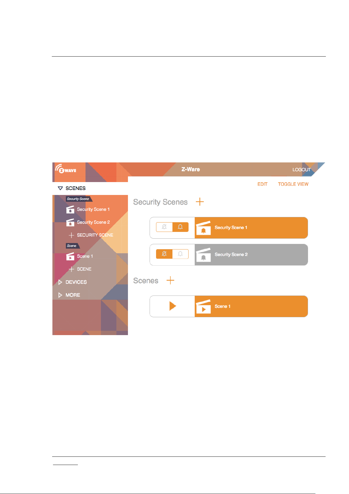
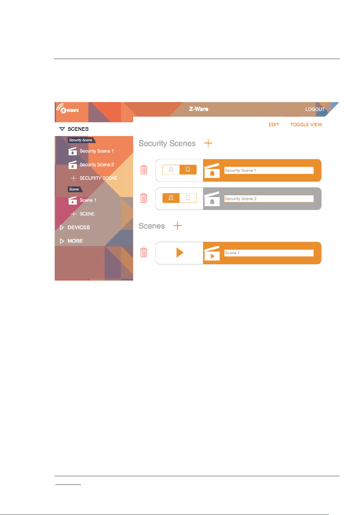
4.1 Scenes
The scenes page allows monitoring, manual activation and editing of a list of scenes. For more
information on Scenes, see Section 2.2 Scenes.
Normal scenes can be manually activated by the play icon. Security scenes can be armed or disarmed
with the bell or crossed bell icons respectively. Normal Scenes in active state and Security scenes in
armed state are shown in orange while others are in grey.
New scenes can be created with the ‘Scenes +’ and Security Scenes +’ links. Clicking on a scene will
enter the summary page.
have a clapper board icon and those that have configured schedule or event triggers have a clock
superimposed on the icon. Security Scenes have a bell superimposed on the icon. The turning wheel at
the top right indicates that the scenes are updating their status. Scene status is updated only when
Home or Scenes buttons are clicked, or when a scene is triggered. Clicking on a scene triggers it
manually, turning its tab blue and starting the status update. If for some reason, it is not activated, it
returns to its original color. As the same devices may be activated by multiple scenes, triggering 1 scene
Figure 6: Tab UI - Scenes
Page 19
INS14072-5 Z-Ware Web User Guide for SDK v1.11 2018-03-08
silabs.com | Building a more connected world.
Page 13 of 61
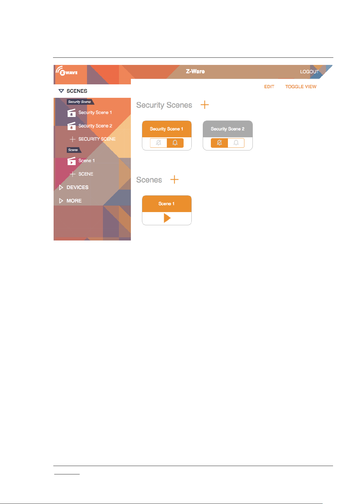
may affect the state of multiple scenes. The “Toggle View” button, only on the Tablet UI, can switch the
scenes arrangement to columns and rows, instead of just 1 column.
Figure 7: Tab UI - Scenes Edit
Page 20
INS14072-5 Z-Ware Web User Guide for SDK v1.11 2018-03-08
silabs.com | Building a more connected world.
Page 14 of 61
Figure 8: Tab UI - Scenes Toggle
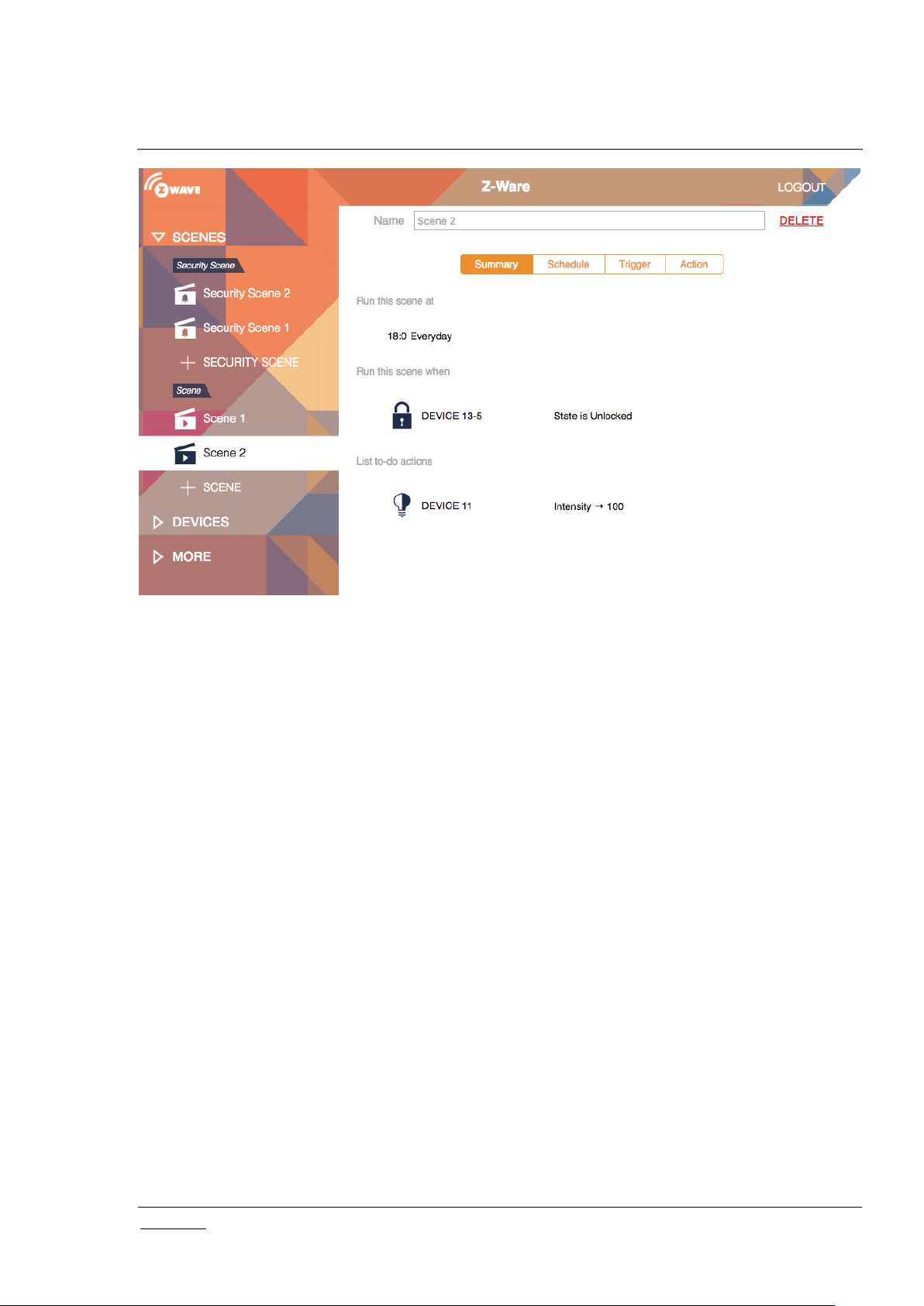
4.1.1 Scene Summary
When a preconfigured scene is viewed by clicking on it or a new scene created by clicking on the ‘+
SCENE’ button, the summary is shown which condenses the associated schedules, triggers and actions
into 1 page. For a new scene these will be empty and would need to be configured. The scene can be
deleted using the DELETE link and renamed in the Name text box. The tabs are for editing and viewing
details for Schedule, Trigger and Action.
Page 21
INS14072-5 Z-Ware Web User Guide for SDK v1.11 2018-03-08
silabs.com | Building a more connected world.
Page 15 of 61
Figure 9: Tab UI: Scene View Summary
4.1.2 Scene Action
When the action tab is clicked, associated actions are shown and may be edited or deleted. If there is
only 1 action, it cannot be deleted until another is added as a scene needs to have at least 1 action.
More actions can be added with the “To do actions +” link, whereby a pop up of device endpoints with
known controllable interfaces will be shown followed by those that can only be controlled via Basic Set.
After the endpoint is selected the interface will need to be selected as well. The value to set can then be
configured on the page itself.
Page 22

INS14072-5 Z-Ware Web User Guide for SDK v1.11 2018-03-08
silabs.com | Building a more connected world.
Page 16 of 61
Figure 10: Tab UI - Scene View Action
4.1.3 Scene Schedule
The Scene schedule tab shows the schedule which can viewed and edited. A schedule is created using
the ‘Run at scheduled time +’ link. The schedule is set to a selected time of day for selected days of the
week, and can be enabled/disabled or deleted.
Figure 11: Tab UI - Scene Schedule
4.1.4 Scene Trigger
The scene trigger tab shows the triggers which can be viewed and edited. The trigger can be enabled,
disabled or deleted.
New triggers can be added with the ‘run this scene when +’ link starting a 3 stage process. Device
endpoints with known reports will be listed in a popup before device endpoints that may only send a
Basic Set. Similar to actions, a device endpoint, interface e.g. multi-level sensor must be selected; and
additionally an interface subtype e.g. temperature sensor. The value for triggering can then be
configured on the page itself.
Page 23

INS14072-5 Z-Ware Web User Guide for SDK v1.11 2018-03-08
silabs.com | Building a more connected world.
Page 17 of 61
Figure 12: Tab UI - Scene Trigger
4.1.5 Security Scene Summary
Similar to a scene, when a security scene is selected or created, the summary page is shown.
4.1.6 Security Scene Arming
When the ‘Arm Automation’ tab is selected.
Figure 13: Tab UI - Security Scene Summary
Page 24

INS14072-5 Z-Ware Web User Guide for SDK v1.11 2018-03-08
silabs.com | Building a more connected world.
Page 18 of 61
Figure 14: Tab UI - Security Scene Arm
4.1.7 Security Scene Disarming
When ‘Disarm Automation’ tab is selected.
4.1.8 Security Scene Alarm
When ‘Alarm’ tab is selected
Figure 15: Tab UI - Security Scene Disarm
Page 25

INS14072-5 Z-Ware Web User Guide for SDK v1.11 2018-03-08
silabs.com | Building a more connected world.
Page 19 of 61
Figure 16: Tab UI - Security Scene Alarm
4.1.9 Security Scene Alarm Popup
When a security scene is triggered, a popup will be shown.
Figure 17: Tab UI - Security Scene Alarm Popup
Page 26

INS14072-5 Z-Ware Web User Guide for SDK v1.11 2018-03-08
silabs.com | Building a more connected world.
Page 20 of 61
4.2 Devices
The Devices menu allows controlling and monitoring of individual devices. Clicking on the devices tab,
lists devices in the network. Z-Wave Inclusion is supported through the ‘+ Add Device’ link. This is also
accessible through the ‘More’ menu and is described there.
Clicking a device lists its interfaces on the larger right panel. The name and location can be changed.
The battery status, if available, will be shown.
‘Show/Hide Details’ will toggle between showing and hiding the Z-Wave Node ID, multichannel endpoint
number, product information and other interfaces that are not graphically represented. The Basic
interface Set is available here as required by Z-Wave Certification requirements although it is not
recommended for common use as it is defined by the end product manual what this will do.
Figure 18: Tab UI - Devices
Page 27

INS14072-5 Z-Ware Web User Guide for SDK v1.11 2018-03-08
silabs.com | Building a more connected world.
Page 21 of 61
Figure 19: Tab UI - Show Details
4.2.1 Binary Sensor Device
The sensor types are shown along with detected or idle.
Figure 20: Tab UI - Binary Sensor
4.2.2 Alarm/Notification Device
Notification types will be grouped and shown with logs of last occurrence of specific events.
Page 28

INS14072-5 Z-Ware Web User Guide for SDK v1.11 2018-03-08
silabs.com | Building a more connected world.
Page 22 of 61
Figure 21: Tab UI – Alarm/Notification Interface Type/Event
4.2.3 Meter Device
4.2.4 Multilevel Sensor Device
Figure 23: Tab UI - Multilevel Sensor Interface
4.2.5 Binary Switch Device
Figure 24: Tab UI - Binary Switch Device
Figure 22: Tab UI - Meter Interface
4.2.6 Dimmer Device
If the device is also a Color Switch, then the color components are shown as well.
Page 29

INS14072-5 Z-Ware Web User Guide for SDK v1.11 2018-03-08
silabs.com | Building a more connected world.
Page 23 of 61
Figure 25: Tab UI - Dimmer (Multilevel Switch Non-Motor) Device
4.2.7 Shades Device
Figure 26: Tab UI - Shades (Multilevel Switch Motor) Device
4.2.8 Door Lock Device
If it supports User Code, it will also be displayed.
Page 30

INS14072-5 Z-Ware Web User Guide for SDK v1.11 2018-03-08
silabs.com | Building a more connected world.
Page 24 of 61
Figure 27: Tab UI - Door Lock Device
4.2.9 Central Scene Controller
Figure 28: Tab UI - Central Scene Controller Device
Page 31

INS14072-5 Z-Ware Web User Guide for SDK v1.11 2018-03-08
silabs.com | Building a more connected world.
Page 25 of 61
4.2.10 Thermostat Device
Figure 29: Tab UI - Thermostat Device
4.2.11 Barrier Operator Device
Figure 30: Tab UI - Barrier Operator Device
4.3 More
The ‘More’ menu provides advanced information and functions in the SmartStart, Maintenance and
About submenus.
Page 32

INS14072-5 Z-Ware Web User Guide for SDK v1.11 2018-03-08
silabs.com | Building a more connected world.
Page 26 of 61
Figure 31: Tab UI – Maintenance (Network)
4.3.1 Maintenance
The ‘Maintenance’ page under the ‘More’ menu supports advanced network functions as shown in Figure
31: Tab UI – Maintenance (Network).
4.3.1.1 Add/Remove Devices (Optionally On Behalf)
This is the Z-Wave include/exclude network operation for non-SmartStart devices. For the Native apps,
there is also the option of scanning the QR code on the device. Devices are automatically named if not
previously named in the Node Naming CC. User may rename them at this point as well.
Figure 32: Tab UI - Add New Device: Initiate
With Z-Wave Security 2, user needs to accept or modify the security class settings. It is recommended
that the user not change the security class settings.
Note: While this operation can be aborted at any time with ‘Cancel’, it is a compound operation that may
perform secure bootstrapping and elaborate device discovery after normal Z-Wave inclusion. So after
abort, the device may still be included but insecurely or with interfaces undiscovered.
Page 33

INS14072-5 Z-Ware Web User Guide for SDK v1.11 2018-03-08
silabs.com | Building a more connected world.
Page 27 of 61
Figure 33: Tab UI - Add New Device: Grant Keys
Additionally for Security 2 Class 1 and 2 devices, the user needs to key in the 1st 5 digits of the DSK,
unless it is scanned in the Native Apps.
With CSA, the user needs to input the controller’s DSK on the device being included instead.
Figure 34: Tab UI - Add New Device: DSK
Figure 35: Tab UI - Add New Device: CSA DSK info
Page 34

INS14072-5 Z-Ware Web User Guide for SDK v1.11 2018-03-08
silabs.com | Building a more connected world.
Page 28 of 61
CC
CC
ASSOCIATION
SENSOR_BINARY
ASSOCIATION_GRP_INFO
SENSOR_MULTILEVEL
BARRIER_OPERATOR
SIMPLE_AV_CONTROL
BATTERY
SWITCH_BINARY
CENTRAL_SCENE
SWITCH_COLOR
CLOCK
SWITCH_MULTILEVEL
CONFIGURATION
THERMOSTAT_FAN_MODE
DOOR_LOCK
THERMOSTAT_FAN_STATE
METER
THERMOSTAT_MODE
METER_TBL_MONITOR
THERMOSTAT_OPERATING_STATE
MULTI_CHANNEL_ASSOCIATION
THERMOSTAT_SETPOINT
NODE_NAMING
USER_CODE
NOTIFICATION/ALARM
VERSION
PROTECTION
The On Behalf button variant is specifically to control the flow for S2 Inclusion Controller CC use case,
such that Z-Ware will know which client will receive the following notifications when the process is started
with the Inclusion Controller and the device to be included or replaced.
4.3.1.2 Reset Network
This is the Z-Wave Set Default network operation and it pops up a confirmation prompt.
4.3.1.3 Update Network
This rediscovers and updates all devices in the network – see 2.1.7
Network Update.
4.3.1.4 Set Learn Mode
This performs the Z-Wave Set Learn Mode network operation. To complete an S2 inclusion, the DSK
may need to be entered on the including Controller.
Figure 36: Tab UI – Set Learn Mode
Page 35

INS14072-5 Z-Ware Web User Guide for SDK v1.11 2018-03-08
silabs.com | Building a more connected world.
Page 29 of 61
4.3.1.5 Broadcast NIF
This broadcasts the attached controller’s Node Information Frame to all nodes in the network.
4.3.1.6 Remove/Replace Failed Devices (Optionally On Behalf)
This is a Z-Wave network function, available from the Device Tab of the Maintenance page, but only
when there is at least one failed node. It pops up a list of devices belonging to failed nodes for removal
or replacement. As with most network operations, it can be aborted. For Replace Failed Node on
Security 2 devices, additional pop ups similar to Add Node will appear.
4.3.1.7 Update Device
This rediscovers and updates the device – see 2.1.6 Node Update.
Figure 37: Tab UI - Replace Failed Device
Page 36

INS14072-5 Z-Ware Web User Guide for SDK v1.11 2018-03-08
silabs.com | Building a more connected world.
Page 30 of 61
4.3.1.8 Send NIF
This sends the attached controller’s Z-Wave Node Information Frame to the device.
4.3.2 SmartStart
On entry, the current provisioning list is shown. Devices can be added to this list using the ‘+’ icon on top
and removed using the bin icon on the left of each device. After clicking on the ‘Edit’ control on the top
right, which then turns to ‘Done’, the device name turns orange clicking which allows editing the device
details. Each device has its status shown on the right and can be ignored by using the status drop down
and selecting ‘ignored’. If a device added to the list is not SmartStart-capable, then it is indicated with a
‘!’ and normal Z-Wave inclusion i.e. ‘Add Device’ will have to be used. For the iOS native version of the
App, adding goes into camera scanning mode for the QR code.
4.3.2.1 Add Device
Figure 38: Tab UI – SmartStart
Figure 39: Tab UI - SmartStart Add Device
Page 37

INS14072-5 Z-Ware Web User Guide for SDK v1.11 2018-03-08
silabs.com | Building a more connected world.
Page 31 of 61
4.3.2.2 Edit Device
Figure 40: Tab UI - SmartStart Edit Device
4.3.2.3 Z-Wave Reset Requirement Detection
If a device added to the provisioning list is detected as already having joined another network, the user is
notified of the same, identifying the device by name if edited or the DSK otherwise.
Figure 41: Tab UI - SmartStart Z-Wave Reset Requirement Detection
4.3.3 About
This submenu provides product, network and user information.
Figure 42: Tab UI - About
Page 38

INS14072-5 Z-Ware Web User Guide for SDK v1.11 2018-03-08
silabs.com | Building a more connected world.
Page 32 of 61
Figure 43: Native Phone UI - Main Page
Figure 44: Native Phone UI – Accounts Page
4.4 Native UI
The Native UI is similar to the Phone/Tab Web UI.
With the More option at the bottom of the Main page, the user can navigate to the Accounts Page tab to
edit the Z-Ware Portal or CE settings.
Page 39

INS14072-5 Z-Ware Web User Guide for SDK v1.11 2018-03-08
silabs.com | Building a more connected world.
Page 33 of 61
5 ENGINEERING UI
The Engineering UI is the most flexible UI, enabling all Z-Wave features.
5.1 Home
After successful login, the user can view on the Home page if the controller has already been initialized.
All web pages have a navigation menu on the left. The home page shows the details of the local
controller.
Figure 45: Eng UI - Home Page
The menu bar on the left is used to navigate to the other pages described in the following chapters. The
user may log out anytime by clicking “Logout” Menu option. “Change Password” Menu option can be
used to change the password which has to be 8 to 16 UTF-8 characters. Resetting the password is done
by the start menu item in Windows or a script in Linux or an application in OS X.
5.2 About
The About page displays the information obtained from the server by using zw_info API. The information
is categorised into two different tables namely General and Version information as shown below.
Figure 46: Eng UI - About Page
Page 40

INS14072-5 Z-Ware Web User Guide for SDK v1.11 2018-03-08
silabs.com | Building a more connected world.
Page 34 of 61
5.3 Network Manager
The Network Manager menu lists nodes in the network and allows network operations like
include/exclude.
The Z-Wave node/vendor/product ID, product types and categories are shown. Further:
Nodes with a lock icon contain at least one secure interface
Non-listening nodes have a ‘zz’ superscript sleep indicator
Failed nodes are shown in red and can be selected for replace/remove failed node operations.
Z-Wave+ information and version information from the node is also displayed at the bottom when the
“>>” icon in the node entry is clicked.
Progress information for all operations is shown to give immediate feedback to the user.
Figure 47: Eng UI - Network Manager Page
Page 41

INS14072-5 Z-Ware Web User Guide for SDK v1.11 2018-03-08
silabs.com | Building a more connected world.
Page 35 of 61
Z-Wave Network Operation
Button(s)
Include nodes
Add Node
Exclude nodes
Remove Node
Include into an existing network
Learn Mode
Factory Reset
Reset
Figure 48: Eng UI - Network operation progress UI
The network operations are similar to what the PC Controller software can do, and therefore will not be
elaborated here. A quick map of operations to buttons is provided below.
Table 10: Z-Wave Network Buttons mapping
Network operation buttons are shown based on the role of the attached controller, for e.g. Add Node will
not show for a secondary controller.
5.3.1 Security 2 Operations
With Security 2, DSK information may need to be entered and security keys granted/accepted.
Page 42

INS14072-5 Z-Ware Web User Guide for SDK v1.11 2018-03-08
silabs.com | Building a more connected world.
Page 36 of 61
Figure 49: Eng UI - S2 Accepting Security Keys
Figure 50: Eng UI - S2 Entering DSK
Page 43

INS14072-5 Z-Ware Web User Guide for SDK v1.11 2018-03-08
silabs.com | Building a more connected world.
Page 37 of 61
5.3.2 Network Health Check
Figure 51: Eng UI - S2 CSA
Figure 52: Eng UI – Network Health Check
5.4 SmartStart
On entry, the current provisioning list is shown. Each node has its status shown on the right. If a device
added to the list is not SmartStart-capable, it is indicated with a ‘!’ icon next to the status and normal ZWave inclusion i.e. ‘Add Device’ will have to be used.
Page 44

INS14072-5 Z-Ware Web User Guide for SDK v1.11 2018-03-08
silabs.com | Building a more connected world.
Page 38 of 61
Figure 53: Eng UI - SmartStart List
Nodes can be added to this list using the ‘Add Device’ button on top. Clicking on the right arrow at the
right of each node allows viewing the details. In the detailed view, the node can be refreshed, deleted or
edited. Adding a node and editing a node lead to the same page. In the edit page, a node in pending
status can be ignored by selecting the ‘ignore’ radio button.
SmartStart nodes in the list that have already joined other networks when detected will cause a ‘device
joined other network’ popup.
Page 45

INS14072-5 Z-Ware Web User Guide for SDK v1.11 2018-03-08
silabs.com | Building a more connected world.
Page 39 of 61
Figure 54: Eng UI - SmartStart Add/Edit Device
Page 46

INS14072-5 Z-Ware Web User Guide for SDK v1.11 2018-03-08
silabs.com | Building a more connected world.
Page 40 of 61
Figure 55: Eng UI – SmartStart Z-Wave Reset Required Detection
5.5 Controller
This page also lists all the nodes in the network. The selected node’s endpoints and device classes; and
the selected endpoint’s interfaces are shown. Endpoints that support Z-Wave Plus are shown with a ‘Z+’
icon. Secure interfaces are shown with a lock icon. Clicking the arrow on the interface tab reveals the
elements within for specific control or monitoring.
Page 47

INS14072-5 Z-Ware Web User Guide for SDK v1.11 2018-03-08
silabs.com | Building a more connected world.
Page 41 of 61
Figure 56: Eng UI - Node Controller Page
Clicking on the “>>” icon on the right of a node provides version information on the firmware and if it is a
FLIRS or Sleeping Device.
Figure 57: Eng UI - Node Version/Info UI
Clicking on the “>>” icon on the right of an endpoint provides any Z-Wave+ information.
Page 48

INS14072-5 Z-Ware Web User Guide for SDK v1.11 2018-03-08
silabs.com | Building a more connected world.
Page 42 of 61
Figure 58: Eng UI - Endpoint Z-Wave+ Info UI
5.6 Interfaces
Most of the interface panels have a cycle icon in middle of the header to refresh the time-stamped state
by soliciting data from the node/endpoint. For more information about each interface, see [5] to [8].
5.6.1 Basic
Figure 59: Eng UI - Basic Interface UI
What Basic CC means/does is device specific and should be documented in the device’s product
manual. Target State and Duration are shown only if the device supports them.
5.6.2 Binary Sensor
Figure 60: Eng UI - Binary Sensor Interface UI
Page 49

INS14072-5 Z-Ware Web User Guide for SDK v1.11 2018-03-08
silabs.com | Building a more connected world.
Page 43 of 61
5.6.3 Multi-Level Sensor
Figure 61: Eng UI - Multilevel Sensor Interface UI
5.6.4 Alarm/Notification
Figure 62: Eng UI – Alarm/Notification Interface UI
Page 50

INS14072-5 Z-Ware Web User Guide for SDK v1.11 2018-03-08
silabs.com | Building a more connected world.
Page 44 of 61
5.6.5 Meter
Figure 63: Eng UI - Meter Interface UI
5.6.6 Battery
Figure 64: Eng UI - Battery Interface UI
5.6.7 Binary Switch
Figure 65: Eng UI - Binary Switch Interface UI
5.6.8 Multi-level Switch
Depending on the CC version, the control elements may vary.
Page 51

INS14072-5 Z-Ware Web User Guide for SDK v1.11 2018-03-08
silabs.com | Building a more connected world.
Page 45 of 61
Figure 66: Eng UI - Multilevel Switch Interface UI
5.6.9 Color Switch Interface
Figure 67: Eng UI - Color Switch Interface
5.6.10 Central Scene Controller
Figure 68:: Eng UI - Central Scene Controller Interface UI
Page 52

INS14072-5 Z-Ware Web User Guide for SDK v1.11 2018-03-08
silabs.com | Building a more connected world.
Page 46 of 61
5.6.11 Door Lock
5.6.12 User Code
Figure 69: Eng UI - Door Lock Interface UI
Figure 70: Eng UI - User Code Interface UI
Page 53

INS14072-5 Z-Ware Web User Guide for SDK v1.11 2018-03-08
silabs.com | Building a more connected world.
Page 47 of 61
5.6.13 Barrier Operator Interface
Figure 71: Eng UI - Barrier Operator Interface UI
5.6.14 Thermostat related interfaces
5.6.14.1 Thermostat Fan
If both the Fan Mode and State interfaces are available in the endpoint, they will be shown combined in a
single frame. Otherwise they will be shown separately.
Figure 72: Eng UI - Thermostat Fan Interface UI
5.6.14.2 Thermostat Mode And Operating State
If both Mode and State interfaces are available in the endpoint, they will be shown combined in a single
frame. Otherwise they will be shown separately.
Page 54

INS14072-5 Z-Ware Web User Guide for SDK v1.11 2018-03-08
silabs.com | Building a more connected world.
Page 48 of 61
Figure 73: Eng UI - Thermostat Mode And State Interface UI
5.6.14.3 Thermostat SetPoint
Figure 74: Eng UI - Thermostat Setpoint Interface UI
5.6.15 Naming/Location
The name/location interface always exists, at least on the local machine, even if the device does not
support the corresponding CC; and is used to set the name/location strings for easier identification. If the
device supports the CC, the name is initialized from the device during inclusion and is only refreshed
after a node update; and setting will set to the device as well.
Page 55

INS14072-5 Z-Ware Web User Guide for SDK v1.11 2018-03-08
silabs.com | Building a more connected world.
Page 49 of 61
Figure 75: Eng UI - Name/Location Interface UI
5.6.16 Association
The user can add or remove node or endpoints (depending on interface support) to any group supported
by the interface limited by its storage.
Group configuration of a node that doesn’t support Association Group Information (AGI) is shown below.
Figure 76: Eng UI - Group Interface UI
Group configuration of a node that supports Association Group Information (AGI) is shown below.
Page 56

INS14072-5 Z-Ware Web User Guide for SDK v1.11 2018-03-08
silabs.com | Building a more connected world.
Page 50 of 61
Figure 77: Eng UI - Group with AGI Interface UI
5.6.17 Configuration
Configuration is a manufacturer specific setting which requires referring to the product manual. ‘Size’ can
be specified explicitly or as the minimum size needed for the given value. Enabling ‘Default’ will ignore
the ‘Value’ and reset the configuration parameter after ‘Set’. ‘Number of parameters’, available only if the
device supports it, allows setting multiple parameters and as many ‘Value’ fields will appear. Enabling
‘Handshake’, available only if the device supports it, will return a report after ‘Set’.
Page 57

INS14072-5 Z-Ware Web User Guide for SDK v1.11 2018-03-08
silabs.com | Building a more connected world.
Page 51 of 61
Figure 78: Eng UI - Configuration Interface UI
5.6.18 Wake up
It is strongly recommended that this controller be set as the notified node. Otherwise it will not be able to
de-queue commands for this node. This is automatically done by Z-Ware. Users are strongly advised
not to change anything on this interface as the newer versions of the underlying ZIPGW expect the
current settings for its mailbox service.
Figure 79: Eng UI - Wakeup Interface UI
5.6.19 Command Queuing
Command queuing is an advanced function that is enabled by default. Only just after including a sleepcapable node, it is to be turned off for configuration and turned on afterwards. Otherwise it is strongly
recommended to leave it on and command queuing works transparently. Also the newer version of
ZIPGW have a mailbox feature which Z-Ware will use instead of its own command queuing capability.
For failure cases e.g. when the controller is not notified on a node’s wake up and the command in the
queue is never removed, this UI allows removal of commands from the queue.
Page 58

INS14072-5 Z-Ware Web User Guide for SDK v1.11 2018-03-08
silabs.com | Building a more connected world.
Page 52 of 61
Figure 80: Command Queuing Interface UI
5.6.20 Firmware Update
Interface to upgrade firmware (Z-Wave chip or others such as a host controller) in the node. This can
also be used to push security certificates and network configurations to the node. The usage of multiple
firmware/targets and checksum are manufacturer dependent and should be found in the relevant
production manual or upgrade documentation.
Limitation: In Portal mode, for devices other than the attached controller, this interface is hidden as
firmware upgrade will be too slow to be practicable owing to the nature of the protocol and end to end
delays.
Limitation: Instead of uploading the firmware files from the web client (browser), these files must be
placed under ‘data’ folder at (platform specific) application data area shown.
Figure 81: Eng UI - Firmware Update Interface UI
5.6.21 Z/IP Gateway
Interface to configure ZIPGW with peer name, peer IP address and peer port number. Unsolicited
destination address and port number can also be configured. ‘Set to Local’ button allows to set the locally
reachable IP address and local listening port number as unsolicited destination.
Page 59

INS14072-5 Z-Ware Web User Guide for SDK v1.11 2018-03-08
silabs.com | Building a more connected world.
Page 53 of 61
Figure 82: Eng UI – ZIPGW Interface Portal Mode UI
Page 60

INS14072-5 Z-Ware Web User Guide for SDK v1.11 2018-03-08
silabs.com | Building a more connected world.
Page 54 of 61
Figure 83: Eng UI - ZIPGW Interface Standalone Mode UI
Page 61

INS14072-5 Z-Ware Web User Guide for SDK v1.11 2018-03-08
silabs.com | Building a more connected world.
Page 55 of 61
5.7 Scenes
Figure 84: Eng UI - Scenes Page
A list of scenes is shown with their activity information. Status can be Active, Inactive or Unknown.
Status for all scenes can be updated by the cycle icon next to the Status header. Scene addition can be
done by “+ Add New Scene” at the foot of the list. Clicking on a scene selects it.
The selected scene is shown in a panel below the list. At the top left of this panel, the pen icon allows
editing; the cross icon allows deletion; the cycle icon allows refreshing the status, while the play icon
executes the scene.
Actions, Schedules and Events are listed in this panel. Actions that match the current state of the device
are shown in Green while others are shown in Orange. Actions with unknown states are shown in default
black.
Page 62

INS14072-5 Z-Ware Web User Guide for SDK v1.11 2018-03-08
silabs.com | Building a more connected world.
Page 56 of 61
The Scene Edit screen looks exactly like the “Add New Scene” screen except that the Scene information
(e.g. Scene name, Actions, Schedules and Events) is already populated.
Any Scene information (including its name) may be changed. The maximum number of actions,
schedules and events allowed are displayed. The Save and Cancel buttons are at the bottom.
At least 1 action is necessary for a valid scene. On the right of every added action is a delete button.
When an endpoint is chosen in the action endpoint list, the candidate interfaces within are listed below
for a SET operation. These include the Basic, Binary/Multi-Level Switch, Door Lock, and Thermostat
SetPoint CCs.
Figure 85: Eng UI - Scene Edit UI
Page 63

INS14072-5 Z-Ware Web User Guide for SDK v1.11 2018-03-08
silabs.com | Building a more connected world.
Page 57 of 61
On the right of every added schedule and event are delete and disable buttons. The disable button turns
into an enable (tick) button when an item is disabled. Disabled schedules and events are shown in
orange and do not trigger a scene even when the conditions specified are met. When an endpoint is
chosen in the event endpoint list, the candidate interfaces within are listed below to respond to a
Binary/Multi-Level Sensor, Door Lock, or Alarm/Notification CC report; or a Basic Set command. Other
than Door Lock, these CCs can support multiple types and these types are listed for selection as well.
5.8 Security Scenes
A list of security scenes is shown with their arm status, and time of change, and last triggered time. The
play icon on the arm and disarm compartments can be used to manually arm or disarm the scene. The
pen and cross icons on the security scene compartment allow editing and deleting the scene.
When editing or creating a security scene, disarm/arm/alarm triggers/scenes can be chosen.
Figure 86: Eng UI - Security Scenes Page
Page 64

INS14072-5 Z-Ware Web User Guide for SDK v1.11 2018-03-08
silabs.com | Building a more connected world.
Page 58 of 61
At the bottom of the page is the notification section where email and/or SMS can be used.
Figure 87: Eng UI - Security Scene Edit UI
Page 65

INS14072-5 Z-Ware Web User Guide for SDK v1.11 2018-03-08
silabs.com | Building a more connected world.
Page 59 of 61
Figure 88: Eng UI - Security Scene Notification Edit UI
Page 66

INS14072-5 Z-Ware Web User Guide for SDK v1.11 2018-03-08
silabs.com | Building a more connected world.
Page 60 of 61
REFERENCES
[1] Silicon Labs, INS14167, INS, Z-Ware Web Developer’s Guide
[2] Silicon Labs, SDS12089, SDS, Z/IP Gateway Bootstrapping
[3] Silicon Labs, APL13031, APL, Z-Wave Networking Basics
[4] Silicon Labs, SDS10242, SDS, Z-Wave Device Class
[5] Silicon Labs, SDS13781, SDS, Z-Wave Application CC
[6] Silicon Labs, SDS13782, SDS, Z-Wave Management CC
[7] Silicon Labs, SDS13783, SDS, Z-Wave Transport-Encapsulation CC
[8] Silicon Labs, SDS13784, SDS, Z-Wave N/W Protocol CC
Page 67

Smart.
Connected.
Energy-Friendly.
Products
www.silabs.com/products
Disclaimer
Silicon Labs intends to provide customers with the latest, accurate, and in-depth documentation of all peripherals and modules available for system and software implementers using or
intending to use the Silicon Labs products. Characterization data, available modules and peripherals, memory sizes and memory addresses refer to each specific device, and "Typical"
parameters provided can and do vary in different applications. Application examples described herein are for illustrative purposes only. Silicon Labs reserves the right to make changes
without further notice and limitation to product information, specifications, and descriptions herein, and does not give warranties as to the accuracy or completeness of the included
information. Silicon Labs shall have no liability for the consequences of use of the information supplied herein. This document does not imply or express copyright licenses granted
hereunder to design or fabricate any integrated circuits. The products are not designed or authorized to be used within any Life Support System without the specific written consent of
Silicon Labs. A "Life Support System" is any product or system intended to support or sustain life and/or health, which, if it fails, can be reasonably expected to result in significant
personal injury or death. Silicon Labs products are not designed or authorized for military applications. Silicon Labs products shall under no circumstances be used in weapons of mass
destruction including (but not limited to) nuclear, biological or chemical weapons, or missiles capable of delivering such weapons.
Trademark Information
Silicon Laboratories Inc.® , Silicon Laboratories®, Silicon Labs®, SiLabs® and the Silicon Labs logo®, Bluegiga®, Bluegiga Logo®, Clockbuilder®, CMEMS®, DSPLL®, EFM®,
EFM32®, EFR, Ember®, Energy Micro, Energy Micro logo and combinations thereof, "the world’s most energy friendly microcontrollers", Ember®, EZLink®, EZRadio®, EZRadioPRO®,
Gecko®, ISOmodem®, Micrium, Precision32®, ProSLIC®, Simplicity Studio®, SiPHY®, Telegesis, the Telegesis Logo®, USBXpress®, Zentri, Z-Wave and others are trademarks or
registered trademarks of Silicon Labs. ARM, CORTEX, Cortex-M3 and THUMB are trademarks or registered trademarks of ARM Holdings. Keil is a registered trademark of ARM Limited.
All other products or brand names mentioned herein are trademarks of their respective holders.
Silicon Laboratories Inc.
400 West Cesar Chavez
Austin, TX 78701
USA
Quality
www.silabs.com/quality
Support and Community
community.silabs.com
http://www.silabs.com
 Loading...