

Page 1

UG350: Silicon Labs Coexistence
Development Kit (SLWSTK-COEXBP)
The Coexistence Development Kit (SLWSTK-COEXBP) is a development kit designed by Silicon Labs to demonstrate coexistence between different radios transmitting in the 2.4 GHz ISM
band. This document revision pertains to revision 3.0 of the
SLWSTK-COEXBP kit. SLWSTK-COEXBP additionally requires
the EFR32™ Mighty Gecko Wireless Starter Kit
(SLWSTK6000B), which contains the following devices:
• 3 x Wireless starter kit (WSTK) mainboard (BRD4001A)
• 3 x EFR32MG12 2.4 GHz 19 dBm radio board (BRD4161A)
• 3 x EFR32MG12 2.4 GHz 10 dBm radio board (BRD4162A)
A Logic Analyzer, to view the logic signals, is optional but recommended.
The software requirements for running the coexistence features are as follows:
• Either the Silicon labs EmberZNet PRO (Zigbee) SDK or the Silicon Labs OpenThread SDK
• Silicon Labs Flex SDK (includes RAIL)
• Software required to run and view logic analyzer waveforms
KEY POINTS
• Describes coexistence hardware and
related software requirements.
• Provides step-by-step instructions for the
installation and configuration of
coexistence features in software.
• Details hardware included in the kit and
how to use it.
• Explains additional software plugins and
packages used for advanced testing.
The software images required to create a Zigbee or OpenThread network with coexistence features enabled must be built through sample applications in the EmberZNet
PRO or OpenThread SDK, with added modifications.
The software required to exercise the coexistence features is available as a custom application built on top of the Flex stack.
This User's Guide refers to Silicon labs EmberZNet PRO release version 6.2.3.0 and
up, Silicon Labs OpenThread release version 1.1.0.0 and up, and Silicon Labs Flex
SDK release version 2.2.2.1 (only).
The following documents are useful resources for understanding Zigbee networks and
coexistence, and will also be referred to in this user's guide:
• AN1017: Zigbee® and Thread Coexistence with Wi-Fi
• QSG106: Zigbee EmberZNet PRO Quick-Start Guide
• QSG170: Silicon Labs OpenThread Quick-Start Guide
silabs.com | Building a more connected world. Rev. 0.4
Page 2
UG350: Silicon Labs Coexistence Development Kit (SLWSTK-COEXBP)
Introduction
1. Introduction
SLWSTK-COEXBP: Silicon Labs Coexistence Development Kit is designed to demonstrate multiple radio coexistence features available as part of the SDK. These features enable radios in a single product (that is, Gateway, Hub, and so on) running on different protocols to arbitrate network traffic to avoid interference. This User Guide details coexistence features in the EmberZNet stack.
A Coexistence test configuration requires the following components:
• Three WSTK boards with either 19 or 10 dBm radio boards mounted, and loaded with the following software images:
• PTA (Packet Traffic Arbitration) Master: Acts as a Wi-Fi emulator and responds to activity on the co-located Z3Light running the
coexistence features.
• Z3Light: Zigbee router/coordinator with coexistence features enabled and connected to the PTA Master.
• Z3Switch: Used to create a network with the Z3Light to generate Zigbee traffic.
• Coexistence Backplane Board
A logic analyzer is optional but highly recommended to enable signal analysis and debugging. In our setup, we use a Saleae logic analyzer.
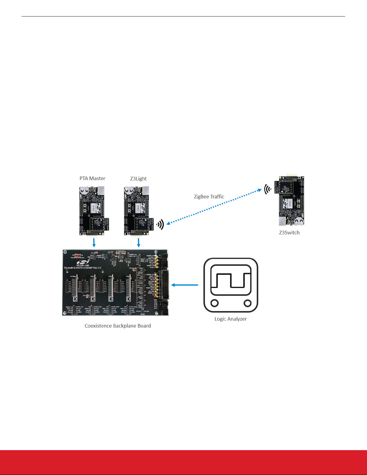
To set up the recommended coexistence test configuration, the PTA Master and Z3Light both are plugged into headers on the Coexistence Backplane Board. The Coexistence Backplane Board has routes between those headers that enable connections between the
two boards. The Coexistence Backplane Board also has routes from the headers to external test points. This allows probing of the signals for debugging and evaluation purposes. The Z3Switch is not plugged into the Coexistence Backplane Board. The recommended
configuration for using the Silicon Labs Coexistence Development Kit is shown in the following figure.
Figure 1.1. Typical Zigbee Coexistence Test Configuration
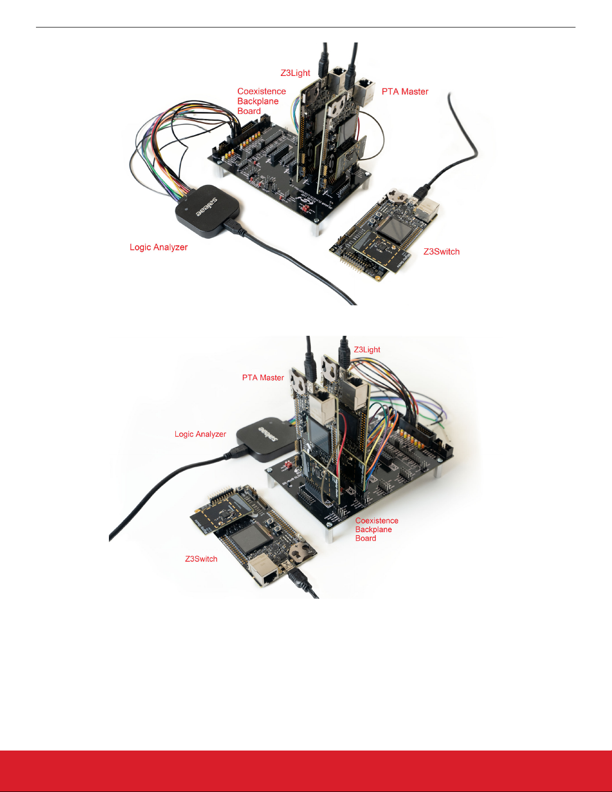
This configuration is shown in the following figures.
silabs.com | Building a more connected world. Rev. 0.4 | 2
Page 3
UG350: Silicon Labs Coexistence Development Kit (SLWSTK-COEXBP)
Introduction
Figure 1.2. Zigbee Coexistence Test Setup (1)
Figure 1.3. Zigbee Coexistence Test Setup (2)
silabs.com | Building a more connected world. Rev. 0.4 | 3
Page 4

UG350: Silicon Labs Coexistence Development Kit (SLWSTK-COEXBP)
Theory of Operation
2. Theory of Operation
This section describes the steps required to bring up a Zigbee network with coexistence features enabled. The section is divided into
multiple subsections detailing each step required. The subsections are:
• 2.1 Bringing Up a Standalone Zigbee Network. Introduces building and flashing the Z3Light and Z3Switch applications, and sending
commands over the network between them.
• 2.2 Adding the Throughput Library to Zigbee Devices. The applications are rebuilt with the throughput library, flashed, and network
traffic created between them.
• 2.3 Adding the Coexistence Feature to Zigbee Devices. Coexistence features are added and the coexistence backplane board is
introduced. Network traffic is created using the throughput library added in the previous step.
• 2.4 Using PTA Master within the Test Setup. The PTA Master application is built and flashed to a device, which then is introduced to
the test setup as a coexistence master device.
• 2.5 Replacing PTA Master with an External Wi-Fi Device. The PTA Master device is replaced with an external Wi-Fi chipset.
Note: This section guides through the steps required to set up coexistence on EFR32MG12-based devices. Refer to section 3.1 Jump-
er Wire Configurations for Different Boards/Devices regarding connection and wiring information for other compatible devices.
2.1 Bringing Up a Standalone Zigbee Network
The first step in setting up for coexistence testing is understanding how to set up a Zigbee network between two devices. For this purpose, we recommend following the steps in QSG106: Getting Started with EmberZNet PRO (QSG106) to build, flash, and verify network commands between the Z3Light and Z3Switch example applications. These applications will be modified and used in subsequent
steps. This allows you to become familiar with application development using the Zigbee stack. It is also important to be familiar with
the steps in QSG106 as the document will be referred to extensively in the following steps. QSG106 can be found through the list of
documents on the Simplicity Studio Launcher perspective, and on the Silicon Labs website under Zigbee documentation. A direct link to
the document is below:
https://www.silabs.com/documents/public/quick-start-guides/qsg106-efr32-zigbee-pro.pdf
2.2 Adding the Throughput Library to Zigbee Devices
This step explains how to modify the example applications to add the throughput library. The throughput library is an additional plugin
available in the EmberZNet PRO stack that allows transmitting data between devices at controllable speeds. It is useful for the evaluation of network quality and connection stability. More information regarding the throughput library can be found in section 4. Throughput
Library.
silabs.com | Building a more connected world. Rev. 0.4 | 4
Page 5
UG350: Silicon Labs Coexistence Development Kit (SLWSTK-COEXBP)
Theory of Operation
2.2.1 Rebuilding and Flashing the Images
1. If you have not already done so in the previous section, follow the steps in QSG106 to start the Z3Light and Z3Switch example
applications. Otherwise return to the Simplicity IDE perspective for one of the examples. If the .isc file is not open, double-click
the .isc file in the Project Explorer to open it.
2. Do not generate the application yet. Additional plugins need to be added.
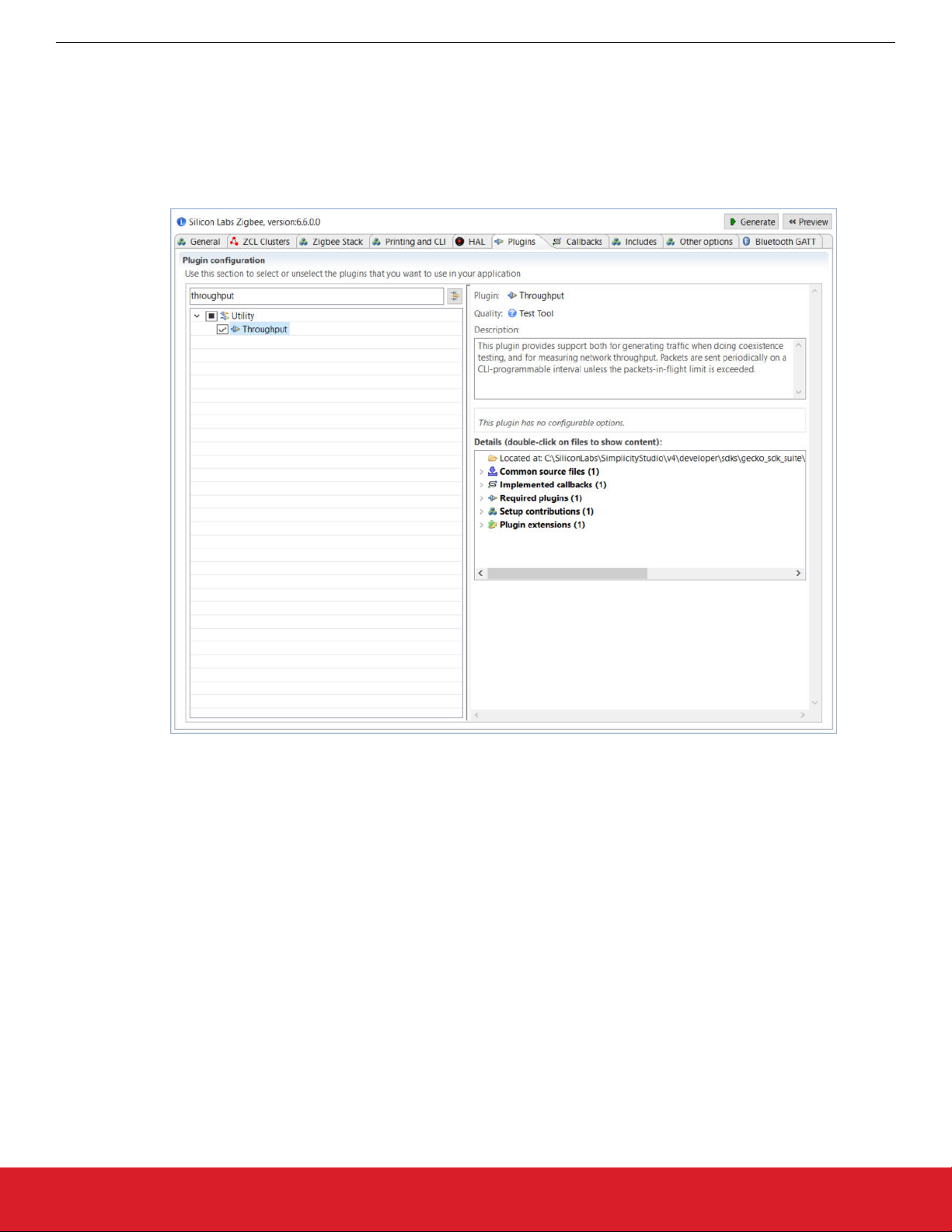
3. Go to the Plugins tab and enter the keyword “throughput” to search for the throughput library plugin.
4. Check the checkbox next to the plugin name to enable the plugin.
Figure 2.1. Enabling the Throughput Plugin
5. Repeat for the other example application.
6. Follow the rest of the steps in QSG106 to generate, build, and flash both the Z3Light and Z3Switch application images.
silabs.com | Building a more connected world. Rev. 0.4 | 5
Page 6

UG350: Silicon Labs Coexistence Development Kit (SLWSTK-COEXBP)
Theory of Operation
2.2.2 Using the Throughput Library to Send Zigbee Traffic
1. From Simplicity studio, access the CLI consoles of the Z3Light and Z3Switch WSTKs. Refer to QSG106 for instructions on opening
CLI consoles.
2. In the console of the Z3Switch example, send the command info to display network information regarding the device. Note the
Node ID in the command's response.
3. In the console of the Z3Light, send the following command
plugin throughput set-all <0xNodeID> 10 10 127 1 0 100000
where NodeID is the node ID of the Z3Switch noted in step 2 above, typed as a hex number. This configures the throughput settings.
4. Still in the console of the Z3Light, send the following command:
plugin throughput start
A series of 10 packets is then sent from the Z3Light to the Z3Switch, generating Zigbee traffic. The Z3Switch console also indicates
packets being received.
More information on the commands used in step 3 and 4 as well as other features of the throughput library can be found in section
4. Throughput Library .
2.3 Adding the Coexistence Feature to Zigbee Devices
This step describes the procedure to enable and configure coexistence features in the example applications. This section uses the
Z3Light application as the example, however the same procedure can be used to enable coexistence on any application. The coexistence features are contained in an additional plugin available in the EmberZNet PRO stack. More information regarding the coexistence
plugin can be found in section 4 of document AN1017: Zigbee® and Thread Coexistence with Wi-Fi.
It is also recommended to enable the FEM driver plugin. This plugin provides visibility into the state of the radio for debugging purposes
and monitoring radio activity.
Note: This procedure assumes you have created, built, flashed, and verified example applications with the Throughput library as described in section 2.2 Adding the Throughput Library to Zigbee Devices.
silabs.com | Building a more connected world. Rev. 0.4 | 6
Page 7
UG350: Silicon Labs Coexistence Development Kit (SLWSTK-COEXBP)
2.3.1 Rebuilding and Flashing the Images
1. Return to the Simplicity IDE perspective for the Z3Light sample application .isc file.
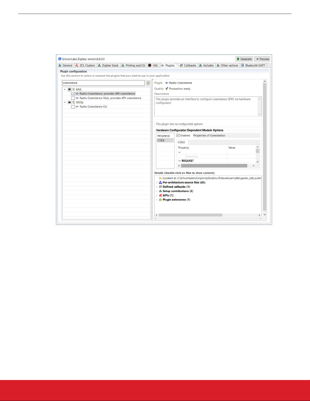
2. Go to the Plugins tab and search for the keyword “coexistence” to find the coexistence configuration plugin.
3. Check the checkbox next to the plugin name to enable the plugin.
Theory of Operation
Figure 2.2. Enabling the Coexistence Configuration Plugin
4. Uncheck the checkbox next to the Stub plugin to disable Stub functions.
5. In the menu on the right, make sure the Enabled box next to Properties of Coexistence is checked.
6. Modify the fields in the menu on the right as follows:
• REQUEST Signal: PC10
• GRANT Signal: PC9
• PRIORITY Signal: PD12
• RHO Signal: Disabled
Leave all other settings with their default values.
7. Still in the Plugins tab, search for keyword “fem” to bring the FEM driver plugin.
silabs.com | Building a more connected world. Rev. 0.4 | 7
Page 8
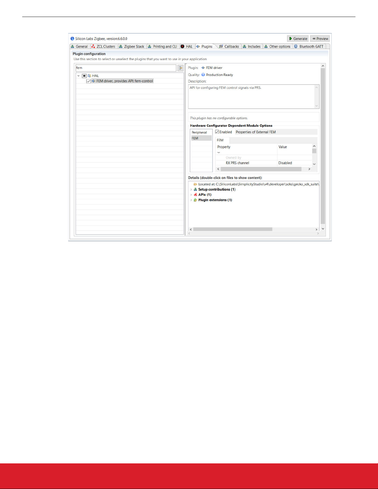
8. Check the checkbox next to the plugin name to enable the plugin.
UG350: Silicon Labs Coexistence Development Kit (SLWSTK-COEXBP)
Theory of Operation
Figure 2.3. Enabling the FEM Driver Plugin
9. In the menu on the right, make sure the Enabled box next to Properties of External FEM is checked.
10. Modify the fields in the menu on the right as follows:
• RX PRS channel: CH6
• PRS channel 6 output pin: PD11
• TX PRS channel: CH5
• PRS channel 5 output pin: PD10
• Enable RX mode: True
• Enable TX mode: True
Leave all other settings with their default values.
11. Repeat for the other example application.
12. Follow the rest of the steps in QSG106 to generate, build, and flash the Z3Light application image.
silabs.com | Building a more connected world. Rev. 0.4 | 8
Page 9
UG350: Silicon Labs Coexistence Development Kit (SLWSTK-COEXBP)
Theory of Operation
2.3.2 Setting up the Coexistence Backplane Board
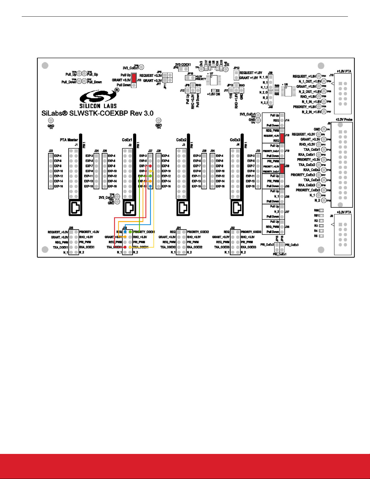
1. Add the appropriate jumper wires and jumpers as shown in the following figure. This sets the GRANT line to always asserted, and
allows the Z3Light to exercise the coexistence signals.
Figure 2.4. Jumper Configurations for Coexistence Testing
2. Plug the Z3Light board into the CoEx1 position (J2) in the Coexistence Backplane board. Follow the silk label for proper orientation.
3. If using a logic analyzer, probe the test points or pins in header J5 (+3.3V probe header) on the right side to access the following
signals:
• REQUEST_+3.3V – TP9 or J5 pin 2
• GRANT_+3.3V – TP10 or J5 pin 4
• PRIORITY_+3.3V – TP14 or J5 pin 12
• TXA_CoEx1 – TP12 or J5 pin 8
• RXA_CoEx1 – TP13 or J5 pin 10
silabs.com | Building a more connected world. Rev. 0.4 | 9
Page 10
UG350: Silicon Labs Coexistence Development Kit (SLWSTK-COEXBP)
Theory of Operation
2.3.3 Using the Throughput Library to Send Zigbee Traffic
1. From Simplicity studio, access the CLI consoles of the Z3Light and Z3Switch WSTKs.
2. In the console of the Z3Switch example, send the command info to display network information regarding the device. Note the
Node ID in the command's response.
3. In the console of the Z3Light, send the following command
plugin throughput set-all <0xNodeID> 10 10 127 1 0 100000
where NodeID is the node ID of the Z3Switch noted in step 2 above, typed as a hex number. This configures the throughput settings.
4. Still in the console of the Z3Light, send the following command:
plugin throughput start
A series of 10 packets is then sent from the Z3Light to the Z3Switch, generating Zigbee traffic. The Z3Switch console also indicates packets being received.
More information on the commands used in step 3 and 4 as well as other features of the throughput library can be found in section
4. Throughput Library.
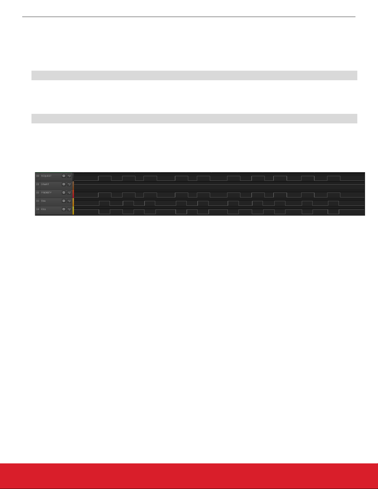
5. Activity corresponding to sending 10 packets can also be observed on the logic analyzer. It will look similar to the following capture.
Figure 2.5. Logic Analyzer Result for Coexistence Testing
REQUEST and PRIORITY signals are asserted 10 times during the throughput run, indicating 10 attempts to send the messages.
In addition, TXA is also asserted within these REQUEST cycles, indicating the radio was transmitting. GRANT signal is always
asserted due to the configuration of the board. The RXA signal is de-asserted when the radio is transmitting, otherwise it remains
asserted representing the radio is in receive mode.
2.4 Using PTA Master within the Test Setup
The PTA master application is a custom application built in the Flex SDK. It is designed to assist in evaluating the coexistence features
available in the stack by acting as a Wi-Fi master device emulator. The PTA master only emulates the GPIO behaviors and cannot
generate actual Wi-Fi traffic. More information regarding the features of the PTA Master can be found in section 5. PTA Master Applica-
tion .
Note: This procedure uses the Z3Light and Z3Switch devices created and installed with the Coexistence Backplane board in the previous procedure.
silabs.com | Building a more connected world. Rev. 0.4 | 10
Page 11
UG350: Silicon Labs Coexistence Development Kit (SLWSTK-COEXBP)
Theory of Operation
2.4.1 Obtaining the PTA Master Application
To obtain the PTA Master application project, you must have the correct version of the Flex SDK (v2.2.2.1) installed. You must also add
the correct board (BRD4161A) to the My Products list in Studio.
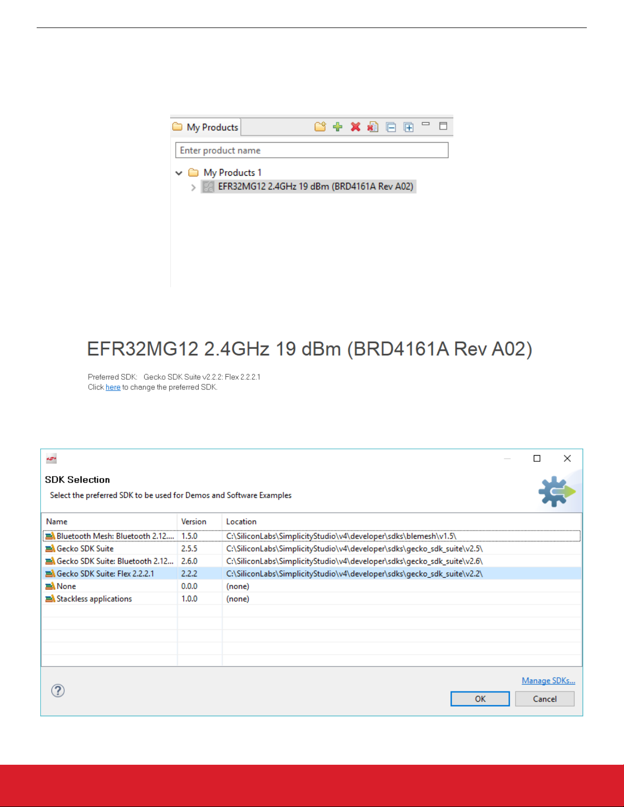
To add the correct board, go to Simplicity Studio's Launcher Perspective, and in the My Products section search for "BRD4161A" and
click it to add it to the list.
Figure 2.6. Selected Board Added to My Products
Next, make sure the Preferred SDK is set to Flex SDK 2.2.2.1.
Figure 2.7. Preferred SDK Selected
If this is not the case, click the here link to change the preferred SDK and select Flex SDK 2.2.2.1. Click [OK].
Figure 2.8. Preferred SDK List
silabs.com | Building a more connected world. Rev. 0.4 | 11
Page 12
UG350: Silicon Labs Coexistence Development Kit (SLWSTK-COEXBP)
Theory of Operation
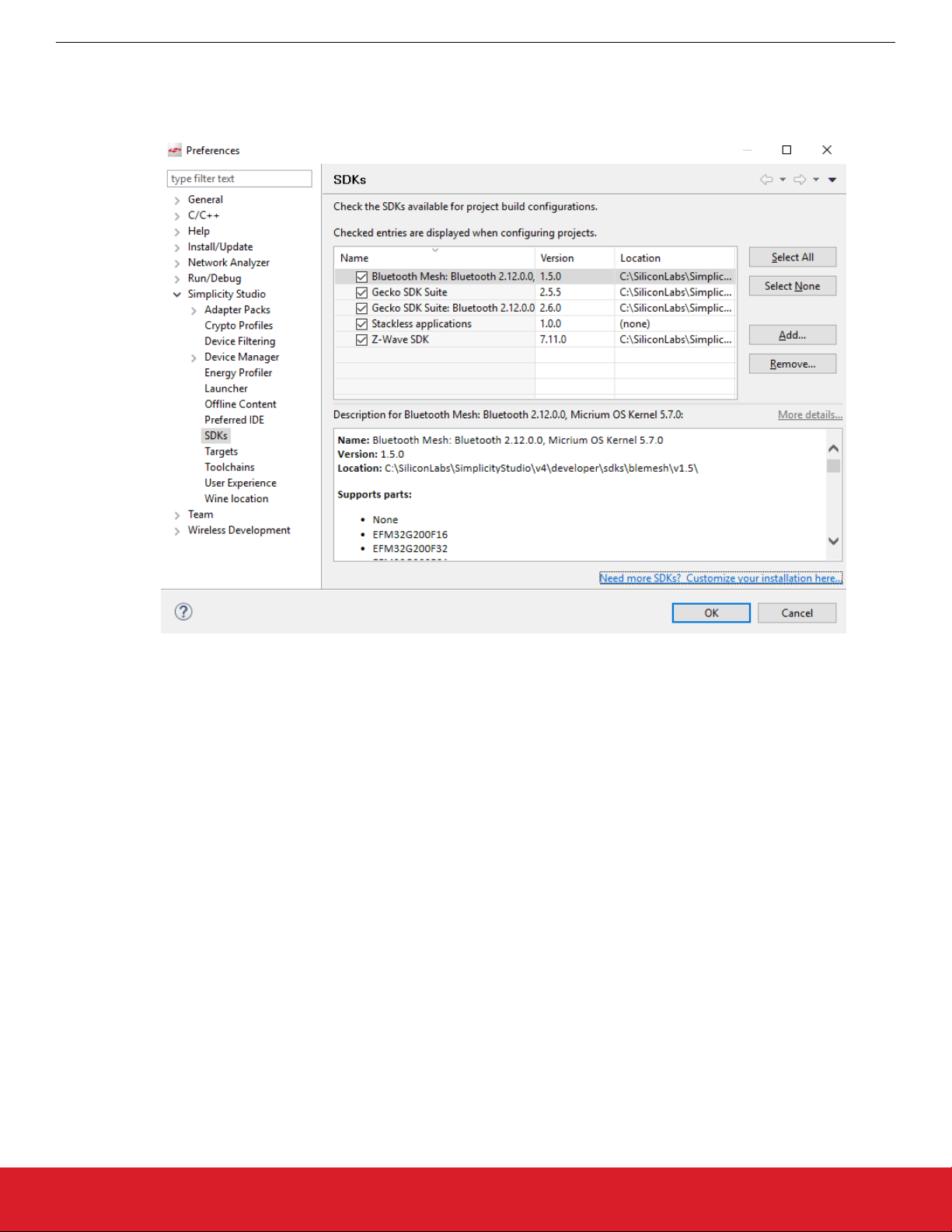
If you do not see Flex 2.2.2.1 on the list, either it is not set as a Preferred SDK, or it is not installed. Click the Manage SDKs link in the
lower right. A list of installed SDKs opens. If you see Flex 2.2.2.1 on the list, make sure the checkbox next to it is checked and click
[OK]. If you do not see it, follow these steps to install it.
1. Click the Need more SDKs? link in the lower right.
2. Click Package Manager.
Figure 2.9. Installed SDKs
silabs.com | Building a more connected world. Rev. 0.4 | 12
Page 13

UG350: Silicon Labs Coexistence Development Kit (SLWSTK-COEXBP)
Theory of Operation
3. Click the SDKs tab. In the Categories drop down, select 'Flex'. In the Version drop down, select 'All'. Scroll down until you see
Flex SDK - 2.2.2.1. Click [Install].
4. When installation is complete, click [Close].
Figure 2.10. SDK Package Manager
silabs.com | Building a more connected world. Rev. 0.4 | 13
Page 14

UG350: Silicon Labs Coexistence Development Kit (SLWSTK-COEXBP)
Theory of Operation
5. You should now see Flex SDK 2.2.2.1 on the list of installed SDKs. It should be checked as available. Click [OK].
Figure 2.11. Installed SDKs with Flex 2.2.2.1
6. Click the here link to change the preferred SDK, select Gecko SDK Suite: Flex 2.2.2.1, and click [OK]. If everything is set correctly, you should see the IoTS PTA Master application in the list of Examples.
Figure 2.12. PTA Master Application in the Examples List
silabs.com | Building a more connected world. Rev. 0.4 | 14
Page 15

UG350: Silicon Labs Coexistence Development Kit (SLWSTK-COEXBP)
Theory of Operation
2.4.2 Building and Flashing the PTA Master Application
Click the PTA Master application shown in the Examples section. You are prompted whether you would like to create the application.
Click [Yes].
Simplicity Studio creates a project with the application, and switches to the Simplicity IDE perspective.
An .isc file also opens. From this point on, the process is similar to that used for previous applications.
Follow the steps in QSG106 to generate, build, and flash the PTA Master application onto one of the boards.
2.4.3 Setting up the PTA Master Device with the Coexistence Backplane Board
1. Remove the jumper from J13 (added to assert GRANT line in Section 2.3.2 Setting up the Coexistence Backplane Board) and add
additional jumper wires required to communicate with the PTA Master, as shown in the following diagram:
Figure 2.13. Jumper Configuration for Coexistence Testing with PTA Master Device
2. Plug PTA Master device into dedicated header J1, on the left side of the board. Make sure the board is oriented according to the
silk near the header.
2.4.4 Configuring the PTA Master Application to Work With Z3Light
The PTA Master application features run-time configurable options to configure the behavior. By default, all additional features are
turned off, and all signals are assumed active High.
Therefore, the PTA Master will work with the Z3Light device as is, without needing additional configurations. Details regarding additional configurations can be found in section 5. PTA Master Application.
silabs.com | Building a more connected world. Rev. 0.4 | 15
Page 16

UG350: Silicon Labs Coexistence Development Kit (SLWSTK-COEXBP)
Theory of Operation
2.4.5 Using the Throughput Library to Send Zigbee Traffic
1. From Simplicity studio, access the CLI consoles of the Z3Light and Z3Switch WSTKs.
2. In the console of the Z3Switch example, send the command info to display network information regarding the device. Note the
Node ID in the command's response.
3. In the console of the Z3Light, send the following command:
plugin throughput set-all <0xNodeID> 10 10 127 1 0 100000
where NodeID is the node ID of the Z3Switch noted in step 2 above, typed as a hex number. This configures the throughput settings.
4. Still in the console of the Z3Light, send the following command:
plugin throughput start
A series of 10 packets is then sent from the Z3Light to the Z3Switch, generating Zigbee traffic. The Z3Switch console also indicates packets being received.
More information on the commands used in step 3 and 4 as well as other features of the throughput library can be found in section
4. Throughput Library.
5. Activity corresponding to sending 10 packets can also be observed on the logic analyzer. It will look similar to the following capture.
Figure 2.14. Logic Capture for Coexistence Testing with PTA Master Device
REQUEST and PRIORITY signals are asserted 10 times during the throughput run, indicating 10 attempts to send the messages.
Note here that the GRANT signal controlled by PTA Master is also asserted and de-asserted with REQUEST. In default settings,
the PTA Master is configured to always GRANT when the slave REQUESTs. In addition, TXA is also asserted within these REQUEST cycles, indicating the radio was transmitting. The RXA signal is de-asserted when the radio is transmitting, otherwise it
remains asserted representing the radio is in receive mode.
2.5 Replacing PTA Master with an External Wi-Fi Device
Once evaluation has been completed using the PTA Master application, the next step is to use an actual external Wi-Fi chipset to interface with the coexistence features in the Z3Light device. The following steps detail how this can be achieved.
1. Remove the PTA Master device.
2. Connect the external Wi-Fi device coexistence signals to the appropriate header.
• If using a +3.3V signals Wi-Fi device, use header J8.
• If using a +1.8V signals Wi-Fi device, use header J10.
Refer to section 3. Coexistence Backplane Board for more detail.
3. The PTA signals are routed from the CoEx plugin headers to the probe headers J8 and J10 when configured to be used, so the WiFi device should be able to receive and respond to the signal states.
silabs.com | Building a more connected world. Rev. 0.4 | 16
Page 17

UG350: Silicon Labs Coexistence Development Kit (SLWSTK-COEXBP)
Coexistence Backplane Board
3. Coexistence Backplane Board
This section gives a detailed explanation of the Coexistence Backplane Board. The board is compatible with all EFR32MG1x series
devices. Table 3.1 Jumper Wire Recommendations for PTA on Different Devices on page 17 shows recommended PTA pin selections for different supported boards.
Note: Due to GPIO limitations on some boards, GPIOs routed to peripherals on the WSTK may need to be used for PTA functions. This
requires that the peripheral configurations be disabled in the hardware configuration. Instructions on how to achieve this are in section
3.1.1 Disabling Peripheral Functionality.
For BRD4169: Button and LED peripherals need to be disabled.
For BRD4180: Button, LED, and UART RTS/CTS need to be disabled.
Other radio boards do not require any peripherals to be disabled.
3.1 Jumper Wire Configurations for Different Boards/Devices
Table 3.1. Jumper Wire Recommendations for PTA on Different Devices
Board/Device REQUEST (EXP/GPIO) GRANT (EXP/GPIO) PRIORITY (EXP/GPIO) RHO (EXP/GPIO)
BRD4151/EFR32MG1P EXP15/PC10 EXP13/PF3 EXP11/PD12 EXP16/PC11
BRD4161/EFR32MG12P EXP15/PC10 EXP13/PC9 EXP11/PD12 EXP16/PC11
BRD4168/EFR32MG13P EXP15/PC10 EXP13/PF3 EXP11/PD12 EXP16/PC11
BRD4169/EFR32MG14P EXP15/PC10 EXP13/PF3 EXP10/PC9 EXP16/PC11
BRD4180/EFRMG21 EXP11/PB00 EXP6/PC01 EXP13/PB01 Not supported
It is also helpful to observe the FEM control signals, and the recommended pins for different boards are shown in the following table.
Table 3.2. Jumper Wire Recommendations for Radio State on Different Devices
Board/Device TX PRS Channel TX (EXP/GPIO) RX PRS Channel RX (EXP/GPIO)
BRD4151/EFR32MG1P CH5 EXP7/PD10 CH6 EXP9/PD11
BRD4161/EFR32MG12P CH5 EXP7/PD10 CH6 EXP9/PD11
BRD4168/EFR32MG13P CH5 EXP7/PD10 CH6 EXP9/PD11
BRD4169/EFR32MG14P CH2 EXP7/PF6 CH3 EXP9/PF7
BRD4180/EFRMG21 CH8 EXP7/PD02 CH9 EXP9/PD03
For jumper positions for different coexistence configurations, refer to section 3.2 Configuring for Different PTA Scenarios.
silabs.com | Building a more connected world. Rev. 0.4 | 17
Page 18

UG350: Silicon Labs Coexistence Development Kit (SLWSTK-COEXBP)
3.1.1 Disabling Peripheral Functionality
1. In the project .isc file, select the HAL configuration tab and click [Open Hardware Configurator].
Coexistence Backplane Board
Figure 3.1. Open Hardware Configurator
This opens a new tab with the Configurator perspective active.
2. Click the DefaultMode Peripherals tab to open a list of enabled configurators.
silabs.com | Building a more connected world. Rev. 0.4 | 18
Page 19

UG350: Silicon Labs Coexistence Development Kit (SLWSTK-COEXBP)
Coexistence Backplane Board
3. To disable LED and Button peripherals, uncheck the checkboxes next to LED and/or Button, and click [Save] (or press Ctrl+S).
The hal-config.h file will be automatically updated with the latest changes.
Figure 3.2. Disable Button and LED Configurations
silabs.com | Building a more connected world. Rev. 0.4 | 19
Page 20

UG350: Silicon Labs Coexistence Development Kit (SLWSTK-COEXBP)
Coexistence Backplane Board
4. To disable the USART CTS/RTS support, select the USART0 box under Peripherals, and modify the properties as follows:
Flow Control Mode: No flow control
USART CTS pin: Disabled
USART RTS pin: Disabled
Click [Save] (or press Ctrl+S). The hal-config.h file will be automatically updated with the latest changes.
Figure 3.3. Disable USART CTS/RTS Support
5. Once all changes have been saved, rebuild project using instructions in QSG106: Getting Started with EmberZNet PRO.
silabs.com | Building a more connected world. Rev. 0.4 | 20
Page 21

UG350: Silicon Labs Coexistence Development Kit (SLWSTK-COEXBP)
Coexistence Backplane Board
3.2 Configuring for Different PTA Scenarios
3.2.1 Single-EFR32 Radio
For a single EFR32 radio, be sure to:
1. Configure Board jumpers and jumper wires as follows. Make sure the jumper wire selections are based off the board and device
being used. Refer to Table 3.1 Jumper Wire Recommendations for PTA on Different Devices on page 17 and Table 3.2 Jumper
Wire Recommendations for Radio State on Different Devices on page 17 for details.
Figure 3.4. Coexistence Backplane Board Jumpers for Single-EFR32 Radio
2. Develop the desired PTA test application using AppBuilder.
3. Add the coexistence-configuration plugin and configure for target Wi-Fi/PTA device as per single-radio description (see the section
“PTA Support Software Setup” in AN1017: Zigbee® and Thread Coexistence with Wi-Fi).
4. Add FEM driver plugin (configured as described above) to enable TXA and RXA observation.
5. Build the EFR32 application and program the WSTK.
6. Plug the EXP header on the EFR32/WSTK Board into Coexistence Backplane Board CoEx1 header (J2) (ensure pin 1 to pin 1).
7. Enable PTA on the Wi-Fi/PTA device.
8. Execute Wi-Fi stream and 802.15.4 stream.
9. Observe Wi-Fi error rate and 802.15.4 message success.
10. Observe PTA signals to debug, and adjust as necessary.
11. With the PTA solution confirmed, the coexistence-plugin only needs to be modified for the PTA GPIOs assigned on target hardware.
silabs.com | Building a more connected world. Rev. 0.4 | 21
Page 22

UG350: Silicon Labs Coexistence Development Kit (SLWSTK-COEXBP)
Coexistence Backplane Board
3.2.2 Multi-EFR32 Radios with Unshared PRIORITY
For multi- EFR32 radios with unshared PRIORITY, be sure to do the following:
1. Configure Board jumpers and jumper wires as follows. If using two radios, do not configure jumper wires for Coex 3. Make sure the
jumper wire selections are based off the board and device being used. Refer to Table 3.1 Jumper Wire Recommendations for PTA
on Different Devices on page 17 and Table 3.2 Jumper Wire Recommendations for Radio State on Different Devices on page 17
for details.
Figure 3.5. Coexistence Backplane Board Jumpers for Multi-EFR32 Radios with Unshared PRIORITY
2. Develop desired PTA test applications using AppBuilder.
3. Add coexistence-configuration plugins and configure for target Wi-Fi/PTA device as per multi-radio description (see the section
“PTA Support Software Setup” in AN1017: Zigbee® and Thread Coexistence with Wi-Fi).
4. Add the FEM driver plugin (configured as described above) to enable TXA and RXA observation.
5. Build the EFR32 applications and program the WSTKs.
6. Plug the EXP header on one EFR32/WSTK Board into Coexistence Backplane Board CoEx1 header (J2) and the second and third
EFR32/WSTK Boards, if used, into CoEx2 and CoEx3 headers (J3 and/or J4) (ensure pin 1 to pin 1).
7. Enable PTA on the Wi-Fi/PTA device.
8. Execute Wi-Fi stream and 802.15.4 streams.
9. Observe Wi-Fi error rate and 802.15.4 message success.
10. Observe PTA signals to debug and adjust as necessary.
11. With the PTA solution confirmed, the coexistence-plugin only needs to be modified for the PTA GPIOs assigned on target hardware.
silabs.com | Building a more connected world. Rev. 0.4 | 22
Page 23

UG350: Silicon Labs Coexistence Development Kit (SLWSTK-COEXBP)
Coexistence Backplane Board
3.2.3 Multi-EFR32 Radios with Shared PRIORITY
For multi-EFR32 radios with shared PRIORITY, be sure to do the following.
1. Configure Board jumpers and jumper wires as follows. If using 2 radios, do not configure jumper wires for Coex 3. Make sure the
jumper wire selections are based off the board and device being used. Refer to Table 3.1 Jumper Wire Recommendations for PTA
on Different Devices on page 17 and Table 3.2 Jumper Wire Recommendations for Radio State on Different Devices on page 17
for details.
Figure 3.6. Coexistence Backplane Board Jumpers for Multi-EFR32 Radios with Shared PRIORITY
2. Develop desired PTA test applications using AppBuilder.
3. Add coexistence-configuration plugins and configure for target Wi-Fi/PTA device as per multi-radio description (see the section
“PTA Support Software Setup” in AN1017: Zigbee® and Thread Coexistence with Wi-Fi).
4. Add the FEM driver plugin (configured as described above) to enable TXA and RXA observation.
5. Build the EFR32 applications and program the WSTKs.
6. Plug the EXP header on one EFR32/WSTK Board into Coexistence Backplane Board CoEx1 header (J2) and the second and third
EFR32/WSTK Boards, if used, into CoEx2 and CoEx3 headers (J3 and/or J4) (ensure pin 1 to pin 1).
7. Enable PTA on the Wi-Fi/PTA device.
8. Execute Wi-Fi stream and 802.15.4 streams.
9. Observe Wi-Fi error rate and 802.15.4 message success.
10. Observe PTA signals to debug and adjust as necessary.
11. With the PTA solution confirmed, the coexistence-plugin only needs to be modified for the PTA GPIOs assigned on target hardware.
3.2.4 PWM Feature
Refer to AN1017: Zigbee® and Thread Coexistence with Wi-Fi on how to set up the board to use the PWM feature.
3.3 I/O to Wi-Fi/PTA Devices for +3.3V or +1.8V
The Coexistence Backplane Board provides the capability of interfacing to Wi-Fi/PTA devices via +3.3 V or +1.8 V I/O as needed.
silabs.com | Building a more connected world. Rev. 0.4 | 23
Page 24

UG350: Silicon Labs Coexistence Development Kit (SLWSTK-COEXBP)
Coexistence Backplane Board
3.3.1 I/O for +3.3V
For +3.3 V I/O to Wi-Fi/PTA device, PTA signal connections to Wi-Fi/PTA should be made to J8 as shown in the following table. Add
appropriate jumpers and jumper wires based on device configuration explained in section 3.2 Configuring for Different PTA Scenarios.
Figure 3.7. Coexistence Backplane Board Jumpers for +3.3V I/O Operation
The +3.3V /IO connections to Wi-Fi/PTA device can be made via +3.3V PTA HDR (J8) as follows:
Table 3.3. Header (J8) Pins for +3.3V I/O Connections
EFR32 PTA Signal J8 Pin
REQUEST_+3.3V 1
GRANT_+3.3V 3
RHO_+3.3V 5
PRIORITY_+3.3V 7
GND 9 and 10
Note: Additional jumpers are required to configure the REQUEST and PRIORITY signals. Jumper configuration varies with singleEFR32 radio and multi-EFR32 radio configurations and active-high/active-low polarities. See section 3.2 Configuring for Different PTA
Scenarios for these jumper options.
silabs.com | Building a more connected world. Rev. 0.4 | 24
Page 25

UG350: Silicon Labs Coexistence Development Kit (SLWSTK-COEXBP)
Coexistence Backplane Board
3.3.2 I/O for +1.8V
For +1.8V I/O to Wi-Fi/PTA device, (assuming typical 3-Wire PTA with RHO unused), PTA signal connections to Wi-Fi/PTA should be
made to J10 and all red jumpers shown below are required. Add additional jumpers and jumper wires based on device configuration
explained in section 3.2 Configuring for Different PTA Scenarios.
Figure 3.8. PTA Backplane Board Jumpers for +1.8V I/O Operation
The +1.8 V /IO connections to Wi-Fi/PTA device can be made via +1.8 V PTA HDR (J10) as follows:
Table 3.4. Header (J10) Pins for +1.8V I/O Connections
EFR32 PTA Signal J10 Pin
REQUEST_+1.8V 1
GRANT_+1.8V 3
RHO_+1.8V
5
(If RHO is used, move J11/JP13 jumper and add J8/J12 jumper)
PRIORITY_+1.8V 7
GND 9 and 10
Note: Additional jumpers are required to configure the REQUEST and PRIORITY signals. Jumper configuration varies with singleEFR32 radio and multi-EFR32 radio configurations and active-high/active-low polarities. See section 3.2 Configuring for Different PTA
Scenarios for these jumper options.
silabs.com | Building a more connected world. Rev. 0.4 | 25
Page 26

UG350: Silicon Labs Coexistence Development Kit (SLWSTK-COEXBP)
Coexistence Backplane Board
3.4 Probe Header
The EFR32 PTA signals (+3.3V I/O) are observable via a logic analyzer connected to J5 as shown below:
Figure 3.9. Coexistence Backplane Board Header for PTA Signal Logic Analyzer Connection
Where:
• CoEx1 refers to EFR32/WSTK connected into CoEx1 header (J2)
• CoEx2 refers to EFR32/WSTK connected into CoEx2 header (J3)
• CoEx3 refers to EFR32/WSTK connected into CoEx3 header (J4)
Note: Depending on jumper configurations, PRIORITY_+3.3 V can be PRIORITY_CoEx1 or wired-OR/-AND of multiple PRIORITY
signals. See section 3.2 Configuring for Different PTA Scenarios for these PRIORITY_+3.3 V jumper options.
silabs.com | Building a more connected world. Rev. 0.4 | 26
Page 27

3.5 Board Schematics
UG350: Silicon Labs Coexistence Development Kit (SLWSTK-COEXBP)
Coexistence Backplane Board
Figure 3.10. SLWSTK-COEXBP Schematic (1/3)
silabs.com | Building a more connected world. Rev. 0.4 | 27
Page 28

UG350: Silicon Labs Coexistence Development Kit (SLWSTK-COEXBP)
Coexistence Backplane Board
Figure 3.11. SLWSTK-COEXBP Schematic (2/3)
silabs.com | Building a more connected world. Rev. 0.4 | 28
Page 29

UG350: Silicon Labs Coexistence Development Kit (SLWSTK-COEXBP)
Coexistence Backplane Board
Figure 3.12. SLWSTK-COEXBP Schematic (3/3)
silabs.com | Building a more connected world. Rev. 0.4 | 29
Page 30

UG350: Silicon Labs Coexistence Development Kit (SLWSTK-COEXBP)
Coexistence Backplane Board
3.6 Packet Trace
For the purposes of debugging, it can useful to monitor the packet trace (PTI) signals generated by the radio device. These signals,
when viewed with TXA and RXA to indicate radio state, can help determine when a packet was received or transmitted, and whether
the radio transaction was successful. To access the PTI signals, some modifications need to be made to the coexistence device’s
WSTK board.
1. Solder a header into the pin locations currently marked as NC. These pins are not connected to any functions on the WSTK board.
It is also recommended to add header pins to the adjacent GND pin locations to provide proper ground reference to the logic analyzer.
Figure 3.13. PTI Header Location
2. Solder wires to pin 32 and pin 33 of the 40-pin connector. Pin 32 corresponds to the PTI_Frame/PTI_Sync signal, and Pin 33 corresponds to the PTI_DATA signal.
Figure 3.14. PTI Pin Locations
silabs.com | Building a more connected world. Rev. 0.4 | 30
Page 31

UG350: Silicon Labs Coexistence Development Kit (SLWSTK-COEXBP)
Coexistence Backplane Board
3. Route these wires to the back of the board and solder onto the header pins that are in the NC pin locations.
Figure 3.15. PTI Header Soldering
4. Connect a logic analyzer to the two PTI signals.
The logic analyzer will now be able to capture Packet Trace information alongside coexistence activity from the radio.
Figure 3.16. PTI Logic Capture
For information on how to analyze the PTI data captured, refer to AN1017: Zigbee® and Thread Coexistence with Wi-Fi or contact the
Silicon Labs support team.
silabs.com | Building a more connected world. Rev. 0.4 | 31
Page 32

UG350: Silicon Labs Coexistence Development Kit (SLWSTK-COEXBP)
4. Throughput Library
4.1 Throughput Library Commands
Table 4.1. List of Commands Available in the Throughput Library
Command Command Description Arguments
Name Type Description
plugin
throughput
start
plugin
throughput
stop
plugin
throughput
print-result
Start the throughput test
Abort the test while running
Show the results of the last test
Throughput Library
plugin
throughput
set-destination
plugin
throughput
set-interval
plugin
throughput
set-timeout
plugin throughput
set-count
plugin
throughput
set-inflight
plugin
throughput
set-packet-size
plugin
throughput
set-all
Set the destination nodeId nodeId INT16U Destination nodeId
Set the interval interval INT16U Interval in ms
Set the test timeout timeout INT32U Timeout in ms
Set the number of packets to send count INT16U Packets to send
Set the number of packets in flight during the test inflight_count INT8U Packets in flight
Set the packet length packet INT8U Packet length in bytes
nodeId INT16U Destination nodeId
Set all parameters:
• NodeID
• Count
• Interval
• Packet Length
• Max In-Flight
• APS Options
count INT16U Packets to send
interval INT16U Interval in ms
packet INT8U Packet length in bytes
inflight_count INT8U Packets in flight
apsOptions INT16U APS Options
• Test Timeout
timeout INT32U Timeout in ms
silabs.com | Building a more connected world. Rev. 0.4 | 32
Page 33

UG350: Silicon Labs Coexistence Development Kit (SLWSTK-COEXBP)
Command Command Description Arguments
Name Type Description
plugin
throughput
set-aps-ack-off
plugin
throughput
set-aps-ack-on
plugin
throughput
print-parameters
plugin
throughput
print-counters
plugin
throughput
clear-counters
Turn off APS acks
Turn on APS acks
Print all the test parameters
Print the stack counters
Clear all the stack counters
Throughput Library
silabs.com | Building a more connected world. Rev. 0.4 | 33
Page 34

UG350: Silicon Labs Coexistence Development Kit (SLWSTK-COEXBP)
Throughput Library
4.2 Using the Throughput Library
To begin using the throughput library, the required parameters need to be defined. The simplest way to achieve this is by using command “plugin throughput set-all <parameters>”. Details regarding the command and order of parameters can be found in Table 4.1 List
of Commands Available in the Throughput Library on page 32.
A sample command is plugin throughput set-all <0xNodeID> 10 0 127 1 0 100000, where NodeID needs to be defined as the
nodeID of the receiving node, typed as a hex number. Note: to achieve maximum throughput, the interval field should to be set to 0.
To print the parameters currently set, use the command plugin throughput print-parameters. This returns the parameters currently defined, in the following format:
TEST PARAMETERS
Destination nodeID: 0x1234
Packets to send: 10
Transmit interval: 0 ms
Payload size: 77B
Packet size: 127B
Packets in flight: 1
APS Options = 0x0000
Timeout: 100000 ms
To start the throughput process, use the command plugin throughput start. This starts sending packets to the other device. To
stop the test during the run, use command plugin throughput stop. Once the test is complete, you can print the results using
plugin throughput print-result. This produces the results of the most recent run, in the following format:
THROUGHPUT RESULTS
Total time 96 ms
Success messages: 10 out of 10
Payload Throughput: 64166 bits/s
Phy Throughput: 105833 bits/s
Min packet send time: 6 ms
Max packet send time: 8 ms
Avg packet send time: 6 ms
STD packet send time: 2 ms
The throughput is calculated by dividing the total number of bits sent by the total time.
For Phy Throughput:
For Payload Throughput:
The throughput plugin also tracks some counters to provide visibility and help with debugging purposes. Use plugin throughput
print-counters. The results are produced in the following format:
COUNTERS
CCA Failures: 0
Mac Tx Ucast: 10
Mac Tx Ucast Retry: 0
Mac Tx Ucast Fail: 0
APS Tx Ucast Success: 10
APS Tx Ucast Retry: 0
APS Tx Ucast Fail: 0
Details regarding the MAC and APS stack counters can be found in AN1017: Zigbee® and Thread Coexistence with Wi-Fi and are also
documented in the stack API documentation.
silabs.com | Building a more connected world. Rev. 0.4 | 34
Page 35

UG350: Silicon Labs Coexistence Development Kit (SLWSTK-COEXBP)
PTA Master Application
5. PTA Master Application
The PTA Master application is custom application built on the Flex stack, designed to help customers evaluate coexistence features on
the silicon labs devices. The Zigbee radios act as slave devices, and require a master device to react and respond to coexistence requests. The PTA Master application implements this and allows users control to the behavior of the PTA Master to evaluate the corresponding behavior of the slave device.
5.1 Commands in the PTA Master Application
Table 5.1. List of Commands Available in the PTA Master Application
Command Command Description Argument and Description
configuration Print out the current configuration of features
request Set REQUEST signal polarity
grant Set GRANT signal polarity
priority Set PRIORITY signal polarity
rho Set RHO signal polarity
grantabort
grantdelay
grantdeny
Enable/Disable GRANT Abort feature, and
set abort percentage
Enable/Disable GRANT Delay feature, and
set delay percentage
Enable/Disable GRANT Deny feature, and
set deny percentage
activehigh: sets the signal polarity active HIGH
activelow: sets the signal polarity active LOW
activehigh: sets the signal polarity active HIGH
activelow: sets the signal polarity active LOW
activehigh: sets the signal polarity active HIGH
activelow: sets the signal polarity active LOW
activehigh: sets the signal polarity active HIGH
activelow: sets the signal polarity active LOW
0: disables GRANT Abort
1-100: enables GRANT Abort and sets percentage of GRANTS
that are aborted
0: disables GRANT Delay
1-100: enables GRANT Delay and sets percentage of
GRANTS that are delayed
0: disables GRANT Deny
1-100: enables GRANT Deny and sets percentage of GRANTS
that are denied
rhofeature
Enable/Disable Radio Hold Off (RHO) feature, and set rho percentage
1-100: enables RHO and sets percentage of Radio Hold Off requests
Output a toggling stream for a specified time,
up to 60 seconds.
0: disables RHO feature, and sets pin to High Z mode.
txStreamToggling
1-60: time for which to output stream
Note: This feature sets GRANT to always asserted
1: Enable stream
setTxStream Output a stream
0: Disable stream
setPower
getPower Get the current transmit power in deci dBm
setchannel Set the current radio channel 0-15: Value 0 corresponds to Zigbee channel 11
getchannel Get the current radio channel
silabs.com | Building a more connected world. Rev. 0.4 | 35
Set the current transmit power in deci dBm,
or raw units if 'raw' is specified
Output power to set (range depends on capabilities of radio device. Refer to datasheet of device for more info)
Page 36

UG350: Silicon Labs Coexistence Development Kit (SLWSTK-COEXBP)
PTA Master Application
5.2 Using the PTA Master Application
The PTA Master application is ready to use after compilation with the following default features:
• REQUEST is set to Active HIGH
• GRANT is set to Active HIGH
• PRIORITY is set to Active HIGH
• RHO is set to Active HIGH, but the feature is disabled and the pin is set to High Z mode
• GRANT Abort, GRANT Delay, and GRANT Deny are disabled
• No stream is active
To change any of the default configurations, use the commands previously listed.
Use the configuration command to print out current configuration. An example output returned through the CLI is:
Request: Active High
Grant: Active High
Priority: Active High
Radio Hold Off: Active High
Grant Abort: Disabled
Grant Delay: Disabled
Grant Deny: Disabled
RHO Feature: Disabled
The PTA Master application can also hinder network traffic to test behavior of the slave device in such conditions. The
txStreamToggling command outputs a periodic stream for a specified time, causing packets or sections of packets on the network to
get corrupted.
silabs.com | Building a more connected world. Rev. 0.4 | 36
Page 37

Smart.
Connected.
Energy-Friendly.
Products
www.silabs.com/products
Disclaimer
Silicon Labs intends to provide customers with the latest, accurate, and in-depth documentation of all peripherals and modules available for system and software implementers using or
intending to use the Silicon Labs products. Characterization data, available modules and peripherals, memory sizes and memory addresses refer to each specific device, and "Typical"
parameters provided can and do vary in different applications. Application examples described herein are for illustrative purposes only . Silicon Labs reserves the right to make changes without
further notice to the product information, specifications, and descriptions herein, and does not give warranties as to the accuracy or completeness of the included information. Without prior
notification, Silicon Labs may update product firmware during the manufacturing process for security or reliability reasons. Such changes will not alter the specifications or the performance
of the product. Silicon Labs shall have no liability for the consequences of use of the information supplied in this document. This document does not imply or expressly grant any license
to design or fabricate any integrated circuits. The products are not designed or authorized to be used within any FDA Class III devices, applications for which FDA premarket approval is
required, or Life Support Systems without the specific written consent of Silicon Labs. A "Life Support System" is any product or system intended to support or sustain life and/or health,
which, if it fails, can be reasonably expected to result in significant personal injury or death. Silicon Labs products are not designed or authorized for military applications. Silicon Labs
products shall under no circumstances be used in weapons of mass destruction including (but not limited to) nuclear, biological or chemical weapons, or missiles capable of delivering
such weapons. Silicon Labs disclaims all express and implied warranties and shall not be responsible or liable for any injuries or damages related to use of a Silicon Labs product in such
unauthorized applications.
Trademark Information
Silicon Laboratories Inc.®, Silicon Laboratories®, Silicon Labs®, SiLabs® and the Silicon Labs logo®, Bluegiga®, Bluegiga Logo®, ClockBuilder®, CMEMS®, DSPLL®, EFM®, EFM32®,
EFR, Ember®, Energy Micro, Energy Micro logo and combinations thereof, "the world’s most energy friendly microcontrollers", Ember®, EZLink®, EZRadio®, EZRadioPRO®, Gecko®,
Gecko OS, Gecko OS Studio, ISOmodem®, Precision32®, ProSLIC®, Simplicity Studio®, SiPHY®, Telegesis, the Telegesis Logo®, USBXpress® , Zentri, the Zentri logo and Zentri DMS, ZWave®, and others are trademarks or registered trademarks of Silicon Labs. ARM, CORTEX, Cortex-M3 and THUMB are trademarks or registered trademarks of ARM Holdings. Keil is a
registered trademark of ARM Limited. Wi-Fi is a registered trademark of the Wi-Fi Alliance. All other products or brand names mentioned herein are trademarks of their respective holders.
Silicon Laboratories Inc.
400 West Cesar Chavez
Austin, TX 78701
USA
Quality
www.silabs.com/quality
Support and Community
community.silabs.com
http://www.silabs.com
 Loading...