

Page 1
UG266: Silicon Labs Gecko Bootloader
User’s Guide
This document describes the high-level implementation of the Silicon Labs Gecko Bootloader for EFM32 and EFR32 Series 1 and
Series 2 microcontrollers, SoCs (System on Chips) and NCPs
(Network Co-Processors), and provides information on different
aspects of configuring the Gecko Bootloader. If you are not familiar with the basic principles of performing a firmware upgrade or
want more information about upgrade image files, refer to
UG103.6: Bootloader Fundamentals. For more information on using the Gecko Bootloader with different wireless stacks, see the
following:
• AN1084: Using the Gecko Bootloader with EmberZNet
• UG235.06: Bootloading and OTA with Silicon Labs Connect v2.x
• UG435.06: Bootloading and OTA with Silicon Labs Connect v3.x
• AN1086: Using the Gecko Bootloader with Silicon Labs Bluetooth Applications
KEY POINTS
• Describes the Gecko Bootloader
components.
• Summarizes how the Gecko Bootloader
performs application upgrades and
bootloader upgrades.
• Reviews how to create customized
bootloaders in Simplicity Studio.
• Discusses the key configuration changes
for various bootloader types.
• Describes Gecko Bootloader security
features and discusses how to use them.
For more information on Series 2 device security, see:
• AN1218: Series 2 Secure Boot with RTSL
• AN1190: EFR32xG21 Secure Debug
• AN1222: Production Programming of Series 2 Devices
For more information on security using Series 2 devices with Secure Vault, see:
• AN1247: Anti-Tamper Protection Configuration and Use
• AN1268: Authenticating Silicon Labs Devices using Device Certificates
• AN1271: Secure Key Storage
silabs.com | Building a more connected world. Rev. 1.6
Page 2

Table of Contents
1. Overview .................................4
1.1 Core .................................5
1.1.1 Shared Memory ............................6
1.2 Drivers.................................6
1.3 Plugins ................................6
1.3.1 Communication ............................7
1.3.2 Compression .............................7
1.3.3 Debug ...............................7
1.3.4 GPIO Activation ............................7
1.3.5 Security ...............................7
1.3.6 Storage ...............................8
2. Gecko Bootloader File Format .........................9
2.1 File Structures ..............................9
2.2 Plaintext Tag Description ..........................10
2.3 Encrypted Tag Descriptions .........................11
3. Gecko Bootloader Operation - Application Upgrade ................12
3.1 Standalone Bootloader Operation .......................12
3.1.1 Rebooting Into the Bootloader .......................12
3.1.2 Downloading and Applying a GBL Upgrade File .................12
3.1.3 Booting Into the Application ........................13
3.1.4 Error handling .............................13
3.2 Application Bootloader Operation ........................14
3.2.1 Downloading and Storing a GBL Upgrade Image File ...............15
3.2.2 Rebooting and Applying a GBL Upgrade File ..................15
3.2.3 Booting Into the Application ........................15
4. Gecko Bootloader Operation - Bootloader Upgrade ................16
4.1 Bootloader Upgrade on Bootloaders With Communication Interface (Standalone Bootloaders) ...16
4.1.1 Downloading and Applying a Bootloader GBL Upgrade File .............17
4.1.2 Upgrading Bootloaders Without Secure Boot to Bootloaders With Secure Boot .......17
4.1.3 Enabling Secure Boot RTSL on Series 2 Devices .................18
4.1.4 Downloading and Applying an Application GBL Upgrade File .............18
4.2 Bootloader Upgrade on Application Bootloaders With Storage ..............19
4.2.1 Storage Space Size Configuration ......................20
4.2.2 Upgrading Bootloaders without Secure Boot to Bootloaders with Secure Boot .......20
4.2.3 Enabling Secure Boot RTSL on Series 2 Devices .................21
5. Gecko Bootloader Operation - Secure Element Upgrade ..............22
5.1 Secure Element Upgrade on Bootloaders with Communication Interface (Standalone Bootloaders) .23
5.1.1 Downloading and Applying a Secure Element GBL Upgrade File............24
5.1.2 Downloading and Applying an Application GBL Upgrade File .............24
5.2 Secure Element Upgrade on Application Bootloaders with Storage ............25
silabs.com
| Building a more connected world. Rev. 1.6 | 2
Page 3

5.2.1 Storage Space Size Configuration ......................25
6. Getting Started with the Gecko Bootloader ...................26
7. Configuring the Gecko Bootloader ......................29
7.1 Configuring Storage ............................29
7.1.1 SPI Flash Storage Configuration ......................29
7.1.2 Internal Storage Configuration .......................30
7.2 Compressed Upgrade Images .........................31
7.2.1 LZMA Compression Settings ........................31
7.3 Bootloader Example Configurations .......................31
7.3.1 UART XMODEM Bootloader ........................32
7.3.2 BGAPI UART DFU Bootloader .......................32
7.3.3 EZSP SPI Bootloader ..........................32
7.3.4 SPI Flash Storage Bootloader .......................32
7.3.5 Internal Storage Bootloader ........................33
7.4 Image Acquisition Application Example Configuration .................33
7.4.1 USB Device Loader ...........................33
7.4.2 USB Host Loader............................34
7.5 Setting a Version Number ..........................34
7.6 Hardware Configuration ...........................35
7.7 Size Requirements for Different Bootloader Configurations for Series 1 Devices ........36
8. Simplicity Commander and the Gecko Bootloader ................37
8.1 Creating GBL Files Using Simplicity Commander ..................37
9. Gecko Bootloader Security Features .....................38
9.1 About Bootloader Image Security ........................38
9.2 About Application Image Security........................38
9.2.1 Secure Boot Procedure .........................39
9.2.2 Secure Firmware Upgrade ........................42
9.3 Using Application Image Security Features ....................42
9.3.1 Generating Keys ............................43
9.3.2 Signing an Application Image for Secure Boot ..................43
9.3.3 Creating a Signed and Encrypted GBL Upgrade Image File From an Application ......44
9.4 System Security Considerations ........................44
9.4.1 Key Storage .............................44
9.4.2 Write-Protecting the Bootloader .......................45
9.4.3 Write-Protecting the Application .......................45
9.4.4 Debug Access.............................45
10. Application Interface ...........................46
10.1 Application Properties ...........................46
10.2 Error Codes ..............................47
silabs.com
| Building a more connected world. Rev. 1.6 | 3
Page 4

UG266: Silicon Labs Gecko Bootloader User’s Guide
Overview
1. Overview
The Silicon Labs Gecko Bootloader is a common bootloader for all the newer MCUs and wireless MCUs from Silicon Labs. The Gecko
Bootloader can be configured to perform a variety of functions, from device initialization to firmware upgrades. Key features of the bootloader are:
• Useable across Silicon Labs Gecko microcontroller and wireless microcontroller families
• In-field upgradeable
• Configurable
• Enhanced security features, including:
• Secure Boot: When Secure Boot is enabled, the bootloader enforces cryptographic signature verification of the application image
on every boot, using asymmetric cryptography. This ensures that the application was created and signed by a trusted party.
• Signed upgrade image file: The Gecko Bootloader supports enforcing cryptographic signature verification of the upgrade image
file. This allows the bootloader and application to verify that the application or bootloader upgrade comes from a trusted source
before starting the upgrade process, ensuring that the image file was created and signed by a trusted party.
• Encrypted upgrade image file: The image file can also be encrypted to prevent eavesdroppers from acquiring the plaintext firmware image.
The Gecko Bootloader uses a proprietary format for its upgrade images, called GBL (Gecko Bootloader file). These files have the file
extension “.gbl”. See section 2. Gecko Bootloader File Format for more details.
On Series 1 devices, the Gecko Bootloader has a two-stage design, first stage and main stage, where a minimal first stage bootloader
is used to upgrade the main bootloader. The first stage bootloader only contains functionality to read from and write to fixed addresses
in internal flash. To perform a main bootloader upgrade, the running main bootloader verifies the integrity and authenticity of the bootloader upgrade image file. The running main bootloader then writes the upgrade image to a fixed location in internal flash and issues a
reboot into the first stage bootloader. The first stage bootloader verifies the integrity of the main bootloader firmware upgrade image, by
computing a CRC32 checksum before copying the upgrade image to the main bootloader location.
On Series 2 devices, the Gecko bootloader consists only of the main stage bootloader. The main bootloader is upgradable through the
Secure Element. The secure element may be hardware-based, or virtual. Throughout this document, the following conventions will be
used.
• SE - Hardware Secure Element
• VSE - Virtual Secure Element
• Secure Element - Either type, in general.
The Secure Element provides functionality to install an image to address 0x0 in internal flash, by copying from a configurable location in
internal flash. This makes it possible to have a 2-stage design, where the main bootloader is not present. However, the presence of a
main bootloader is assumed throughout this document.
To perform a main bootloader upgrade, the running main bootloader verifies the integrity and authenticity of the bootloader upgrade
image file. The running main bootloader then writes the upgrade image to the upgrade location in flash and requests that the Secure
Element installs it. On some devices, the Secure Element is also capable of verifying the authenticity of the main bootloader update
image against a root of trust. The Secure Element itself is upgradable using the same mechanism. See 5. Gecko Bootloader Operation
- Secure Element Upgrade for more details.
The main bootloader consists of a common core, drivers, and a set of plugins that give the bootloader specific capabilities. The common bootloader core is delivered as a precompiled library, while the plugins are delivered as source code. The common bootloader
core contains functionality to parse GBL files and flash their contents to the device.
The Gecko Bootloader can be configured to perform firmware upgrades in standalone mode (also called a standalone bootloader) or in
application mode (also called an application bootloader), depending on the plugin configuration. Plugins can be enabled and configured
through the Simplicity Studio IDE.
A standalone bootloader uses a communications channel to get a firmware upgrade image. NCP (network co-processor) devices always use standalone bootloaders. Standalone bootloaders perform firmware image upgrades in a single-stage process that allows the
application image to be placed into flash memory, overwriting the existing application image, without the participation of the application
itself. In general, the only time that the application interacts with a standalone bootloader is when it requests to reboot into the bootloader. Once the bootloader is running, it receives packets containing the firmware upgrade image by a physical connection such as UART
or SPI. To function as a standalone bootloader, a plugin providing a communication interface such as UART or SPI must be configured.
An application bootloader relies on the application to acquire the firmware upgrade image. The application bootloader performs a firmware image upgrade by writing the firmware upgrade image to a region of flash memory referred to as the download space. The application transfers the firmware upgrade image to the download space in any way that is convenient (UART, over-the-air, Ethernet, USB,
and so on). The download space is either an external memory device such as an EEPROM or dataflash or a section of the device’s
internal flash. The Gecko Bootloader can partition the download space into multiple storage slots, and store multiple firmware upgrade
silabs.com | Building a more connected world. Rev. 1.6 | 4
Page 5
UG266: Silicon Labs Gecko Bootloader User’s Guide
Overview
images simultaneously. To function as an application bootloader, a plugin providing a bootloader storage implementation has to be
configured.
Silicon Labs provides example bootloaders that come with a preconfigured set of plugins for configuration in either standalone or application mode, as described in section 7. Configuring the Gecko Bootloader. The Silicon Labs Gecko SDK Suite also includes precompiled bootloader images for several different EFR32 devices. As of this writing the images shown in the following table are provided.
Note: The bootloader security features are not enabled in these precompiled images.
Table 1.1. Prebuilt Bootloader Images
Use Wireless Stack Image Name Mode Interface
SoC EmberZNet PRO SPI Flash Storage Bootloader Application SPI Serial Flash
SoC Bluetooth Bluetooth In-Place OTA DFU
Bootloader
Application OTA/internal
flash
NCP EmberZNet PRO UART XMODEM Bootloader Standalone UART (EZSP)
NCP Bluetooth BGAPI UART DFU Bootloader Standalone UART (BGAPI)
Note that on devices with a dedicated bootloader area (EFR32xG12 and later Series 1 devices), if the device is configured to boot to
the bootloader area (that is, if bit 1 of the Config Lock Word 0 CLW0[1] is set), an image always has to be present in the bootloader
area. The device is factory-programmed with a dummy bootloader that simply jumps directly to the application in main flash. This
means that when flashing a bootloader to a device with a dedicated bootloader area, this dummy bootloader is replaced. If later during
development using the bootloader is no longer desired, CLW0[1] has to be cleared or the dummy bootloader needs to be re-flashed.
Platform-specific prebuilt dummy bootloader images are located in ./platform/bootloader/util/bin/. Note that since the dummy bootloader
only consists of a few instructions and doesn't pad out the remainder of the bootloader area, only the first flash page (where the firststage bootloader resides) is overwritten, so the main stage bootloader would likely remain intact after programming the dummy bootloader. If desired, the rest of the flash pages in the bootloader area can then be erased separately.
On devices that do not have a dedicated bootloader area (EFR32xG1 and EFR32 Series 2), a dummy bootloader is not needed.
The following sections provide an overview of the Gecko Bootloader common core, drivers, and plugins. For details, including details on
error codes and conditions, see the Gecko Bootloader API Reference, shipped with the SDK in the platform/bootloader/documentation
folder.
The bootloader area can be fully erased using the commander device pageerase --region @bootloader command with Simplicity
Commander. In this state, the device will not boot until CLW0[1] is cleared or the dummy bootloader is flashed. Read more about how
to use Simplicity Commander with Gecko bootloader in section 8. Simplicity Commander and the Gecko Bootloader.
1.1 Core
The bootloader core contains the bootloader’s main functions. It also contains functionality to write to the internal flash, an image parser
to parse and act upon the contents of GBL upgrade files, and functionality to boot the application in main flash.
The image parser can also optionally support the legacy Ember Bootloader (EBL) file format, but none of the security features offered
by the Gecko Bootloader are supported if support for legacy EBL files is enabled.
A version of the GBL image parser without support for encrypted upgrade images is also available. This version can be used in flash
space constrained bootloader applications where encryption of the upgrade image is not required.
silabs.com | Building a more connected world. Rev. 1.6 | 5
Page 6

UG266: Silicon Labs Gecko Bootloader User’s Guide
Overview
1.1.1 Shared Memory
In order to exchange information between the bootloader and application, a section of SRAM is used. The contents of SRAM are preserved through a software reset, making the SRAM suitable as a communication channel between bootloader and application.
The shared memory has a size of 4 bytes, and is located at the first address of SRAM, 0x20000000. It is used to store a single word
containing the reason for a reset. The structure of the reset cause word is defined in the Reset Information part of the Application Interface, in the file btl_reset_info.h, as 16 bits containing the reason, and 16 bits of signature indicating if the word is valid or not. If the
signature reads 0xF00F, the reset reason is valid.
All 16-bit reset reasons used by Silicon Labs have the most significant bit set to zero. If custom reset reasons are desired, it is recommended to set the most significant bit in order to avoid conflicting definitions.
In addition to the reset causes defined in the Reset Information documentation, the bootloader will enter firmware upgrade mode if the
shared memory contains the value 0x00000001. This value is supported for compatibility with certain legacy Bluetooth applications.
1.2 Drivers
Different applications of firmware upgrade require different hardware drivers for use by the other components of the bootloader.
Driver modules include:
• Delay: Simple delay routines for use with plugins that require small delays or timeouts.
• SPI: Simple, blocking SPI master implementation for communication with external devices such as SPI flashes.
• SPI Slave: Flexible SPI Slave driver implementation for use in communication plugins implementing SPI protocols. This driver supports both blocking and non-blocking operation, with DMA (Direct Memory Access) backing the background transfers to support nonblocking operation.
• UART: Flexible serial UART driver implementation for use in communication plugins implementing UART protocols. This driver supports both blocking and non-blocking operation, with DMA backing the background transfers to support non-blocking operation. Additionally, support for hardware flow control (RTS/CTS) is included.
1.3 Plugins
All parts of the bootloader that are either optional or that may be exchanged for different configurations are implemented as plugins.
Each plugin has a generic header file, and one or more implementations. Plugins include:
• Communication
• UART: XMODEM
• UART: BGAPI
• SPI: EZSP
• Compression
• Debug
• GPIO Activation
• Security
• Storage
• Internal flash
• External SPI flash
silabs.com | Building a more connected world. Rev. 1.6 | 6
Page 7

UG266: Silicon Labs Gecko Bootloader User’s Guide
Overview
1.3.1 Communication
The Communication plugins provide an interface for implementing communication with a host device, such as a computer or a microcontroller. Several plugins implement the communication interface, using different transports and protocols.
• BGAPI UART DFU: By enabling the BGAPI communication plugin, the bootloader communication interface implements the UART
DFU protocol using BGAPI commands. This plugin makes the bootloader compatible with the legacy UART bootloader that was previously released with the Silicon Labs Bluetooth SDK versions 2.0.0-2.1.1 See AN1053: Bluetooth® Device Firmware Update over
UART for EFR32xG1 and BGM11x Series Products for more information about this legacy bootloader.
• EZSP-SPI: By enabling the EZSP-SPI communication plugin, the bootloader communication interface implements the EZSP protocol over SPI. This plugin makes the bootloader compatible with the legacy ezsp-spi-bootloader that was previously released with the
EmberZNet wireless stack. See AN760: Using the Ember Standalone Bootloader for more information about legacy Ember standalone bootloaders.
• UART XMODEM: By enabling the UART XMODEM communication plugin, the bootloader communication interface implements the
XMODEM-CRC protocol over UART. This plugin makes the bootloader compatible with the legacy serial-uart-bootloader that was
previously released with the EmberZNet wireless stack. See AN760: Using the Ember Standalone Bootloader for more information
about legacy Ember standalone bootloaders.
1.3.2 Compression
The Compression plugins provide capability for the bootloader GBL file parser to handle compressed GBL upgrade images. Each compression plugin provides support for one (de)compression algorithm. At the time of writing, decompression of data compressed with the
LZ4 and LZMA algorithms is supported, through the GBL Compression (LZ4) and GBL Compression (LZMA) plugins.
1.3.3 Debug
This plugin provides the bootloader with support for debugging output. If the plugin is configured to enable debug prints, short debug
messages will be printed over Serial Wire Output (SWO), which can be accessed in multiple ways, including using Simplicity
Commander, and by connecting to port 4900 of the Wireless Starter Kit TCP/IP interface.
To turn on debug prints, enable the Debug plugin and select Debug prints. Select Debug asserts to enable assertions in the source
code.
On Series 1 devices, also select the GPIO peripheral in the Hardware Configurator.
1.3.4 GPIO Activation
This plugin provides functionality to enter firmware upgrade mode automatically after reset if a GPIO pin is active during boot. The
GPIO pin location and polarity are configurable.
• GPIO: By enabling the GPIO activation plugin, the firmware upgrade mode can be activated by the push buttons.
• EZSP GPIO: The EZSP communication protocol over SPI can be used together with this plugin. By enabling the EZSP GPIO plugin,
the firmware upgrade mode can be entered by activating the nWake pin.
1.3.5 Security
Security plugins provide implementations of cryptographic operations as well as functionality to compute checksums and to read cryptographic keys from manufacturing tokens.
Modules include:
• AES: AES decryption functionality
• CRC16: CRC16 functionality
• CRC32: CRC32 functionality
• ECDSA: ECDSA signature verification functionality
• SHA-256: SHA-256 digest functionality
silabs.com | Building a more connected world. Rev. 1.6 | 7
Page 8

UG266: Silicon Labs Gecko Bootloader User’s Guide
Overview
1.3.6 Storage
These plugins provide the bootloader with multiple storage options for SoCs. All storage implementations have to provide an API to
access image files to be upgraded. This API is based on the concept of dividing the download space into storage slots, where each slot
has a predefined size and location in memory and can be used to store a single upgrade image. Some storage implementations also
support a raw storage API to access the underlying storage medium. This can be used by applications to store other data in parts of the
storage medium that are not used for storing firmware upgrade images. Implementations include:
• Internal Flash: The internal flash storage implementation uses the internal flash of the device for upgrade image storage. Note that
this storage area is only a download space and is separate from the portion of internal flash used to hold the active application code.
• SPI Flash: The SPI flash storage implementation supports a variety of SPI flash parts. The subset of devices supported can be configured at compile time using the checkboxes found in the plugin options area for the SPI Flash Storage plugin in AppBuilder’s Bootloader framework. (The default configuration if no checkboxes are selected is to include drivers for all supported parts.) Including
support for multiple devices requires more flash space in the bootloader. The SPI flash storage implementation does not support any
write protection functionality. Supported SPI flash parts are shown in the following table.
Note: The low power devices are recommended for battery-operated applications. Use of the other listed devices will decrease battery life due to higher quiescent current, but this can be mitigated with external shutdown FET circuitry if desired.
Table 1.2. Supported Serial Dataflash/EEPROM External Memory Parts
Manufacturer Part Number Size (kB) Quiescent Current (µA Typical)*
Macronix MX25R8035F (low power) 1024 0.007
Macronix MX25R6435SF (low power) 8192 0.007
Spansion S25FL208K 1024 15
Winbond W25X20BVSNIG (W25X20CVSNJG for high- temperature support) 256 1
Winbond W25Q80BVSNIG (W25Q80BVSNJG for high- temperature support) 1024 1
Macronix MX25L2006EM1I-12G (MX25L2006EM1R-12G for high-temperature
256 2
support)
Macronix MX25L4006E 512 2
Macronix MX25L8006EM1I-12G (MX25L8006EM1R-12G for high-temperature
1024 2
support)
Macronix MX25L1606E 2048 2
Macronix MX25U1635E (2V) 2048 2
Atmel/Adesto AT25DF041A 512 15
Atmel/Adesto AT25DF081A 1024 5
Atmel/Adesto AT25SF041 512 2
Micron (Numonyx) M25P20 256 1
Micron (Numonyx) M25P40 512 1
Micron (Numonyx) M25P80 1024 1
Micron (Numonyx) M25P16 2048 1
ISSI IS25LQ025B 32 8
ISSI IS25LQ512B 64 8
ISSI IS25LQ010B 126 8
ISSI IS25LQ020B 256 8
ISSI IS25LQ040B 512 8
* Quiescent current values are as of December 2017; check the latest part specifications for any changes.
silabs.com | Building a more connected world. Rev. 1.6 | 8
Page 9

UG266: Silicon Labs Gecko Bootloader User’s Guide
Gecko Bootloader File Format
2. Gecko Bootloader File Format
The GBL file format is used by the Gecko Bootloader. File formats described in this section are generated by Simplicity Commander
commands. For more information, see UG162: Simplicity Commander Reference Guide.
2.1 File Structures
The GBL file format is composed of a number of tags that indicate a format of the subsequent data and the length of the entire tag. The
format of a tag is as follows:
Tag ID Tag Length Tag Payload
4 bytes 4 bytes Variable (according to tag length)
silabs.com | Building a more connected world. Rev. 1.6 | 9
Page 10
UG266: Silicon Labs Gecko Bootloader User’s Guide
Gecko Bootloader File Format
2.2 Plaintext Tag Description
Tag Name ID Description
GBL Header Tag 0x03A617EB This must be the first tag in the file. The
header tag contains the version number of
the GBL file specification, and flags indicating the type of GBL file – whether it is signed or encrypted.
GBL Application Info Tag 0xF40A0AF4 This tag contains information about the ap-
plication update image that is contained in
this GBL file
GBL SE Upgrade Tag 0x5EA617EB This tag contains a complete encrypted Se-
cure Element update image. Only applicable on Series 2 devices.
GBL Bootloader Tag 0xF50909F5 This tag contains a complete bootloader
update image.
GBL Program Data Tag 0xFE0101FE / 0xFD0303FD This tag contains information about what
application data to program at a specific
address into the main flash memory.
GBL Program LZ4 Compressed Data Tag 0xFD0505FD This tag contains LZ4 compressed informa-
tion about what application data to program
at a specific address into the main flash
memory.
GBL Program LZMA Compressed Data
Tag
0xFD0707FD This tag contains LZMA compressed infor-
mation about what application data to program at a specific address into the main
flash memory.
GBL Metadata Tag 0xF60808F6 This tag contains metadata that the boot-
loader does not parse, but can be returned
to the application through a callback.
GBL Certificate Tag 0xF30B0BF3 This tag contains a certificate that will be
used to verify the authenticity of the GBL
file.
GBL Signature Tag 0xF70A0AF7 This tag contains the ECDSA-P256 signa-
ture of all preceding data in the file.
GBL End Tag 0xFC0404FC This tag indicates the end of the GBL file. It
contains a 32-bit CRC for the entire file as
an integrity check. The CRC is a non-cryptographic check. This must be the last tag.
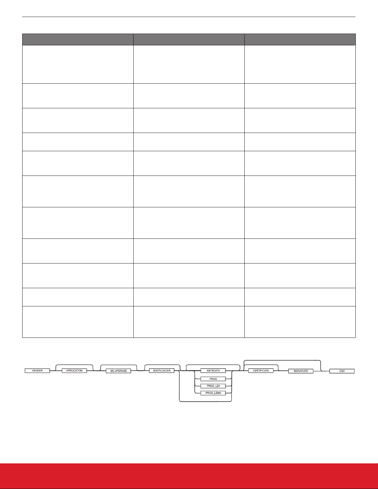
The allowed sequence of GBL tags in a GBL file is shown in the following figure.
Figure 2.1. GBL Tag Sequence
silabs.com | Building a more connected world. Rev. 1.6 | 10
Page 11
UG266: Silicon Labs Gecko Bootloader User’s Guide
Gecko Bootloader File Format
2.3 Encrypted Tag Descriptions
The encrypted GBL file format is similar to the unencrypted version. It introduces a number of new tags.
Tag Name ID Description
GBL Header Tag 0x03A617EB The GBL header is the same as for a plain-
text GBL file, but the flag indicating that the
GBL file is encrypted must be set.
GBL Encryption Init Header 0xFA0606FA This contains information about the image
encryption such as the Nonce and the
amount of encrypted data.
GBL Encrypted Program Data 0xF90707F9 This contains an encrypted payload con-
taining a plaintext GBL tag, one of Application Info, Bootoader, Metadata or Program
Data. The data is encrypted using AESCTR-128.
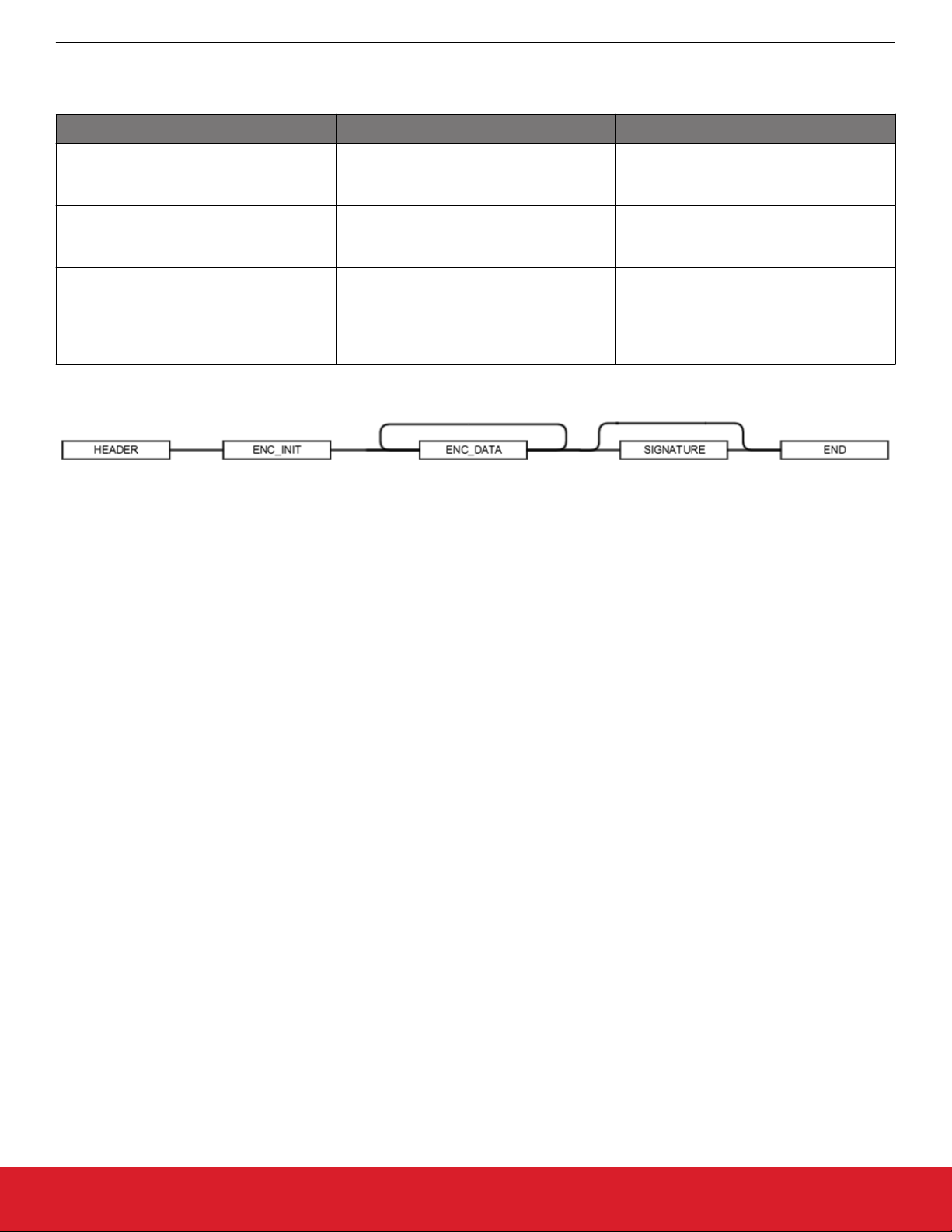
The allowed sequence of GBL tags in an encrypted GBL file is shown in the following figure.
Figure 2.2. Encrypted GBL Tag Sequence
silabs.com | Building a more connected world. Rev. 1.6 | 11
Page 12
UG266: Silicon Labs Gecko Bootloader User’s Guide
Gecko Bootloader Operation - Application Upgrade
3. Gecko Bootloader Operation - Application Upgrade
This section summarizes Gecko Bootloader operation for updating application firmware, first if the Gecko Bootloader is configured in
standalone mode and then if it is configured in application mode. Section 4. Gecko Bootloader Operation - Bootloader Upgrade provides the same information for updating the bootloader firmware.
The figures that illustrate Gecko Bootloader operation in this section do not provide information about the bootloader memory layouts
for different devices. For more details refer to the section "Memory Space for Bootloading" in UG103.6: Bootloader Fundamentals.
3.1 Standalone Bootloader Operation
Standalone bootloader operation is illustrated in the following figure:
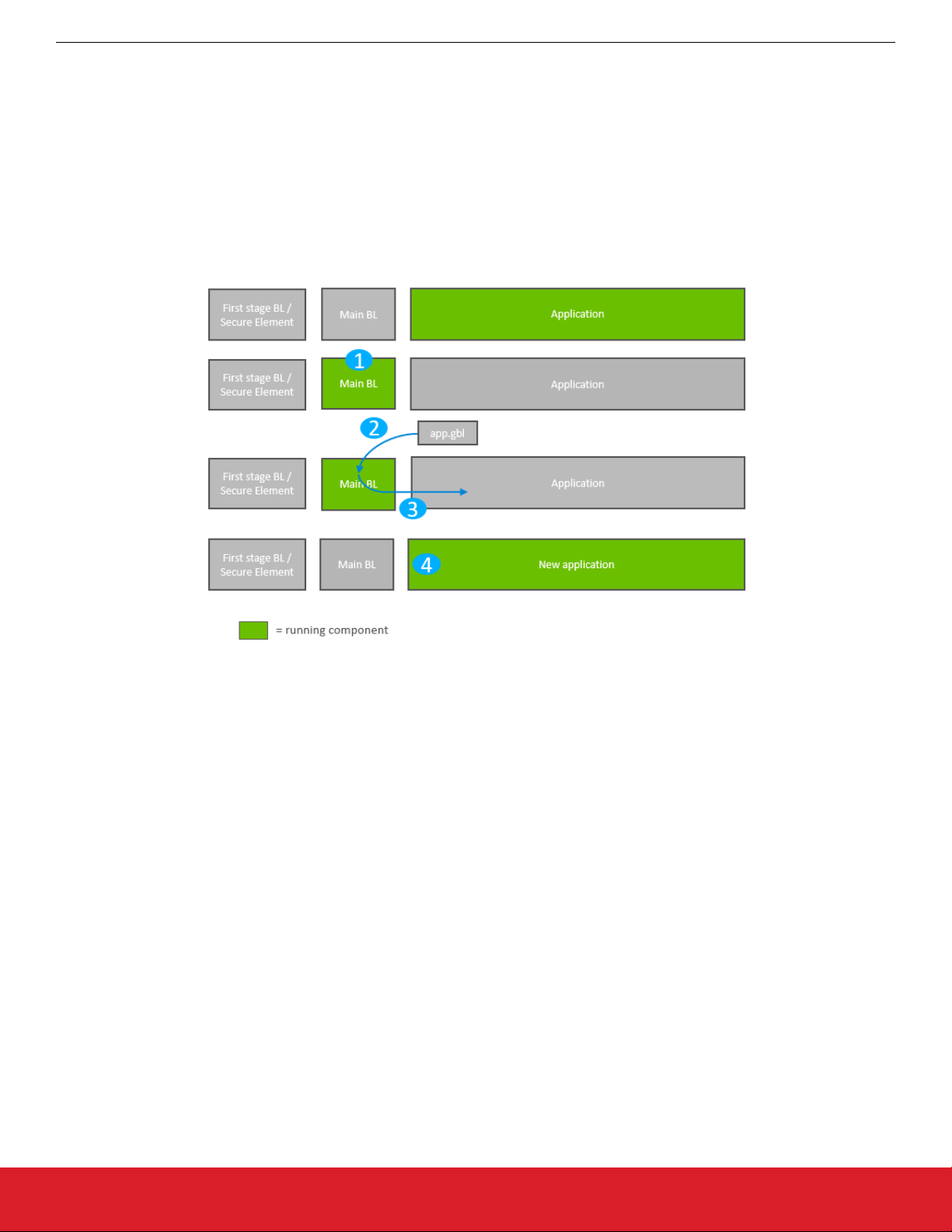
Figure 3.1. Standalone Bootloader Operation
1. The device reboots into the bootloader.
2. A GBL file containing an application image is transmitted from the host to the device. If image encryption is enabled in the main
stage bootloader and the image is encrypted, decryption is performed during the process of receiving and parsing the GBL file.
3. The bootloader applies the application upgrade from the GBL upgrade file on-the-fly. If image authentication is enabled in the main
stage bootloader and the GBL file contains a signature, the authenticity of the image is verified before completing the process.
4. The device boots into the application. Application upgrade is complete.
3.1.1 Rebooting Into the Bootloader
The Gecko Bootloader supports multiple mechanisms for triggering the bootloader. If the GPIO Activation plugin is enabled, the host
device can keep this pin low/high (depending on configuration) through reset to make the device enter the bootloader. The bootloader
can also be entered through software. The bootloader_rebootAndInstall API first signals to the bootloader that it should enter firmware upgrade mode by writing a command to the shared memory location at the bottom of SRAM, and then performs a software reset.
If the bootloader finds the correct command in shared memory upon boot, it will enter firmware upgrade mode instead of booting the
existing application.
3.1.2 Downloading and Applying a GBL Upgrade File
When the bootloader enters firmware upgrade mode, it enters a receive loop waiting for data from the host device. The specifics of the
receive loop depend on the protocol. Received packets are passed to the image parser, a state machine that parses the data and returns a callback containing any data that should be acted upon. The bootloader core implements this callback, and flashes the data to
internal flash at the address specified. If GBL file authentication or encryption is enabled, the image parser will enforce this, and abort
the image upgrade.
The bootloader prevents a newly uploaded image from being bootable by holding back parts of the application vector table until the
GBL file CRC and GBL signature (if required) have been verified.
silabs.com | Building a more connected world. Rev. 1.6 | 12
Page 13

UG266: Silicon Labs Gecko Bootloader User’s Guide
Gecko Bootloader Operation - Application Upgrade
3.1.3 Booting Into the Application
When an application upgrade is completed, the bootloader triggers a reboot with a message in shared memory at the bottom of SRAM
signaling that an application upgrade has been successfully completed. The application can use this reset information to learn that an
application upgrade was just performed.
Before jumping to the main application, the bootloader verifies that the application is ready to run. This includes verifying that the Program Counter of the application is valid, and, optionally if Secure Boot is enabled, that the application passes signature verification.
3.1.4 Error handling
If the application upgrade is interrupted at any time, the device will be without a working application. The bootloader then resets the
device, and re-enters firmware upgrade mode. The host device can easily restart the application upgrade process, to try loading the
upgrade image again.
silabs.com | Building a more connected world. Rev. 1.6 | 13
Page 14
UG266: Silicon Labs Gecko Bootloader User’s Guide
Gecko Bootloader Operation - Application Upgrade
3.2 Application Bootloader Operation
The following figure illustrates the application bootloader operation both for a single image/single storage slot, and multiple images/
multiple storage slots.
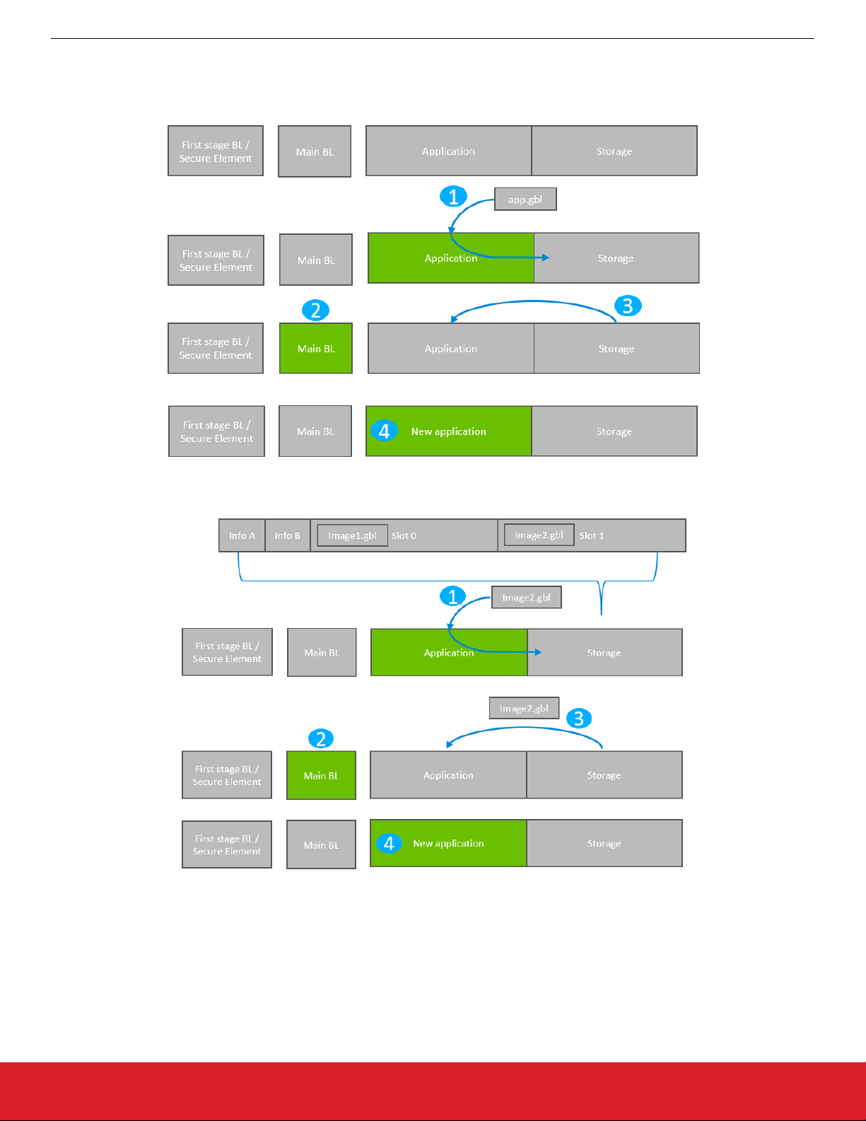
Figure 3.2. Application Bootloader Operation: Single Storage Slot
Figure 3.3. Application Bootloader Operation: Multiple Storage Slots
1. A GBL file is downloaded onto the storage medium of the device (internal flash or external dataflash), as described below, and the
presence of an upgrade image is indicated.
2. The device reboots into the bootloader, and the bootloader enters firmware upgrade mode.
3. The bootloader applies the application upgrade from the GBL upgrade file.
4. The device boots into the application. Application upgrade is complete.
silabs.com | Building a more connected world. Rev. 1.6 | 14
Page 15

UG266: Silicon Labs Gecko Bootloader User’s Guide
Gecko Bootloader Operation - Application Upgrade
3.2.1 Downloading and Storing a GBL Upgrade Image File
To prepare for receiving an upgrade image, the application finds an available storage slot, or erases an existing one using
bootloader_eraseStorage. If the bootloader only supports a single storage slot, a value of 0 should be used for the slot ID.
The application then receives a GBL file using an applicable protocol, such as Ethernet, USB, Zigbee, OpenThread or Bluetooth, and
stores it in the slot by calling bootloader_writeStorage.
When download is complete, the application can optionally verify the integrity of the GBL file by calling bootloader_verifyImage. This
is also done by the bootloader before applying the image, but can be done from the application in order to avoid rebooting into the
bootloader if the received image was corrupt.
If multiple storage slots are supported, the application should write a bootload list by calling bootloader_setImageToBootload. The list
is written to the two bootload info pages as shown in the second figure in section 3.2 Application Bootloader Operation. The bootload
list is a prioritized list of slots indicating the order the bootloader should use when attempting to perform a firmware upgrade. The bootloader attempts to verify the images in these storage slots in sequence, and applies the first image to pass verification. If only a single
storage slot is supported, the bootloader treats the entire download space as a single storage slot.
3.2.2 Rebooting and Applying a GBL Upgrade File
The bootloader can be entered through software. The bootloader_rebootAndInstall API signals to the bootloader that it should enter firmware upgrade mode by writing a command to the shared memory location at the bottom of SRAM, and then performs a software
reset. If the bootloader finds the correct command in shared memory upon boot, it enters firmware upgrade mode instead of booting the
existing application.
The bootloader iterates over the list of storage slots marked for bootload and attempts to verify the image stored in each. Once it finds a
valid GBL upgrade file, firmware upgrade is attempted from this GBL file. If the upgrade fails, the bootloader moves to the next image in
the list. If no images pass verification, the bootloader reboots back into the existing application with a message in the shared memory
location in SRAM indicating that no good upgrade images were found.
3.2.3 Booting Into the Application
When an application upgrade is completed, the bootloader triggers a reboot with a message in shared memory at the bottom of SRAM
signaling that an application upgrade has been successfully completed. The application can use this reset information to learn that an
application upgrade was just performed.
Before jumping to the main application, the bootloader verifies that the application is ready to run. This includes verifying that the Program Counter of the application is valid and optionally, if Secure Boot is enabled, that the application passes signature verification.
silabs.com | Building a more connected world. Rev. 1.6 | 15
Page 16
UG266: Silicon Labs Gecko Bootloader User’s Guide
Gecko Bootloader Operation - Bootloader Upgrade
4. Gecko Bootloader Operation - Bootloader Upgrade
Bootloader upgrade functionality is provided by the first stage bootloader on Series 1 devices, or the Secure Element on Series 2 devices. The Secure Element itself is also upgradable. More details can be found in section 5. Gecko Bootloader Operation - Secure Ele-
ment Upgrade. On Series 1 devices, the first stage bootloader is not upgradable.
Requirements for upgrading the main bootloader vary depending on the bootloader configuration:
• Application bootloader with storage: Upgrading the main bootloader requires a single GBL file containing both bootloader and application upgrade images.
• Standalone bootloader with communication interface: Upgrading the bootloader requires two GBL files, one with only the bootloader
upgrade image, and one with only the application upgrade image.
Security of the bootloader upgrade process is provided by signing the GBL file, as described in section 9.3.3 Creating a Signed and
Encrypted GBL Upgrade Image File From an Application.
The figures that illustrate Gecko Bootloader operation in this section do not provide information about the bootloader memory layouts
for different devices. For more details refer to the Memory Space For Bootloading section in UG103.6: Bootloader Fundamentals. For
convenience, the figures do not distinguish between SE and VSE.
4.1 Bootloader Upgrade on Bootloaders With Communication Interface (Standalone Bootloaders)
The process is illustrated in the following figure:
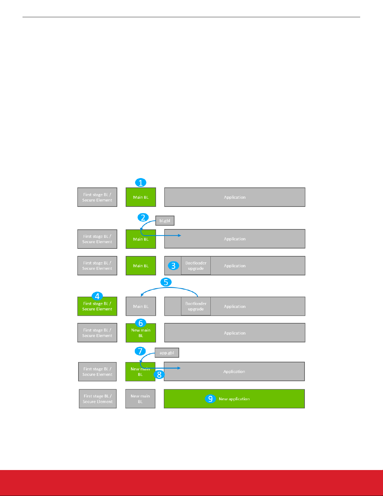
Figure 4.1. Standalone Bootloader: Bootloader Upgrade
silabs.com | Building a more connected world. Rev. 1.6 | 16
Page 17

UG266: Silicon Labs Gecko Bootloader User’s Guide
Gecko Bootloader Operation - Bootloader Upgrade
1. The device reboots into the bootloader.
2. A GBL file containing only a bootloader upgrade image is transmitted from the host to the device.
3. The contents of the GBL Bootloader tag are written to the bootloader upgrade location in internal flash, overwriting the existing
application.
4. The device reboots into the first stage bootloader / Secure Element.
5. The first stage bootloader / Secure Element replaces the main bootloader with the new version found in the bootloader upgrade
location.
6. The device boots into the new main bootloader.
7. A GBL file containing only an application image is transmitted from the host to the device.
8. The bootloader applies the application image from the GBL upgrade file on-the-fly.
9. The device boots into the application. Bootloader upgrade is complete.
A bootloader upgrade is started in the same way as an application upgrade.
4.1.1 Downloading and Applying a Bootloader GBL Upgrade File
When the bootloader has entered the receive loop, a GBL upgrade file containing a bootloader upgrade is transmitted to the bootloader.
When a packet is received, it is passed to the image parser. The image parser parses the data, and returns bootloader upgrade data in
a callback. The bootloader core implements this callback, and flashes the data to internal flash at the bootloader upgrade location.
The bootloader prevents a newly uploaded bootloader upgrade image from being interpreted as valid by holding back parts of the bootloader upgrade vector table until the GBL file CRC and GBL signature (if required) have been verified.
When a complete bootloader upgrade image is received, the main bootloader signals the first stage bootloader / Secure Element that it
should enter firmware upgrade mode. On Series 1 devices, this is done by writing a command to the shared memory location at the
bottom of SRAM, and then performing a software reset. On Series 2 devices, Secure Element communication is used to signal that
bootloader upgrade is ready to be performed.
On Series 1 devices, the first stage bootloader verifies the CRC on the current main bootloader and verifies the CRC of the bootloader
upgrade present in the bootloader upgrade location in internal flash.
• If the CRC in the upgrade image location and the CRC in the current main bootloader are both valid, then the upgrade image will be
copied over the main bootloader if the version number of the upgrade is higher than the current main bootloader version.
• If the CRC in the upgrade image location is valid and the CRC in the current main bootloader location is not valid, the upgrade image will be copied over the main bootloader regardless of the version. This is because the version of the main bootloader cannot be
relied upon if the main bootloader image is corrupt.
• If the CRC in the upgrade location is not valid, the upgrade will not be applied.
On Series 2 devices, the authenticity of the main bootloader optionally can be verified before applying the bootloader upgrade. See
section 7.5 Setting a Version Number for more information about versioning bootloader images.
4.1.2 Upgrading Bootloaders Without Secure Boot to Bootloaders With Secure Boot
A bootloader without the secure boot feature can be upgraded to a bootloader with the secure boot feature, using the following procedure:
1. Prepare a Gecko Bootloader image with secure boot enabled. The version of the bootloader needs to be higher than the bootloader on the device.
• Turn on secure boot in AppBuilder by going to the Core plugin and selecting the Enable secure boot option.
• (Optional) In the Core plugin, select the Require signed firmware upgrade files option. This means that the Gecko Bootloader
will only accept signed GBL files.
2. Generate a public/private Signing Key pair. See section 9.3.1 Generating Keys for more information on creating a Signing Key pair.
3. Write the public key generated from the previous step to the device. The public key is stored as a manufacturing token in the device by default. This key can be written by application code running on the device as long as the Lock Bits page is configured to
allow flash writes. If the Lock Bits page is locked, it can only be erased by the debugger. Therefore, signing/decryption keys residing in the Lock Bits page cannot be erased from firmware. This means that, for devices in the field, those areas in flash cannot be
replaced with new ones. However, the Gecko Bootloader prepared from step 1 can be modified to look for the decryption and signature keys in a different location. Key locations are defined in the bootloader project file btl_security_tokens.c.
4. Create a GBL file using the Gecko Bootloader image. The GBL file needs to be signed/unsigned depending on the current configuration of the Gecko Bootloader running on the device. For more details on creating a GBL file see section 9.3.3 Creating a Signed
and Encrypted GBL Upgrade Image File From an Application.
5. Upload the GBL file. For more details on the upgrade process refer to section 4.1 Bootloader Upgrade on Bootloaders With Com-
munication Interface (Standalone Bootloaders).
silabs.com | Building a more connected world. Rev. 1.6 | 17
Page 18

UG266: Silicon Labs Gecko Bootloader User’s Guide
Gecko Bootloader Operation - Bootloader Upgrade
4.1.3 Enabling Secure Boot RTSL on Series 2 Devices
Secure Boot RTSL (Root of Trust and Secure Loader) can be enabled using the following procedure:
1. Prepare a Gecko Bootloader image with secure boot enabled. The version of the Gecko Bootloader needs to be higher than the
Gecko Bootloader on the device.
• Turn on secure boot in AppBuilder by going to the Core plugin and selecting the Enable secure boot option.
• For EFR32xG21, on the Core plugin, disable the Allow use of public key from manufacturing token storage option. This
means that the Gecko Bootloader will never make use of the public key stored in the last page of the main flash
• (Optional) On the Core plugin, select the Require signed firmware upgrade files option from the Core plugin. The means that
the Gecko Bootloader will only accept signed GBL files.
2. Generate a public/private Signing Key pair. See section 9.3.1 Generating Keys for more information on creating a Signing Key pair.
3. Prepare an application that installs the public key generated from step 2 to the Secure Element One-time Programmable memory.
Installing a key in the VSE requires a reset routine. Make sure that the application does not end up in the reset loop. Create an
unsigned GBL file from this application and upload it. For more information on installing public keys, see section 9.3.3 Creating a
Signed and Encrypted GBL Upgrade Image File From an Application.
4. Sign the Gecko Bootloader image generated from step 1 using the private key generated in step 2. See section 9.3.2 Signing an
Application Image for Secure Boot for more information on signing binaries.
5. Make a custom application that turns on secure boot on the Secure Element and sign this application binary with the private key
generated from step 2. For more details on how to turn on secure boot on the Secure Element, see AN1218: Series 2 Secure Boot
with RTSL.
6. Create a GBL file using the Gecko Bootloader image from step 4.
7. Create a GBL file using the application from step 5. The GBL file need to be signed if the Core plugin option Require signed firm-
ware upgrade files was selected in step 1.
8. Upload the GBL file containing the Gecko Bootloader image.
9. Upload the GBL file containing the application.
4.1.4 Downloading and Applying an Application GBL Upgrade File
Once the bootloader upgrade is completed, the existing application is rendered invalid, since the bootloader upgrade location overlaps
with the application. A GBL upgrade file containing an application upgrade is transmitted to the bootloader. The application upgrade
process follows that in section 3.1 Standalone Bootloader Operation.
silabs.com | Building a more connected world. Rev. 1.6 | 18
Page 19
4.2 Bootloader Upgrade on Application Bootloaders With Storage
The process is illustrated in the following figure.
UG266: Silicon Labs Gecko Bootloader User’s Guide
Gecko Bootloader Operation - Bootloader Upgrade
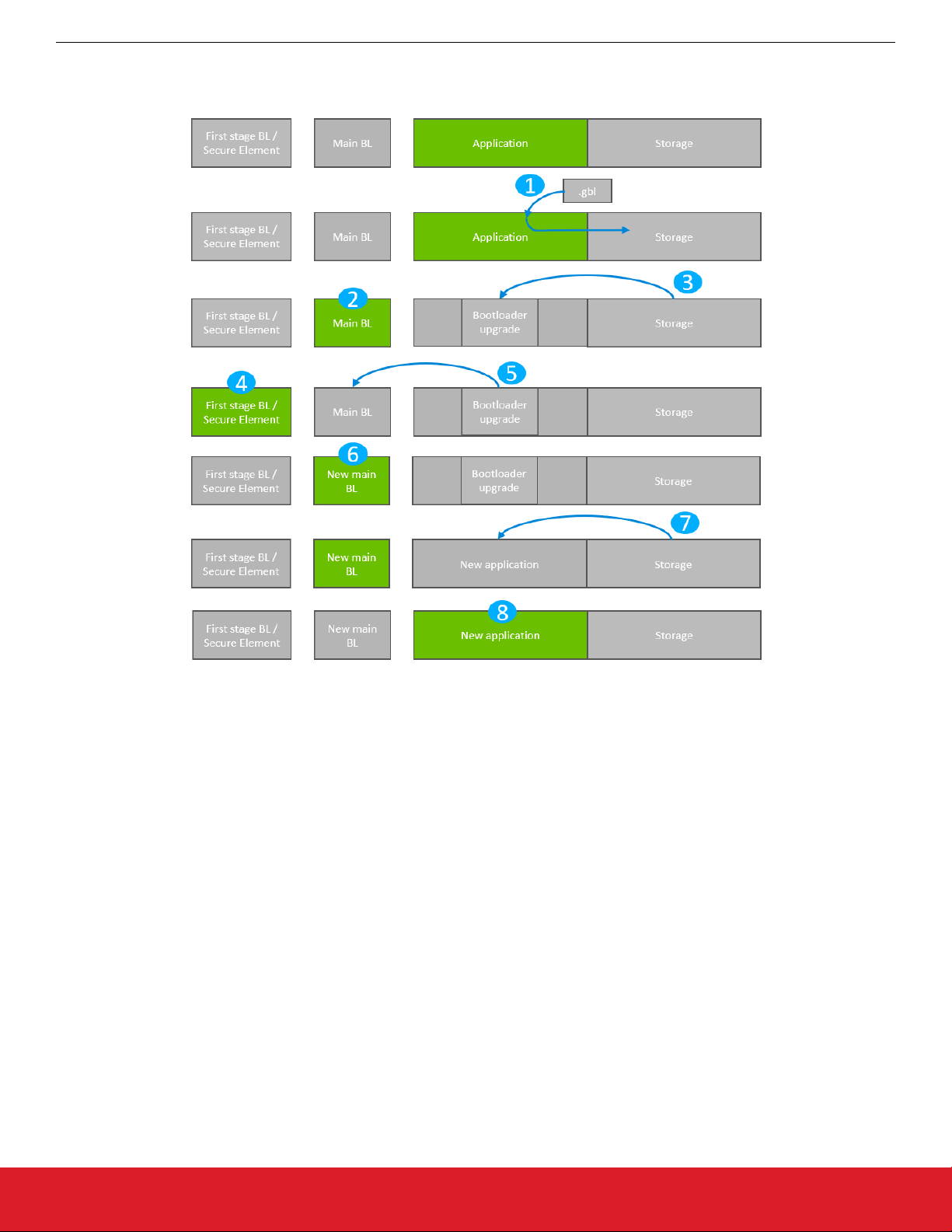
Figure 4.2. Application Bootloader: Bootloader Upgrade
1. A single GBL file containing both a bootloader upgrade image and an application image is downloaded onto the storage medium of
the device (internal flash or external SPI flash).
2. The device reboots into the bootloader.
3. The main bootloader copies its upgrade image into internal flash at the bootloader upgrade location, overwriting the existing application.
4. The device reboots into the first stage bootloader / Secure Element.
5. The first stage bootloader / Secure Element replaces the main bootloader with the new version.
6. The device boots into the new main bootloader.
7. The bootloader applies the application image from the GBL upgrade file.
8. The device boots into the application. Bootloader upgrade is complete.
A bootloader upgrade is started in the same way as an Application Upgrade. A single GBL file containing both a bootloader and an
application upgrade is written to storage by the application, and the bootloader is entered.
The bootloader iterates over the list of storage slots marked for bootload, and attempts to verify the GBL file stored within. Verification
returns information about whether the GBL file contains an application, or both a bootloader and an application. The image parser parses the file. If the GBL file contains a bootloader, the bootloader upgrade data is returned in a callback. The bootloader core implements this callback, and flashes the data to internal flash at the bootloader upgrade location.
The bootloader prevents a newly uploaded bootloader upgrade image from being interpreted as valid by holding back parts of the bootloader upgrade vector table until the GBL file CRC and GBL signature (if required) have been verified.
On Series 1 devices, the main bootloader signals the first stage bootloader that it should enter firmware upgrade mode by writing a
command to the shared memory location at the bottom of SRAM, and then performing a software reset. On Series 2 devices, Secure
Element communication interface is used to signal the Secure Element that a bootloader upgrade is ready to be performed.
silabs.com | Building a more connected world. Rev. 1.6 | 19
Page 20

UG266: Silicon Labs Gecko Bootloader User’s Guide
Gecko Bootloader Operation - Bootloader Upgrade
On Series 1 devices, the first stage bootloader verifies the CRC of the bootloader upgrade present in the bootloader upgrade location in
internal flash, and copies the bootloader upgrade over the main bootloader if the version number of the upgrade is higher than the version number of the existing main bootloader. On Series 2 devices, the authenticity of the main bootloader optionally can be verified
before applying the bootloader upgrade. See section 7.5 Setting a Version Number for more information about versioning bootloader
images.
The new main bootloader is entered, and the images in the list of storage slots marked for bootload are verified. When the image parser
parses the slot containing the GBL file with the bootloader + application upgrade, the version number of the bootloader upgrade is
equal to the running main bootloader version, so another bootloader upgrade will not be performed. Instead, the application upgrade
data are returned in a callback. Bootloading of the new application proceeds as described in section 3.2 Application Bootloader Opera-
tion.
4.2.1 Storage Space Size Configuration
The storage space size must be configured to have enough space to store the upgrade images. Depending on the configuration, the
bootloader size can vary. The size requirements of the bootloader can be found in section 7.7 Size Requirements for Different Boot-
loader Configurations for Series 1 Devices.
4.2.2 Upgrading Bootloaders without Secure Boot to Bootloaders with Secure Boot
A bootloader without the secure boot feature can be upgraded to a bootloader with the secure boot feature. The procedure is as follows:
1. Prepare a Gecko Bootloader image with secure boot enabled. The version of the bootloader needs to be higher than the bootloader on the device.
• Turn on secure boot from the Core plugin in AppBuilder by selecting the Enable secure boot option..
2. Generate a public/private Signing Key pair. See section 9.3.1 Generating Keys for more information on creating a Signing Key pair.
3. Write the public key generated from the previous step to the device. The public key is stored as a manufacturing token in the device by default. This key can be written by application code running on the device as long as the Lock Bits page is configured to
allow flash writes. If the Lock Bits page is locked, it can only be erased by the debugger. Therefore, signing/decryption keys residing in the Lock Bits page cannot be erased from firmware. This means that, for devices in the field, those areas in flash cannot be
replaced with new ones. However, the Gecko Bootloader prepared from step 1 can be modified to look for the decryption and signature keys in a different location. Key locations are defined in the bootloader project file btl_security_tokens.c.
4. Prepare a signed application image using the private key generated in step 2. See section 9.3.2 Signing an Application Image for
Secure Boot for more information on signing an application.
5. Create a GBL file using the Gecko Bootloader image and the signed application image. The GBL file needs to be signed/unsigned
depending on the configuration of the Gecko Bootloader running on the device. For more details on creating a GBL file see section
9.3.3 Creating a Signed and Encrypted GBL Upgrade Image File From an Application.
6. Upload the GBL file. For more details on the upgrade process refer to section 4.2 Bootloader Upgrade on Application Bootloaders
With Storage.
silabs.com | Building a more connected world. Rev. 1.6 | 20
Page 21

UG266: Silicon Labs Gecko Bootloader User’s Guide
Gecko Bootloader Operation - Bootloader Upgrade
4.2.3 Enabling Secure Boot RTSL on Series 2 Devices
Secure Boot RTSL can be enabled by using the following procedure:
1. Prepare a Gecko Bootloader image with secure boot enabled. The version of the Gecko Bootloader needs to be higher than the
Gecko Bootloader on the device.
• Turn on secure boot from the Core plugin in AppBuilder by selecting the Enable secure boot option..
• For EFR32xG21, on the Core plugin, disable the Allow use of public key from manufacturing token storage option. This
means that the Gecko Bootloader will never make use of the public key stored in the last page of the main flash.
• (Optional) On the Core plugin, select the Require signed firmware upgrade files option from the Core plugin. The means that
the Gecko Bootloader will only accept signed GBL files.
2. Generate a public/private Signing Key pair. See section 9.3.1 Generating Keys for more information on creating a Signing Key pair.
3. Prepare an application that installs the public key generated from step 2 to the Secure Element One-time Programmable memory.
Installing a key in VSE requires a reset routine. Make sure that the application does not end up in the reset loop. Create an unsigned GBL file from this application and upload it.. For more information on installing public keys, see AN1218: Series 2 Secure
Boot with RTSL. For more details on creating a GBL file see section 9.3.3 Creating a Signed and Encrypted GBL Upgrade Image
File From an Application.
4. Sign the Gecko Bootloader image generated from step 1 using the private key generated in step 2. See section 9.3.2 Signing an
Application Image for Secure Boot for more information on signing binaries.
5. Make a custom application that turns on secure boot on the Secure Element and sign this application binary with the private key
generated from step 2. For more details on how to turn on secure boot on the Secure Element, see AN1218: Series 2 Secure Boot
with RTSL.
6. Create a GBL file using the Gecko Bootloader image from step 4 and the application from step 5. The GBL file must be signed if
the Core plugin option Require signed firmware upgrade files was selected in step 1. For more details on creating a GBL file see
section 9.3.3 Creating a Signed and Encrypted GBL Upgrade Image File From an Application.
7. Upload the GBL file containing the Gecko Bootloader image and the application.
silabs.com | Building a more connected world. Rev. 1.6 | 21
Page 22
UG266: Silicon Labs Gecko Bootloader User’s Guide
Gecko Bootloader Operation - Secure Element Upgrade
5. Gecko Bootloader Operation - Secure Element Upgrade
The Secure Element is upgradable and requirements for upgrading the Secure Element vary depending on the bootloader configuration:
• Application bootloader with storage: Upgrading the Secure Element requires a single GBL file containing both Secure Element
and application upgrade images.
• Standalone bootloader with communication interface: Upgrading the Secure Element requires two GBL files, one with only the
Secure Element upgrade image, and one with only the application upgrade image and optionally a third image containing only the
Main bootloader upgrade.
A bootloader upgrade can also be included in the same GBL file in application mode, or as a third GBL file in standalone mode. The
figures that illustrate Gecko Bootloader operation in this section do not provide information about the bootloader memory layouts for
different devices. For more details refer to the section Memory Space for Bootloading in UG103.6: BootloaderFundamentals.
Signed and encrypted Secure Element upgrade images are provided by Silicon Labs through Simplicity Studio. Upgrade images with
the same or lower version number than the running Secure Element will be ignored.
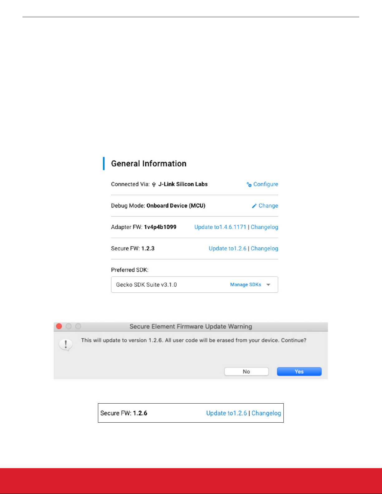
To download Secure Element firmware images, connect a Series 2 device and select a preferred SDK. The Secure Firmware Update
to x.x.x link appears in the Launcher Perspective, as shown in the following figure.
Update to x.x.x next to Secure FW: x.x.x. A warning dialog box appears. Click [Yes]to continue.
Click
The Launcher Perspective is then updated so that the current Secure Fimware version and link version are the same.
The Secure Element firmware images can be found in the util/se_release/public directory under the Gecko SDK. Simplicity Studio displays the SE firmware version available in the Gecko SDK selected.
silabs.com | Building a more connected world. Rev. 1.6 | 22
Page 23
UG266: Silicon Labs Gecko Bootloader User’s Guide
Gecko Bootloader Operation - Secure Element Upgrade
5.1 Secure Element Upgrade on Bootloaders with Communication Interface (Standalone Bootloaders)
The process is illustrated in the following figure.
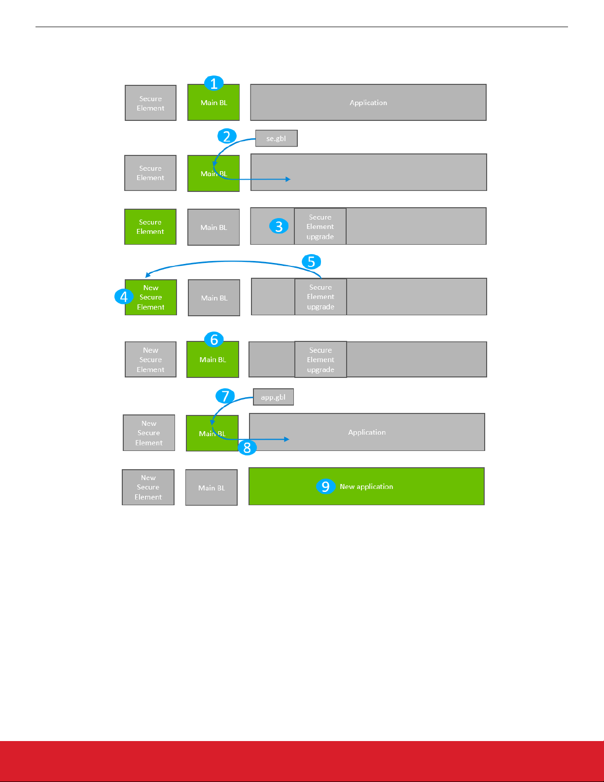
Figure 5.1. Standalone Bootloader: Secure Element Bootloader Upgrade
1. The device reboots into the bootloader.
2. A GBL file containing only a Secure Element upgrade image is transmitted from the host to the device.
3. The contents of the GBL Secure Element tag are written to the pre-configured upgrade location in internal flash, overwriting the
existing application.
4. The device reboots into the Secure Element.
5. The Secure Element is replaced by the new version found in the pre-configured upgrade location.
6. The device boots into the main bootloader.
7. A GBL file containing only an application image is transmitted from the host to the device.
8. The bootloader applies the application image from the GBL upgrade on the fly.
9. The device boots into the application. Secure Element upgrade is complete.
silabs.com | Building a more connected world. Rev. 1.6 | 23
Page 24

UG266: Silicon Labs Gecko Bootloader User’s Guide
Gecko Bootloader Operation - Secure Element Upgrade
5.1.1 Downloading and Applying a Secure Element GBL Upgrade File
When the bootloader has entered the receive loop, a GBL upgrade file containing a Secure Element upgrade is transmitted to the bootloader. When a packet is received, it is passed to the image parser. The image parser parses the data, and returns Secure Element
upgrade data in a callback. The bootloader core implements this callback, and flashes the data to internal flash at the pre-configured
bootloader upgrade location.
When a complete Secure Element upgrade image is received, the main bootloader signals the Secure Element that it should enter firmware upgrade mode. This is done by the Secure Element communication interface that is used to signal that bootloader upgrade is
ready to be performed.
5.1.2 Downloading and Applying an Application GBL Upgrade File
Once the Secure Element upgrade is completed, the existing application is rendered invalid if the Secure Element upgrade location
overlaps with the application. A GBL upgrade file containing an application upgrade is transmitted to the bootloader. The application
upgrade process follows that in section 3.1 Standalone Bootloader Operation.
silabs.com | Building a more connected world. Rev. 1.6 | 24
Page 25
Gecko Bootloader Operation - Secure Element Upgrade
5.2 Secure Element Upgrade on Application Bootloaders with Storage
The process is illustrated in the following figure.
UG266: Silicon Labs Gecko Bootloader User’s Guide
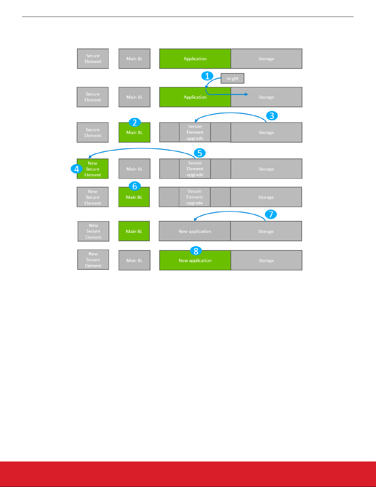
Figure 5.2. Application Bootloader: Secure Element Upgrade
1. A single GBL file containing both a Secure Element upgrade image and an application image is downloaded onto the storage medium of the device (internal flash or external SPI flash).
2. The device reboots into the bootloader.
3. The main bootloader copies its upgrade image into internal flash at the pre-configured upgrade location.
4. The device reboots into the Secure Element.
5. The Secure Element is replaced by the new version found in the pre-configured upgrade location.
6. The device boots into the main bootloader.
7. The bootloader applies the application image from the GBL upgrade file.
8. The device boots into the application. Secure Element upgrade is complete
5.2.1 Storage Space Size Configuration
The storage space size must be configured to have enough space to store the upgrade images. The SE upgrade image requires about
42 kB and the VSE upgrade image requires 24 kB. Depending on the configuration, the bootloader size can vary. The size requirements of the bootloader can be found in section 7.7 Size Requirements for Different Bootloader Configurations for Series 1 Devices.
The bootloader size for EFR32xG21 devices can be up to 16 kB and for EFR32xG22 devices the bootloader size can be up to 24 kB.
For more details refer to the section "Memory Space for Bootloading" in UG103.6: Bootloader Fundamentals.
silabs.com | Building a more connected world. Rev. 1.6 | 25
Page 26

UG266: Silicon Labs Gecko Bootloader User’s Guide
Getting Started with the Gecko Bootloader
6. Getting Started with the Gecko Bootloader
This section describes how to build a Gecko Bootloader from one of the provided examples. Simplicity Studio 5, used with Gecko SDK
Suite (GSDK) v3.x, differs from Simplicity Studio 4, used with GSDK v2.x, in how sample applications are selected and projects are
created. Refer to the documentation provided with your SDK for details. These instructions assume that you have installed Simplicity
Studio 5, the protocol SDK, and associated utilities as described in the SDK’s quick start guide, and that you are familiar with generating, compiling, and flashing an example application in th relevant version.
• QSG106: EmberZNet PRO Quick-Start Guide
• QSG139: Bluetooth® SDK v2.x Quick-Start Guide
• QSG169: Bluetooth® SDK v3.x Quick-Start Guide
• QSG138: Proprietary Flex SDK v2.x Quick-Start Guide
• QSG168: Proprietary Flex SDK v3.x Quick-Start Guide
• QSG170: Silicon Labs OpenThread SDK Quick-Start Guide
1. Create a project based on the Gecko Bootloader example of your choice.
2. On the General tab, optionally enter a description.
silabs.com | Building a more connected world. Rev. 1.6 | 26
Page 27
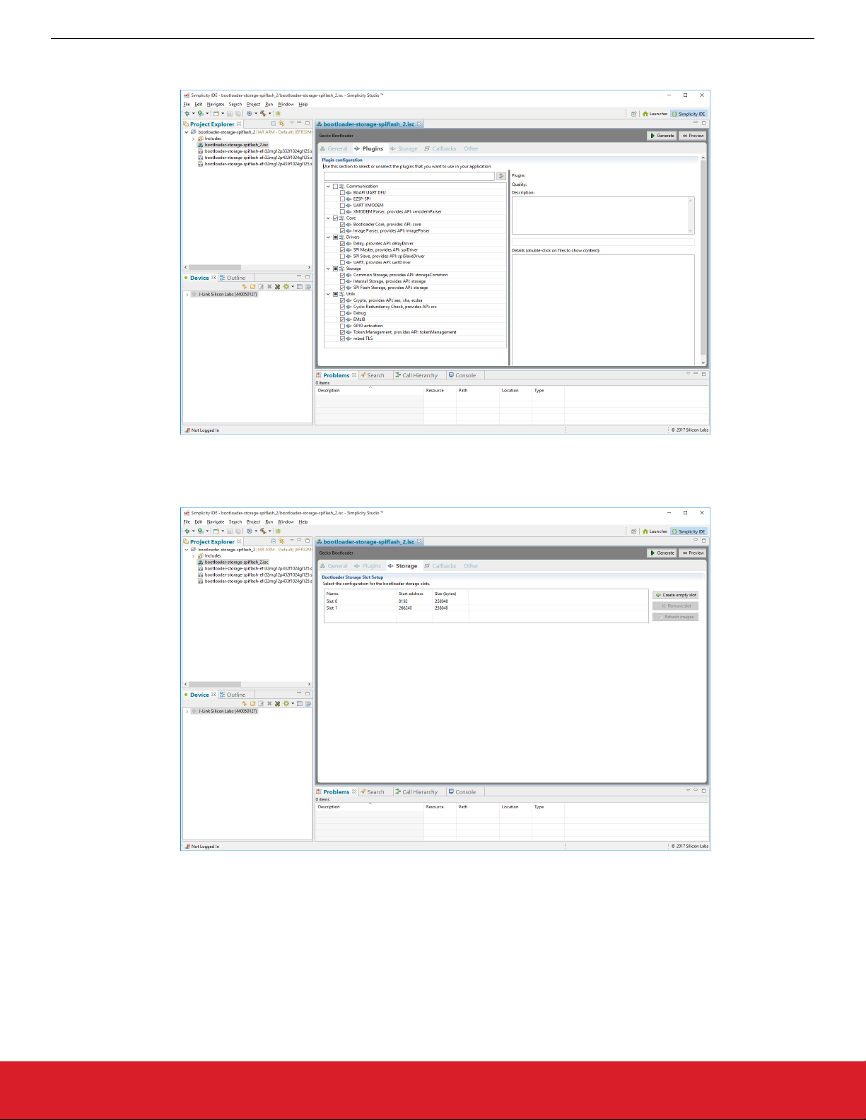
3. The Plugins tab shows the configurations selected for the relevant example.
UG266: Silicon Labs Gecko Bootloader User’s Guide
Getting Started with the Gecko Bootloader
4. The Storage tab allows you to configure storage slots to be used if a storage plugin is enabled. The default configuration matches
the target part and bootloader type.
5. Click [Generate].
6. In the Generation Successful dialog, click [OK].
7. Click the Build (hammer) icon.
On Series 1 devices, three bootloader images are generated into the build directory: a main bootloader, a main bootloader with CRC32
checksum, and a combined first stage and main bootloader with CRC32 checksum. The main bootloader image is called <project-
name>.s37, the main bootloader with CRC32 checksum is called <projectname>-crc.s37, while the combined first stage image +
main bootloader image with a CRC32 checksum is called <projectname>-combined.s37. The first time a device is programmed,
whether during development or manufacturing, the combined image needs to be programmed. For subsequent programming, when a
first stage bootloader is already present on the device, it is okay to download an image containing just the main bootloader. In this case,
the main bootloader with CRC32 should be used.
silabs.com | Building a more connected world. Rev. 1.6 | 27
Page 28

UG266: Silicon Labs Gecko Bootloader User’s Guide
Getting Started with the Gecko Bootloader
The requirement is that any main bootloader image that is programmed via serial wire must contain the CRC32 in the image. Files
downloaded via serial wire are “s37” files. Most often, the <projectname>-combined.s37 file is the one downloaded during production
programming. However, it is possible to download only the main bootloader over serial wire, in which case <projectname>-crc.s37
should be used.
Any main bootloader that is upgraded via OTA or host method should already contain CRC32 because bootloader-initiated upgrades
use GBL files (not “s37” files) and Simplicity Commander will add the CRC32 when it constructs the GBL file. The input files to Simplicity Commander can (and should) use the non-CRC “s37” file.
On Series 2 devices, the combined image is not present, since the first stage bootloader does not exist. The image containing only a
main bootloader is the image that must be used to create a GBL file for bootloader upgrade.
silabs.com | Building a more connected world. Rev. 1.6 | 28
Page 29
UG266: Silicon Labs Gecko Bootloader User’s Guide
Configuring the Gecko Bootloader
7. Configuring the Gecko Bootloader
7.1 Configuring Storage
Gecko Bootloaders configured as application bootloaders must include an API to store and access image files. This API is based on the
concept of storage slots, where each slot has a predefined size and location in memory, and can be used to store a single upgrade
image. This is done by configuring the Storage plugins in the Bootloader application framework in Simplicity Studio.
When multiple storage slots are configured, a bootload list is used to indicate the order in which the bootloader should access slots to
find upgrade images. If multiple storage slots are supported, the application should write the bootload list by calling
bootloader_setImageToBootload before rebooting into the bootloader to initiate a firmware upgrade process. The bootloader at-
tempts to verify the images in these storage slots in sequence, and applies the first image to pass verification. If only a single storage
slot is supported, the bootloader uses this slot implicitly.
7.1.1 SPI Flash Storage Configuration
When configuring a Gecko Bootloader to obtain images from SPI flash, modify the following.
The base address of the storage area should be configured in the Common Storage plugin. This is the address at which the bootloader places the bootload list, if more than one storage slot is configured. In the default configuration, this address is set to 0. If only a
single storage slot is configured, the bootload list is not used, so configuring it may be omitted.
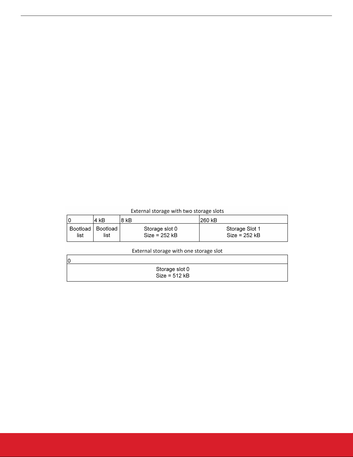
The location and size of the storage slots can be configured on the Storage tab in AppBuilder. The addresses input here are absolute addresses (they are not offsets from the base address). If more than a single slot is configured, space must be reserved between
the base address as configured in the Common Storage plugin and the first storage slot configured on the Storage tab. Enough space
to fit two copies of the bootload list must be reserved. These two copies need to reside on different flash pages, to provide redundancy
in case of power loss during writing. Two full flash pages therefore need to be reserved. In the default example application, a SPI flash
part with 4 kB flash sectors is used. This means that 8 kB must be reserved before the first storage slot. The following figure illustrates
how the storage area can be partitioned, where the numbers in the top row represent the starting addresses.
Figure 7.1. SPI Flash Storage Area Configuration
silabs.com | Building a more connected world. Rev. 1.6 | 29
Page 30

UG266: Silicon Labs Gecko Bootloader User’s Guide
Configuring the Gecko Bootloader
7.1.2 Internal Storage Configuration
When configuring a Gecko Bootloader to obtain images from intenal flash, modify the following.
The base address of the storage area should be configured in the Common Storage plugin. This is the address at which the bootloader will place the prioritized list of storage slots to attempt to bootload from, if more than one storage slot is configured. In the default
configuration, only a single storage slot is configured, so this value is set to 0, and isn’t used. If more than one storage slot is configured, this value needs to be configured too.
The location and size of the storage slots can be configured on the Storage tab in AppBuilder. The addresses input here are absolute addresses (they are not offsets from the base address). If more than a single slot is configured, enough space must be reserved
between the base address as configured in the Common Storage plugin and the first storage slot configured on the Storage tab.
Enough space to fit two copies of the bootload list must be reserved. These two copies need to reside on different flash pages, to provide redundancy in case of power loss during writing. Two full flash pages therefore need to be reserved. The following figure illustrates
how the storage area can be partitioned.
Figure 7.2. Internal Storage Area Configurations
Note: The storage area partitioning in the example for two storage slots above does not take any NVM system into account. If using an
NVM system like SimEE or PS Store, take care to place and size the storage area in such a way that bootloader storage does not
overlap with NVM.
silabs.com | Building a more connected world. Rev. 1.6 | 30
Page 31
UG266: Silicon Labs Gecko Bootloader User’s Guide
Configuring the Gecko Bootloader
7.2 Compressed Upgrade Images
The Gecko Bootloader optionally supports compressed GBL files. In a compressed GBL file, only the application upgrade data is compressed, any metadata and bootloader upgrade data (if present) stay uncompressed. This means that a compressed GBL file is identical to a normal (uncompressed) GBL file, except that the GBL Programming Tag containing the application upgrade image (as described in UG103.6: Bootloader Fundamentals) has been replaced by a GBL LZ4 Compressed Programming Tag or GBL LZMA Compressed Programming Tag. Signature and encryption operations on a compressed GBL work identically to on an uncompressed GBL.
To be able to use compressed upgrade images, a decompressor for the relevant compression algorithm must be added to the Gecko
bootloader. The following table shows which compression algorithms are supported by the Gecko Bootloader, and which AppBuilder
plugin should be added to enable the feature. The table also shows how much space the decompressor takes up in the bootloader, and
how big of a size reduction to expect for the compressed application upgrade image. Be aware of the bootloader size requirement. The
bootloader space might be too small to fit the decompressors, depending on the device and enabled plugins.
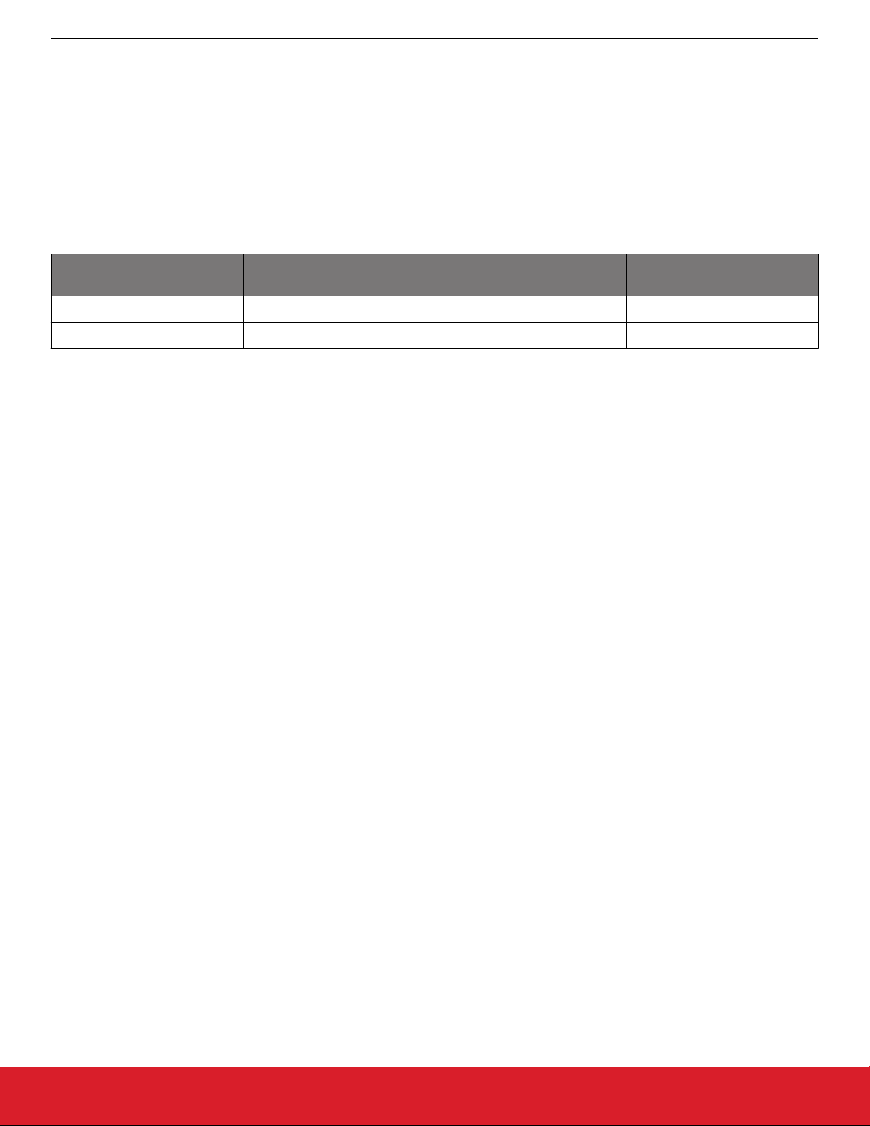
Compression Algorithm Plugin Bootloader Size Requirement Application Upgrade Size Re-
duction (typical)
LZ4 GBL Compression (LZ4) < 1 kB ~ 10%
LZMA GBL Compression (LZMA) ~5 kB flash, 18 kB RAM ~ 30%
It is important to note that the compressed GBL file stays compressed while being transferred to the device, and while it is stored in the
upgrade area. It is decompressed by the bootloader when the upgrade is applied. This means that the running application in main flash
will be identical to one that was installed using an uncompressed (normal) GBL file.
Compressed GBL files can only be decompressed by the bootloader when running standalone, not through the Application Interface.
This means that upgrade image verification performed by the application prior to reboot will not attempt to decompress the application
upgrade, it will only verify the signature of the compressed payload. After rebooting into the bootloader, it will decompress the image as
part of the upgrade process.
Note: The above means that Bluetooth in-place application upgrades cannot be compressed, as they are processed by the Bluetooth
Supervisor or AppLoader using functionality in the bootloader through the Application Interface. Supervisor/stack and AppLoader updates can be compressed, but the user application cannot.
7.2.1 LZMA Compression Settings
LZMA decompression is only supported for images compressed with certain compression settings. Simplicity Commander automatically
uses these settings when using the commander gbl create --compress lzma command.
• Probability model counters: lp + lc <= 2. Simplicity Commander uses lp=1, lc=1.
• Dictionary size no greater than 8 kB. Simplicity Commander uses 8 kB.
Together, these settings cause the decompressor to require 18 kB of RAM for decompression – 10 kB for the counters and 8 kB for the
dictionary.
The GBL LZMA Compressed Programming Tag contains a full LZMA file, containing the LZMA header, raw stream, and end mark. The
Gecko bootloader only supports decompressing payloads that contain the end mark as the last 8 bytes of the compressed stream.
7.3 Bootloader Example Configurations
The following sections describe the key configuration options for the example bootloader applications.
Note: Security features are disabled for all example configurations. In development, Silicon Labs strongly recommends enabling security features to prevent unauthorized parties from uploading untrusted program code. See the section 9.3 Using Application Image Secur-
ity Features to learn how to configure the security features of the Gecko Bootloader.
silabs.com | Building a more connected world. Rev. 1.6 | 31
Page 32

UG266: Silicon Labs Gecko Bootloader User’s Guide
Configuring the Gecko Bootloader
7.3.1 UART XMODEM Bootloader
Standalone bootloader for EFM32 and EFR32 devices running the EmberZNet PRO and Silicon Labs Connect protocol stacks, using
XMODEM-CRC over UART.
In this configuration, the XMODEM UART communication plugin, XMODEM parser plugin, and UART driver plugin are enabled. In order
for the example application to run on a custom board, the GPIO ports and pins used for UART need to be configured. This is done by
going to the Plugins tab of the AppBuilder project, and selecting the UART driver plugin. Here, Hardware Flow Control can be enabled
or disabled, and the baud rate and pinout can be configured.
The GPIO activation plugin is also enabled by default, allowing bootloader entry into firmware upgrade mode by activating a GPIO
through reset. This plugin can be disabled if this functionality is not desired, or the GPIO pin used for this can be configured under the
GPIO Activation plugin on the Plugins tab.
7.3.2 BGAPI UART DFU Bootloader
Standalone bootloader for the Bluetooth protocol stack, using the BGAPI protocol for UART DFU. This bootloader should be used for all
NCP-mode Bluetooth applications.
In this configuration, the BGAPI UART DFU communication plugin and UART driver plugin are enabled. In order for the example application to run on a custom board, the GPIO ports and pins used for UART need to be configured. This is done by going to the Plugins
tab of the AppBuilder project, and selecting the UART driver plugin. Here, Hardware Flow Control can be enabled or disabled, and the
baud rate and pinout can be configured.
The GPIO activation plugin is also enabled by default, allowing bootloader entry by activating a GPIO through reset. This plugin can be
disabled if this functionality is not desired, or the GPIO pin used for this can be configured under the GPIO Activation plugin on the
Plugins tab.
7.3.3 EZSP SPI Bootloader
Standalone bootloader for EmberZNet PRO and Silicon Labs Connect protocol stacks using EZSP for SPI.
In this configuration, the EZSP SPI communication plugin, XMODEM parser plugin, and SPI slave driver plugin are enabled. In order for
the example application to run on a custom board, the GPIO ports and pins used for SPI and EZSP signaling need to be configured.
This is done by going to the Plugins tab of the AppBuilder project, and selecting the SPI slave and EZSP SPI plugins respectively.
The EZSP GPIO activation plugin is also enabled by default, allowing bootloader entry into firmware upgrade mode by activating a
GPIO through reset. This plugin can be disabled if this functionality is not desired, or the GPIO pin used for this can be configured
under the EZSP GPIO Activation plugin on the Plugins tab.
7.3.4 SPI Flash Storage Bootloader
Application bootloader for all wireless protocol stacks, using an external SPI flash to store upgrade images received over the air by the
application.
In this configuration, the SPI flash and common storage plugins, as well as the SPI driver plugin, are enabled. In order for the example
application to run on a custom board, the GPIO ports and pins used for SPI communication with the external flash need to be configured in the SPI plugin, and the type of SPI flash needs to be configured in the SPI flash plugin. The base address of the storage area
can be configured in the Common Storage plugin. The location and size of the storage slots themselves can be configured on the Storage tab in AppBuilder.
The SPI Flash storage bootloader provides customizable callback functions, which can be found in bootloader-callback-stubs.c. The
callback functions storage_customInit and storage_customShutdown for example can be used for custom hardware setups. Those callback functions can be interfaced from the applications using the bootloader interface functions such as bootloader_init and bootload-
er_deinit from api/btl_interface.h.
silabs.com | Building a more connected world. Rev. 1.6 | 32
Page 33

UG266: Silicon Labs Gecko Bootloader User’s Guide
Configuring the Gecko Bootloader
7.3.5 Internal Storage Bootloader
Application bootloader for all wireless protocol stacks, using internal flash to store upgrade images received over the air by the application. Multiple examples are provided, including configurations for 512 kB flash memory devices like EFR32xG13, 1024 kB flash memory
devices like EFR32xG12, and 2048 kB flash memory devices like EFM32GG11. The storage layout should be modified before run-
ning the bootloader on any other devices. In this configuration, the internal flash and common storage plugins are enabled. The
base address of the storage area is configured in the Common Storage plugin. The location and size of the storage slots can be configured on the Storage tab in AppBuilder. Default example applications are provided with configurations for both single storage slot and
multiple storage slots.
The default storage slot configurations provided by the Gecko Bootloader must be configured to match the use-case-specific application configurations.
Table 7.1. Internal Storage Bootloader Default Storage Configurations
Sample Applications Storage Offset Storage Size
Internal Storage Bootloader (single image
0x21800 (137216) 88064
on 256 kB device)
Internal Storage Bootloader (single image
0x28000 (163840) 147456
on 352 kB device)
Internal Storage Bootloader (single image
on 512 kB device)
Internal Storage Bootloader (single image
on 1 MB device)
Internal Storage Bootloader (single image
0x44000 (278528) 196608
0x84000 (540672) 458752
0x10000 (1048576) 1011712
on 2 MB device)
Internal Storage Bootloader (multiple images on 1 MB device)
0x5A000 (368640) 337920
" 0xAC800 (706560) 337920
7.4 Image Acquisition Application Example Configuration
These examples illustrate applications that acquire and store a GBL upload image for an application bootloader. For the running bootloader to accept an application upgrade, the new application version must be higher than the existing version. The version number can
set in AppBuilder by defining the macro “APP_PROPERTIES_VERSION” in the Additional Macros field on the Other tab.
7.4.1 USB Device Loader
USB device loader for devices with a USB interface using the USB device protocol stack to implement a Mass Storage Class device
(MSD).
For this example to run, the device must have already been flashed with the Internal Storage Bootloader from the Gecko Bootloader
Examples.
Once connected to a PC via USB, the kit appears as an MSD with a FAT12 formatted disk where a gbl file containing the upgrade
image can be dragged and dropped. When a valid upgrade file is detected, the application will wait for the file to be fully transferred. As
soon as the transfer is complete, the flash memory allocated for the bootloader storage is reprogrammed with the gbl file. After the
bootloader storage is reprogrammed, the upgrade proceeds as explained in 4.2 Bootloader Upgrade on Application Bootloaders With
Storage.
The Max file size of the upgrade image can be configured under Options within the USB Device Loader plugin in AppBuilder. If the
device must be buspowered, also enable the Build buspowered device option in that plugin.
silabs.com | Building a more connected world. Rev. 1.6 | 33
Page 34

UG266: Silicon Labs Gecko Bootloader User’s Guide
Configuring the Gecko Bootloader
7.4.2 USB Host Loader
USB host loader for devices with a USB interface, using USB host and the MSD modules in the Drivers directory to implement support
for the Mass Storage Device (MSD).
For this example to run, the device must have already been flashed with the Internal Storage Bootloader from the Gecko Bootloader
Examples.
When an MSD device is connected to the kit, which now acts like the host, it will start look for a valid gbl file containing the upgrade
image. Once found, the flash memory allocated for the bootloader storage is reprogrammed with the gbl file. After the bootloader storage is reprogrammed, the upgrade procedure explained in 4.2 Bootloader Upgrade on Application Bootloaders With Storage.
In this configuration, the FatFs AppBuilder plugin is enabled.
7.5 Setting a Version Number
In order to distinguish between different builds of the Gecko Bootloader, it is useful to set a version number. In order to perform a bootloader upgrade, not only must the running bootloader pass its integrity checks as described in section 4.1.1 Downloading and Applying
a Bootloader GBL Upgrade File, the bootloader upgrade image must also have a higher version number than the running bootloader
image. A version number can be set in the Application Builder by defining the macro “BOOTLOADER_VERSION_MAIN_CUSTOMER”
in the Additional Macros field on the Other tab, and checking the “-D?” checkbox to add the definition to the compiler command line.
This macro will be picked up by the config file btl_config.h, where it is combined with the version number of the Gecko Bootloader files
provided by Silicon Labs.
silabs.com | Building a more connected world. Rev. 1.6 | 34
Page 35
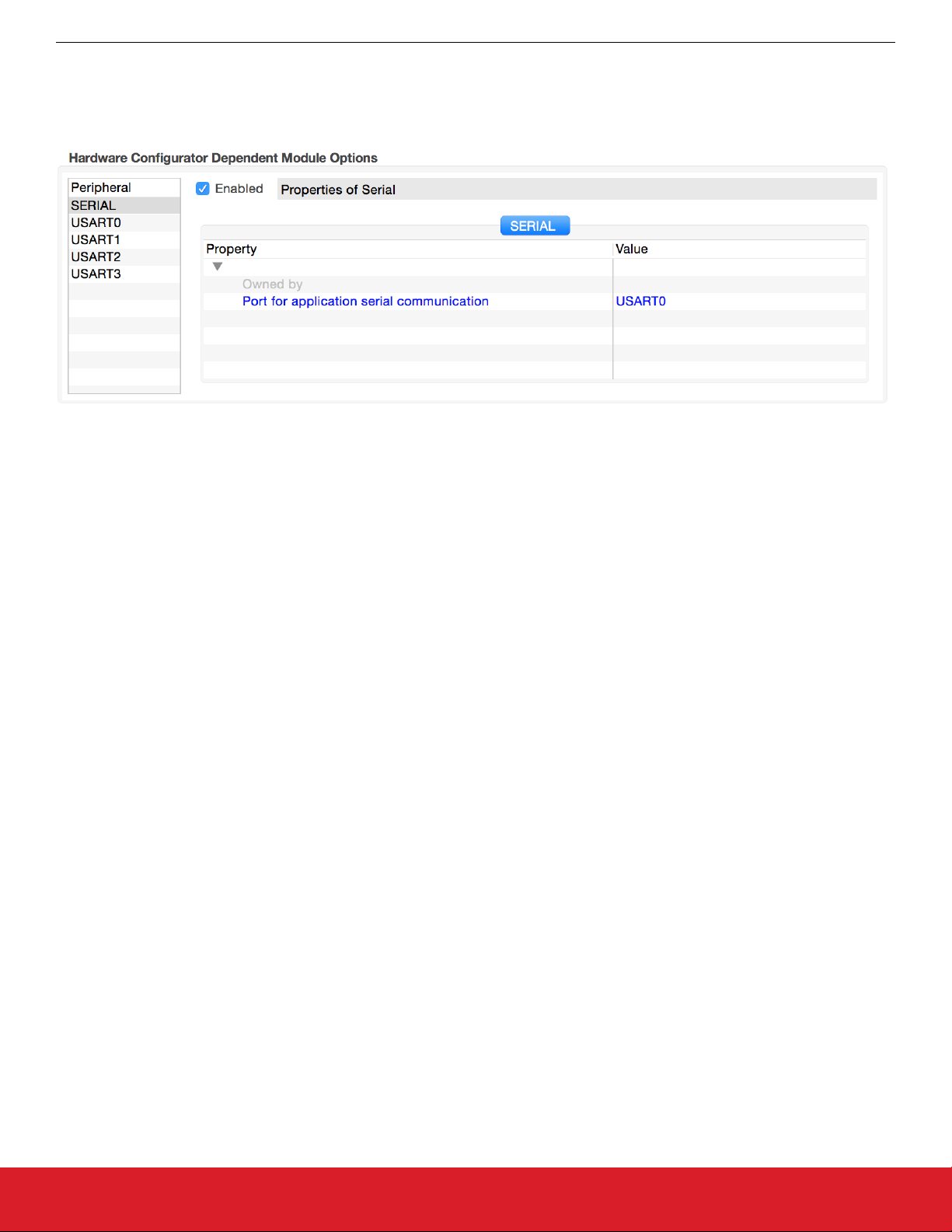
UG266: Silicon Labs Gecko Bootloader User’s Guide
Configuring the Gecko Bootloader
7.6 Hardware Configuration
The Gecko Bootloader AppBuilder framework integrates with the Hardware Configurator for configuration of pinout and other hardwarerelated settings. When Hardware Configurator configuration is available for an AppBuilder plugin, the relevant settings are shown in the
Hardware Configurator section of the AppBuilder plugin configuration.
Figure 7.3. Example of USART Configuration for UART Driver
The standalone Hardware Configurator User Interface can also be used to configure settings for Gecko Bootloader if desired.
While Hardware Configurator provides configuration for many different peripherals, the Gecko Bootloader uses only the following Hardware Configurator modules:
• SERIAL is used by the UART Driver plugin to configure baud rate, flow control mode and pinout.
• VCOM is used by the UART Driver plugin to enable the serial interface if necessary (only on Silicon Labs Wireless Starter Kits).
• EXTFLASH is used by the SPI Driver to configure frequency and pinout.
• SPINCP is used by the SPI Slave Driver to configure pinout.
• BTL_BUTTON is used by the GPIO Activation plugin.
• CMU HFXO frequency setting is used by the delay driver to calibrate timing if the core is running from the HFXO.
Other settings, like CMU oscillator configuration or DCDC configuration, are not taken into consideration by the default bootloader code.
If using these configuration settings is desired, the required code must be added in btl_main.c.
Note: While the delay driver uses the HFXO frequency setting from Hardware Configurator, the HFXO enable setting is not used to
initialize the HFXO on startup. This setting is only used when calling the bootloader through the Application Interface as described in
section 10. Application Interface, and the application has switched to the HFXO prior to calling the Bootloader Application Interface API.
silabs.com | Building a more connected world. Rev. 1.6 | 35
Page 36

UG266: Silicon Labs Gecko Bootloader User’s Guide
Configuring the Gecko Bootloader
7.7 Size Requirements for Different Bootloader Configurations for Series 1 Devices
Enabling different configuration options for the Gecko Bootloader changes the size of the resulting image. The following table shows a
list of example bootloader configurations and their resulting approximate size of the main bootloader. Note that any size above 14 kB
will be too large to fit in the bootloader area of flash of EFR32xG13, and that any size above 16 kB will be too large to fit in the bootloader area of flash on EFR32xG14 and EFM32TG11. This table was last updated for Gecko SDK Suite 2.5 (Gecko Bootloader 1.8),
and no guarantees are made that a configuration of a specific size with one SDK version will maintain that size in future releases.
Table 7.2. Bootloader Size Requirements
Base Configuration Enabled Options Size (kB)
XMODEM UART Default configuration 12.5
Secure boot, signed and encrypted upgrade 12.5
Secure boot, signed and encrypted upgrade, LZ4 compression 13.5
Secure boot, signed and encrypted upgrade, LZMA compression 17.5
Internal storage, single slot Default configuration 11
Secure boot, signed and encrypted upgrade 11
Secure boot, signed and encrypted upgrade, LZ4 compression 12
Secure boot, signed and encrypted upgrade, LZMA compression 16
Internal storage, multiple slots Default configuration 11.5
Secure boot, signed and encrypted upgrade 11.5
Secure boot, signed and encrypted upgrade, LZ4 compression 12.5
Secure boot, signed and encrypted upgrade, LZMA compression 16.5
SPI flash, single slot Default configuration 12
Secure boot, signed and encrypted upgrade 12
Secure boot, signed and encrypted upgrade, LZ4 compression 13
Secure boot, signed and encrypted upgrade, LZMA compression 17
SPI flash, multiple slots Default configuration 13
Secure boot, signed and encrypted upgrade 13
Secure boot, signed and encrypted upgrade, LZ4 compression 14
Secure boot, signed and encrypted upgrade, LZMA compression 18
BGAPI UART Default configuration 12
Secure boot, signed and encrypted upgrade 12
Secure boot, signed and encrypted upgrade, LZ4 compression 13
Secure boot, signed and encrypted upgrade, LZMA compression 17
EZSP SPI Default configuration 13
Secure boot, signed and encrypted upgrade 13
Secure boot, signed and encrypted upgrade, LZ4 compression 14
Secure boot, signed and encrypted upgrade, LZMA compression 18
silabs.com | Building a more connected world. Rev. 1.6 | 36
Page 37

UG266: Silicon Labs Gecko Bootloader User’s Guide
Simplicity Commander and the Gecko Bootloader
8. Simplicity Commander and the Gecko Bootloader
Simplicity Commander is a single, all-purpose tool to be used in a production environment. It is invoked using a simple CLI (Command
Line Interface that is also scriptable. You can use Simplicity Commander to perform these essential tasks:
• Generating key files for signing and encryption
• Signing application images for Secure Boot
• Creating GBL images (encrypted or unencrypted, signed or unsigned)
• Parsing GBL images
Simplicity Commander is used throughout the examples in the following sections. For more information on executing the commands to
complete these tasks, refer to UG162: Simplicity Commander Reference Guide.
Note: Simplicity Commander also offers a GUI (Graphical User Interface) that can be used in the lab for typical tasks such as flashing
device images. The functions described in this User Guide are performed from the CLI.
8.1 Creating GBL Files Using Simplicity Commander
To create an unsigned GBL file from an application myapp.s37, execute commander gbl create myapp.gbl --app myapp.s37.
To create an unsigned GBL file from a main bootloader upgrade mybootloader.s37, execute commander gbl create
mybootloader.gbl --bootloader mybootloader.s37. This file can be used with the standalone bootloader configurations of the
Gecko Bootloader.
To create an unsigned GBL file from a Secure Element, upgrade mySecureElement.seu, and execute commander gbl create
mySecureElement.gbl --seupgrade mySecureElement.seu. The Secure Element images, .seu, are provided by Silicon Labs and
can be found through Simplicity Studio. See section .
These commands can also be combined to create a single upgrade image, suitable for use with application bootloader configurations of
the Gecko Bootloader: commander gbl create myupgrade.gbl --app myapp.s37 --bootloader mybootloader.s37 --seupgrade
mySecureElement.seu.
silabs.com | Building a more connected world. Rev. 1.6 | 37
Page 38

UG266: Silicon Labs Gecko Bootloader User’s Guide
Gecko Bootloader Security Features
9. Gecko Bootloader Security Features
9.1 About Bootloader Image Security
Secure Boot and Secure Firmware Upgrade, discussed in the following sections, enable Gecko Bootloader to provide authenticity and
integrity checks on the Application image, which provides a sufficient level of security for many applications. However, in systems without a hardware root of trust, no process checks the authenticity or integrity of the Gecko Bootloader itself. Its security is provided solely
by the device hardware and the robustness of the software running on the device.
The native behavior of Firmware Upgrade will prevent accidental version rollback of Gecko Bootloader under normal usage conditions.
However, without a hardware root of trust, intentional downgrade attacks may be feasible. If a higher level of security assurance is required by the application, using a Series 2 device with hardware root of trust and anti-rollback protection is recommended. For more
information, refer to AN1218: Series 2 Secure Boot with RTSL.
9.2 About Application Image Security
The Gecko Bootloader can enforce security on two levels:
• Secure Boot refers to the verification of the authenticity of the application image in main flash on every boot of the device.
• Secure Firmware Upgrade refers to the verification of the authenticity of an upgrade image before performing a bootload, and optionally enforcing that upgrade images are encrypted.
silabs.com | Building a more connected world. Rev. 1.6 | 38
Page 39

UG266: Silicon Labs Gecko Bootloader User’s Guide
Gecko Bootloader Security Features
9.2.1 Secure Boot Procedure
When Secure Boot is enabled, the cryptographic signature of the application image in flash is verified on every boot, before the application is allowed to run. Secure Boot is not enabled by default in the example configurations provided by Silicon Labs, but enabling it is
highly recommended to ensure the validity and integrity of firmware images.
Signature Algorithms
The Gecko Bootloader supports the ECDSA-P256-SHA256 cryptographic signature algorithm. This is the ECDSA (elliptical curve digital
signature algorithm) of the SHA-256 digest of the application firmware image, using the NIST P-256 (secp256r1) curve.
Summary of Operation
1. On boot, the bootloader checks the application image for information about whether it is signed.
2. The type of signature and signature location is determined.
3. If the type of signature does not match the requirements of the bootloader, the bootloader enters device firmware upgrade mode
and prevents the application from running.
4. According to the chosen signature algorithm, the signature of the contents of flash from the beginning of the application to the location of the signature is compared to the signature at the signature location.
5. If the signatures do not match, the bootloader enters device firmware upgrade mode and prevents the application from running.
Secure Boot using ECDSA-P256-SHA256
For an image to be signed for Secure Boot, the application needs to contain a copy of the ApplicationProperties_t struct. This struct
contains information about which signature algorithm is used, and where to find the signature.
On every boot, the bootloader calculates the SHA-256 digest of the application image, from the beginning of the application to the start
of the signature. The signature of the SHA-256 digest is then verified using ECDSA-P256.
If the signature is valid, the application is allowed to boot. Else, the bootloader is entered, and an application upgrade is attempted if
one is available.
The public key used for signature verification is stored as a manufacturing token on Series 1 and EFR32xG22 devices. OnEFR32xG21
devices, the public key can either be stored as a manufacturing token or stored in the Secure Element One-time Programmable memory (OTP). Simplicity Commander can be used to generate a key pair and write the public key to the device. See UG162: Simplicity
Commander Reference Guide for more information.
Secure Boot with Application Rollback Protection
On every boot, the application version in the ApplicationData_t struct is stored at the end of the bootloader area in flash, which is used
to prevent applications from being downgraded. The application version can remain the same for upgrades. The bootloader will only
allow applications to increment its version 6 times by default. The bootloader can be upgraded after that to reset the stored application
versions and to allow application upgrades again. The allowed number of upgrades can be increased by modifying linkerfiles to reserve
an extra 4 bytes for each version and by increasing SL_GBL_APPLICATION_VERSION_STORAGE_CAPACITY from btl_bootload.c .
For Series 2 devices, this option is not applicable on devices with Secure Element configured to perform full page lock. If the
bootloader area in flash is locked by Secure Element, the bootloader will not be able to store the application versions in flash, and it
would continue without performing that function.
The application rollback prevention feature can be enabled in AppBuilder's Core plugin by selecting the Enable application rollback
protection option. The Minimum application version allowed option can be used to configure the minimum application version that
should be allowed to boot.
The application versions are stored in the bootloader area in flash. To properly protect the stored application versions, it is recommended to lock the bootloader flash by selecting the Prevent bootloader write/erase option in AppBuilder's Core plugin.
Secure Boot Using a Certificate
On Series 2 devices, a certificate-based secure boot operation is supported. The Certificate contains:
• Struct version: The version of the certificate structure.
• Public key: ECDSA-P256 public key, X and Y coordinates concatenated, used to validate the image.
• Certificate version: The version of the running certificate.
• Signature: ECDSA-P256 signature, used for the authentication of the public key and the certificate version.
The definition of the certificate struct can be found in api/application_properties.h.
silabs.com | Building a more connected world. Rev. 1.6 | 39
Page 40

UG266: Silicon Labs Gecko Bootloader User’s Guide
Gecko Bootloader Security Features
To utilize certificate-based secure boot, configure Secure Element to authenticate the bootloader image by configuring the certificatebased secure boot option in the Secure Element OTP. Configure the Gecko Bootloader to enable certificate-based secure boot in AppBuilder's Core plugin by selecting the Enable certificate support option. The Gecko Bootloader certificate must be signed by the private key pair of the public key stored in the Secure Element OTP. For more information on the key storage, refer to section 9.4.1 Key
Storage
silabs.com | Building a more connected world. Rev. 1.6 | 40
Page 41
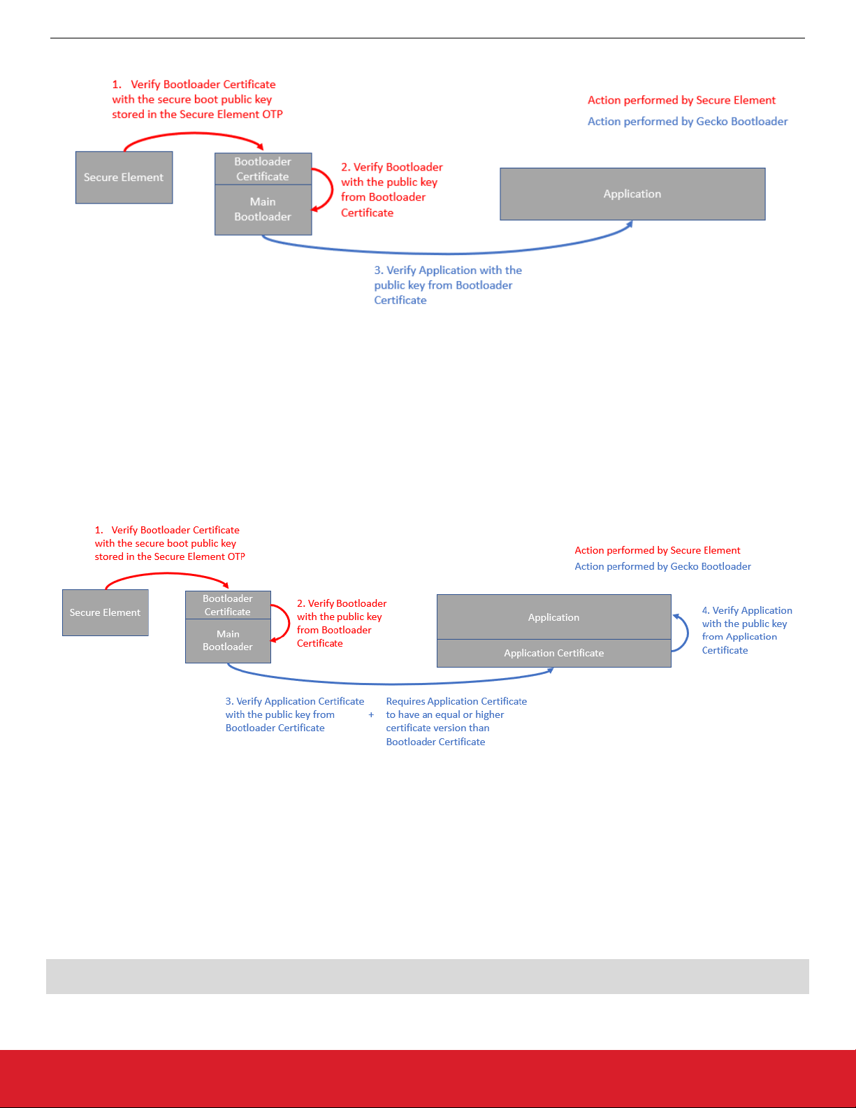
UG266: Silicon Labs Gecko Bootloader User’s Guide
Gecko Bootloader Security Features
The certificate-based secure boot procedure is illustrated in the following figure.
Figure 9.1. Certificate-Based Secure Boot Procedure
Once the certificate-based secure boot option on Secure Element is turned on, Secure Element verifies the Gecko Bootloader certificate. The public key stored in the certificate is used to validate the signature of the Gecko Bootloader. Secure Element will not accept
bootloader images without a certificate.
If only the secure boot option is enabled (not certificate-based) on Secure Element, and Secure Element identifies a certificate, the certificate will be used to validate the bootloader image. If the certificate version from the bootloader image is higher than 0 and it gets
verified once, Secure Element will never again accept direct signed bootloader images without a certificate.
The Gecko Bootloader will authenticate the direct signed application using the public key stored in the Gecko Bootloader certificate.
If the application contains a certificate, Gecko Bootloader will authenticate it. The procedure is illustrated in the following figure.
Figure 9.2. Advanced Certificate-Based Secure Boot Procedure
After authentication of the application certificate, Gecko Bootloader verifies the signature of the application using the public key from the
application certificate. In addition, Gecko Bootloader compares the Gecko Bootloader certificate version against the application certificate version. All application images with a certificate version lower than the certificate version of the Gecko Bootloader will be rejected.
Gecko Bootloader can be configured to only allow applications with certificate to boot in AppBuilder's Core plugin by selecting the Re-
ject direct signed images option.
The ApplicationProperties_t struct contains the certificate struct ApplicationCertificate_t. The certificate struct can be injected to images that contain an ApplicationProperties_t with ApplicationCertificate_t. To inject a certificate to an image, issue the following
command from Simplicity Commander:
commander convert <image file> --secureboot --keyfile <signing key> --certificate <certificate>
--outfile <signed image file with certificate>
silabs.com | Building a more connected world. Rev. 1.6 | 41
Page 42

UG266: Silicon Labs Gecko Bootloader User’s Guide
Gecko Bootloader Security Features
9.2.2 Secure Firmware Upgrade
The Gecko Bootloader supports a secure firmware upgrade process. This is achieved by using symmetric encryption to encrypt the
upgrade image, and asymmetric cryptography to sign the upgrade image in order to ensure its integrity and authenticity.
Encryption Algorithms
The Gecko Bootloader supports the AES-CTR-128 encryption algorithm. The GBL upgrade file is encrypted using 128-bit AES in Counter mode with a random nonce as the initial counter value.
The AES-128 key used for decryption, more commonly called the OTA decryption key, is stored as a manufacturing token on Series 1
and EFR32xG22 devices. On EFR32xG21 devices, the OTA decryption key can either be stored as a manufacturing token or stored in
the Secure Element OTP. To make use of the OTA decryption key stored in the Secure Element OTP, the Use symmetric key stored
in Secure Element storage option in AppBuilder’s Core plugin has to be selected. Simplicity Commander can be used to generate an
OTA decryption key and write the key to the device. See UG162: Simplicity Commander Reference Guide for more information. For
more information on storing the OTA decryption key on Series 2 devices, see AN1222: Production Programming of Series 2 Devices.
The Secure Element OTP key support depends on the SE Manager plugin, which is enabled by default.
Signature Algorithms
The Gecko Bootloader supports the ECDSA-P256-SHA256 cryptographic signature algorithm. This is the ECDSA signature of the
SHA-256 digest of the GBL upgrade file, using the NIST P-256 (secp256r1) curve.
Summary of Operation
Before starting a firmware upgrade process, the application can verify an image in storage by calling into the bootloader verification
functions.
During firmware upgrade, the GBL file is parsed, and if encrypted, decrypted on-the-fly. A GBL Signature Tag in the GBL file indicates
to the bootloader that the file is signed, and the signature is verified. If signature verification fails, the firmware upgrade process is aborted.
On Series 2 devices, Gecko Bootloader will authenticate the GBL signature tag using the public key stored in the bootloader certificate
if the Enable certificate support option is selected in AppBuilder's Core plugin. A GBL Certificate tag in the GBL file indicates to the
bootloader that the GBL certificate tag needs to be authenticated using the public key stored in the bootloader certificate. The certificate
version in the GBL certificate tag is compared with the bootloader certificate and only a version equal or higher than the bootloader
certificate is accepted. Once the GBL certificate tag is authenticated, the GBL file's signature is verified using the authenticated public
key from the GBL certificate tag. On EFRxG21 devices, the GBL certificate tag can also be signed by the private key pair of the public
key stored in the Secure Element OTP.
9.3 Using Application Image Security Features
In this example, we assume that a bootloader called bootloader-uart-xmodem has been built using the Application Builder in Simplicity Studio. For a Series 1 device, three files of interest have been generated in the output directory:
• bootloader-uart-xmodem.s37 – This file contains the main bootloader. Can be used for bootloader upgrade.
• bootloader-uart-xmodem-crc.s37 - This file contains the main bootloader with CRC32 checksum.
• bootloader-uart-xmodem-combined.s37 – This file contains the first stage and main bootloader with a CRC32 checksum in a single image. Can be used for manufacturing and initial deployment of the bootloader.
The relevant version can be flashed to the EFR32 using the Flash Programmer in Simplicity Studio, or using Simplicity Commander.
For Series 2 devices, only the main bootloader binary is generated.
This example provides two ways of signing the upgrade images. The first option uses Simplicity Commander to generate key material
and sign data. This is suitable for development. The second option uses an external signer, such as a dedicated Hardware Security
Module (HSM) to protect private key material and perform signing operations. Silicon Labs recommends using an HSM to safeguard
private keys.
silabs.com | Building a more connected world. Rev. 1.6 | 42
Page 43

UG266: Silicon Labs Gecko Bootloader User’s Guide
Gecko Bootloader Security Features
9.3.1 Generating Keys
In order to use the security features of the Gecko Bootloader, encryption and signing keys need to be generated. These keys must then
written to the EFR32 device. The encryption key is used with the GBL file for secure firmware upgrade. The signing keys are used both
with the GBL file for secure firmware upgrade and to sign the application image for Secure Boot.
Generating a Signing Key Using Simplicity Commander
commander util genkey --type ecc-p256 --privkey signing-key --pubkey signing-key.pub --tokenfile signing-keytokens.txt
This creates an ECDSA-P256 key pair for signing: signing-key contains the private key in PEM format, and must be kept secret from
third parties. This key will later be used to sign images and GBL files. signing-key.pub contains the public key in PEM format, and
can be used to verify GBL files using commander gbl parse. signing-key-tokens. txt contains the public key in token format, suitable
for writing to the EFR32 device.
Generating a Signing Key Using a Hardware Security Module
When using a Hardware Security Module, the private key is kept secret inside the HSM. According to the instructions from your HSM
vendor, have it generate an ECDSA-P256 key pair and export the public key in PEM format to the file signing-key.pub. Then use Simplicity Commander to convert the key to token format, suitable for writing to the EFR32 device.
commander gbl keyconvert --type ecc-p256 signing-key.pub --outfile signing-key-tokens.txt
Generating an Encryption Key
commander util genkey --type aes-ccm --outfile encryption-key
This creates an AES-128 key for encryption in the file encryption-key. The file has token format, making it suitable to write to the
EFR32 device using commander flash --tokenfile.
Writing Keys to the Device
To write the two token files containing the encryption key and public key as manufacturing tokens to the device, issue the following
command:
commander flash --tokengroup znet --tokenfile encryption-key --tokenfile signing-key-tokens.txt
9.3.2 Signing an Application Image for Secure Boot
If the bootloader enforces Secure Boot, the application needs to be signed in order to pass verification. On every boot, a SHA-256 digest of the application is calculated. The signature is verified using ECDSA-P256, with the same public key as for the GBL file signing.
Signature verification failure prevents the application from booting.
Application images should contain an ApplicationProperties_t struct declaring the application version, capabilities, and other metadata. If ApplicationProperties_t is missing, the application image cannot be signed. For more details on adding ApplicationProper-
ties_t, refer to section 10.1 Application Properties.
Using Simplicity Commander
Signing the application can be done with the command:
commander convert myapp.s37 --secureboot --keyfile signing-key --outfile myapp-signed.s37
Using a Hardware Security Module
The application can be prepared for signing by issuing the command:
commander convert myapp.s37 --secureboot --extsign --outfile myapp-for-signing.s37
Using an HSM, sign the output file myapp-for-signing.s37, and supply the resulting DER-formatted signature file signature.der back
to Simplicity Commander:
commander convert myapp-for-signing.s37 --secureboot --signature signature.der --verify signing-key.pub
--outfile myapp-signed.s37
silabs.com | Building a more connected world. Rev. 1.6 | 43
Page 44

UG266: Silicon Labs Gecko Bootloader User’s Guide
Gecko Bootloader Security Features
9.3.3 Creating a Signed and Encrypted GBL Upgrade Image File From an Application
To create a GBL file from an application, use commander gbl create.
Note that, as of this writing, secure application images can only be constructed through Simplicity Commander, not through the configuration options available through AppBuilder.
Application images should contain an ApplicationProperties_t struct declaring the application version, capabilities, and other metadata. If ApplicationProperties_t is missing, the application image cannot be signed. For more details on adding ApplicationProper-
ties_t, refer to section 10.1 Application Properties.
Using Simplicity Commander to Sign
For an application called myapp.s37, use:
commander gbl create myapp.gbl --app myapp.s37 --sign signing-key --encrypt encryption-key
This single command performs three actions:
• Creates a GBL file
• Encrypts the GBL file
• Signs the GBL file
If Secure Boot is also desired, the application must be signed using commander convert --secureboot prior to creating the GBL.
Using a Hardware Security Module to Sign
For an application called myapp-signed.s37, which has previously been signed for Secure Boot, use:
commander gbl create myapp-for-signing.gbl --app myapp-signed.s37 --extsign --encrypt encryption-key
This command performs the following actions:
• Creates a partial GBL file
• Encrypts the partial GBL file
• Prepares the partial GBL file for signing by an external signer
Using an HSM, sign the output file myapp-for-signing.gbl.extsign, and supply the resulting DER-formatted signature file signa-
ture.der back to Simplicity Commander:
commander gbl sign myapp-for-signing.gbl.extsign --signature signature.der --verify signing-key.pub --outfile
myapp.gbl
The GBL file is not valid until the signature has been applied using gbl sign.
9.4 System Security Considerations
The Gecko bootloader security features can be used to create a secure device, but do not create a secure system by themselves. This
section goes over considerations that need to be taken when designing a secure system where the Gecko Bootloader is a component.
9.4.1 Key Storage
On Series 1 devices, the decryption and public sign keys used by the Gecko bootloader are stored in the Lockbits page in flash. To
prevent a rogue application from being able to change or wipe the keys, the Lockbits page should be write protected after the keys have
been written in manufacturing.
On Series 2 devices, the decryption key and the sign key used by the Gecko Bootloader can either be stored in the topmost page of the
main flash or in the Secure Element OTP. The decryption key can be provisioned in the Secure Element OTP using Simplicity
Commander or using the Secure Element Mailbox interface. The keys are not accessible from the user applications on EFR32xG22
devices, which means that the keys used by Gecko Bootloader need to be stored in the topmost page of the main flash. Once a key
value has been programmed into the Secure Element OTP, it cannot be changed. For more details, refer to AN1218: Series 2 Secure
Boot with RTSL and UG162: Simplicity Commander Reference Guide.
The default behavior of the Gecko Bootloader is to use the sign key stored in the Secure Element OTP to perform the signature verification. If the sign key is not provisioned, the Gecko Bootloader will try to use the public sign key stored in the topmost page of the main
flash. This fallback mechanism can be disabled by unchecking the “Allow use of public key from manufacturing token storage” plugin
option from the Core plugin in AppBuilder.
silabs.com | Building a more connected world. Rev. 1.6 | 44
Page 45

UG266: Silicon Labs Gecko Bootloader User’s Guide
Gecko Bootloader Security Features
9.4.2 Write-Protecting the Bootloader
By default, the region in flash used by the Gecko bootloader is readable and writeable. The region needs to stay readable in order for
the Application Interface to be able to interact with the bootloader. Immediately after reset, the region also needs to be writable in order
to be able to perform bootloader upgrades.
Series 1
It is possible to write-protect the bootloader region on EFR32xG12 and newer. This is done by setting the write-once MSC_BOOTLOADERCTRL_BLWDIS bit on every bootup on Series 1 devices. The pages are write-protected until the next reboot. This is done by the
Gecko bootloader main stage if the “Prevent bootloader write/erase” plugin option is enabled in the Core plugin in AppBuilder.
On EFR32xG1, where the bootloader resides in main flash rather than the information block, the BLWDIS option does not exist. On
EFR32xG1, the first flash page containing the first stage bootloader can be write-protected with a Page Lock word, using commander
device protect --write --range 0x0:+0x800. If bootloader upgrades are to be supported, the pages containing the main bootload-
er need to stay writeable.
Note: Setting MSC_BOOTLOADERCTRL_BLWDIS will also prevent debuggers from flashing a new bootloader. This means that debug tools that do not completely halt and reset the target device before re-flashing might fail to flash the new bootloader, as the flash is
write-protected. If you are unsure whether your debug tools will handle this gracefully, Silicon Labs recommends keeping this setting
disabled during development, and enabling it before going into production. If your debug tools halt and reset the target device before
flashing, this is not an issue, and Silicon Labs recommends enabling this setting early in the development cycle.
Series 2
On Series 2 devices, the write-once MSC_PAGELOCKx register is used to write-protect the pages used by the bootloader if the “Prevent bootloader write/erase” plugin option is enabled in the Core plugin in AppBuilder. The pages are write-protected until the next reboot.
9.4.3 Write-Protecting the Application
On Series 2 devices, it is also possible to write-protect the application. When the plugin option “Prevent write/erase of verified application” is enabled, the bootloader will write-protect the pages used by the application after successfully verifying the application signature,
before allowing the application to start. This option is only available when Secure Boot of the application is enabled. The MSC_PAGELOCKx register is used to protect the pages, and the write protection lasts until the next reboot.
9.4.4 Debug Access
Series 1
To prevent debugger access to the Series 1 devices, the Debug Lock word needs to be written. Device recovery after enabling the
Debug Lock is possible, but will erase the main flash and the Lockbits page. This will erase the main application and the key material
stored in the Lockbits page. The Userdata page and bootloader area will survive Debug Unlock, so secrets should not be stored in
these locations. To debug lock the device, issue commander device lock --debug enable. The AAP Lock can be used to permanently lock the debug port. This also prevents Debug Unlock. To AAP lock the device, please see the reference manual for your device
for the address location of the AAP lock word, and use commander flash --patch to write the appropriate value to this address.
Series 2
On Series 2 devices, debugger access can be prevented through Secure Element. Debugger access can be re-enabled after enabling
the Debug Lock by issuing device erase. To debug-unlock the device, issue commander device lock --debug disable from Simplicity Commander. This also erases the main flash, which results in the top page of main flash that stores the encryption and signing keys
being erased. To permanently lock the debug port, the device erase disable command can first be issued through Secure Element.
Thereafter, the debug lock command can be issued to the Secure Element. For more details, refer to AN1190: EFR32xG21 Secure
Debug.
Disabling Debug Access from Software
The software APIs DBG_DisableDebugAccess(dbgLockModeAllowErase) and DBG_DisableDebugAccess(dbgLockModePermanent)
from the EMLIB DBG module can be used from the application to lock the debug interface.
silabs.com | Building a more connected world. Rev. 1.6 | 45
Page 46

UG266: Silicon Labs Gecko Bootloader User’s Guide
Application Interface
10. Application Interface
The bootloader has an application interface exposed through a function table in the bootloader. The application interface provides APIs
to use bootloader functions for storing and retrieving upgrade images, and verifying their integrity. APIs to reboot into the bootloader are
also provided. For details see the Gecko Bootloader API Reference, shipped with the SDK in the platform/bootloader/documentation
folder.
If you are not using a protocol stack from Silicon Labs, the api/btl_interface.h header provides the bootloader application interface API.
If you are using a protocol stack from Silicon Labs, the recommended bootloader interface API for the specific protocol stack should be
used instead. The following files provide the implementation of the bootloader interface:
api/btl_interface.c (common interface)
api/btl_interface_storage.c (interface to storage functionality)
The application interface consists of functions that can be included into the customer application, and that communicate with the bootloader through the MainBootloaderTable_t. This table contains function pointers into the bootloader. The 10th word of the bootloader
contains a pointer to this structure, allowing any application to easily locate it. Using the wrapper functions provided in the Bootloader
Interface API is preferred over accessing the bootloader table directly. Modules include:
• Application Parser Interface: Application interface for interfacing with the bootloader image parser.
• Application Storage Interface: Application interface for interfacing with the bootloader storage. The Storage Interface is only available on bootloaders that support the storage interface.
• Common Application Interface: Generic application interface available on all versions of the bootloader, independently of which
plugins are present.
10.1 Application Properties
Application images should contain an ApplicationProperties_t struct declaring the application version, capabilities, and other metadata. Simplicity Commander extracts the metadata contained in this structure from the application and places it in the GBL upgrade file
GBL Application Tag. If the structure is not present in the application, Simplicity Commander will raise an error. The ApplicationProperties_t struct can be added to the application images by declaring the struct with the name sl_app_properties, as the startup files
provided by Silicon Labs contain a reference to the struct by that name. The contents of this tag can be extracted from a GBL file by a
running application using the Application Storage interface. Note that the GBL Application Tag will only be added if the GBL file contains an application image, not if the GBL file only contains a bootloader upgrade or metadata.
The structure in the application is also used to declare whether the application image is signed, and what type of signature is used. This
information is added by Simplicity Commander when signing the image using commander convert (--secureboot, --extsign or --
signature). In order for the bootloader to locate the ApplicationProperties_t struct, if not already done by the linker, Simplicity
Commander modifies word 13 of the application to insert a pointer to the ApplicationProperties_t struct when signing the application
image for Secure Boot.
silabs.com | Building a more connected world. Rev. 1.6 | 46
Page 47

UG266: Silicon Labs Gecko Bootloader User’s Guide
Application Interface
10.2 Error Codes
Most Gecko bootloader APIs return error codes. The following table lists the groups of error codes that may be returned. The full list of
error codes within each group can be found in api/btl_errorcode.h in the platform/bootloader directory of the SDK, as well as in the API
Reference.
ID Description
0x0 OK
0x01xx Initialization error
0x02xx Image verification error
0x04xx Storage error
0x05xx Bootload error
0x06xx Security error
0x07xx Communication error
0x09xx XMODEM parser error
0x10xx GBL file parser error
0x11xx SPI slave driver error
0x12xx UART driver error
0x13xx Compression error
silabs.com | Building a more connected world. Rev. 1.6 | 47
Page 48

Smart.
Connected.
Energy-Friendly.
Products
www.silabs.com/products
Disclaimer
Silicon Labs intends to provide customers with the latest, accurate, and in-depth documentation of all peripherals and modules available for system and software implementers using or
intending to use the Silicon Labs products. Characterization data, available modules and peripherals, memory sizes and memory addresses refer to each specific device, and "Typical"
parameters provided can and do vary in different applications. Application examples described herein are for illustrative purposes only . Silicon Labs reserves the right to make changes without
further notice to the product information, specifications, and descriptions herein, and does not give warranties as to the accuracy or completeness of the included information. Without prior
notification, Silicon Labs may update product firmware during the manufacturing process for security or reliability reasons. Such changes will not alter the specifications or the performance
of the product. Silicon Labs shall have no liability for the consequences of use of the information supplied in this document. This document does not imply or expressly grant any license
to design or fabricate any integrated circuits. The products are not designed or authorized to be used within any FDA Class III devices, applications for which FDA premarket approval is
required, or Life Support Systems without the specific written consent of Silicon Labs. A "Life Support System" is any product or system intended to support or sustain life and/or health,
which, if it fails, can be reasonably expected to result in significant personal injury or death. Silicon Labs products are not designed or authorized for military applications. Silicon Labs
products shall under no circumstances be used in weapons of mass destruction including (but not limited to) nuclear, biological or chemical weapons, or missiles capable of delivering
such weapons. Silicon Labs disclaims all express and implied warranties and shall not be responsible or liable for any injuries or damages related to use of a Silicon Labs product in such
unauthorized applications.
Trademark Information
Silicon Laboratories Inc.®, Silicon Laboratories®, Silicon Labs®, SiLabs® and the Silicon Labs logo®, Bluegiga®, Bluegiga Logo®, ClockBuilder®, CMEMS®, DSPLL®, EFM®, EFM32®,
EFR, Ember®, Energy Micro, Energy Micro logo and combinations thereof, "the world’s most energy friendly microcontrollers", Ember®, EZLink®, EZRadio®, EZRadioPRO®, Gecko®,
Gecko OS, Gecko OS Studio, ISOmodem®, Precision32®, ProSLIC®, Simplicity Studio®, SiPHY®, Telegesis, the Telegesis Logo®, USBXpress® , Zentri, the Zentri logo and Zentri DMS, ZWave®, and others are trademarks or registered trademarks of Silicon Labs. ARM, CORTEX, Cortex-M3 and THUMB are trademarks or registered trademarks of ARM Holdings. Keil is a
registered trademark of ARM Limited. Wi-Fi is a registered trademark of the Wi-Fi Alliance. All other products or brand names mentioned herein are trademarks of their respective holders.
Silicon Laboratories Inc.
400 West Cesar Chavez
Austin, TX 78701
USA
Quality
www.silabs.com/quality
Support and Community
community.silabs.com
http://www.silabs.com
 Loading...