

Page 1
AN333
Debug FunctionsData Communication
PC Base Adapter Daughter Card
Silicon Labs IDE Debug Logic
ToolStick
Virtual Tools
UART
GPIO
MCU
Debug HW
UART & GPIO
External HW
USB
Card
Edge
TOOLSTICK VIRTUAL TOOLS USER’S GUIDE
RELEVANT DEVICES
All Silicon Labs MCUs.
1. Introduction
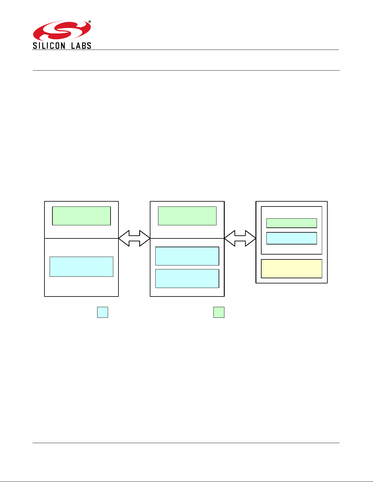
The ToolStick development platform consists of a ToolStick Base Adapter and a ToolStick Daughter card. The
ToolStick Virtual Tools application provides a set of tools for the PC that can be controlled via the UART serial
interface of the ToolStick Base Adapter. The ToolStick Virtual Tools application includes the following components:
To o lS ti c k Te rm i na l
ToolStick Virtual LCD
ToolStick Virtual Oscilloscope
Figure 1 shows a system block diagram of the ToolStick platform and the communication path between the
ToolStick Virtual Tools application and the MCU firmware.
Figure 1. ToolStick Development Platform Block Diagram
2. Getting Started
The ToolStick Virtual Tools installer can be downloaded from www.silabs.com/mcuniversity. This installer includes
the following components:
ToolStick Virtual Tools
Documentation
PCB files
ToolStick Virtual Tools interface libraries
Code examples
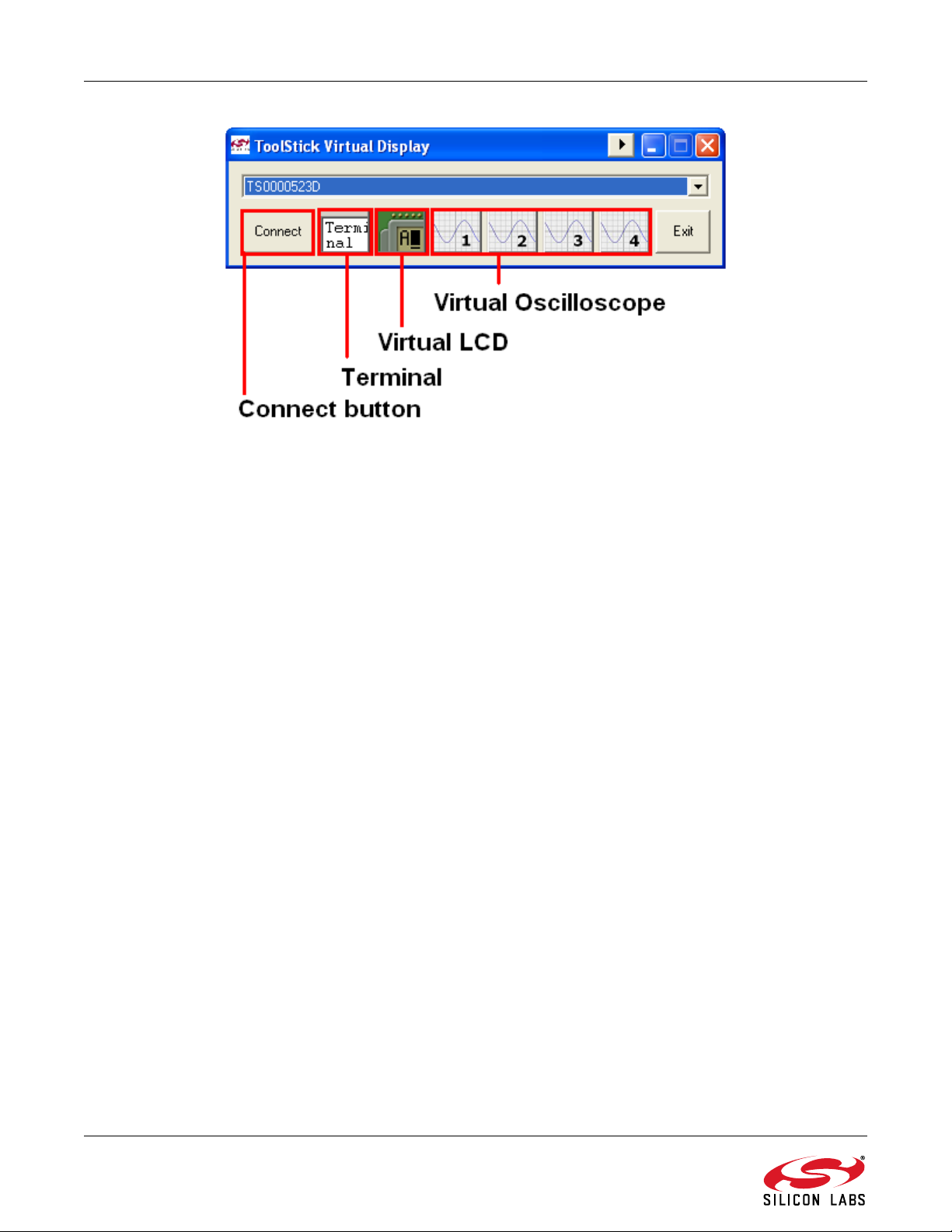
Figure 2 shows the ToolStick Virtual Tools launch window from which each of the individual tools can be launched.
Rev. 0.2 4/20 Copyright © 2020 by Silicon Laboratories AN333
Page 2
AN333
Figure 2. ToolStick Virtual Tools
2.1. System Requirements
ToolStick Virtual Tools requirements consist of the following:
Pentium class host PC running Windows 2000 or newer.
One available USB port.
64 MB RAM and 40 MB free HD space recommended.
2.2. Software Installation
Download the ToolStick Virtual Tools installer from www.silabs.com/mcuniversity. Launch the installer, and follow
the prompts to complete the installation. The ToolStick Virtual Tools are installed to the following default location:
C:\SiLabs\MCU\ToolStick\UniversityDC\VirtualTools\.
If you plan to build and download code to the target MCU on the daughter card, you will need the Silicon
Laboratories Integrated Development Environment (IDE). This IDE integrates a source-code editor, a source-level
debugger, and an in-system Flash programmer. It is also available for download from the above website
(www.silabs.com/mcuniversity). See the ToolStick University Daughter Card User’s Guide included with the
ToolStick Virtual Tools for instructions on using the IDE. This document would be installed by default at
C:\SiLabs\MCU\ToolStick\UniversityDC\Documentation\.
Note: The ToolStick Base Adapter uses a USB connection to the PC, but does not require any external device drivers to be
installed. This is because the base adapter conforms to the USB Human Interface Device (HID) class, for which the
device drivers are supplied with the Windows OS (Windows 2000 or newer).
2 Rev. 0.2
Page 3

AN333
3. ToolStick Virtual Tools Interface Libraries
The following set of device interface functions implement an Application Programming Interface (API) on the target
MCU. Using these functions simplifies code development when interfacing with the ToolStick Virtual Tools. The API
is provided in the form of precompiled libraries compiled under the Keil (TS_vInterface_Keil.LIB) and SDCC
(TS_vInterface_SDCC.LIB) toolsets. All functions in the interface library are declared in the header file,
TS_vInterface.h. In order to make use of these libraries, device firmware must be developed using one of these
toolsets, with the appropriate library included in the build. The available interface functions are:
SilabsInit020() - Initializes the C8051F020 MCU for use with the Virtual Tools
TerminalWrite() - Writes a byte to the ToolStick Terminal
TerminalRead() - Reads a byte from the ToolStick Terminal
LCD_ControlWrite() - Writes a control byte to the Virtual LCD
LCD_ControlRead() - Reads a control byte from the Virtual LCD
LCD_DataWrite() - Writes a data byte to the Virtual LCD
LCD_DataRead() - Reads a data byte from the Virtual LCD
ScopeClearBuffer() - Clears the Virtual Oscilloscope data buffer
ScopeSampleWrite() - Writes a sample value to a Virtual Oscilloscope channel
Lib_VersionRead() - Returns the ToolStick Virtual Tools interface library version
Each of these functions is described in detail in the following sections. The interface libraries are included in the
ToolStick Virtual Tools installer and are installed to the following default location:
C:\SiLabs\MCU\ToolStick\UniversityDC\Interface_Libraries\. See "Appendix A—ToolStick Virtual Tools Interface
Library Details" on page 10 for more details about the interface libraries.
3.1. SilabsInit020
Description: This function initializes the C8051F020 MCU for use with the ToolStick Virtual Tools. The MCU
system clock is configured to use the external 22.1184 MHz crystal present on the ToolStick University daughter card. The crystal is required for proper UART communication. The UART is configured for a baud rate of 230400 bps with a data format of 8-N-1 (8 data bits, No parity,
1 stop bit). Timer 1 is used as the baud rate generator. The Port I/O crossbar is enabled. The
port pin, P0.0 (TX), is configured as a push-pull output, and the port pin, P0.1 (RX), is configured
as a digital input.
Supported Devices: C8051F020
Prototype: void SilabsInit020 (void)
Parameters: None.
Return Value: None.
3.2. Lib_VersionRead
Description: This function reads a version number of the ToolStick Virtual Tools interface library.
Supported Devices: All Silicon Labs MCUs. See Appendix A.
Prototype: uint8_t Lib_VersionRead (void)
Parameters: None.
Return Value: Returns an unsigned 8-bit value indicating the library version.
Rev. 0.2 3
Page 4
AN333
4. ToolStick Terminal
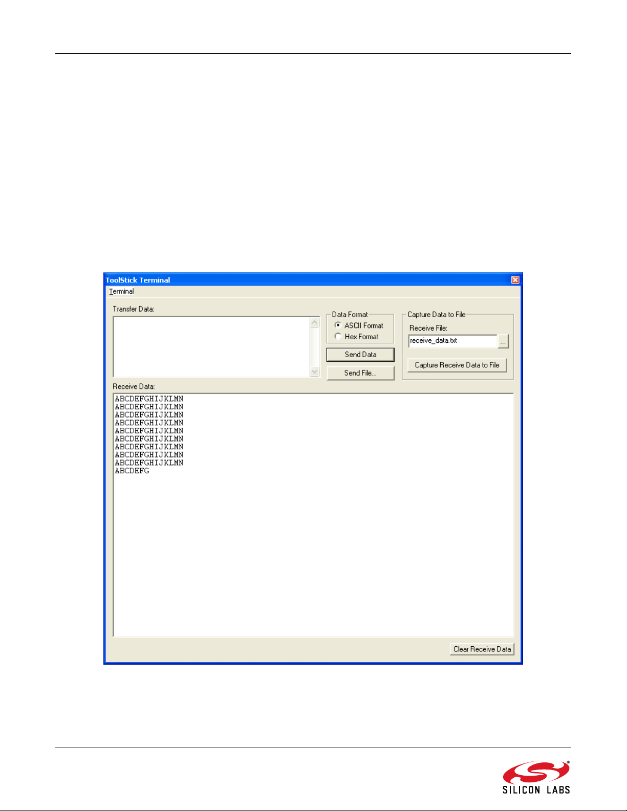
The ToolStick Terminal program provides the standard terminal interface to the target microcontroller's UART.
However, instead of requiring the usual RS-232 and COM port connection, the ToolStick Terminal uses the USB
interface of the ToolStick Base Adapter to provide the same functionality. In addition to the standard terminal
functions (send file, receive file), two GPIO pins on the target microcontroller can be controlled using the Terminal
for RTS/CTS handshaking. The UniDC_VirtualTools_Demo example code included with the ToolStick Virtual
Tools installer illustrates the use of this application. See "7. Library Files, Header Files, and Code Examples" on
page 9 to locate this example.
Note: The ToolStick Terminal application integrated within the ToolStick Virtual Tools application differs from the standalone
ToolStick Terminal application available from www.silabs.com/toolstick. In the case of the Terminal in Virtual Tools, the
baud rate is fixed at 230400 bps and is set up for RTS/CTS handshaking. These two options cannot be changed for any
of the ToolStick Virtual Tools applications.
The following sections describe the two Terminal interface functions included in the ToolStick Virtual Tools Interface
Library. Figure 3 shows the ToolStick Terminal application.
Figure 3. ToolStick Terminal Application
4 Rev. 0.2
Page 5

4.1. TerminalRead
Description: This function reads a byte from the ToolStick Terminal.
Supported Devices: All Silicon Labs MCUs. See Appendix A.
Prototype: uint8_t TerminalRead (void)
Parameters: None.
Return Value: Returns an unsigned 8-bit value read from the ToolStick Terminal.
4.2. TerminalWrite
Description: This function writes a byte to the ToolStick Terminal.
Supported Devices: All Silicon Labs MCUs.
See " Appendix A—ToolStick Virtual Tools Interface Library Details" on page 10.
Prototype: void TerminalWrite (uint8_t SendChar)
Parameters: 1. SendChar—8-bit value to be sent to the ToolStick Terminal
Return Value: None.
AN333
Rev. 0.2 5
Page 6

AN333
5. ToolStick Virtual LCD
The ToolStick Virtual LCD (Liquid Crystal Display) offers a virtual LCD with a serial interface on the PC. This
enables learning how to interface with a serial LCD without the additional hardware cost of an actual LCD. Figure 4
shows the Virtual LCD as it appears on the PC. The following sections describe the four Virtual LCD interface
functions included in the ToolStick Virtual Tools Interface Library
Figure 4. ToolStick Virtual LCD Application
5.1. LCD_ControlRead
Description: This function reads a control byte from the Virtual LCD.
Supported Devices: All Silicon Labs MCUs.
See " Appendix A—ToolStick Virtual Tools Interface Library Details" on page 10.
Prototype: uint8_t LCD_ControlRead (void)
Parameters: None.
Return Value: Returns an unsigned 8-bit value read from the Virtual LCD.
6 Rev. 0.2
Page 7

AN333
5.2. LCD_ControlWrite
Description: This function writes a control byte to the Virtual LCD. The control commands that can be sent to
the Virtual LCD are listed in Table 1.
Supported Devices: All Silicon Labs MCUs.
See " Appendix A—ToolStick Virtual Tools Interface Library Details" on page 10.
Prototype: void LCD_ControlWrite (uint8_t SendChar)
Parameters: 1. SendChar—8-bit value to be sent to the Virtual LCD.
Return Value: None.
.
SendChar Value Description
Table 1. LCD Control Commands
0x0C Display ON, Cursor OFF
0x01 Clear LCD
0x06 Entry mode increment without shift
5.3. LCD_DataRead
Description: This function reads a data byte from the Virtual LCD.
Supported Devices: All Silicon Labs MCUs.
See " Appendix A—ToolStick Virtual Tools Interface Library Details" on page 10.
Prototype: uint8_t LCD_DataRead (void)
Parameters: None.
Return Value: Returns an unsigned 8-bit value read from the Virtual LCD.
5.4. LCD_DataWrite
Description: This function writes a data byte to the Virtual LCD.
Supported Devices: All Silicon Labs MCUs.
See " Appendix A—ToolStick Virtual Tools Interface Library Details" on page 10.
Supported Devices: void LCD_DataWrite (uint8_t SendChar)
Parameters: 1. SendChar—8-bit value to be sent to the Virtual LCD.
Return Value: None.
Rev. 0.2 7
Page 8

AN333
6. ToolStick Virtual Oscilloscope
The ToolStick Virtual Oscilloscope application allows the PC to be used as an oscilloscope by sending data points
to be plotted through the target MCU’s UART interface via the ToolStick Base Adapter. Data, such as analog
measurements from the MCU, can be sent to the virtual oscilloscope to be plotted. The virtual oscilloscope has four
channels and can plot data up to 12-bits wide. The 12-bit data is ORed with the 4-bit channel number and sent to
the PC as a 16-bit number. The following sections describe the two Virtual Oscilloscope interface functions
included in the ToolStick Virtual Tools interface library. Figure 5 shows the ToolStick Virtual Oscilloscope
application.
Figure 5. ToolStick Virtual Oscilloscope Application
6.1. ScopeClearBuffer
Description: This function clears the data in its buffer for the specified channel of the Virtual Oscilloscope.
Supported Devices: All Silicon Labs MCUs.
See " Appendix A—ToolStick Virtual Tools Interface Library Details" on page 10.
Supported Devices: void ScopeClearBuffer (uint8_t ChannelMask)
Parameters: 1. ChannelMask—8-bit value of the channel whose buffer needs to be cleared. Valid values are
between 0 and 3.
Return Value: None.
6.2. ScopeSampleWrite
Description: This function writes a sample value to the specified channel of the Virtual Oscilloscope.
Supported Devices: All Silicon Labs MCUs.
See " Appendix A—ToolStick Virtual Tools Interface Library Details" on page 10.
Supported Devices: void ScopeSampleWrite (uint8_t Channel, uint8_t sendValueMSB, uint8_t sendValueLSB)
1. Channel—8-bit value of the channel whose buffer needs to be cleared. Valid values are
between 0 and 3.
2. sendValueMSB—8-bit value that holds the most significant 4 bits of the 12-bit sample value.
3. sendValueLSB—8-bit value that holds the least significant 8 bits of the 12-bit sample value.
Return Value: None.
8 Rev. 0.2
Page 9

AN333
7. Library Files, Header Files, and Code Examples
The ToolStick Virtual Tools interface library (for SDCC and Keil toolsets), SFR definition header files for the
C8051F020 MCU, and code examples are included in the ToolStick Virtual Tools installer. This can be downloaded
and installed from www.silabs.com/mcuniversity. The files are installed at the following default location:
C:\SiLabs\MCU\ToolStick\UniversityDC\Firmware\. The examples included are UniDC_SimpleDemo,
UniDC_FeaturesDemo, and UniDC_VirtualTools_Demo. Open the *.wsp project from the Silicon Labs IDE using
the ProjectOpen Project menu option, and follow the instructions listed at the top of the C source file to try
these examples.
Rev. 0.2 9
Page 10

AN333
APPENDIX A—TOOLSTICK VIRTUAL TOOLS INTERFACE
L
IBRARY DETAILS
All the three ToolStick Virtual Tools applications share the same UART channel for data transfer. In order to
distinguish between the data going to the different ToolStick Virtual Tools applications, an escape character should
be added before the actual data byte indicating for which ToolStick Virtual Tools application the data is intended.
The ToolStick Virtual Tools interface library functions automatically add the appropriate escape character; so, there
is no need to add these extra characters when using those functions. As an alternative to the interface functions,
the ToolStick Virtual Tools can be accessed directly by adding the appropriate escape character before the UART
data. A list of escape characters and descriptions is included in Table 2.
Table 2. ToolStick Virtual Tools Escape Characters
Value Description
0x01 Prefix before sending a character to be written to the Terminal.
0x02 Prefix before trying to read a character from the Terminal.
0x17 Prefix before sending a control character to be written to the Virtual LCD.
0x18 Prefix before trying to read a control character from the Virtual LCD.
0x19 Prefix before trying to read a data byte from the Virtual LCD.
0x20 - 0x7F Values in this range are meant for the virtual LCD and can be sent without any
escape character prefix.
0x80 This is the mask for any Virtual Oscilloscope control characters. The most signif-
icant bit should be set for all these characters.
0x07 Channel 8 is used to send Virtual Oscilloscope commands.
0x01 Virtual Oscilloscope command to clear a channel buffer. For this command, the
first character sent should be 0xF1 [0x80 | (0x07 << 4) | 0x01], and the next
character sent should be the number of the channel whose buffer should be
cleared.
Note: All the interface library functions (except the SilabsInit020 function) can be used with all Silicon Labs MCUs as long as
the UART0 is set up for 230400 bps, 8-N-1. For devices with SFR Paging, the SFR page should be set to the UART0
page before calling any of the interface library functions. The only SFRs used by the interface functions (except the
SilabsInit020 function) are SBUF0, TI0, and RI0, which are located at the same SFR locations in all Silicon Labs MCUs.
10 Rev. 0.2
Page 11

Simplicity Studio
One-click access to MCU and
wireless tools, documentation,
software, source code libraries &
more. Available for Windows,
Mac and Linux!
IoT Portfolio
www.silabs.com/IoT
Disclaimer
Silicon Labs intends to provide customers with the latest, accurate, and in-depth documentation of all peripherals and modules available for system and software implementers using or
intending to use the Silicon Labs products. Characterization data, available modules and peripherals, memory sizes and memory addresses refer to each specific device, and "Typical"
parameters provided can and do vary in different applications. Application examples described herein are for illustrative purposes only . Silicon Labs reserves the right to make changes without
further notice to the product information, specifications, and descriptions herein, and does not give warranties as to the accuracy or completeness of the included information. Without prior
notification, Silicon Labs may update product firmware during the manufacturing process for security or reliability reasons. Such changes will not alter the specifications or the performance
of the product. Silicon Labs shall have no liability for the consequences of use of the information supplied in this document. This document does not imply or expressly grant any license
to design or fabricate any integrated circuits. The products are not designed or authorized to be used within any FDA Class III devices, applications for which FDA premarket approval is
required, or Life Support Systems without the specific written consent of Silicon Labs. A "Life Support System" is any product or system intended to support or sustain life and/or health,
which, if it fails, can be reasonably expected to result in significant personal injury or death. Silicon Labs products are not designed or authorized for military applications. Silicon Labs
products shall under no circumstances be used in weapons of mass destruction including (but not limited to) nuclear, biological or chemical weapons, or missiles capable of delivering
such weapons. Silicon Labs disclaims all express and implied warranties and shall not be responsible or liable for any injuries or damages related to use of a Silicon Labs product in such
unauthorized applications.
Trademark Information
Silicon Laboratories Inc.®, Silicon Laboratories®, Silicon Labs®, SiLabs® and the Silicon Labs logo®, Bluegiga®, Bluegiga Logo®, ClockBuilder®, CMEMS®, DSPLL®, EFM®, EFM32®,
EFR, Ember®, Energy Micro, Energy Micro logo and combinations thereof, "the world’s most energy friendly microcontrollers", Ember®, EZLink®, EZRadio®, EZRadioPRO®, Gecko®,
Gecko OS, Gecko OS Studio, ISOmodem®, Precision32®, ProSLIC®, Simplicity Studio®, SiPHY®, Telegesis, the Telegesis Logo®, USBXpress® , Zentri, the Zentri logo and Zentri DMS, ZWave®, and others are trademarks or registered trademarks of Silicon Labs. ARM, CORTEX, Cortex-M3 and THUMB are trademarks or registered trademarks of ARM Holdings. Keil is a
registered trademark of ARM Limited. Wi-Fi is a registered trademark of the Wi-Fi Alliance. All other products or brand names mentioned herein are trademarks of their respective holders.
Silicon Laboratories Inc.
400 West Cesar Chavez
Austin, TX 78701
USA
SW/HW
www.silabs.com/simplicity
Quality
www.silabs.com/quality
Support and Community
community.silabs.com
http://www.silabs.com
 Loading...