

Page 1
UG164: Thunderboard
Not Recommended for New Designs
React
(RD-0057-0201) User's Guide
TM
The Thunderboard™ React is a cloud-connected, Bluetooth
Smart-enabled, sensor-driven platform that enables customers to
demo, evaluate, and develop their own unique applications.
It leverages Silicon Labs’ BGM111 Bluetooth Smart module as a wireless system-on-achip (SoC) to collect to various sensor data and deliver it to the cloud through Bluetooth
Low Energy (BLE)-enabled iOS/Android mobile apps. This document provides an overview of the kit including hardware, software application, cloud platform, and mobile app.
It also contains instructions and guidelines to evaluate the simplicity of adding Blue-
tooth to your project to connect to the cloud.
®
KEY POINTS
• Low-cost, Bluetooth Smart solution that
collects and delivers data to the cloud
• Hardware includes BGM111 Bluetooth
Smart module linked to sensor inputs
• ThunderBoard React connects to BLEenabled iOS/Android mobile apps
•
Apps connect to a cloud-based multi-client,
real-time synchronization database
silabs.com | Smart. Connected. Energy-friendly. Rev. 1.3
Page 2
UG164: ThunderboardTM React (RD-0057-0201) User's Guide
Not Recommended for New Designs
1. Introduction
Thunderboard™ React is a low-cost, BLE solution that collects and delivers data to the cloud.
Introduction
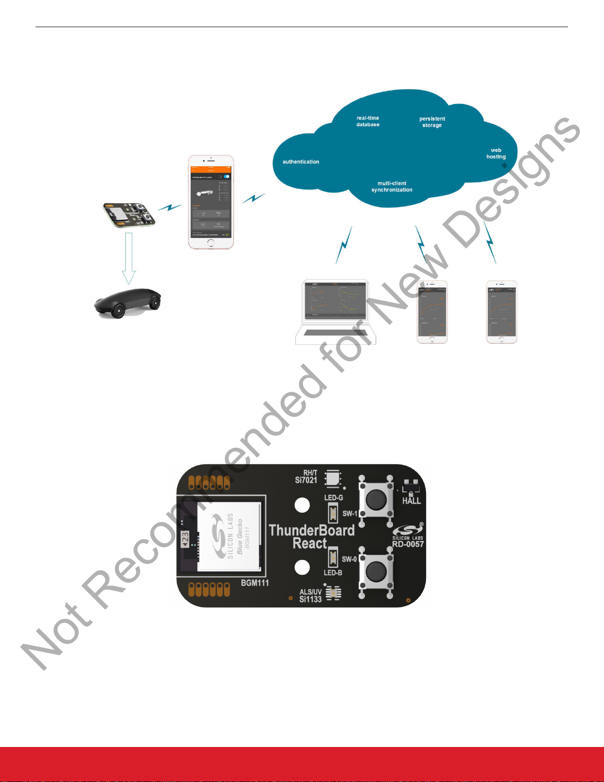
Figure 1.1. System Application Diagram
The Thunderboard React is a great demonstration and evaluation tool to easily add BLE connectivity to a sensor or actuator application. The mobile
or control the LED states on the Thunderboard React hardware. Individual components of the Thunderboard React can be easily integrated and modified in order to add BLE-to-cloud connectivity for a user’s particular application.
All instructions, collateral, and source files for this solution can be found here: http://www.silabs.com/thunderboardreact.
app seamlessly communicates between the Thunderboard and the cloud database to visualize sensor data collected
Figure 1.2. ThunderBoard React
silabs.com | Smart. Connected. Energy-friendly. Rev. 1.3 | 1
Page 3

UG164: ThunderboardTM React (RD-0057-0201) User's Guide
Not Recommended for New Designs
Quick Start
2. Quick Start
This section describes how to quickly get started using the Thunderboard React with its mobile apps and cloud database. For detailed
instructions, refer to Section 4. Operation.
1. Download the mobile app.
a. Links to the iOS and Android mobile app can be found here: http://www.silabs.com/thunderboard
2. Supply power to the Thunderboard React.
a. Remove the battery tab.
b. Set SW3 switch where its toggle is closest to Vbat.
3. Connect the Thunderboard React to the mobile app.
a. Launch the mobile app on the phone, ensuring the phone’s Bluetooth radio is enabled.
b. On the Thunderboard React, press the SW-0 button. The blue LED (LED-B) will blink to indicate it is sending a beacon adver-
tisement.
c. Locate the device on the app which should display “Thunderboard React #nnnnn”, and click on the device in the mobile app to
connect to it.
d. If the device successfully pairs, the mobile app displays available demos and the blue LED on the hardware will stop flashing.
4. Select the demo.
a. For this quick start, select the I/O demo.
b. Once the demo is activated, it will take you to the demonstration screen.
5. Use the demo.
a. Press the SW-0 and SW-1 on the Thunderboard React and witness its visual response along the top area of the phone
screen.
b. On the mobile app itself, press the two buttons in the middle and witness that the Thunderboard React's blue LED (LED-B)
and green LED (LED-G) are statically illuminated.
c. Press both buttons again on the mobile app to extinguish the LEDs.
6. Stream to the Cloud.
a. Ensure the mobile phone has the ability to connect to the internet either through Wi-Fi or cellular connection for this portion of
the demonstration.
b. While in the I/O demo, along the top portion of the screen, drag the toggle switch to activate cloud streaming.
c. Data is now being sent from Thunderboard React to the mobile app to a cloud database on the internet.
d. To see the live stream, select the share icon (up arrow in an open box) next to the toggle switch on the mobile app, and then
select the phone’s mobile browser. This will launch the browser, placing the mobile app in the background while still streaming
data to the cloud.
e. The switch and LED real-time data will now be shown in the browser.
f. While still connected, press the buttons on Thunderboard React and witness the resulting change in states on the cloud.
7. Share the Cloud stream session.
a. While streaming, in the mobile app, select the share icon and then select an email, message client, or social media tool. This
should launch the tool with a pre-populated message containing a hyperlink to the streaming session.
b. Send the message to another device client (such as a laptop or another mobile phone with a web browser).
c. From the device client, launch the hyperlink and witness the simultaneous cloud session being displayed on this device while
the original phone is connected to the Thunderboard React. The cloud platform supports real-time data synchronization across
multiple clients.
8. End the cloud stream.
a. Return to the mobile app and move the upper toggle switch to disable the cloud stream session.
9. Turn off the device.
a. On the Thunderboard React, move the SW3 toggle switch to where it is the closest to Vext.
10. Review the cloud session.
a. If emailed, this provided link will display the resulting summary of the cloud streaming session.
b. This link will be available for 30 days.
silabs.com | Smart. Connected. Energy-friendly. Rev. 1.3 | 2
Page 4
UG164: ThunderboardTM
Not Recommended for New Designs
React (RD-0057-0201) User's Guide
Overview
3. Overview
The Thunderboard React solution provides:
•
A low-cost, Bluetooth-enabled sensor platform
• Open-source, native iOS, and Android mobile apps
• A cloud database (Google Firebase) that supports multiple clients
This solution allows customers to demo, evaluate, and develop their own unique applications.
3.1 Part Number
The part number convention is RD-XXX-YYYY, where:
RD Reference Design
XXXX Reference Design Number
YYYY Reference Design Component
This document will use the reference design number (RD-XXXX) when describing the complete design, and the reference design component (RD-XXXX-YYYY) when describing a specific component.
The following table provides a description and PCB marking for each part number.
Note: Some cases lack
ber.
sufficient space on the PCB, and an internal “IST” marking appears on the PCB instead of the “RD” part num-
Table 3.1. Part Numbers and Description
Part Number PCB Marking Description
CARKIT N/A Cloud-connected, Bluetooth-enabled pinewood derby car kit with included
RD-0057-0101 Thunderboard React Evaluation Board
RD-0057-0201 N/A Thunderboard React Bluetooth Sensor Reference Design Kit with BGM111, Si7021,
Si7201, and Si1133.
RD-0057-0101 IST-A0057 Rev 2.0 Thunderboard React Bluetooth Sensor Evaluation Board with BGM111, Si7021,
Si7201, and Si1133.
3.2 Reference Design Kit
3.2.1 RD-0057-0201 Kit Contents
• Thunderboard React evaluation board
• Quick start card to obtain the latest design collateral
3.2.2 RD-0057-0101 Kit Contents
•
Thunderboard React evaluation board
• Car shell
• Pinewood car base
• Wheels and axles
• Metal screws and stand-offs
• Quick start card to explain assembly and obtain the latest design collateral
silabs.com | Smart. Connected. Energy-friendly. Rev. 1.3 | 3
Page 5

3.3 Hardware Features
Not Recommended for New Designs
The ThunderBoard React hardware platform contains the following features:
•
Silicon Labs Blue Gecko BGM111 Bluetooth® Smart Module
•
32-bit ARM® Cortex-M4 CPU
•
256 KB Flash
• 32 KB RAM
TX power: up to +8 dBm
•
• RX sensitivity down to –93 dBm
• Silicon Labs Si7021 relative humidity and temperature sensor
• Temperature sensor accuracy: ±0.4 °C
• Humidity sensor accuracy: ±3% RH
• I2C interface
• Silicon Labs Si1133 ambient light and UV sensor
• Ambient light sensor range: 1 to 128 kilo lux
• UV index sensor range: 1 to 11
• I2C interface
• Silicon Labs Si7201 omni-polar, hall-effect sensor
• Operating point: 30 Gauss max
• Release point: 10 Gauss min
• Push-pull output
• Invensense MPU-6500 6-axis motion sensor
• 3-axis accelerometer
• 3-axis gyroscope
• I2C interface
• Two momentary buttons (SW-0, SW-1)
• Blue and green LEDs (LED-B, LED-G)
• 10-pin 0.050”, 1.27 mm mini-simplicity debug connector
• PCB footprint for up to 8Mb external flash device
• Break-out pin pads to connect to BGM111 GPIOs
• CR2032 coin cell battery slot
UG164: ThunderboardTM React (RD-0057-0201) User's Guide
Overview
Figure 3.1. Thunderboard React Hardware Diagram
silabs.com | Smart. Connected. Energy-friendly. Rev. 1.3 | 4
Page 6

3.4 Thunderboard React Firmware Features
Not Recommended for New Designs
The Thunderboard React firmware application contains the following features:
• Pre-compiled and source application firmware
• Sleep mode for battery savings
Beacon notification to interface to a beacon-compatible mobile app
•
• Bluetooth-compatible GATT service profiles
3.5 ThunderBoard Mobile App Features
The Silicon Labs ThunderBoard mobile apps contains the following features:
• Bluetooth-compatible connectivity support
• Beacon notification support
• iOS app uses native Swift code
• Android app uses native Java code
• Source code can be obtained at: http://www.GitHub.com/SiliconLabs
3.6 ThunderCloud Software Features
The Thunderboard React’s web client contains the following features:
• Leverages Firebase by Google, a scalable cloud solution that can rapidly deploy:
• Real-time synchronization database capable of supporting multiple clients
• User authentication security
• Web hosting
• ThunderCloud uses ReactJS framework for its overall architecture:
• Leverages npm as a package manager
• Alt.js for the flux implementation
• React Router for routing within the app
• D3.js For data-driven charts
• LESS for CSS pre-processing
• Gulp for building and minifying code
• These tools and architecture allow for:
• Simultaneous connection of multiple Thunderboard React devices via mobile app
• Multiple device clients synchronously connected to a single cloud session
• Persistence storage of past cloud sessions (up to 30 days).
• Source code can be obtained at: http://www.GitHub.com/SiliconLabs.
UG164: ThunderboardTM React (RD-0057-0201) User's Guide
Overview
silabs.com | Smart. Connected. Energy-friendly. Rev. 1.3 | 5
Page 7
UG164: ThunderboardTM React (RD-0057-0201) User's Guide
Not Recommended for New Designs
Operation
4. Operation
This section describes the various operational modes of the Thunderboard React hardware, the Silicon Labs ThunderBoard mobile
apps, the Thundercloud database and how each interact to create a low-cost, BLE-enabled, cloud-connected solution. For this section,
the screen captures will be using the iOS mobile app even though the instructions apply to both mobile apps. For features where the
Android mobile app operates differently than iOS, these instructions will also be provided.
Open App
BLUETOOTH
BLUETOOTH
DISABLED
DISABLED
Prompts to
prompts to
enable BT
enable BT
DEVICE
SETTINGS
bluetooth
settings
NO DEVICE
FOUND
prompts to
turn on device
DEVICE(S)
FOUND
Beacon info
& connect
APP
SETTINGS
Personalize &
preferences
4.1 Download the Mobile Apps
Specific links to
the iOS AppStore and Google Play Store to obtain the free Silicon Labs ThunderBoard mobile apps can be found here:
http://www.silabs.com/thunderboard-react.
Beacon Notification
CHOOSE
DEMO
shows
available
demos
DEMO
shows current
data & cloud
stream option
CLOUD
SYNC
option to send
link or view
now
SEND LINK
choose SMS
or Email
Opens
default
browser
Figure 4.1. Mobile App and Cloud Flow Diagram
SEND SMS/
EMAIL
link to cloud,
link to more
info
SEND SMS/
EMAIL
link to cloud,
link to more
info
VIEW
CLOUD
SYNC
data over time
and summary
MORE INFO
Product
collateral,
code
4.2 Supply Power to the Thunderboard React
If present, remove the battery tab from the battery holder. Set the SW3 switch where its toggle is closest to Vbat to supply power to the
device. Setting the toggle closest to Vext will power-down the device. At power up, the device will enter a self-test mode. If it discovers
an error, it will emit alternating green and blue LEDs. For more information on the self-test, refer to the firmware section. If changing
CR2032 batteries, ensure the positive side of the battery (+) is aligned to the metal battery tab’s plus marking (+).
Figure 4.2. Thunderboard React with Battery Tab
The hardware can additionally be powered via the mini-simplicity debug connector (J3). To do this, ensure the SW3 switch is set to
where its toggle is closest to Vext.
silabs.com | Smart. Connected. Energy-friendly. Rev. 1.3 | 6
Page 8
4.3 Connect Thunderboard React to the Mobile App
Not Recommended for New Designs
UG164: ThunderboardTM React (RD-0057-0201) User's Guide
Operation
Once the mobile
to successfully pair them.
4.3.1 Launch the Mobile App
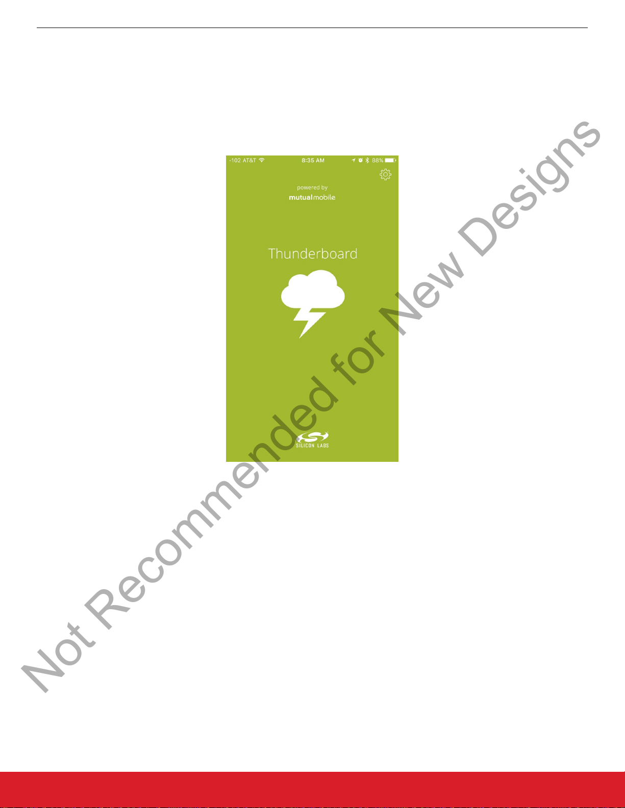
Upon selecting the Silicon Labs ThunderBoard icon on an iOS/Android mobile phone, the app will launch with this introduction screen
for a few seconds, and will then look for nearby Thunderboard React devices:
app is successfully installed on the phone and the hardware is powered, the following sub-sections will describe how
Figure 4.3. Mobile App Launch Screen
silabs.com | Smart. Connected. Energy-friendly. Rev. 1.3 | 7
Page 9
4.3.2 Enable Beacon Notification
Not Recommended for New Designs
UG164: ThunderboardTM React (RD-0057-0201) User's Guide
Operation
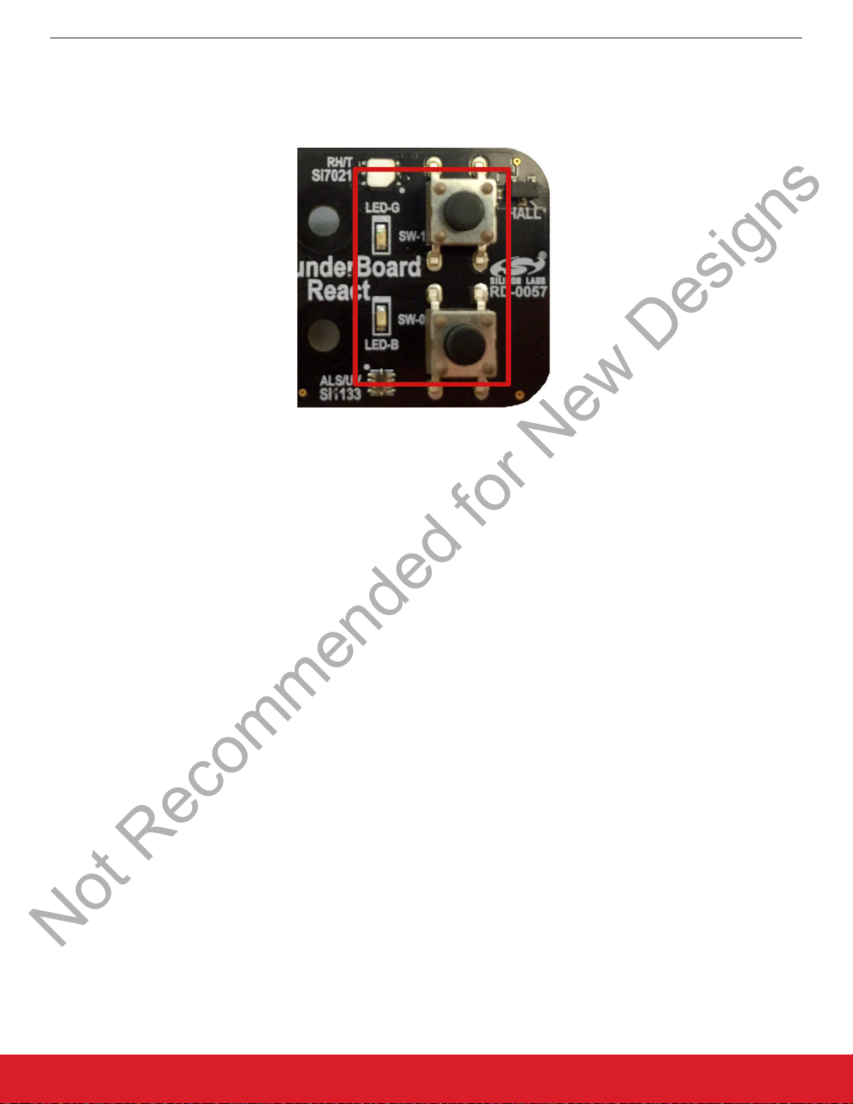
On the Thunderboard
beacon. To save power, the beacon will only be enabled for 30 seconds. If it is necessary to re-activate the BLE beacon, re-press one
of the buttons.
React, press either the SW-0 or SW-1 button. The LED-B will blink to indicate it is sending an advertisement
Figure 4.4. LEDs and Buttons on Thunderboard React
silabs.com | Smart. Connected. Energy-friendly. Rev. 1.3 | 8
Page 10
4.3.3 Looking for Devices
Not Recommended for New Designs
UG164: ThunderboardTM React (RD-0057-0201) User's Guide
Operation
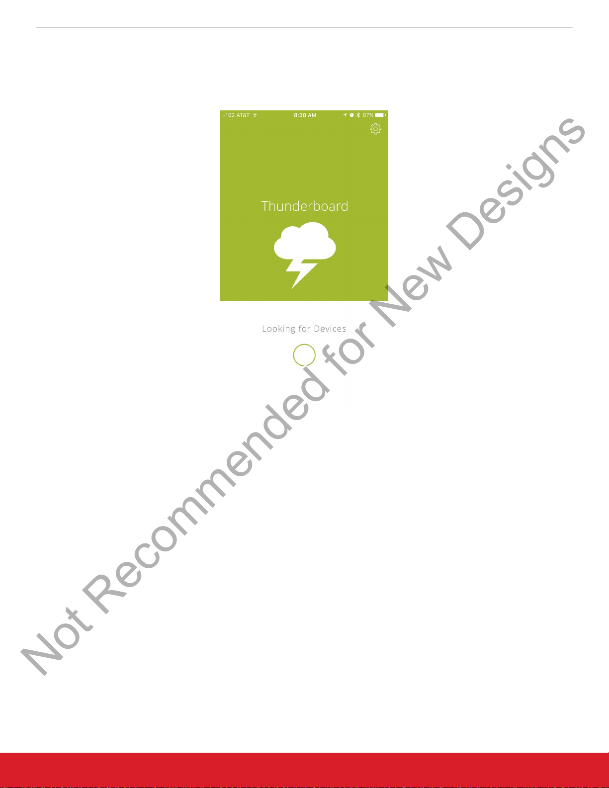
After the launch
screens should either have the message “Looking for Devices” or display the found device(s).
screen completes, the app will display various informal messages as it is looking for a ThunderBoard device. Valid
Figure 4.5. Valid Screens While the App Looks for Device(s)
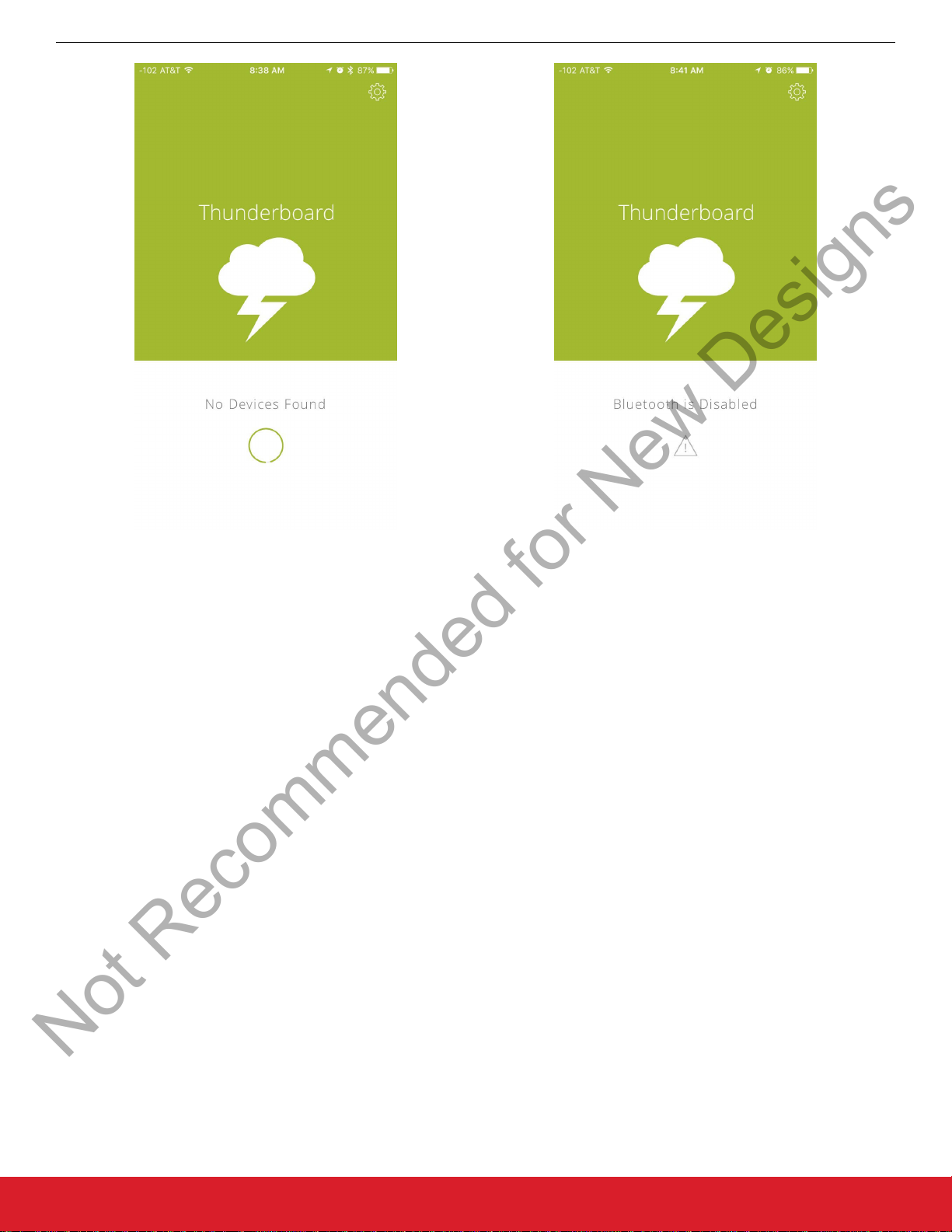
Once a device is found, it can be selected as described in the next section. The detected device will display its unique name and measured received signal level from the perspective of the mobile phone.
If “Bluetooth is Disabled” is displayed, go to the mobile phone’s settings and ensure its airplane mode is not enabled and the Bluetooth
radio is enabled. If “No Devices Found” is displayed, ensure the Thunderboard React is in nearby range, is powered, and its Blue LED
is flashing.
silabs.com | Smart. Connected. Energy-friendly. Rev. 1.3 | 9
Page 11
UG164: ThunderboardTM React (RD-0057-0201) User's Guide
Not Recommended for New Designs
Operation
Figure 4.6. Error Messages While Looking for Device(s)
silabs.com | Smart. Connected. Energy-friendly. Rev. 1.3 | 10
Page 12
UG164: ThunderboardTM React (RD-0057-0201) User's Guide
Not Recommended for New Designs
4.3.4 Selecting From Found Device(s)
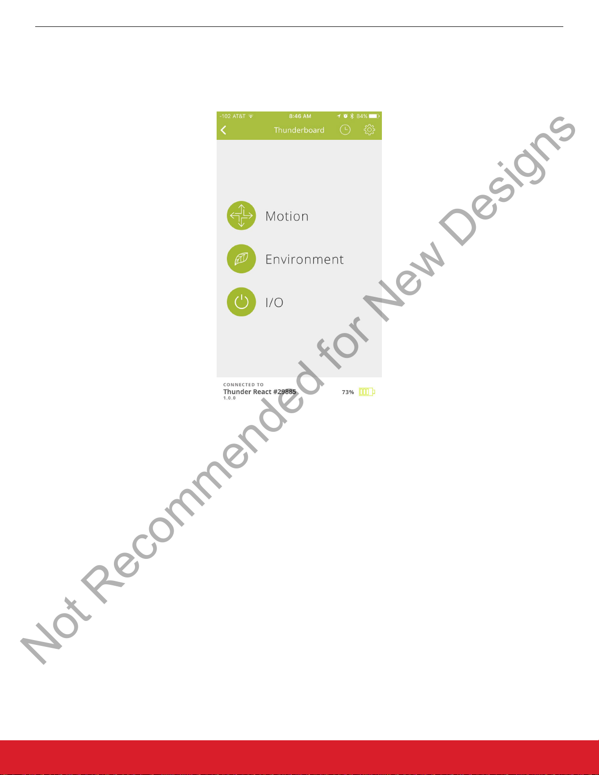
After Thunderboard React device(s) have been found, tap on the desired device to connect to it.
Operation
A successful connection
the blue LED should stop flashing and the green LED should flash once.
will display available demos, and the device’s information will show along the bottom border. On the hardware,
Figure 4.7. App Screen after Successful Connection
From this screen along the bottom border, the device’s unique name will display along with its estimated battery health. Clicking the
back arrow from this screen will disconnect (un-pair) the device from the mobile app.
To enable opening the app using the advertisement beacon, click on the gear icon for global settings, as described in the user app
settings section.
silabs.com | Smart. Connected. Energy-friendly. Rev. 1.3 | 11
Page 13
UG164: ThunderboardTM React (RD-0057-0201) User's Guide
Not Recommended for New Designs
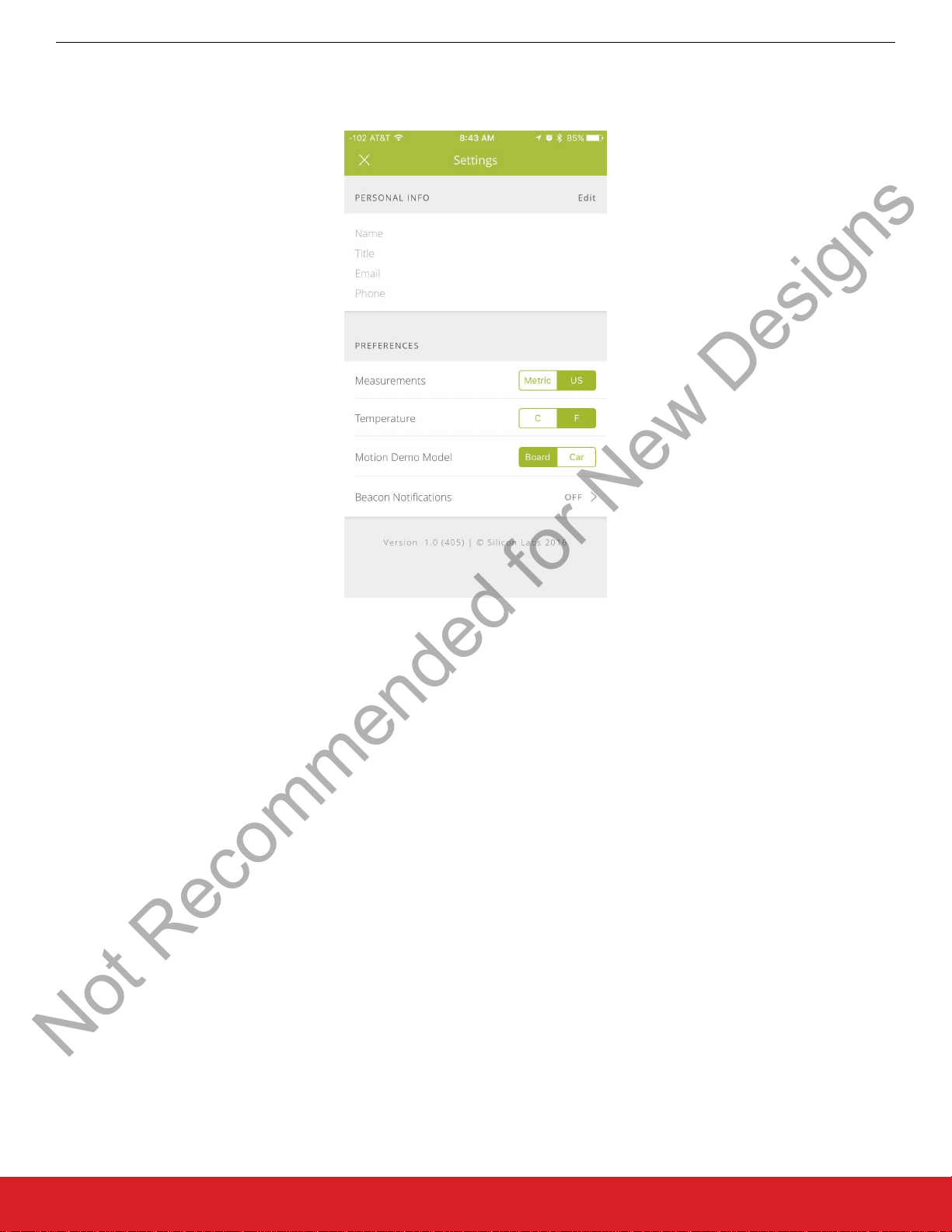
4.4 User App Settings
User-defined settings can be configured in the looking for devices or choose demo screens.
Operation
Figure 4.8. User App Settings
While in this screen, the user can specify their contact information that will then be displayed when sharing links. The user can also
specify desired measurement and temperature units, as well as which 3D model to render in the motion demo (ThunderBoard or ReactCar). The user can also enable beacon notifications that will alert the app when a beaconing Thunderboard React is within the radio’s
signal range and available for connection.
silabs.com | Smart. Connected. Energy-friendly. Rev. 1.3 | 12
Page 14
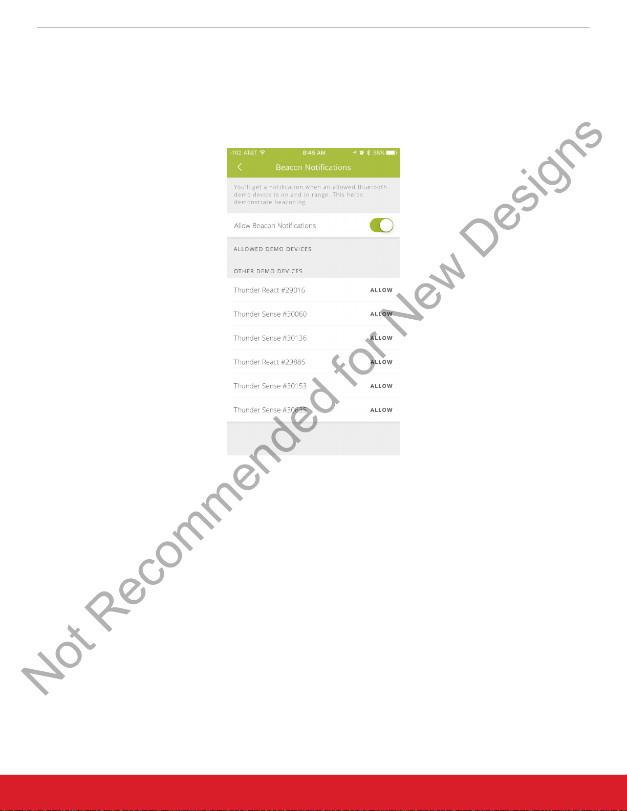
4.5 Configuring Beacon Notifications
Not Recommended for New Designs
UG164: ThunderboardTM React (RD-0057-0201) User's Guide
Operation
Within the User
board React can be allowed to notify the mobile app of its nearby presence and once clicked, the app will automatically pair with the
device and directly open the choose demo screen. To allow or remove a Thunderboard React, click on ALLOW or REMOVE for that
particular device.
Note: To allow a device it must have already been connected to the app.
App Settings, a user can enable/disable beacon notifications. When these notifications are enabled, a known Thunder-
Figure 4.9. Device Beacon Notification Settings
For iOS devices: In iOS, beacon notifications alert a mobile phone that it is within a nearby beacon. As a result, the phone's OS can
sometimes inhibit notifications so as to avoid flooding the mobile phone with continual notifications as it resides on a boundary of a
beacon’s radio signal range. The best method to reliably demonstrate this feature is to have the allowed Thunderboard React device
powered off, power it up, and then press the SW0 or SW1 button. Within seconds, the beacon should trigger a notification and the
dialog box will allow a user to open the mobile app.
For Android devices: As of Android OS version 4.4, beacon notifications with this demonstration only work if the mobile app is launched
and is at least residing in the phone’s background.
silabs.com | Smart. Connected. Energy-friendly. Rev. 1.3 | 13
Page 15
UG164: ThunderboardTM React (RD-0057-0201) User's Guide
Not Recommended for New Designs
Operation
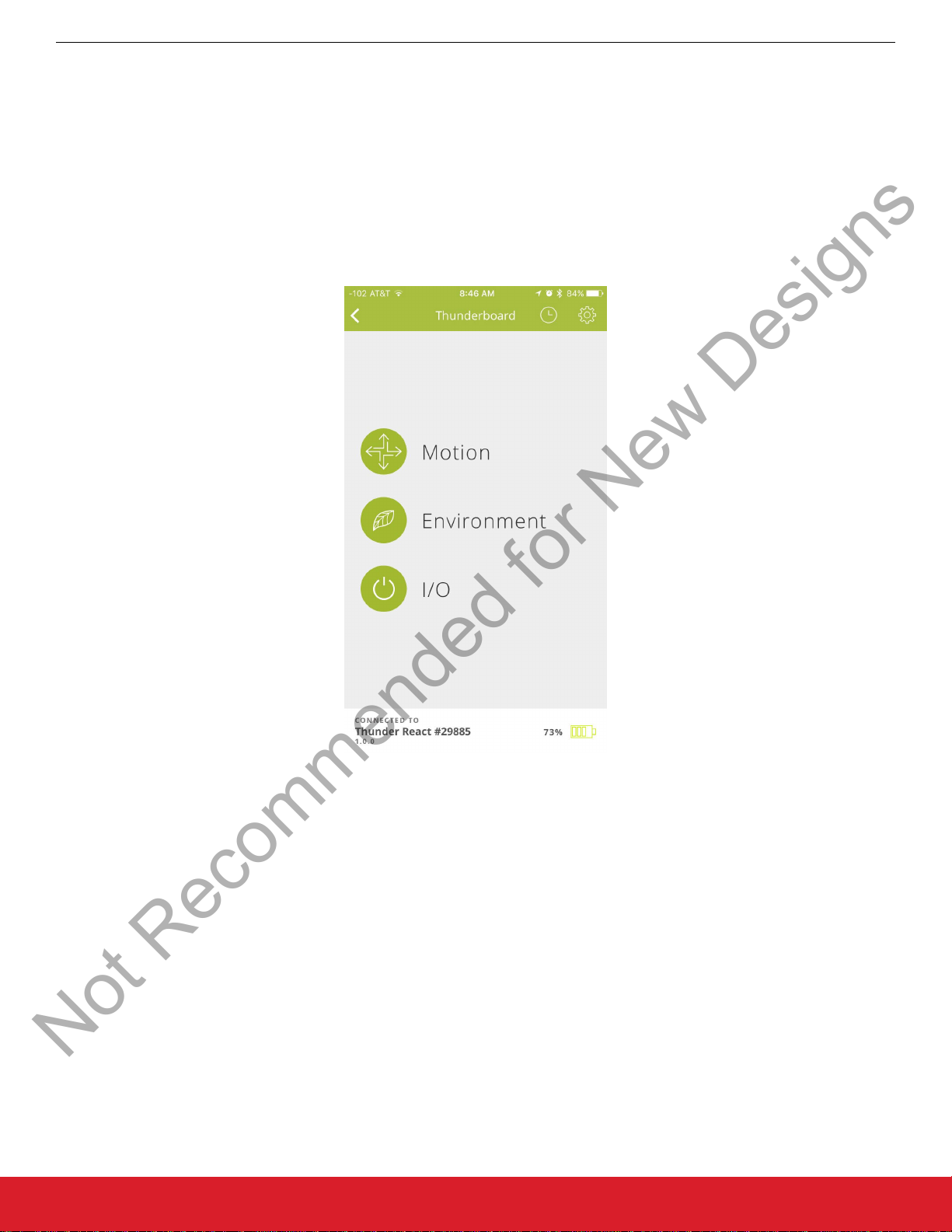
4.6 Select a Demo
Once the mobile app is connected (paired) to a Thunderboard React, it will display the following available demos:
• Motion: Uses the accelerometer, gyroscope, and hall-effect sensors
• Environment: Uses the temperature, relative humidity, ambient, and UV sensors
I/O: Uses the two momentary push buttons and two LEDs
•
The next sub-sections will describe each demo and how to operate them. The subsequent sub-sections will then describe how to
stream each of these demos to the cloud where they can be viewed and shared by multiple device clients. Both live and completed
streamed demo sessions can be viewed by multiple clients for up to 30 days.
To select a specific demo, click on it.
Figure 4.10. Selected Demo Loading Screen
silabs.com | Smart. Connected. Energy-friendly. Rev. 1.3 | 14
Page 16
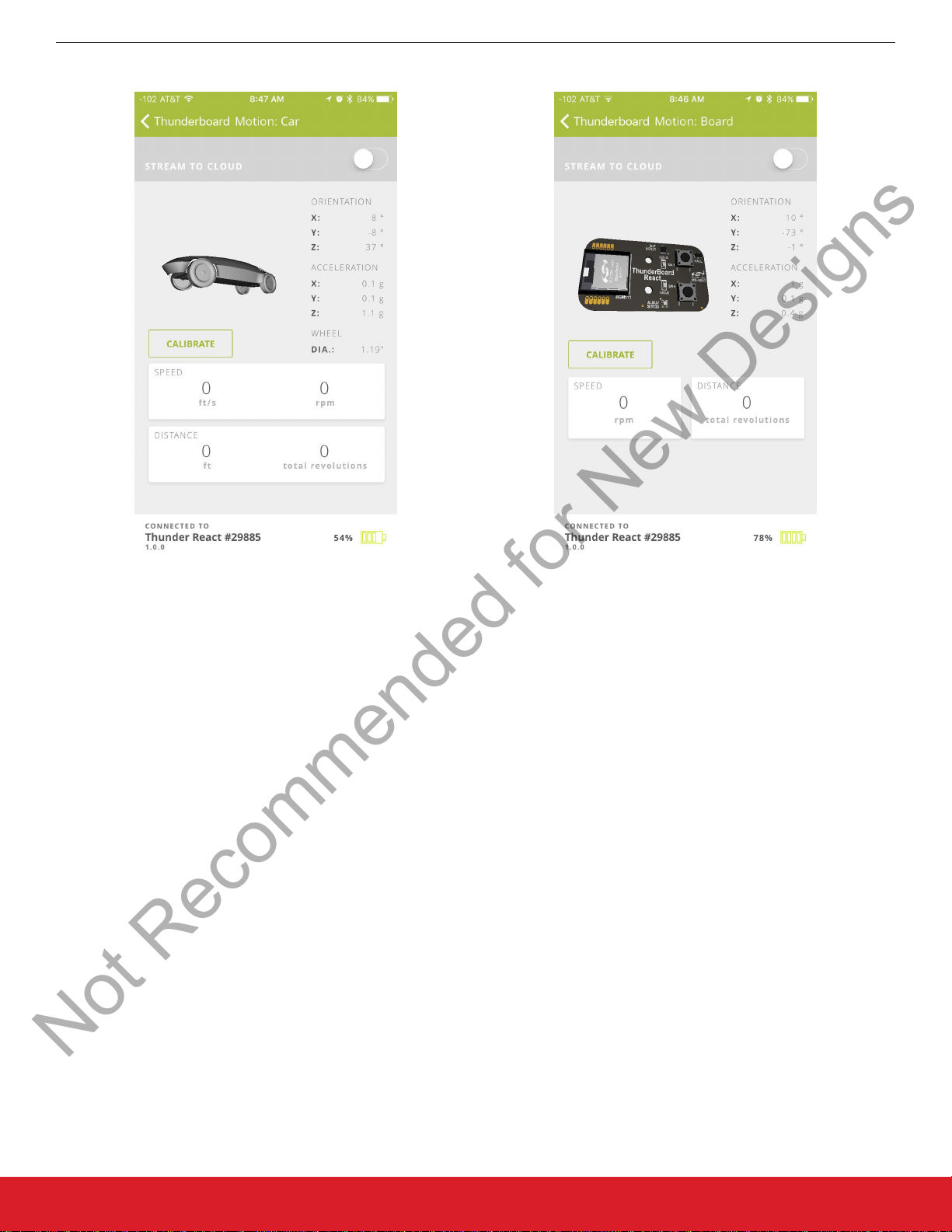
4.6.1 Motion Demo
Not Recommended for New Designs
UG164: ThunderboardTM React (RD-0057-0201) User's Guide
Operation
Figure 4.11. Motion Demo Screens
The motion demo can demonstrate the following:
• 3-axis orientation, shown numerically and visually via a 3D rendered model
• 3-axis acceleration, shown numerically
Speed and distance via the hall-effect sensor’s output displayed as a CSC (Cycling Speed and Cadence) service
•
For the rendered 3D model, either the ThunderBoard or the React Car can be displayed in the demo. To change what is displayed, go
to the device settings and select the desired model, as shown in 4.4 User App Settings.
For orientation and acceleration, the Thunderboard React’s axes can be calibrated. To do so, rest the Thunderboard React in an upright position (top of the device facing up). While leaving the device untouched and not moving, click on “calibrate”. The mobile app will
perform a calibration calculation for a few seconds, displaying a pop-up message while it is doing so until it completes. Once completed, move the Thunderboard React and notice the device is now aligned to the 3D model on the mobile app screen. The specifics of the
device-to-app refresh rate as well as the angle values shown in the app can be found in the firmware section.
For speed and distance, the hall-effect sensor is to be paired with a magnet. The firmware is designed to display this sensor as a CSC
service, which means it will assume every nearby magnetic sensor contact point will be counted as a full wheel revolution. From each
revolution, it will determine a speed and distance based on a specific wheel diameter commonly found in pinewood derby races. For
more information on refresh rates and speed values, refer to 6. Firmware.
silabs.com | Smart. Connected. Energy-friendly. Rev. 1.3 | 15
Page 17
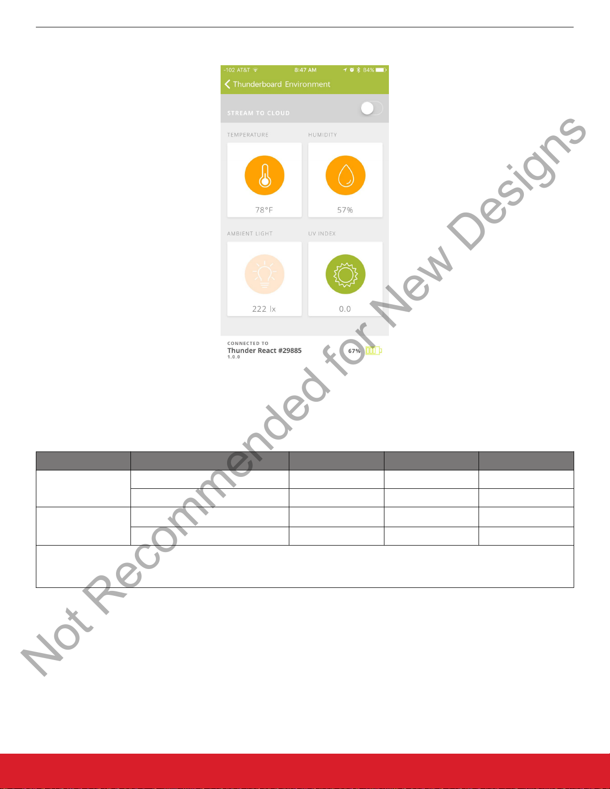
4.6.2 Environment Demo
Not Recommended for New Designs
UG164: ThunderboardTM React (RD-0057-0201) User's Guide
Operation
Figure 4.12. Environment Demo Screen
This demonstration uses the Si1133 and Si7021 to display the following environment sensors (with range).
Table 4.1. Environment Demo Measurements
Sensor Type Min Max Unit
Si1133 Ambient Light 1 99,999 lux
UV Index 1 15 ─
Si7021
Note:
1. Farenheit equivalents can also be displayed via the user app setting.
Temperature
Relative Humidity 0 100 %
1
–40 85 C
silabs.com | Smart. Connected. Energy-friendly. Rev. 1.3 | 16
Page 18
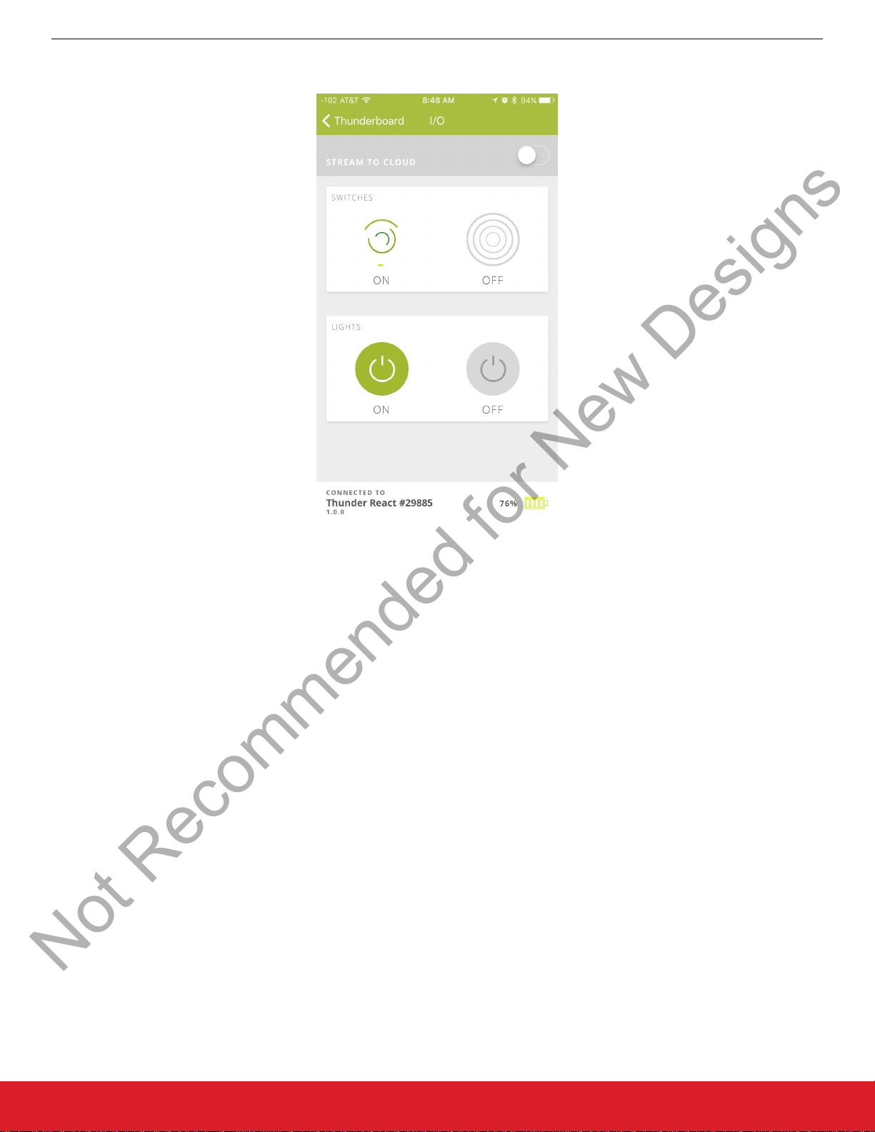
4.6.3 I/O Demo
Not Recommended for New Designs
UG164: ThunderboardTM React (RD-0057-0201) User's Guide
Operation
Figure 4.13. I/O Demo Screen
For a simple demonstration, the mobile app can show how a button press on the device can result in a change on the mobile app
screen, and vice versa. Upon pressing either SW-0 or SW-1, the mobile app will animate the two circle icons along the top area of the
demo screen. Upon pressing either the left or right icons in the lower section of the screen, the blue and green LEDs on Thunderboard
React can be statically illuminated.
silabs.com | Smart. Connected. Energy-friendly. Rev. 1.3 | 17
Page 19

4.7 Stream to the Cloud
Not Recommended for New Designs
UG164: ThunderboardTM React (RD-0057-0201) User's Guide
Operation
While connected to
device clients can view its live stream. The same link will also display the final results of the stream, and will remain available for later
viewing for up to 30 days. All available demos can be streamed to the cloud.
To stream to the cloud while in a demo, move the toggle stream to ON (located along the top right area of the mobile app). The demo’s
results are now being simultaneously transmitted on the app screen and streamed into the cloud. While in this streaming mode, the
session can be shared via a link (see 4.7.1 Send a Link to the Cloud Session), or it can be immediately viewed from the same mobile
device by using its mobile browser and placing the app in the phone’s background (see 4.7.2 View the Cloud Session).
Thunderboard React, the mobile app can simultaneously stream the live demo session to the cloud where multiple
Figure 4.14. Stream to Cloud Enabled
silabs.com | Smart. Connected. Energy-friendly. Rev. 1.3 | 18
Page 20

4.7.1 Send a Link to the Cloud Session
Not Recommended for New Designs
UG164: ThunderboardTM React (RD-0057-0201) User's Guide
Operation
Once a cloud
the same mobile device. To do any of these options, select the share icon along the top right of the app screen (the share icon looks
like an up arrow out of an open box). Upon selecting, the mobile app will display a pop-up window with various available options.
stream session is enabled, the user has the ability to share the stream to others and view the session from the cloud on
Figure 4.15. Sharing the Cloud Session
To share the link, select from a multitude of sharing options (e.g., Email, Twitter, Facebook). For this document, the SMS message and
the email link will be described.
To share via email in iOS, select the email client and a draft email will appear. Add a recipient(s), edit the draft email as needed, and
send the email. On completion, the phone will return the user to the mobile app.
silabs.com | Smart. Connected. Energy-friendly. Rev. 1.3 | 19
Page 21

UG164: ThunderboardTM React (RD-0057-0201) User's Guide
Not Recommended for New Designs
Operation
Figure 4.16. Sharing the Cloud Session via Email
To share via SMS message in iOS, select the message client and a draft message will appear. Add a recipient(s), edit the draft as
needed, and send the message. Upon completion, the phone will return the user to the mobile app.
Figure 4.17. Sharing the Cloud Session via Message
silabs.com | Smart. Connected. Energy-friendly. Rev. 1.3 | 20
Page 22

4.7.2 View the Cloud Session
Not Recommended for New Designs
UG164: ThunderboardTM React (RD-0057-0201) User's Guide
Operation
While in the
session directly from the cloud. If connected to the internet, the screen will now display a mobile view of the cloud streaming session.
While in this mode the app will move to the background and maintain the connections to the connected Thunderboard React device and
the cloud database in the internet. The cloud database is a responsible web design and will render the session based on the screen’s
size. For live streams, the cloud view will show the last 30 seconds of collected data. Once a live stream ends, the same link will display
the entire stream session in a summary format.
mobile phone with the app streaming to the cloud, open the share icon and select the mobile browser to view the live
silabs.com | Smart. Connected. Energy-friendly. Rev. 1.3 | 21
Page 23

UG164: ThunderboardTM React (RD-0057-0201) User's Guide
Not Recommended for New Designs
Operation
Figure 4.18. Mobile Version of the Viewed Live Cloud Session
silabs.com | Smart. Connected. Energy-friendly. Rev. 1.3 | 22
Page 24

4.7.3 View from Another Client
Not Recommended for New Designs
UG164: ThunderboardTM React (RD-0057-0201) User's Guide
Operation
While viewing the
React platform, one of the innovative features of this demo is its ability to support multiple clients from its cloud database using
Firebase.
To view from another device client, this client should be sent a shared link. The other device(s) can then click on the link and open up a
separate, synchronized view from the cloud database.
cloud session from the same mobile client is a great way to demonstrate the cloud-connectivity of the Thunderboard
Figure 4.19. Large Screen Viewing of a Live Cloud Session
silabs.com | Smart. Connected. Energy-friendly. Rev. 1.3 | 23
Page 25

4.7.4 View Past Sessions
Not Recommended for New Designs
UG164: ThunderboardTM React (RD-0057-0201) User's Guide
Operation
Each device’s last
Sessions” in the lower center section of the screen. These past sessions will be available for 30 days from the end of their session time.
ten sessions that have been shared to the cloud can be viewed from the cloud screen. To do so, click on “Past
Figure 4.20. Past Sessions
silabs.com | Smart. Connected. Energy-friendly. Rev. 1.3 | 24
Page 26

UG164: ThunderboardTM React (RD-0057-0201) User's Guide
Not Recommended for New Designs
5. Hardware
This section describes the key aspects of the Thunderboard React hardware design.
mini-simplicity
connector
Hardware
Si7021
Relative
Humidity
& Temperature
Sensor
Si1133
Ambient Light &
UV Sensor
I2C
I2C
I2C
BGM111
Bluetooth Smart
module with
chip antenna
and
Cortex M4 CPU
Figure 5.1. Hardware Block Diagram
MPU-6500
6-axis
accelerometer
& gyroscope
Si7201
hall-effect
sensor
LED-B
LED-G
SW-0
SW-1
Figure 5.2. ThunderBoard Printed Circuit Board (Front & Back)
silabs.com | Smart. Connected. Energy-friendly. Rev. 1.3 | 25
Page 27

5.1 Mini-Simplicity Debug Connector
Not Recommended for New Designs
UG164: ThunderboardTM React (RD-0057-0201) User's Guide
Hardware
The Thunderboard React
firmware application with the hardware. For more information on the firmware application, refer to 6. Firmware.
includes a 10-pin mini-simplicity debug connector (J3) to allow a user to develop, program, and debug the
Figure 5.3. J3 Mini-Simplicity Debug Connector
Table 5.1. Mini-Simplicity Debug Connector Pin Assignments
Pin Name
1 VAEM
2 GND
3 RST
4 VCOM_RX
5 VCOM_TX
6 SWO
7 SWDIO
8 SWCLK
9 PTI_FRAME
10 PTI_DATA
Note:
1.
The connector on the hardware is a keyed male 10-pin 0.050” (1.27 mm), 2×5 array.
silabs.com | Smart. Connected. Energy-friendly. Rev. 1.3 | 26
Page 28

5.2 User-accessible Pads
Not Recommended for New Designs
UG164: ThunderboardTM React (RD-0057-0201) User's Guide
Hardware
For further design
cuitry. These can be found bordering the BGM111 footprint, and are labeled along the bottom of the printed circuit board.
modifications, the hardware also includes solder pads that can be used to interact with the design with external cir-
Figure 5.4. User-accessible Pad Arrays
Table 5.2. User-accessible Pad Pin Assignments
Schematic Pins BGM111 Pins Schematic Signals
TP16 PD13 —
TP17 PD14 —
TP18 PD15 —
TP19 PA2 LED-B
TP21 PA3 SW0
TP22 PA5 —
TP23 PF7 SW1
TP24 PF6 LED-G
TP25 VMCU PWR
TP26 GND GND
TP27 VMCU PWR
TP28 GND GND
Note:
1.
Additional test points found along the printed circuit board: PF3, PF4, PF5, SCL, SDA, VBAT, GND.
silabs.com | Smart. Connected. Energy-friendly. Rev. 1.3 | 27
Page 29

UG164: ThunderboardTM React (RD-0057-0201) User's Guide
Not Recommended for New Designs
Firmware
6. Firmware
This section describes the ThunderBoard-React application firmware.
6.1 Obtaining the Firmware Application
The firmware for the ThunderBoard-React can be found within the Silicon Labs Bluetooth Smart SDK as a sample application. This
sample application is provided as both a pre-compiled binary and as a source project that can be opened can be opened and built with
Simplicity Studio.
6.2 Tools Needed for Firmware Modification
The following additional hardware and software is needed to modify the firmware application on the ThunderBoard-React evaluation
board:
Hardware Tools:
• Wireless STK with supplied USB-to-mini-USB cable
• SLSDA001A adapter (includes 10-pin ribbon cable).
Software Tools:
• Simplicity Studio v4 or later with latest Wireless Products package and the Bluetooth Smart SDK v2.0.0 software stack or later installed
• IAR Embedded Workbench for ARM 7.60 or later
silabs.com | Smart. Connected. Energy-friendly. Rev. 1.3 | 28
Page 30

6.3 Simplicity Studio Tool Setup
Not Recommended for New Designs
UG164: ThunderboardTM React (RD-0057-0201) User's Guide
Firmware
To ensure Simplicity
the upper left corner:
Click the Basic Installer button and go to the Select By Product Group tab. Make sure the Wireless Products box is checked and click
Next.
Studio has the latest wireless packages and Bluetooth Smart SDK installed, click on the Update Software icon in
Figure 6.1. Update Software Icon
Figure 6.2. Verify Wireless Product Installation
silabs.com | Smart. Connected. Energy-friendly. Rev. 1.3 | 29
Page 31

Make sure the Bluetooth Smart SDK box is checked and click Finish.
Not Recommended for New Designs
UG164: ThunderboardTM React (RD-0057-0201) User's Guide
Firmware
Figure 6.3. Verify Bluetooth Smart SDK Installation
The IAR ARM compiler is used to compile the ThunderBoard-React sample application. The compiler is included in IAR Embedded
Workbench for ARM (EWARM), which needs to be installed. To point Simplicity Studio to your IAR installation, go to Settings (Green
cog wheel in upper left hand corner of the Launcher perspective). Then navigate to IAR Embedded Workbench and set the Path to the
IAR Embedded Workbench IDE installation directory.
silabs.com | Smart. Connected. Energy-friendly. Rev. 1.3 | 30
Page 32

UG164: ThunderboardTM React (RD-0057-0201) User's Guide
Not Recommended for New Designs
Firmware
Figure 6.4. IAR Embedded Workbench Path
silabs.com | Smart. Connected. Energy-friendly. Rev. 1.3 | 31
Page 33

UG164: ThunderboardTM React (RD-0057-0201) User's Guide
Not Recommended for New Designs
6.4 Open ThunderBoard-React Project in Simplicity IDE
In the Simplicity Studio Launcher screen, select the Solutions tab on the left-hand side and click the Add Devices button.
Figure 6.5. Add Devices
In the Add Devices box, search for the ThunderBoard React RD-0057-0201 kit, select it, and click OK.
Firmware
Figure 6.6. Add ThunderBoard-React
Once the ThunderBoard-React kit is added and selected, you should see all available resources—like Documentation, Compatible
Tools, etc.—in the Simplicity Studio main screen.
silabs.com | Smart. Connected. Energy-friendly. Rev. 1.3 | 32
Page 34

UG164: ThunderboardTM React (RD-0057-0201) User's Guide
Not Recommended for New Designs
Firmware
Click the New Project button.
act sample application and click Next.
Select the Silicon Labs Bluetooth Smart Framework and click Next. Select the SOC – ThunderBoard Re-
Figure 6.7. ThunderBoard-React Resources
silabs.com | Smart. Connected. Energy-friendly. Rev. 1.3 | 33
Page 35

UG164: ThunderboardTM React (RD-0057-0201) User's Guide
Not Recommended for New Designs
Firmware
Figure 6.8. Select ThunderBoard-React Sample Application
Select a suitable name for your project and click Next. In the Project Setup screen, make sure ThunderBoard-React is selected in the
Board section. Once this is done, the Part section should be automatically set to EFR32BG1B232F256GM48. Then click Finish.
silabs.com | Smart. Connected. Energy-friendly. Rev. 1.3 | 34
Page 36

UG164: ThunderboardTM React (RD-0057-0201) User's Guide
Not Recommended for New Designs
Firmware
Figure 6.9. Project Setup with IAR ARM
Simplicity Studio will then create a project and open it in the Simplicity IDE and Configurator. In the soc-thunderboard-react.isc tab, click
Generate to fully populate the project with the appropriate files and settings. Click OK to overwrite any files when prompted.
silabs.com | Smart. Connected. Energy-friendly. Rev. 1.3 | 35
Page 37

UG164: ThunderboardTM React (RD-0057-0201) User's Guide
Not Recommended for New Designs
Firmware
Figure 6.10. Project Generation
Once the project is generated, it can be built by going to Project->Build Project
.
silabs.com | Smart. Connected. Energy-friendly. Rev. 1.3 | 36
Page 38

6.5 Program Thunderboard React
Not Recommended for New Designs
UG164: ThunderboardTM React (RD-0057-0201) User's Guide
Firmware
In order to
(SLSDA001A), and a10-pin ribbon cable (supplied with SLSDA001A).
Follow these steps to connect the Wireless STK as a debugger to the Thunderboard React, as shown in the picture above:
1. Remove the radio module plugin on the Wireless Starter Kit.
2. Attach 10-pin adapter board (SLSDA001A) to the two male 20-pin connectors on the Wireless STK.
3.
4. Connect the other end of the 10-pin ribbon cable to the 10-pin Mini Simplicity connector on the ThunderBoard-React
5. Connect the Wireless STK to the platform running Simplicity Studio via either USB or Ethernet.
6. Make sure the power switch on the bottom of the Wireless STK is in the rightmost position, marked AEM.
7. Make sure the power switch on the ThunderBoard React is in the Vext position (away from the battery holder).
program ThunderBoard-React, you need an external debugger/programmer, like a Wireless Starter Kit, a 10-pin adapter
Figure 6.11. Connect Simplicity Studio to a Thunderboard React via Wireless STK
Connect the 10-pin ribbon cable to the middle 10-pin connector, marked MINI. The key tap on the ribbon cable connector should
be pointing down.
In Simplicity Studio return to the main perspective, and left-click on the connected J-link device from the Device list on the left and click
on Device Configuration… from the menu that appears.
Figure 6.12. Device Configuration
In the Configuration menu that appears, go to the Adapter Configuration tab and set Debug Mode to OUT.
silabs.com | Smart. Connected. Energy-friendly. Rev. 1.3 | 37
Page 39

UG164: ThunderboardTM React (RD-0057-0201) User's Guide
Not Recommended for New Designs
Firmware
Figure 6.13. Setting Debug Mode
In the Device hardware tab, set the Target part to EFR32BG1B232F256GM48 and set the Boards selection to ThunderBoard React
(RD-005701 Rev01). This will ensure Simplicity Studio is set to communicate with ThunderBoard-React through the external adapter
interface.
silabs.com | Smart. Connected. Energy-friendly. Rev. 1.3 | 38
Page 40

UG164: ThunderboardTM React (RD-0057-0201) User's Guide
Not Recommended for New Designs
Firmware
Figure 6.14. Set Correct Target Part
Once the Debug connection is set up, you can choose to program the ThunderBoard-React with a pre-compiled binary from the Bluetooth Smart SDK or start a debug session from a ThunderBoard React Sensors Demo project in the Simplicity IDE (Press F11 in Simplicity IDE with ThunderBoard React project active).
To program a pre-compiled demo, select the ThunderBoard React RD-0057-0201 from the Solutions tab on the left-hand side of the
main perspective where we added it earlier. Click on Getting Started in the main window, and click on the SOC – ThunderBoard React
box in the Demos list below. In the Demos box that appears, you can select Mode to run with or without the Energy Profiler, and click
Start. When asked to select the kit to run the demo, select the J-Link device that you configured for Debug=OUT earlier. Click OK and
the demo should be programmed to the ThunderBoard-React.
silabs.com | Smart. Connected. Energy-friendly. Rev. 1.3 | 39
Page 41

UG164: ThunderboardTM React (RD-0057-0201) User's Guide
Not Recommended for New Designs
Firmware
Figure 6.15. Program ThunderBoard React Sample Application
You have successfully programmed a ThunderBoard-React! Note that in some cases when performing this step, the ThunderBoardReact’s Si1133 power supply will drop and cause the board to flash both Blue and Green LEDs. If this occurs, remove both the cable
and the coin-cell battery, and let the ThunderBoard-React sit without power for at least ten minutes. This will clear the Si1133’s low
supply detection circuitry.
silabs.com | Smart. Connected. Energy-friendly. Rev. 1.3 | 40
Page 42

UG164: ThunderboardTM React (RD-0057-0201) User's Guide
Not Recommended for New Designs
6.6 Sensor and IO Firmware Handling
The following sensor data is obtained by the BMG111 module and made available via the Bluetooth Smart connection:
• 3-axis accelerometer
• 3-axis gyroscope
Relative humidity
•
• Temperature
• Ambient Light
• UV index
• Battery level
• Hall-effect detection
Firmware
silabs.com | Smart. Connected. Energy-friendly. Rev. 1.3 | 41
Page 43

6.6.1 Accelerometer and Gyroscope
Not Recommended for New Designs
UG164: ThunderboardTM React (RD-0057-0201) User's Guide
Firmware
The accelerometer and
of the board is divided into three axes: X, Y, and Z, as shown in the figure below.
gyroscope in the MPU-6500 is used to present acceleration and orientation of the sensor board. The orientation
Figure 6.16. Hardware Axis Orientation
To minimize offset in the gyroscope data, the firmware supports a calibration (reset orientation) command. When a calibration is started, the sensor board must be left stationary until the calibration is complete. LED-G will be lit as long as the calibration is ongoing.
When the calibration
equal to the hardware’s actual X, Y, and Z positioning. After calibration successfully completes, any change in orientation after the orientation reset will be represented in the angle difference between X, Y, and Z and x, y, and z, according to the figure below. The angles
presented are Alpha (α), Beta (β), and Gamma (γ).
(reset orientation) command is issued, a reference coordinate system (x, y, z in the figure below) is defined to be
Figure 6.17. Orientation Representation
silabs.com | Smart. Connected. Energy-friendly. Rev. 1.3 | 42
Page 44

UG164: ThunderboardTM React (RD-0057-0201) User's Guide
Not Recommended for New Designs
Firmware
The accelerometers and gyroscope sensors are sampled at 200 Hz by the firmware and the sensor data is used to calculate acceleration and orientation, which can be sent as GATT notifications at 5 Hz.
Note that these
accelerometers has a measurement range of ±16 g and the gyroscopes can detect maximum ±2000 deg/s. If the user rotates the device quickly or drops it on a table, the sensors will most likely enter an overflow situation. There is no indication that an overflow has
occurred.
Normally, the accelerometers are used to calculate the acceleration and the gyroscopes are used to calculate orientation. However, the
combination of accelerometers and gyroscopes makes it possible to zero out drift in the x and y-axis orientations as long as the x and yaxis are within ±80° or the x-axis is within 180 ±80° of the horizontal plane. In this case, the calculated orientation for the x and y-axis
will converge towards the angles calculated from the accelerometers with a time constant of approximately five seconds. There are no
adjustments for the z-axis orientation. Consequently, the calibration will reset the z-angle but not the x and y-angles. The X and Y-axis
is always pointing along the horizontal plane.
There are different rotations that can put the device in a given orientation. However, the convention to bring the device back to its reference where x, y, and z are zero is to first rotate z degrees in the Z-axis, then y degrees in the Y-axis and finally x degrees in the X-axis.
Because of this convention, the x and z-axis will have a range of ±180° and the y-axis has a range of ±90°.
A few examples can illustrate this. All rotations are done “clockwise”, which is at increasing angles when started at zero. All examples
should start at an orientation approximately zero degrees in all three axes.
Rotate the device 360° around the X-axis: During rotation, the x orientation will increase from 0 to 180° when the device is upside
down. Then the x orientation will “jump” from 180 to –179 and continue to increase up to 0 when it is back in the start orientation.
Rotate the device 360° around the Y-axis: During rotation, the y orientation will increase from 0 to 90° when pointing downwards. Rotating it further will make the x-axis to “flip” from 0 to 180° indicating that the device is upside down and “flip” the z-axis from 0 to 180
indicating that it is pointing in the opposite direction relative to start. Rotating it further from pointing down to pointing up will decrease
the y orientation from 90 to –90°. At the top, the x and z orientation will again “flip” back to 0 and the y orientation will increase from –90
to 0. Note that when the device is upside down, the x orientation can easily “flip” between 180 and –179° for small rotations in the Xaxis.
sensors have measurement limitations, and exposing them to excessive inputs will cause measurement errors. The
Rotate the device 360° around the Z-axis: During rotation, the z x orientation will increase from 0 to 180°. Then the z orientation will
jump from 180 to –179 and continue to decrease down to 0 when it is back in the start position.
6.6.2 Environment Sensors
The Si7021 measures both relative humidity and temperature, whereas the Si1133 measures ambient light and UV index. The sensors
are measured when a read command is received and the measurement data is included in the read response.
6.6.3 Battery Level
The battery level is sensed by the BGM111 as it measures the supply voltage level and translates this into a percentage of remaining
charge using a look-up table specific for a given CR2032 battery. The battery level is measured every ten seconds.
6.6.4 Hall-effect Sensor
The hall-effect sensor is used to count wheel revolutions by detecting nearby magnetic fields beyond a threshold and will increment a
revolution counter every time the sensor outputs a rising edge. The GATT client is notified of the updated revolution count at a 5 Hz rate
through the CSC service.
silabs.com | Smart. Connected. Energy-friendly. Rev. 1.3 | 43
Page 45

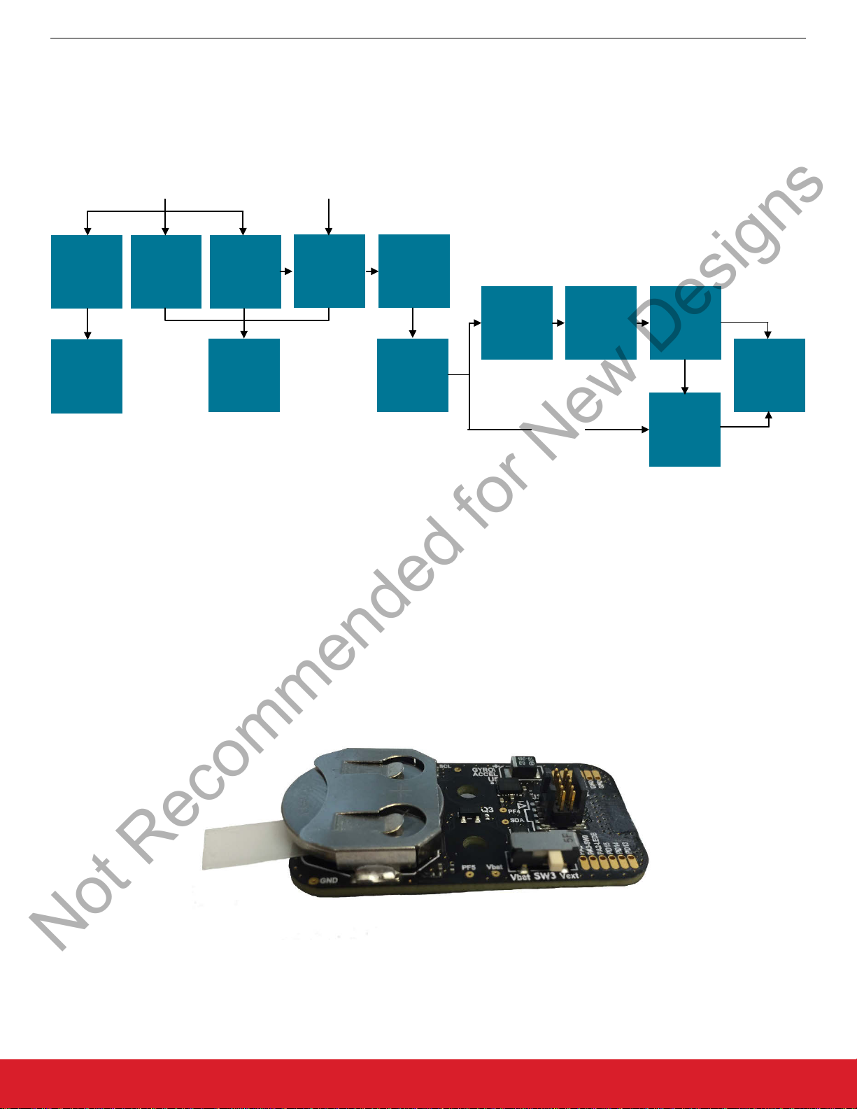
6.7 Firmware Operation
Not Recommended for New Designs
The firmware operates as a Bluetooth Smart peripheral and has five main states.
UG164: ThunderboardTM React (RD-0057-0201) User's Guide
Firmware
Any button
pushed
SLEEP CONNECTED
30 second
timeout
OK
Reset
6.7.1 Self-test State
After the device
ware failures. If the test is OK, the device transitions to the Sleep state. If a failure is found, the device enters the Error state.
6.7.2 Error State
If an error is found, the device stays in the Error state until the device is reset by removing and re-installing the battery. While in this
state, the blue LED (LED-B) and green LED (LED-G) will blink in an alternating pattern.
wakes up from Reset, it performs a Self-test to check that all sensors are can be accessed and that there are no hard-
SELF TEST ERROR
Figure 6.18. Firmware Application State Diagram
Not OK
ADVERTISEMENT
BEACONING
Connection
opened
Connection
closed
6.7.3 Sleep State
In this state the Bluetooth Smart stack is not operational, all sensors are put in their lowest power state and the BGM111 is put in a
Deep Sleep state (EM2). The current consumption in this state is around 10 µA. While in this state, both the blue and green LEDs are
extinguished.
6.7.4 Advertisement State
In this state, the Bluetooth Smart stack is in Advertising mode using the data found in Table 6.1 Beacon Advertisement Data on page
45. All sensors are put in their lowest power state and the BGM111 is in Sleep (EM1) between each advertisement transmission. If a
connection is made to a central device, the advertisement is stopped and the device enters the Connected state. If no connection is
made within 30 seconds, the device goes back to the Deep Sleep state. While in Deep Sleep state, the blue LED (LED-B) is blinking
once a second and the green LED (LED-G) is off.
6.7.5 Connected State
This state is entered once a device is connected to a central device. In this state, the device acts as a GATT server and all sensors are
configured to their respective operational states. The BGM111 is in Sleep (EM1) when not handling the stack or the sensors.
• The green LED (LED-G) blinks once when a connection is opened.
• Both LEDs can be set/cleared by the central device (GATT client) through the Bluetooth Smart connection (Automation IO service).
6.8 Bluetooth Smart Over-the-air Definition
This section describes the over-the-air interface between the phone application and the Thunderboard React including advertisement
data, scan response, and GATT services and characteristics.
6.8.1 Advertisement
The EFR32 Blue Gecko alternates between two advertisement payloads every second. One payload is an iBeacon payload and the
other is a regular non-beacon payload containing the local name and a manufacturing-specific firmware ID.
silabs.com | Smart. Connected. Energy-friendly. Rev. 1.3 | 44
Page 46

6.8.2 iBeacon Advertisement Payload
Not Recommended for New Designs
UG164: ThunderboardTM React (RD-0057-0201) User's Guide
Firmware
Below is the
format and advertises on all advertisement channels.
advertisement payload sent out by the BGM111 in an uni-directed connectable mode. It implements an Apple iBeacon
Table 6.1. Beacon Advertisement Data
Type Value Description
UINT8 0x02 FLAGS_LENGTH
UINT8 0x01 FLAGS_TYPE
UINT8 0x05 FLAGS_BREDR_NOT_SUPPORTED
FLAGS_LIMITED_DISCOVERABLE
UINT8 0x1A MANDATA_LENGTH
UINT8 0xFF MANDATA_TYPE
UINT16 0x004C MANDATA_BEACON_COMPANYID
UINT16 0x1502 MANDATA_BEACON_TYPE
UINT128 0xCEF797DA-2E91-4EA4-A424-F45082AC0682 MANDATA_BEACON_UUID
UINT16 0x00nn MANDATA_BEACON_MAJOR
UINT16 0xnnnn MANDATA_BEACON_MINOR
UINT8 0xC3 MANDATA_BEACON_RSSI
The major and minor values of the beacon payload together constitute a 24-bit ID that is unique to an individual ThunderBoard device.
The two Least
Least Significant Octet of the major value. The unique ID is equal to the #nnnnnnnn decimal value given in the Device Name in the
table above. The unique ID is also equal to the three Least Significant Octets of the Manufacturer Identifier in 6.9.3 Device Information
Service (0x180A).
Significant Octets of the unique ID equals the 16-bit minor value. The Most Significant Octet of the unique ID equals the
silabs.com | Smart. Connected. Energy-friendly. Rev. 1.3 | 45
Page 47

UG164: ThunderboardTM React (RD-0057-0201) User's Guide
Not Recommended for New Designs
6.8.3 Non-beacon Advertisement Payload
Below is the non-beacon advertisement payload sent by the BGM111 on all advertisement channels.
Table 6.2. Non-beacon Advertisement Payload
Type Value Description
UINT8 0x02 FLAGS_LENGTH
UINT8 0x01 FLAGS_TYPE
UINT8 0x05 FLAGS_BREDR_NOT_SUPPORTED
FLAGS_LIMITED_DISCOVERABLE
UINT8 0x06 MANDATA_LEN
UINT8 0xFF MANDATA_TYPE
UINT16 0x0047 MANDATA_COMPANY_ID
UINT16 0x0001 MANDATA_FIRMWARE_ID
UINT8 Length of local name +1 LOCALNAME_LENGTH
Firmware
UINT8 0x09 LOCALNAME_TYPE
UINT8[n] Local name LOCALNAME
The MANDATA_FIRMWARE_IDE field can be used to uniquely identify the capabilities of the board firmware.
Local name is
changed accordingly.
6.9 GATT Description
6.9.1 Generic Access Service (0x1800)
Characteristic UUID
Device Name 0x2a00 UFT8S
Appearance 0x2a01 0:1 UINT16
the same as “Device Name” in the Generic Access Service. If the “Device Name” is changed, the Local name will be
Table 6.3. Characteristics included in Generic Access Service
Interpretation
Properties Descriptors
Byte Encoding
Read Write
“Thunder React #nnnnn”
nnnnn is a 5-decimal digit serial
Read
1
0: Unknown
Note:
1. The Device name can be written by a GATT client, but the length of the name written is limited to 20 characters.
silabs.com | Smart. Connected. Energy-friendly. Rev. 1.3 | 46
Page 48

UG164: ThunderboardTM React (RD-0057-0201) User's Guide
Not Recommended for New Designs
6.9.2 Generic Attribute Service (0x1801)
Table 6.4. Characteristics Included in Generic Attribute Service
Characteristic UUID Interpretation Properties Descriptors
Byte Encoding
Firmware
Service Changed 0x2a05 0:1 UINT16
Start of affected attribute handle range
2:3 UINT16
End of affected attribute handle range
The Service Changed Attribute is included to avoid caching of the device name in iOS devices.
6.9.3 Device Information Service (0x180A)
Table 6.5. Characteristics included in Device Information Service
Characteristic UUID
Manufacturer Name
String
Model Number
String
Hardware Revision
String
Byte Encoding
0x2a29 UFT8S
0x2a24 UTF8S
0x2a27 UTF8S
Interpretation
“Silicon Labs”
“RD-0057”
4 digit string
Indicate
Properties Descriptors
Read
Read
Read
Firmware Revision
String
System ID 0x2a23 0:4 UINT40
6.9.4 Battery Service (0x180f)
Characteristic UUID
Battery Level 0x2a19 0 UINT8: Battery level in % Read Notify Client Characteristic
0x2a26 UTF8S
X.Y.Z revision format
Manufacturer Identifier
5:7 UINT24
Organizationally Unique Identifier
Table 6.6. Characteristics included in Battery Service
Interpretation
Byte Encoding
Read
Read
Properties Descriptors
Configuration
silabs.com | Smart. Connected. Energy-friendly. Rev. 1.3 | 47
Page 49

6.9.5 Environmental Sensing Service (0x181a)
Not Recommended for New Designs
Table 6.7. Characteristics included in Environmental Sensing Service
UG164: ThunderboardTM React (RD-0057-0201) User's Guide
Firmware
Characteristic UUID
Humidity 0x2a6f 0:1 UINT16
Temperature 0x2a6e 0:1 INT16
UV Index 0x2a76 0 UINT8
6.9.6 Ambient Light Service (0xd24c4f4e-17a7-4548-852c-abf51127368b)
Characteristic UUID
Ambient Light 0xc8546913-
bfd9-45eb-8dde-9f8
754f4a32e
Byte Encoding
Table 6.8. Characteristics included in Ambient Light Service
Byte Encoding
0:3 UINT32
Interpretation
Unit in % with resolution of 0.01 %
Units in °C with resolution of 0.01 °C
Unit-less
Interpretation
Lux with resolution of 0.01 lux
Properties Descriptors
Read
Read
Read
Properties Descriptors
Read
silabs.com | Smart. Connected. Energy-friendly. Rev. 1.3 | 48
Page 50

6.9.7 Cycling Speed and Cadence Service (0x1816)
Not Recommended for New Designs
Table 6.9. Characteristics included in Cycling Speed and Cadence Service
UG164: ThunderboardTM React (RD-0057-0201) User's Guide
Firmware
Characteristic UUID
Interpretation
Byte Encoding
CSC Measurement 0x2a5b 0 Bit 0: Wheel Revolution Data Present
(1 = True)
1:4 UINT32
Cumulative Wheel Revolutions
5:6 UINT16: Last Wheel Event Time given
with a resolution of 1/1024 s.
CSC Feature 0x2a5c 0:1 Bit 0: Wheel Revolution Data Supported
(1 = True)
SC Control Point 0x2a55 0 UINT8
Op Code
0x01: Set Cumulative Value
1:4 UINT32
Cumulative Value
5 UINT8
Properties Descriptors
Notify Client Characteristic
Configuration
Read
Write
Indicate
Client Characteristic
Configuration
Request Op Code
0x01: Set Cumulative Value
6 UINT8
Response Value
0x01: Success
0x02: Not supported
0x03: Invalid parameter
0x04: Operation Failed
silabs.com | Smart. Connected. Energy-friendly. Rev. 1.3 | 49
Page 51

UG164: ThunderboardTM React (RD-0057-0201) User's Guide
Not Recommended for New Designs
6.9.8 Acceleration and Orientation Service (0xa4e649f4-4be5-11e5-885d-feff819cdc9f)
Table 6.10. Characteristics included in Acceleration and Orientation Service
Firmware
Characteristic UUID
Acceleration
Measurement
Orientation
Measurement
Control Point 0x71e30b8c-4131-
0xc4c1f6e2-4be5-1
1e5-885d-
feff819cdc9f
0xb7c4b694-
bee3-45dd-ba9f-
f3b5e994f49a
4703-b0a0-
b0bbba75856b
Interpretation
Byte Encoding
0:1 INT16: Acceleration along X-axis.
Units in g with resolution of 0.001 g
2:3 INT16: Acceleration along Y-axis.
Units in g with resolution of 0.001 g
4:5 INT16: Acceleration along Z-axis.
Units in g with resolution of 0.001 g
0:1 INT16: Orientation alpha angle in
deg (+180 to –180) with resolution
of 0.01°
2:3 INT16: Orientation beta angle in
deg (+90 to –90) with resolution of
0.01°
4:5 INT16: Orientation gamma angle in
deg (+180 to –180) with resolution
of 0.01°
0 UINT8
Op Code
0x01: Start calibration
Properties Descriptors
Notify Client Characteristic
Configuration
Notify Client Characteristic
Configuration
Write
Indicate
Client Characteristic
Configuration
0x02: Reset orientation
0x10: Response Code
1 UINT8
Request Op Code
Only used in response
2 UINT8
Response Value
0x01: Success
0x02: Error
silabs.com | Smart. Connected. Energy-friendly. Rev. 1.3 | 50
Page 52

6.9.9 Automation IO Service (0x1815)
Not Recommended for New Designs
Table 6.11. Characteristics Included in Automation IO Service
UG164: ThunderboardTM React (RD-0057-0201) User's Guide
Firmware
Characteristic UUID
Digital
(Input or output type
can be read from the
Characteristic Presen-
tation Format descrip-
tor.)
Digital
(Input or output type
can be read from the
Characteristic Presen-
tation Format descrip-
tor.)
Interpretation
Byte Encoding
0x2a56 0 Array of 2 2-bit values
Each 2 bit values correspond to the
state of an IO:
0b00 = Inactive state
0b01 = Active state
0b10 = Tristate state
0b11 = Unknown state
The least significant 2-bit value corre-
sponds to digital IO 0.
0x2a56 0 Array of 2 2-bit values
Each 2 bit values correspond to the
state of an IO:
0b00 = Inactive state
0b01 = Active state
0b10 = Tristate state
Properties Descriptors
Read
Notify
Read Write Characteristic Presen-
Client Characteristic
Configuration,
Characteristic Presen-
tation Format,
Number of digitals
tation Format,
Number of digitals
0b11 = Unknown state
The least significant 2-bit value corre-
sponds to digital IO 0.
silabs.com | Smart. Connected. Energy-friendly. Rev. 1.3 | 51
Page 53

UG164: ThunderboardTM React (RD-0057-0201) User's Guide
Not Recommended for New Designs
Firmware
Table 6.12. Descriptors Included in Characteristics for Automation IO Service
Descriptor UUID Interpretation Properties
Byte Encoding
Characteristic
Presentation Format
0x2904 0 Digital IO Format
UINT8
Value = 27: Opaque Struct
1 Exponent
INT8
Value = 0
2:3 Unit
UINT16:
Value = 0x2700 (Unit-less)
4 Namespace
UINT8
Value = 1 (Bluetooth SIG Assigned Numbers)
5:6 Description
UINT16
Value = 1: Digital input
Value = 2: Digital output
Read
Number of digitals 0x2909 Number of digital IOs represented by this characteristic
UINT8
Value = 2
Read
silabs.com | Smart. Connected. Energy-friendly. Rev. 1.3 | 52
Page 54

UG164: ThunderboardTM React (RD-0057-0201) User's Guide
Not Recommended for New Designs
Software
7. Software
This section describes how to obtain the mobile app and cloud software. Each application also includes a readme.md that provides an
overview and how to make use of the source code if one wants to modify the particular application.
Android Mobile App
The android mobile app source code can be found here:
https://github.com/SiliconLabs/thunderboard-android
iOS Mobile App
The iOS mobile app source code can be found here:
https://github.com/SiliconLabs/thunderboard-ios
ThunderCloud
The cloud platform’s source code can be found here:
https://github.com/SiliconLabs/thundercloud
silabs.com | Smart. Connected. Energy-friendly. Rev. 1.3 | 53
Page 55

http://www.silabs.com
Silicon Laboratories Inc.
400 West Cesar Chavez
Austin, TX 78701
USA
Smart.
Connected.
Energy-Friendly.
Products
www.silabs.com/products
Quality
www.silabs.com/quality
Support and Community
community.silabs.com
Disclaimer
Silicon Labs intends to provide customers with the latest, accurate, and in-depth documentation of all peripherals and modules available for system and software implementers using or
intending to use the Silicon Labs products. Characterization data, available modules and peripherals, memory sizes and memory addresses refer to each specific device, and "Typical"
parameters provided can and do vary in different applications. Application examples described herein are for illustrative purposes only. Silicon Labs reserves the right to make changes
without further notice and limitation to product information, specifications, and descriptions herein, and does not give warranties as to the accuracy or completeness of the included
information. Silicon Labs shall have no liability for the consequences of use of the information supplied herein. This document does not imply or express copyright licenses granted
hereunder to design or fabricate any integrated circuits. The products are not designed or authorized to be used within any Life Support System without the specific written consent of
Silicon Labs. A "Life Support System" is any product or system intended to support or sustain life and/or health, which, if it fails, can be reasonably expected to result in significant
personal injury or death. Silicon Labs products are not designed or authorized for military applications. Silicon Labs products shall under no circumstances be used in weapons of mass
destruction including (but not limited to) nuclear, biological or chemical weapons, or missiles capable of delivering such weapons.
Trademark Information
Silicon Laboratories Inc.® , Silicon Laboratories®, Silicon Labs®, SiLabs® and the Silicon Labs logo®, Bluegiga®, Bluegiga Logo®, Clockbuilder®, CMEMS®, DSPLL®, EFM®,
EFM32®, EFR, Ember®, Energy Micro, Energy Micro logo and combinations thereof, "the world’s most energy friendly microcontrollers", Ember®, EZLink®, EZRadio®, EZRadioPRO®,
Gecko®, ISOmodem®, Precision32®, ProSLIC®, Simplicity Studio®, SiPHY®, Telegesis, the Telegesis Logo®, USBXpress® and others are trademarks or registered trademarks of
Silicon Labs. ARM, CORTEX, Cortex-M3 and THUMB are trademarks or registered trademarks of ARM Holdings. Keil is a registered trademark of ARM Limited. All other products or
brand names mentioned herein are trademarks of their respective holders.
Not Recommended for New Designs
 Loading...