

Page 1
Telegesis™
TG-PM-510 ZigBee Communications
Gateway
ZigBee Communications
Gateway
Product Manual 0510r6
Telegesi s ™ is a tr ademark o f Sili c on Lab or atories Inc.
Telegesis ZigBee Communications Gateway
Product Manual
Rev: 4
Date: April 2014
©2016 Silicon Labs ZigBee Communications Gateway
Page 2

ZigBee Communications Gateway
Table of Contents
1 CHANGE LOG .................................................................................................................... 4
2 ABBREVIATIONS ............................................................................................................... 4
3 PACKAGE CONTENTS ...................................................................................................... 5
4 SPECIFICATIONS .............................................................................................................. 6
4.1 Order Codes .................................................................................................................... 6
4.2 Examples ......................................................................................................................... 6
4.3 Power ............................................................................................................................. 10
4.4 LED Indicators ............................................................................................................... 11
4.5 Buttons Actions ................................ ................................................................ .............. 12
Restore factory defaults ................................................................................................. 12
Gateway reboot .............................................................................................................. 12
Gateway recovery mode ................................................................................................ 12
Issue ZigBee command.................................................................................................. 12
5 FUNCTIONALITY ............................................................................................................. 13
5.1 Start-up .......................................................................................................................... 13
5.2 Gateway Discovery ........................................................................................................ 13
Discovery on a windows-7 PC ........................................................................................ 13
Discovery on other platforms: ......................................................................................... 14
5.3 Gateway Webserver ....................................................................................................... 15
Authentication ................................................................................................................ 15
Web Pages .................................................................................................................... 16
6 APPENDIX A .................................................................................................................... 30
6.1 Bootloading ETRX3 ZigBee module ............................................................................... 30
6.2 Cleaning ......................................................................................................................... 32
7 SOFTWARE LICENSE ................................................................................................ ..... 32
©2016 Silicon Labs -2- ZigBee Communications Gateway
Page 3

ZigBee Communications Gateway
Table of Figures
Figure 1: Package contents ............................................................................................................ 5
Figure 2: Gateway front view........................................................................................................... 7
Figure 3: Gateway without RS232/RS485 back view ...................................................................... 7
Figure 4: Gateway with RS232/RS485 back view ........................................................................... 8
Figure 5: Gateway bottom view ....................................................................................................... 9
Figure 6: Top label .......................................................................................................................... 9
Figure 7: Bottom label ................................................................................................................... 10
Figure 8: Device Discovery ........................................................................................................... 13
Figure 9: Discovery Python Script ................................................................................................. 14
Figure 10: Discovery Output ......................................................................................................... 14
Figure 11: HTTP server authentication .......................................................................................... 15
Figure 12: Configurations Page ..................................................................................................... 16
Figure 13: ZigBee Interface Configurations page .......................................................................... 24
Figure 14: Web Terminal page ...................................................................................................... 25
Figure 15: Firmware Upgrade page .............................................................................................. 26
Figure 16: Logout page ................................................................................................................. 29
Figure 17: Dialin socket connection............................................................................................... 30
Figure 18: ETRX3 Bootload prompt .............................................................................................. 31
Figure 19: Ready to receive upgrade image file via XMODEM ...................................................... 32
©2016 Silicon Labs -3- ZigBee Communications Gateway
Page 4
ZigBee Communications Gateway
Version
Date
Comments
Author
1
Aug 28, 2013
Initial draft
Nikhil Sarnaik
2
Oct 13 2013
Button command modified
Nikhil Sarnaik
3
Jan 22, 2014
Added Change Log. Added pinout for RS232/485
ports. Added configuration options for
RS232/RS485 ports. Corrected order codes.
Restore factory defaults by button updated
Nikhil Sarnaik,
Alex Wood
4
April 22,2014
Added license message
Nikhil Sarnaik
5
Oct 17,2014
Added information about IP range filtering for dial
in sockets
Added Information to enable/disable webpages
Nikhil Sarnaik
6
Jan 16, 2016
Reformatted
David Chalmers
1 Change Log
2 Abbreviations
PoE Power over Ethernet
LED Light Emitting Diode
HTTP Hyper Text Transfer Protocol
UPnP Universal Plug and Play
UDP User Datagram Protocol
TCP Transmission Control Protocol
SSL Secure Socket Layer
DNS Domain Name System
SNTP Simple Network Time Protocol
DHCP Dynamic Host Control Protocol
IP Internet Protocol
MAC Media Access Control
Table 1
©2016 Silicon Labs -4- ZigBee Communications Gateway
Page 5
ZigBee Communications Gateway
(a)
(b)
(c)
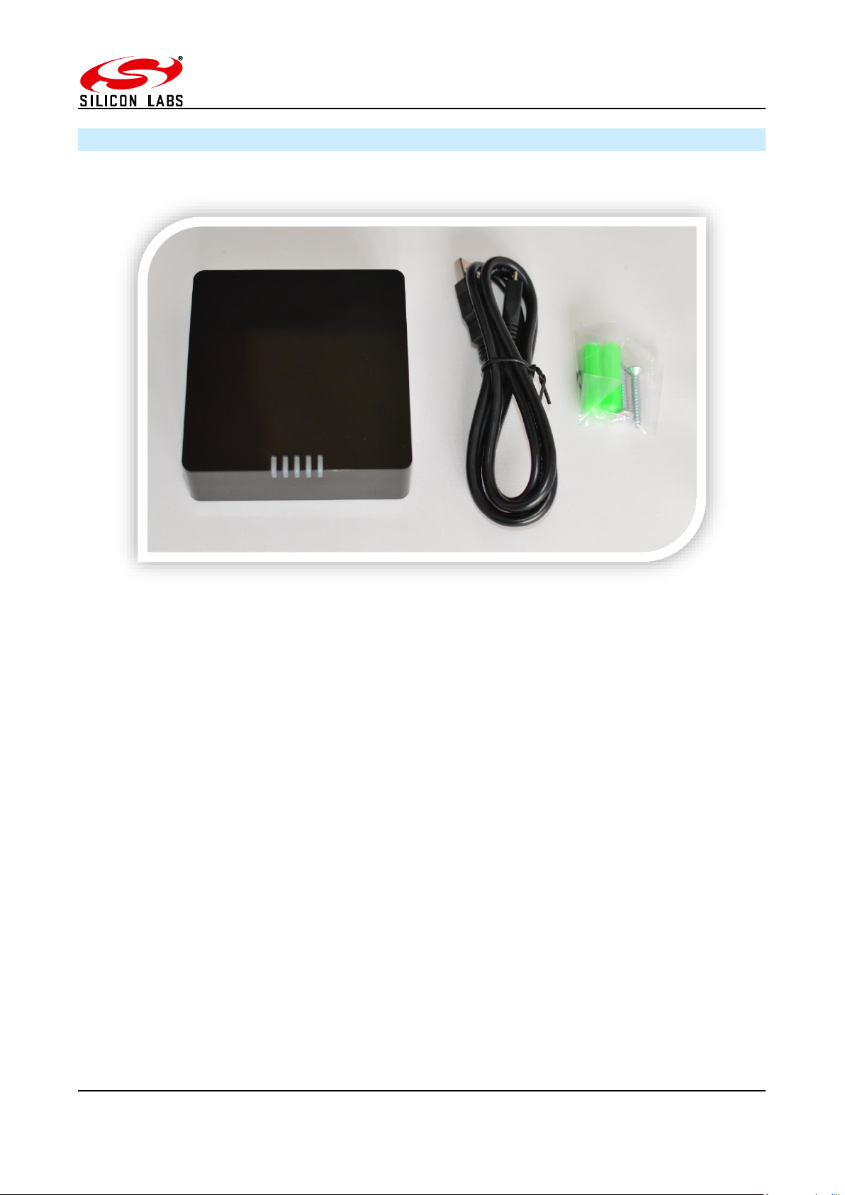
3 Package Contents
The package contains the following items,
a. ZigBee Communications Gateway
b. Micro USB power cable
c. Mounting screws
Figure 1: Package contents
©2016 Silicon Labs -5- ZigBee Communications Gateway
Page 6
ZigBee Communications Gateway
Model Number
GW357
RF Interface
ZigBee Pro
RF Output Power
+8dBm
Antenna
Half-wave Dipole Antenna 2dBi Gain or Integrated Antenna
Clock Battery
1x 3V 220mAh Sony CR2032 Battery
Power Source
5Volts @ 500mA via USB Micro Connector
Charging source should be current limited
Ethernet
RJ45 10/100Mbps
Power Over Ethernet
(optional)
802.3af Compliant Class 1 Device
Operating Temperature
-20 to 70C
Humidity
95% TH Non-condensing
IP Rating
IP20 (subject to testing)
Net Weight
110g
RS485/RS232
Baud rate: 2400, 4800, 9600, 19200, 38400, 57600, 115200
Parity: none, odd, even
Stop bits: 1 or 2
RS485 120Ω termination resistor built in
GW
Gateway
GW357
Core Silabs IC
GW357-X
1st module
1 = ETRX357
2 = ETRX357HR
3 = ETRX357-LRS
4 = ETRX357-HR-LRS
GW357-0X
2nd module
GW357-00-X
Power of Ethernet (P)
GW357-00-0-X
WiFi or GSM (W or G)
GW357-00-0-0-X
RS232/RS485 (1=yes 0=No)
GW357-00-0-0-0-X
SD Memory Card size i.e. 4, 8 etc.
4 Specifications
4.1 Order Codes
4.2 Examples
GW357-11-P-W-1-8 Gateway with 2xETRX357 module, Power-over-Ethernet, WiFi,
RS232/RS485 and an 8MB SD Memory Card
GW357-1 Basic Gateway with 1xETRX357 module
GW357-30-0-0-1 Gateway with 1xETRX357-LRS and RS232/RS485
©2016 Silicon Labs -6- ZigBee Communications Gateway
Page 7
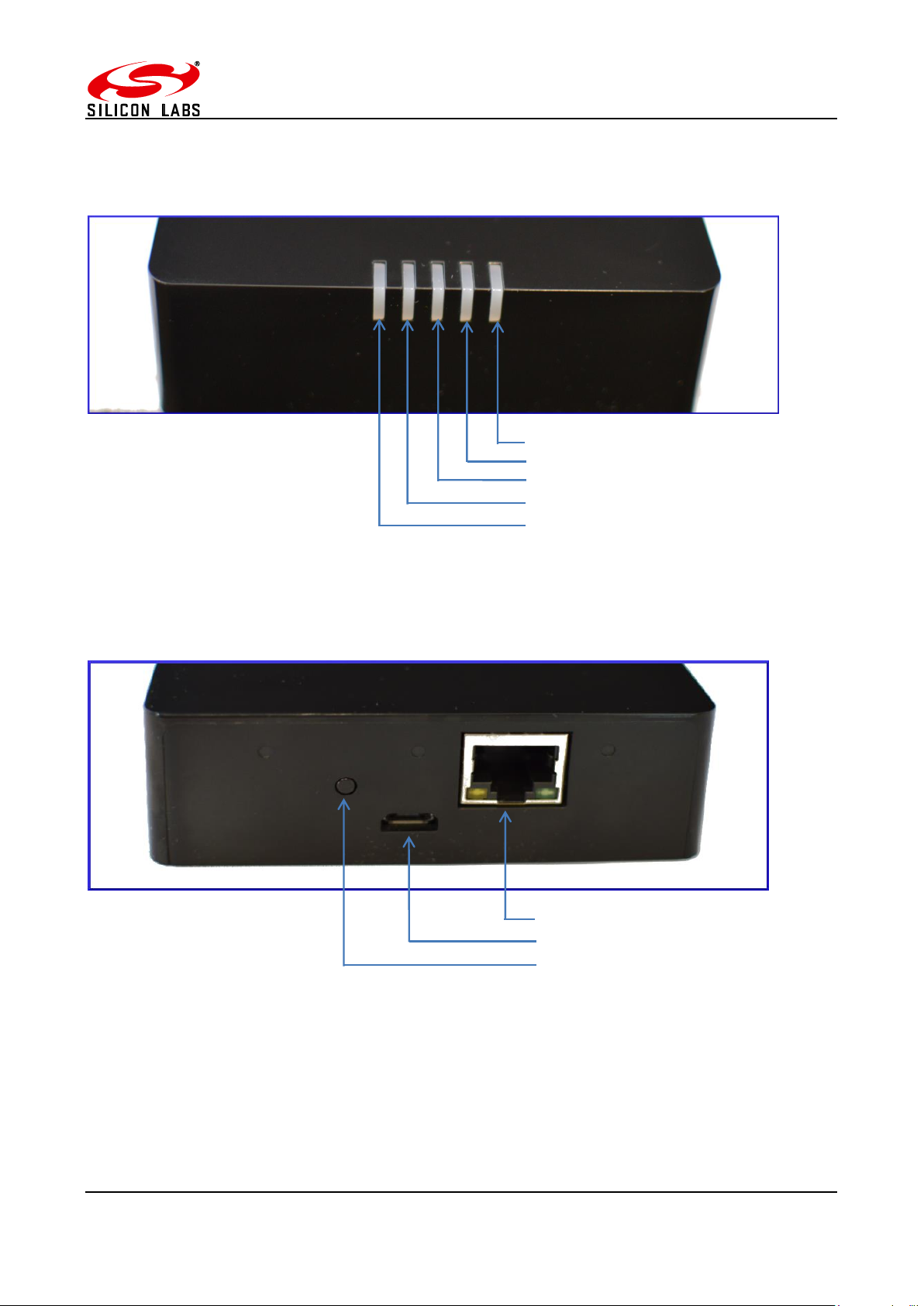
Ethernet connector RJ45
Micro USB power socket
Button-2 (B2)
nd
Interface Activity LED
Gateway Activity LED
Link Status LED
1st ETRX3 Status LED
Layout
ZigBee Communications Gateway
Figure 2: Gateway front view
Figure 3: Gateway without RS232/RS485 back view
©2016 Silicon Labs -7- ZigBee Communications Gateway
Page 8
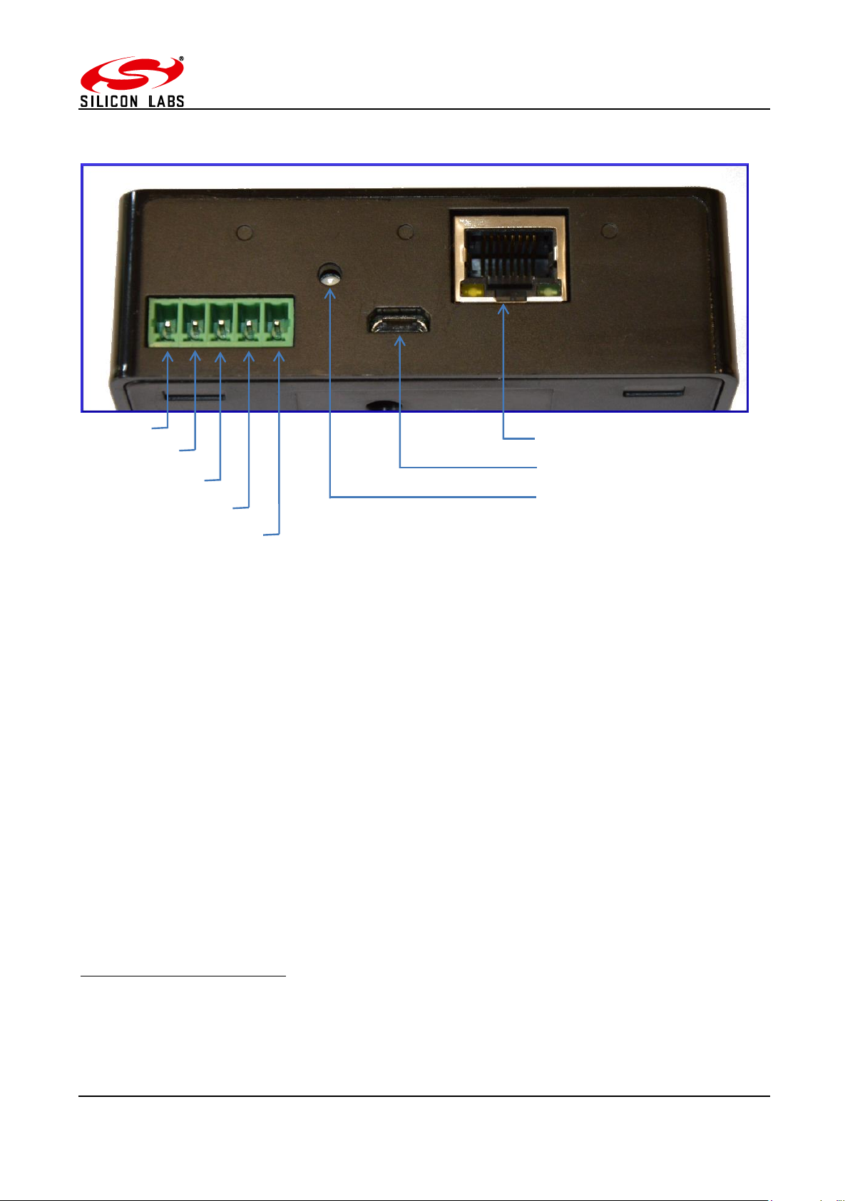
ZigBee Communications Gateway
1
RS485 D-
RS485 D+
RS232 RX
GND
RS232 TX
Ethernet connector RJ45
Micro USB power socket
Button-2 (B2)
Figure 4: Gateway with RS232/RS485 back view1
Compatible connectors for RS232/RS485 port
MULTICOMP - MC000099
MULTICOMP - MC000107
MULTICOMP - MC000115
©2016 Silicon Labs -8- ZigBee Communications Gateway
Page 9
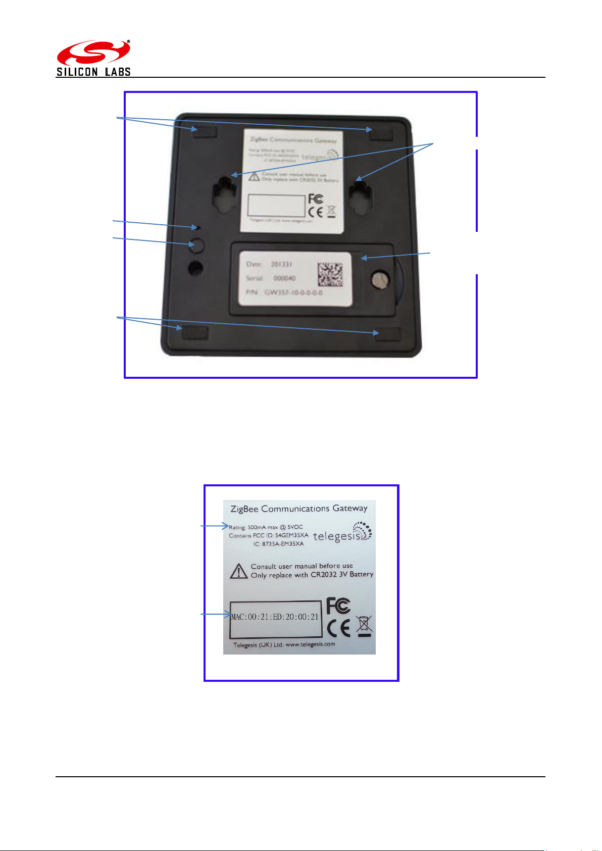
ZigBee Communications Gateway
Mounting holes
Opening for
card holder
Button-1 (B1)
Button-3 (B3)
Anti-slip pads
Anti-slip pads
Power supply
ratings
Gateway MAC
address
battery and SD
Figure 5: Gateway bottom view
©2016 Silicon Labs -9- ZigBee Communications Gateway
Figure 6: Top label
Page 10
ZigBee Communications Gateway
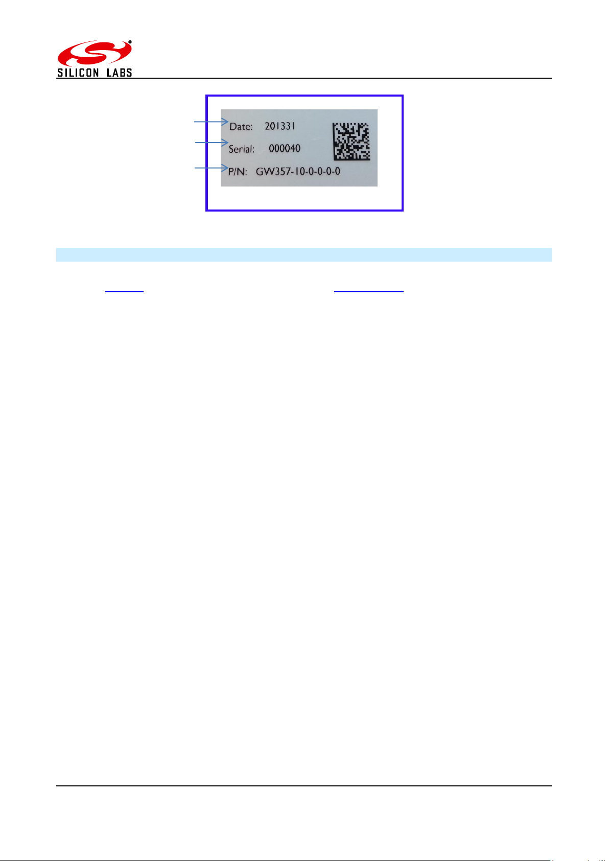
Manufacture date
Gateway serial number
Gateway model number
Figure 7: Bottom label
4.3 Power
The Gateway can be powered ON by plugging in the micro USB cable in the socket provided as
shown in figure-3 with power source as specified in the Specifications. Selected models of gateway
incorporating Power over Ethernet (PoE) can be powered on using the PoE injector through RJ45
cable.
©2016 Silicon Labs -10- ZigBee Communications Gateway
Page 11

ZigBee Communications Gateway
Sequence
Number
Gateway State
1st
ETRX3
Status
LED
Link
Status
LED
Gateway
Activity LED
Interface
Active
LED
2nd
ETRX3
Status
LED
1
Power UP Sequence
ON
Red +
Green
Blinking
Amber for
5 sec
OFF
ON
All LEDs will turn ON and then following blink one after
the other twice except for the ETRX3 Status LEDs
which are controlled by ETRX3 ZigBee modules
2
Ethernet link inactive
-
Red
Blinking
Amber
-
3
Ethernet link active
-
Green
OFF
-
-
4
Any socket connected to
either ZigBee module
OR
Web Terminal connected
- - -
Green
-
5
Any communication with
ZigBee modules
OR
Any communications on
Ethernet lines
- - Blinking
Amber
-
-
2nd ETRX3 Status LED
Interface Active LED
Gateway Activity LED
Link Status LED
1st ETRX3 Status LED
4.4 LED Indicators
Table 2: LED Sequence table
©2016 Silicon Labs -11- ZigBee Communications Gateway
Page 12

ZigBee Communications Gateway
2
4.5 Buttons Actions
The Gateway has three hardware buttons as shown in the Layout which can perform multiple
functions as described in this section.
1. Button 1 (B1)
2. Button 2 (B2)
3. Button 3 (B3)
Restore factory defaults
Follow the following procedure with buttons in order to restore the factory default configuration
settings on the Gateway using B3 and B1.
1. Press and hold B3
2. Then with B3 pressed, press and hold B1 for approximately 3 seconds after which the
Gateway reboots and LED power up sequence is seen.
Gateway reboot
Press B3 and hold for 5 seconds to reboot the Gateway.
Gateway recovery mode
Perform following procedure to put the Gateway in recovery mode2.
1. Press and hold B3 until gateway reboots.
2. At power up hold B2 and wait for 3 seconds.
3. The Gateway will be in recovery mode now.
Issue ZigBee command
Button B2 is used to issue custom ZigBee command to the 1st ETRX3 ZigBee module which can be
configured in Button Command section of the Gateway Configurations as shown below.
So whenever the B2 is pressed the command (“AT+BCAST:00,hello” by default) is issued to the 1st
ETRX3 ZigBee module.
Recovery mode not implemented in initial release but will be added in subsequent release soon.
©2016 Silicon Labs -12- ZigBee Communications Gateway
Page 13

ZigBee Communications Gateway
5 Functionality
5.1 Start-up
Turn ON the ZigBee Communications Gateway by inserting the micro USB power cable into the
socket shown in figure 3. The LEDs on the front panel will light up as described in the LED’s
Sequence table. Once the Start-up LED sequence is complete the gateway will continuously look for
an Ethernet link which is indicated by LED sequence-3. Insert the Ethernet cable in the RJ45 socket
shown in figure 3. The gateway will try to obtain an IP address by using DCHP (by default DHCP is
enabled but the user can also set static IP address for the Gateway). Once an IP address is allocated
successfully the LED sequence-4 is displayed on the LED panel.
5.2 Gateway Discovery
Discovery on a windows-7 PC
Gateway implements UPnP discovery service so the user can directly go to “Network settings” and
look for devices under “Network Infrastructure” category. The Gateway will show up as ZigBee
Communications Gateway as shown below. Navigate to properties by right clicking on the device to
view the device properties. Browse to the IP address shown in the device properties or alternatively
double click on the device to navigate to the webpage hosted by Gateway.
Figure 8: Device Discovery
©2016 Silicon Labs -13- ZigBee Communications Gateway
Page 14

ZigBee Communications Gateway
import socket, traceback, commands
host = '' # Bind to all interfaces
port = 14099
#start a udp socket server to listen on port 14099
s = socket.socket(socket.AF_INET, socket.SOCK_DGRAM)
s.setsockopt(socket.SOL_SOCKET, socket.SO_REUSEADDR, 1)
s.setsockopt(socket.SOL_SOCKET, socket.SO_BROADCAST, 1)
s.bind((host, port))
print "Waiting for Telegesis Gateway:"
while 1:
try:
message, address = s.recvfrom(8192)
print "Telegesis Gateway Found on IP Address:
%r"%(address[0])
except (KeyboardInterrupt, SystemExit):
raise
Figure 6: Discovery Script Figure 9: Discovery Python Script
Discovery on other platforms:
On other platforms where UPnP services are not available, the device can be discovered using the
following python script which basically listens to the UDP broadcast on port 14099 by the gateway
once every minute.
Run the above script from command line and the output window would show the IP addresses of
the ZigBee Communications Gateways in the network as shown below
Figure 10: Discovery Output
©2016 Silicon Labs -14- ZigBee Communications Gateway
Page 15

ZigBee Communications Gateway
5.3 Gateway Webserver
ZigBee Communication Gateway hosts a http webserver to serve webpages which help the user to
configure the Gateway and communicate with the ZigBee device via a simple web interface.
Authentication
The http webserver is protected by basic authentication hence a valid username “admin” and
password “password” must be provided when prompted to access the webpages. The password
can be changed through the GW357 Configuration webpage as explained in the later section.
Figure 11: HTTP server authentication
©2016 Silicon Labs -15- ZigBee Communications Gateway
Page 16

ZigBee Communications Gateway
Web Pages
Following web pages are served by the http web server on the ZigBee Communications Gateway
5.3.2.1 GW357 Configuration
The Gateway configuration page is the main page of the http webserver. This page provides access
to the configuration parameters of the Gateway.
Figure 12: Configurations Page
©2016 Silicon Labs -16- ZigBee Communications Gateway
Page 17

ZigBee Communications Gateway
3
5.3.2.1.1 Gateway Configuration
a. Current Firmware Info
This field gives information about the current firmware running on the gateway.
b. Web Terminal
This option enables or disables the access to ZigBee module via the web terminal. The
Gateway provides an access to the ZigBee module via Web Terminal page which can be
used to issue commands to the ZigBee module and monitor the response of the module. The
Web Terminal only supports communication in ASCII.
Default value is enabled.
c. Dialout TCP Sockets
Enable
The Gateway can establish an outgoing TCP socket connections to a specified dialout
addresses and port numbers. This option can enable or disable the outgoing socket
connections for both the ZigBee modules.
Default value is disabled.
Out 1 Address
The address specified in this option is used by the gateway to establish the outgoing socket
connection for the 1st ETRX3 ZigBee module. The dialout address can either be an IP
address or a host name.
Out 1 port
This item specifies the port number for the dialout connection from 1st ETRX3 ZigBee module.
Out 2 Address3
The address specified in this option is used by the gateway to establish the outgoing socket
connection from the 2nd ETRX3 ZigBee module. The dialout address can either be an IP
address or a host name.
This option only available in Gateway models with two ZigBee modules on-board. Please refer order codes
©2016 Silicon Labs -17- ZigBee Communications Gateway
Page 18

ZigBee Communications Gateway
4
5
Out 2 port3
This item specifies the port number for the dialout connection from 2nd ETRX3 ZigBee
module.
Secure Connection
This option enables the SSL on the outgoing socket connection4.
d. Dialin TCP Sockets
Module 1 Enable
The Gateway also allows an incoming TCP socket connection on a specified port which
enables access to the 1st ETRX3 ZigBee module.
Module 1 Port
The IP port number to access the 1st ETRX3 ZigBee module via incoming TCP socket.
Module 1 IP Range MIN
The lowest IP address that can make a dial in socket connection to module 1 on gateway.
Module 1 IP Range MAX
The highest IP address that can make a dial in socket connection to module 1 on gateway.
Module 2 Enable5
The Gateway also allows an incoming TCP socket connection on a specified port which
enables access to the 2nd ETRX3 ZigBee module.
Module 2 Port5
The IP port number to access the 2nd ETRX3 ZigBee module via incoming TCP socket.
Module 2 IP Range MIN
The lowest IP address that can make a dial in socket connection to module 2 on gateway.
Module 2 IP Range MAX
The highest IP address that can make a dial in socket connection to module 2 on gateway.
5
5
The SSL is not implemented in current release.
This option only available in Gateway models with two ZigBee modules on-board. Please refer order codes
©2016 Silicon Labs -18- ZigBee Communications Gateway
Page 19

ZigBee Communications Gateway
e. RS232/RS485 Tunnelling
This is only available on GW357 gateway models which have the RS232\RS485 option (see
the order codes table.) A “Module 2” check box will also be present if your GW357 has a
second ETRX3 ZigBee module fitted.
This option creates a direct connection between the RS232 or RS485 port on the gateway
and the ETRX3 ZigBee module.
The GW357 doesn’t support addressing in multidrop networks. Any data received on the
RS485 port will be automatically forwarded to the ETRX3 ZigBee module.
f. RS232/RS485 Port Configuration
This option is only available on GW357 gateway models which have the RS232\RS485 option
(see the order codes table.)
Here the user can select the RS232 and RS485 port settings. Note: it is recommended
(although not a requirement) that the RS232/RS485 port on the gateway and the ETRX3
ZigBee module have the same baud rate. The gateway has a limited capacity to buffer
messages; ensuring the baud rates are the same removes the potential for a buffer overflow
in the RX or TX paths.
g. Discovery
This option is enables the Gateway to send discovery broadcasts by UDP on port 14099
once every minute. This option is enabled by default.
h. Button Command
This is a command string that will be sent to the 1st ETRX3 ZigBee module each time the
Button-2 (B2) is pressed.
©2016 Silicon Labs -19- ZigBee Communications Gateway
Page 20

i. Gateway Time
Time Server
The Gateway implements SNTP client which can update Gateway time from a valid time
server specified in time server field.
Current Time
The current time of the gateway is displayed in this field when the page is loaded or
is clicked.
After changing any settings on the webpage must be clicked in order to apply the
changes to Gateway configuration. Following message will be displayed to confirm the
change.
ZigBee Communications Gateway
j. Disable Web Server
The HTTP webserver running on the gateway can be disabled using this option on the
configurations page.
Once it is disabled only following page will be accessible to user. This feature is added to
avoid any unauthorized or unintended changes in the gateway configuration. A CGI-script
can be run on the gateway to re-enable the webserver. The CGI script to re-enable the
webserver is “en-wp.cgi”
©2016 Silicon Labs -20- ZigBee Communications Gateway
Page 21

ZigBee Communications Gateway
5.3.2.1.2 IP Configuration
a. Current IP Configurations
IP address
The current IP address of the Gateway is displayed in this field.
MAC address
The MAC address of the Gateway is displayed in this field.
b. DHCP Configuration
DHCP Enable
If this option is enabled the Gateway can acquire IP configurations like IP address, subnet
mask, default gateway and the DNS server dynamically by using DHCP protocol. If the DHCP
option is not selected then stored Static IP configuration is used to setup the network
interface.
c. Static IP Configurations
IP Address
The gateway uses the IP address specified in this field as static IP when DHCP option is not
selected.
Subnet Mask
The gateway uses the subnet mask specified in this field as subnet mask when DHCP option
is not selected.
Default Gateway
The gateway uses the default gateway specified in this field as default gateway when DHCP
option is not selected.
DNS Server
The gateway uses the DNS server specified in this field as DNS server when DHCP option
is not selected.
©2016 Silicon Labs -21- ZigBee Communications Gateway
Page 22

ZigBee Communications Gateway
6
After changing any settings in the IP configuration must be clicked in order to apply the
changes in Gateway. Following message will be displayed to confirm the change.
Click refresh to verify if the settings are changed successfully.
5.3.2.1.3 Restoring Factory Defaults
The factory settings can be restored by clicking . The factory defaults can also
be restored by combination of hardware button presses as described in Buttons Actions
section. Following are the factory defaults:
Default Gateway Configurations
1. Web Terminal : Enabled
2. Dialout : Disabled
3. Out 1 Address : 192.168.204.107
4. Out 1 Port : 4094
5. Out 1 Address : 192.168.204.107
6. Out 1 Port : 4095
7. Secure Connection6 : Disabled
8. Module 1 Enable : Enabled
9. Module 1 Port : 4096
10. Module 2 Enable : Enabled
11. Module 2 Port : 4097
12. Time Server : 0.uk.pool.ntp.org\0
13. Username : admin
14. Password : password
Default IP Configurations
1. DHCP Enable : Enabled
2. Static IP Address : 192.168.204.121
3. Subnet Mask : 255.255.255.0
4. Default Gateway : 192.168.204.10
The SSL is not implemented in current release.
©2016 Silicon Labs -22- ZigBee Communications Gateway
Page 23

ZigBee Communications Gateway
5.3.2.1.4 Changing the Admin Password
User can change the Gateway’s default password by clicking which will display
following fields on the configurations page. Fill in all the fields and hit change to apply new
password.
Once the password is changed successfully the following message will be displayed.
Password can also be reset to factory default by restoring factory default configurations
mentioned in Buttons Actions.
©2016 Silicon Labs -23- ZigBee Communications Gateway
Page 24

ZigBee Communications Gateway
7
8
5.3.2.2 ZigBee Interface Configurations
Figure 13: ZigBee Interface Configurations page
The Gateway comes with Telegesis ZigBee AT-commands7 Firmware programmed onto the
assembled ETRX3 ZigBee module. This firmware communicates at baud rate settings of 192008N1. The ZigBee Interface Configurations page is useful to change8 the serial settings of the gateway
serial ports connected to the ETRX3 ZigBee modules. This page also provides the options to reset
the selected ETRX3 ZigBee module and to start the bootloader.
a. Select Module
This field selects the ETRX3 ZigBee module to apply the settings to (there can be two module
as per the model number of gateway).
b. Module Control
Reset Module
Click for gateway reset the selected ETRX3 module.
Start Bootloader
Click to start the bootloader on selected ZigBee module. The standard ATCommand firmware has serial Bootloader which can be used to upgrade the ZigBee firmware
in the selected module. Process of upgrading ETRX3 ZigBee firmware in standard Gateway
is described in the Appendix A. The bootloader is initiated by holding down the PA5 pin of
the EM35x and then issuing a hardware reset to the module
c. Serial Settings
Select the serial settings for the selected module and click to apply the settings
Please refer AT-commands documentation at Telegesis document centre
The Serial Port settings only apply to the Gateway. For correct operation, the Serial Port settings of the
ETRX3 module must be changed to match the new Gateway setting before changing the Gateway parameters
©2016 Silicon Labs -24- ZigBee Communications Gateway
Page 25

ZigBee Communications Gateway
9
10
Terminal Status
ZigBee output
Gateway Time
ZigBee input
5.3.2.3 Web-Terminal
`
Figure 14: Web Terminal page
The Web Terminal is a simple web interface to communicate with the 1st ETRX3 ZigBee module on
the Gateway. User can issue AT-Commands9 to the module in ZigBee input command box, click
and monitor the response in the ZigBee output window.
The Terminal status shows the current status of the web terminal and the Gateway time is also
displayed in the top right of the ZigBee output window,
Terminal Disabled Status:
If the Web Terminal option is disabled in the Configurations page Terminal status as shown above
will be displayed. No commands can be issued to the ZigBee module via Web Terminal if this status
is been displayed.
Terminal Enabled Status:
When the Web Terminal connects successfully to the ZigBee module above status will be displayed.
The Gateway time will also start updating once every second. Now, the user may enter an AT-
Command in ZigBee input box and click issue the command10 to the ZigBee module and
expect the response in approximately one sec.
©2016 Silicon Labs -25- ZigBee Communications Gateway
Please refer AT-commands documentation at Telegesis document centre
Note: Pressing Enter Key on Keyboard will NOT send the command but will refresh the page.
Page 26

ZigBee Communications Gateway
5.3.2.4 Firmware Upgrade
The Gateway firmware can be updated over Ethernet. To perform Gateway firmware upgrade,
navigate to “http://<gateway_ip_address>/bootload.html” page which looks like below.
Figure 15: Firmware Upgrade page
Stored Image Info
This section gives the information of the Gateway firmware image stored in the Gateway.
Image Header
Each image stored in the Gateway has an Image Header for identifying the type of image. This field
displays the image header of selected Image type.
Firmware Version
This field displays the firmware version of image stored.
Image Size
This field displays the size of stored image in bytes.
©2016 Silicon Labs -26- ZigBee Communications Gateway
Page 27

ZigBee Communications Gateway
11
Upload Images
Select Upload Image Type:
Select the type of image to be uploaded to the Gateway. Currently Gateway supports three types of
images
a. Gateway Image
This is the gateway upgrade image which will replace the current Gateway firmware when
gateway is rebooted with Update Gateway flag enabled.
b. Bootloader Image
This is the recovery bootloader11 upgrade image which will replace the current secondary
bootloader when gateway is rebooted with Update Bootloader flag is enabled.
c. Configuration Settings Image
All the configurations settings mentioned in Configurations page can be updated by this
image type. The settings will get applied after the gateway is rebooted. No flag is necessary
to be enabled for the configuration settings to be update.
Image Upload Process
Click which opens a dialogue box to navigate to the image, navigate to appropriate file
and click open.
Now click a pop-up box will open to confirm correct file is uploaded. Click OK to
proceed. Gateway activity LED will be blinking while the file is being transferred. If the image is
uploaded and stored successfully in Gateway “FW image sent successfully” message is displayed
in a new tab in the browser.
Recovery bootloader mechanism is not implemented in the initial release but will be implemented in
subsequent release soon.
©2016 Silicon Labs -27- ZigBee Communications Gateway
Page 28

ZigBee Communications Gateway
Update Flags and Reboot
Update Gateway
If this flag is enabled upon reboot the gateway will validate the Gateway Image stored by image
upload process mentioned above and updates the gateway firmware if a valid image is present.
Update Bootloader
If this flag is enabled upon reboot the gateway will validate the Bootloader Image stored by the image
upload process mentioned above and updates the recovery bootloader firmware if a valid image is
present.
Wait for Serial Commands
The Gateway can accept some serial commands at start-up (available only on models with RS232RS485 port present). If this flag is enabled the gateway will wait for 5 sec to accept any serial
commands on the RS232 lines and then jump to the main gateway application.
Enable the appropriate flags and click buttons to upgrade the gateway with
stored image.
Upgrading may take few minutes, be patient and do not interrupt the upgrade process until power
up sequence is indicated on the LED panel. The upgrade process will be indicated by blinking of
gateway activity LED.
©2016 Silicon Labs -28- ZigBee Communications Gateway
Page 29

ZigBee Communications Gateway
5.3.2.5 Support
Support link will redirect to telegesis Support page on the internet http://www.telegesis.com/support/
5.3.2.6 Logout
Logout will end current session and “Logged out successfully” message will be displayed and the
user will need to authenticate with username and password at the next login.
Figure 16: Logout page
©2016 Silicon Labs -29- ZigBee Communications Gateway
Page 30

ZigBee Communications Gateway
6 Appendix A
6.1 Bootloading ETRX3 ZigBee module
The procedure to upgrade firmware on ETRX3 module over a TCP socket is as described below.
1. For this example assume the firmware of 1st ETRX3 ZigBee module is to be updated remotely
over a TCP socket.
2. Make sure dialin socket is enabled for the 1st ETRX3 ZigBee module as shown below
3. Connect to the Gateway’s dialin socket for the 1st ETRX3 ZigBee module using Telegesis
terminal (Version 4 or higher) as shown below.
Figure 17: Dialin socket connection
©2016 Silicon Labs -30- ZigBee Communications Gateway
Page 31

ZigBee Communications Gateway
4. The LED sequence 4 should be indicated by LED panel.
5. Navigate to ZigBee Interface Configuration and Select Module 1 as shown below.
6. Click to start the bootloader on selected ZigBee module.
7. Change the baudrate to 115200 and click .
8. On Telegesis terminal hit Enter key to see following prompt
Figure 18: ETRX3 Bootload prompt
©2016 Silicon Labs -31- ZigBee Communications Gateway
Page 32

ZigBee Communications Gateway
9. Press “1” to see character ‘C’ displayed periodically as shown which indicates the ZigBee
module is ready to receive upgrade image file via XMODEM
Figure 19: Ready to receive upgrade image file via XMODEM
10. Go to Tools->Transfer File (XMODEM) and send the appropriate upgrade image file.
11. Once successful change the baudrate of module according to upgraded firmware and the
ZigBee module will communicate according to the new firmware. For Telegesis R3xx
firmware the default baud rate is 19200-8N1
6.2 Cleaning
Dust or wipe only with damp cloth; do not allow moisture to penetrate the enclosure. Do not use
aggressive cleaning agents
©2016 Silicon Labs -32- ZigBee Communications Gateway
Page 33

Smart.
Connected.
Energy-Friendly
Products
www.silabs.com/products
Disclaimer
Silicon Laboratories intends to provide customers with the latest, accurate, and in-depth documentation of all peripherals and modules available for system and software implementers using
or intending to use the Silicon Laboratories products. Characterization data, available modules and peripherals, memory sizes and memory addresses refer to each specific device, and
"Typical" parameters provided can and do vary in different applications. Application examples described herein are for illustrative purposes only. Silicon Laboratories reserves the right to
make changes without further notice and limitation to product information, specifications, and descriptions herein, and does not give warranties as to the accuracy or completeness of the
included information. Silicon Laboratories shall have no liability for the consequences of use of the information supplied herein. This document does not imply or express copyright licenses
granted hereunder to design or fabricate any integrated circuits. The products are not designed or authorized to be used within any Life Support System without the specific written consent
of Silicon Laboratories. A "Life Support System" is any product or system intended to support or sustain life and/or health, which, if it fails, can be reasonably expected to result in significant
personal injury or death. Silicon Laboratories products are not designed or authorized for military applications. Silicon Laboratories products shall under no circumstances be used in
weapons of mass destruction including (but not limited to) nuclear, biological or chemical weapons, or missiles capable of delivering such weapons.
Trademark Information
Silicon Laboratories Inc.® , Silicon Laboratories®, Silicon Labs®, SiLabs® and the Silicon Labs logo®, Bluegiga®, Bluegiga Logo®, Clockbuilder®, CMEMS®, DSPLL®, EFM®, EFM32®,
EFR, Ember®, Energy Micro, Energy Micro logo and combinations thereof, "the world’s most energy friendly microcontrollers", Ember®, EZLink®, EZRadio®, EZRadioPRO®, Gecko®,
ISOmodem®, Precision32®, ProSLIC®, Simplicity Studio®, SiPHY®, Telegesis, the Telegesis Logo®, USBXpress® and others are trademarks or registered trademarks of Silicon Laboratories Inc. ARM, CORTEX, Cortex-M3 and THUMB are trademarks or registered trademarks of ARM Holdings. Keil is a registered trademark of ARM Limited. All other products or brand
names mentioned herein are trademarks of their respective holders.
Silicon Laboratories Inc.
400 West Cesar Chavez
Austin, TX 78701
USA
Quality
www.silabs.com/quality
Support and Community
community.silabs.com
http://www.silabs.com
 Loading...