

Page 1

AN1292: Si5332-AM SmartClock™ Fault
Detection and Monitoring
What is the Si5332-AM family and why use it in automotive applications?
Automotive electronics
of quartz crystals and quartz crystal oscillators to provide timing references for all the
required system clocks. One of the largest drawbacks to this approach is that quartzbased components have the highest FIT rates of any electronic systems component,
which greatly affects system reliability. As designs continue to adopt processors with
greater functionality with higher speed SerDes, Ethernet connectivity, and PCI-Express
data buses, the need for more reference clocks arises, with both single-ended and differential formats, and lower RMS phase jitter.
The Si5332-AM family of clock generators is designed to overcome the challenges associated with increasingly complex clock tree design in automotive electronics. These
devices are capable of supporting up to 12 unique frequency outputs, all of which can
be individually programmed to its own electrical format (i.e., LVCMOS, LVDS, HCSL,
etc.). By consolidating the functionality of many pieces of quartz-based components into a silicon-based clock generator, system designers can eliminate many points of failure and greatly improve overall system reliability.
In addition to component count reduction and reliability improvements, clock generators
offer numerous additional benefits that are not available from quartz-based timing components. The Si5332-AM clock generators provide in-system programming capability,
spread spectrum modulation, output enable control, and frequency selection capabilities. To help system designers meet system level safety goals, the Si5332-AM devices
also come equipped with SmartClock features that include redundant reference inputs,
health monitoring, fault detection, communication with an external safety manager, primary/back-up reference source switching, and AlwaysON outputs. This application
note provides an overview of the SmartClock features and outlines system level examples on how to implement them.
system designs have traditionally depended on multiple pieces
KEY POINTS
• SmartClock features
• System implementation examples
silabs.com | Building a more connected world. Rev. 0.1
Page 2

AN1292: Si5332-AM SmartClock™ Fault Detection and Monitoring
Focus of this Application Note: Si5332-AM SmartClock Features
1. Focus of this Application Note: Si5332-AM SmartClock Features
This application note will specifically focus on the integrated clock fault detection features of the Si5332- AM Clock Generator family.
For more details on the many other features and benefits of the Si5332-AM device family and other automotive timing products, please
browse the link below.
https://www.silabs.com/timing/automotive-timing-solutions
The Si5332-AM programmable clock generators can be easily customized to individual design clock tree requirements by creating a
configuration file using the ClockBuilder Pro Software Utility. Users can enable the Si5332-AMs SmartClock features during configuration file development. ClockBuilder Pro can be downloaded for free:
https://www.silabs.com/products/development-tools/software/clockbuilder-pro-software
silabs.com | Building a more connected world. Rev. 0.1 | 2
Page 3

AN1292: Si5332-AM SmartClock™ Fault Detection and Monitoring
SmartClock Health Monitoring and Fault Detection Features within Si5332-AM
2. SmartClock Health Monitoring and Fault Detection Features within Si5332-AM
Shown below is a generic block diagram of the Si5332-AM clock generator family of devices. The three devices in this family are as
follows:
• Si5332-AM1: 2 input (xtal + 1 CLKIN), 6 output
• Si5332-AM2: 3 input (xtal + 2 CLKIN), 8 output
• Si5332-AM3: 3 input (xtal + 2 CLKIN), 12 output
LDO
OSC
Low
CLKIN_2
Jitter
PLL
CLKIN_3
LOS
FOOF
CLKIN_SEL0
CLKIN_SEL1
GPIs
2.1 Fault Monitor Block Overview
The Si5332-AM
ment in ClockBuilder Pro. System designers can choose to enable SmartClock features using some of the Universal GPIO pins, as
highlighted within the red box in Figure 2.1 Si5332-AM Block Diagram on page 3. When enabling these features, SIlicon Labs recommends the use of a crystal reference source, as well as a backup input clock reference source. The Si5332-AM2 (8-output) and Si5332AM3 (12-output) include a third reference input.
The Fault Monitor continuously monitors the status of the input clock reference to the PLL. If a fault condition is detected, a signal is
provided to an external system safety manager or MCU, which can then direct the Si5332-AM to switch the reference source from the
primary to the backup input source. The Fault Monitor block provides 4 signals, 2 input and 2 output, as follows:
• LOS (Loss of Signal) output: This output asserts when the frequency of the selected input clock falls below a set threshold. This
frequency threshold is set by our CBPro configuration software based on input clock frequency.
• FOOF (Fast Out of Frequency) output: This output asserts when the difference between the PLL input reference frequency and PLL
feedback frequency falls outside of a set band. FOOF assertion is an indication the PLL has either fallen out of lock or other PLL
fault condition has occurred and the PLL may either be unlocked or otherwise not operational. The band limits are automatically set
by CBPro.
• CLKIN_SEL[1:0]: Two logic inputs used to select one of 4 possible input clock sources for PLL reference.
includes a bank of Universal GPIO pins that can be assigned to numerous functions during configuration file develop-
Fault
Monitor
Status /
Control
Figure 2.1. Si5332-AM Block Diagram
Synth
Multi
Synth
÷ INT
÷ INT
÷ INT
÷ INT
÷ INT
÷ INT
÷ INT
6/8/12
Output
Clock
s
Multi
2.2 External Action Required on Either LOS or FOOF Assertion
The LOS and FOOF signal outputs indicate that a fault condition has occurred. No action is automatically taken by the Si5332-AM as a
result of these fault indications. An external device, such as an MCU or other system safety manager, must monitor LOS and FOOF
outputs from the Si5332-AM,and can make a system level decision on potential courses of action for maintaining acceptable levels of
system safety. The external device can then provide instructions back to the Si5332-AM to migrate from the faulted input reference to
the backup input reference, or take action at the system level based on the severity of the detected fault.
silabs.com | Building a more connected world. Rev. 0.1 | 3
Page 4

AN1292: Si5332-AM SmartClock™ Fault Detection and Monitoring
SmartClock Health Monitoring and Fault Detection Features within Si5332-AM
2.3 CLKIN_SEL[1:0] Input Clock Selects: Input Clock Selection and Validation
CLKIN_SEL1 CLKIN_SEL0 Clock Selected Note
0 0 Input disabled To test input clock fault condition.
0 1 Crystal Oscillator
1 0 Clock 2 Input
1 1 Clock 3 Input Only on -AM2 and -AM3 devices.
The CLKIN_SEL[1:0] inputs can be used to select which input clock source is to be used by the on-chip PLL for its clock reference.
With this input selection capability an external device, such as an MCU, can be used to intelligently select an alternate (redundant) input
clock reference
can attempt to recover from this fault condition by selecting an alternate clock source.
In addition, when running system power-up or other diagnostics, the MCU software can test the functionality of LOS and FOOF by selecting the Input Disabled setting and then confirming assertion of LOS and FOOF as a result. Similarly, the MCU software can also
confirm proper operation of any alternate clock input sources by selecting the alternate source(s) and confirming LOS and FOOF are
not asserted.
as part of a fault recovery plan. For example, if assertion of the LOS signal is detected by an MCU, the MCU software
silabs.com | Building a more connected world. Rev. 0.1 | 4
Page 5

AN1292: Si5332-AM SmartClock™ Fault Detection and Monitoring
System Implementation Examples Of Using Si5332-AM SmartClock Features
3. System Implementation Examples Of Using Si5332-AM SmartClock Features
Several different use-case examples are presented below, complete with system level block diagrams showing how the Si5332-AM device can be implemented with the SmartClock features enabled. When coupled with an external MCU or system safety manager, the
device provides the highest degrees of health monitoring, fault detection, and redundancy. These configurations highlight the flexibility
in tailoring a solution to meet different levels of clocking fault detection and redundancy.
Devices noted in the block diagram that are highlighted in dark orange are the external devices and signals that support the various
fault detection and control scenarios. For each configuration scenario, an associated example software flowchart of operations is provided. These flowcharts are meant to show how the input reference health monitoring and fault detection/recovery plan can be implemented.
silabs.com | Building a more connected world. Rev. 0.1 | 5
Page 6

Power-up
Diagnostics
pass
Ensure input mux
set to Xtal input
Wait for Device
Active
LOS &
FOOF
inactive
?
Normal
Operation
Y
N
Handle clock
failure.
LOS or FOOF
assertion during
Normal Operation
System Implementation Examples Of Using Si5332-AM SmartClock Features
3.1 Example #1: Single Device, No secondary Clock Sources
Si5332-AM1/2/3
AN1292: Si5332-AM SmartClock™ Fault Detection and Monitoring
Crystal
LDO
OSC
Multi
Unused
Unused
MCU
The figure above represents the simplest use case scenario where a single Si5332-AM is used without any secondary backup/redundant clock, but does have communication with an external MCU. In this scenario the Si5332-AM can can communicate LOS and/or
FOOF signal to the MCU if a fault condition is detected. The external MCU software can then decide what action to take based on the
fault detected and overall system safety goals. The flowchart below is one example of how an external MCU could use the Fault Monitor control signals to implement a fault detection and control strategy.
Reference Clocks
LOS
FOOF
CLKIN_SEL0
CLKIN_SEL1
Figure 3.1. Si5332-AM Device without Secondary Reference Clock Sources
Fault
Monitor
Status /
Control
Mux
Low
Jitter
PLL
M
Synth
Multi
Synth
÷ INT
÷ INT
÷ INT
÷ INT
÷ INT
÷ INT
6/8/12
Output
Clocks
÷ INT
Figure 3.2. Example Control Software Flowchart for Si5332-AM without Secondary Clock Sources
silabs.com | Building a more connected world. Rev. 0.1 | 6
Page 7

Power-up
Diagnostics
pass
Set input mux to
primary input
Wait for Device
Active
LOS &
FOOF
inactive
?
Normal
Operation
w/primary
input
Y
N
Log primary
input failure
Switch input mux
to backup input
Wait 50 ms
for PLL lock
LOS &
FOOF
inactive
?
Normal
Operation
w/secondary
input
All input
clock failure.
Y
N
LOS or FOOF
assertion during
Normal Operation
w/primary input
LOS or FOOF
assertion during
Normal Operation
w/secondary
input
System Implementation Examples Of Using Si5332-AM SmartClock Features
3.2 Example #2: Single Device with Secondary Clock Sources
Si5332-AM1/2/3
AN1292: Si5332-AM SmartClock™ Fault Detection and Monitoring
Crystal
LDO
OSC
Multi
Optional Clk2
Optional Clk3
Reference Clocks
Mux
Low
Jitter
PLL
LOS
FOOF
CLKIN_SEL0
MCU
The figure above represents an optimal use case scenario where the SmartClock features are enabled and utilized, including a primary
reference source and one or more secondary/redundant reference clock sources.
In this scenario the Si5332-AM can communicate LOS and/or FOOF signals to the external MCU if a fault condition is detected. The
external MCU software can then decide what action to take, such as toggling the CLKSEL[1:0] pins to switch from the primary reference
source (which has faulted) to one of the secondary reference clock sources. If switching to a secondary clock source removes the fault,
the MCU code can signal the fault was corrected and then take appropriate system action for this case. Below is an example flowchart
of the MCU software for this scenario.
CLKIN_SEL1
Figure 3.3. Si5332-AM Device with Secondary Reference Clock Sources
Fault
Monitor
Status /
Control
Synth
Multi
Synth
÷ INT
÷ INT
÷ INT
÷ INT
÷ INT
÷ INT
6/8/12
Output
Clocks
÷ INT
Figure 3.4. Example Control Software Flowchart for Si5332-AM with Secondary Clock Sources
silabs.com | Building a more connected world. Rev. 0.1 | 7
Page 8
System Implementation Examples Of Using Si5332-AM SmartClock Features
3.3 Example #3 - Dual Redundant Devices, no Secondary Clock Sources
Si5332-AM1/2/3 (Primary)
AN1292: Si5332-AM SmartClock™ Fault Detection and Monitoring
MCU
Can be
same
MCU
MCU
Crystal
Unused
Unused
OSC
Reference Clocks
LOS
FOOF
CLKIN_SEL0
CLKIN_SEL1
/OE
Status /
Control
Fault
Monitor
Mux
LDO
Low
Jitter
PLL
Multi
Synth
Multi
Synth
÷ INT
÷ INT
÷ INT
÷ INT
÷ INT
÷ INT
÷ INT
6/8/12
Output
Clocks
Si5332-AM1/2/3 (Secondary)
Crystal
Unused
Unused
OSC
Reference Clocks
LOS
FOOF
CLKIN_SEL0
CLKIN_SEL1
/OE
Fault
Monitor
Status /
Control
Mux
LDO
Low
Jitter
PLL
Multi
Synth
Multi
Synth
÷ INT
÷ INT
÷ INT
÷ INT
÷ INT
÷ INT
÷ INT
Figure 3.5. Redundant Si5332-AM Devices without Secondary Reference Clock Sources
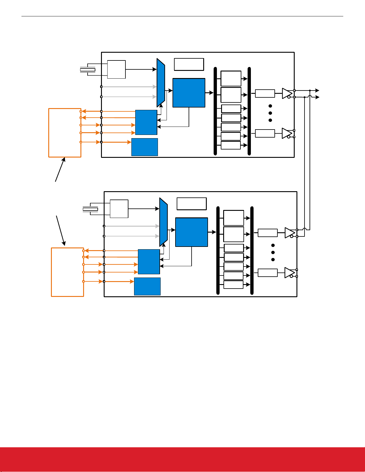
The figure above represents a use case scenario where multiple Si5332-AM devices are operated in parallel for redundancy, but without any secondary/redundant input reference clock sources. In this scenario, the primary Si5332-AM (top) can communicate an LOS
and/or FOOF signal to the MCU if a fault has been detected. The external MCU software can then decide if switching to the secondary
Si5332-AM devices is appropriate based on the fault detected and overall system safety goals. If switching to a secondary device removes the fault condition, the MCU code can signal the fault was corrected and then take appropriate system action for this case. Below is an example flowchart of the MCU software for this scenario.
silabs.com | Building a more connected world. Rev. 0.1 | 8
Page 9

Power-up
Diagnostics
pass
Enable primary
device output and
set input mux to
active input
Wait for Device
Active
Primary
device LOS
& FOOF
inactive?
Normal
Operation
on Primary
Device
Y
N
All Device
clock failure.
LOS or FOOF
assertion during
Normal Operation
on primary device
Log primary device
failure
Enable secondary
device output and
set input mux to
active input
Wait 50 ms
for PLL lock
Normal
Operation on
Secondary
Device
Y
Secondary
device LOS
& FOOF
inactive?
LOS or FOOF
assertion during
Normal Operation
on secondary device
N
AN1292: Si5332-AM SmartClock™ Fault Detection and Monitoring
System Implementation Examples Of Using Si5332-AM SmartClock Features
Figure 3.6. Example Control Software Flowchart of Redundant Si5332-AM Devices without Secondary Clock Sources
silabs.com | Building a more connected world. Rev. 0.1 | 9
Page 10
System Implementation Examples Of Using Si5332-AM SmartClock Features
3.4 Example #4 - Dual Redundant Devices with Secondary Input Clocks
Si5332-AM1/2/3 (Primary)
AN1292: Si5332-AM SmartClock™ Fault Detection and Monitoring
Can be
same
MCU
Optional Clk2
Optional Clk3
MCU
Optional Clk2
Optional Clk3
MCU
Crystal
Crystal
OSC
Reference Clocks
LOS
FOOF
CLKIN_SEL0
CLKIN_SEL1
/OE
Status /
Control
Si5332-AM1/2/3 (Secondary)
OSC
Reference Clocks
LOS
FOOF
CLKIN_SEL0
CLKIN_SEL1
/OE
Fault
Monitor
Fault
Monitor
Status /
Control
Mux
Mux
LDO
Low
Jitter
PLL
LDO
Low
Jitter
PLL
Multi
Synth
Multi
Synth
÷ INT
÷ INT
÷ INT
÷ INT
÷ INT
Multi
Synth
Multi
Synth
÷ INT
÷ INT
÷ INT
÷ INT
÷ INT
6/8/12
Output
Clocks
÷ INT
÷ INT
÷ INT
÷ INT
Figure 3.7. Redundant Si5332-AM Devices with Secondary Clock Sources
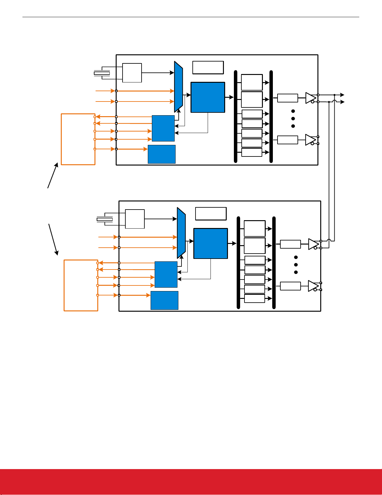
The figure above represents a use case scenario where multiple Si5332-AM devices are operated in parallel, and include secondary/
redundant reference clock sources. In this scenario the primary Si5332-AM (top) can communicate an LOS and/or FOOF signal to the
MCU if a fault has been detected on the crystal oscillator or PLL block. The external MCU software can then decide if switching to the
secondary Si5332-AM device or secondary input clock source is appropriate based on the fault detected and overall system safety
goals. If switching to a secondary device or secondary input clock source removes the fault condition, the MCU code can signal the
fault was corrected and then take appropriate system action for this case. Below is an example flowchart of the MCU software for this
scenario.
silabs.com | Building a more connected world. Rev. 0.1 | 10
Page 11

Power-up
Diagnostics
pass
Set input mux to
primary input
Wait for Device
Active
LOS &
FOOF
inactive
?
Normal
Operation
w/primary
input
Y
N
Log primary
input failure
Switch input mux
to backup input
Wait 50 ms
for PLL lock
LOS &
FOOF
inactive
?
Normal
Operation
w/secondary
input
Switch to
Secondary
Device
Y
N
LOS or FOOF
assertion during
Normal Operation
w/primary input
LOS or FOOF
assertion during
Normal Operation
w/secondary
input
Set input mux to
primary input
Wait 50 ms
for PLL lock
LOS &
FOOF
inactive
?
Normal
Operation
w/primary
input
Y
N
Log primary
input failure
Switch input mux
to backup input
Wait 50 ms
for PLL lock
LOS &
FOOF
inactive
?
Normal
Operation
w/secondary
input
All clock
failure.
Y
N
LOS or FOOF
assertion during
Normal Operation
w/primary input
LOS or FOOF
assertion during
Normal Operation
w/secondary
input
Primary Device Secondary Device
Log primary device
failure
AN1292: Si5332-AM SmartClock™ Fault Detection and Monitoring
System Implementation Examples Of Using Si5332-AM SmartClock Features
Figure 3.8. Example Control Software Flowchart of Redundant Si5332-AM devices with Secondary Clock Sources
silabs.com | Building a more connected world. Rev. 0.1 | 11
Page 12

AN1292: Si5332-AM SmartClock™ Fault Detection and Monitoring
System Implementation Examples Of Using Si5332-AM SmartClock Features
3.5 Example #5 - Dual Redundant Devices with Cross-Coupled Reference Clocks
Si5332-AM1/2/3 (Device A)
Can be
same
MCU
MCU
MCU
Crystal
Crystal
OSC
Reference Clocks
LOS
FOOF
CLKIN_SEL0
CLKIN_SEL1
OSC
Reference Clocks
LOS
FOOF
CLKIN_SEL0
CLKIN_SEL1
LDO
Multi
Synth
Multi
Synth
÷ INT
÷ INT
÷ INT
÷ INT
÷ INT
Fault
Monitor
Status /
Control
Mux
Low
Jitter
PLL
Si5332-AM1/2/3 (Device B)
LDO
Multi
Synth
Multi
Synth
÷ INT
÷ INT
÷ INT
÷ INT
÷ INT
Fault
Monitor
Status /
Control
Mux
Low
Jitter
PLL
÷ INT
÷ INT
÷ INT
÷ INT
5/7/11 Output
Clocks
}
5/7/11 Output
Clocks
}
Figure 3.9. Redundant Si5332-AM Devices with Cross-Coupled References
The figure above represents a use case scenario where multiple Si5332-AM devices are operated, with one Si5332-AM device providing the
the other SI5332-AM, reducing the total number of output reference clocks that can be used for endpoints, however this topology provides added redundancy and no other reference input clocks external to the Si5332-AM devices are required. In this scenario either
device (A or B) can communicate an LOS and/or FOOF signal to the MCU if a fault has been detected on the crystal oscillator or PLL
block. The external MCU software can then decide if switching to the other S5i332-AM device (A or B) reference clock source is appropriate based on the fault detected, and overall system safety goals. If switching to the other reference clock removes the fault condition,
the MCU code can then signal the fault was corrected and then take appropriate system action for this case. Below is an example flowchart of the MCU software for this scenario.
alternate input reference clock to the other Si5332-AM device. One output from each Si5332-AM must be used as an input to
silabs.com | Building a more connected world. Rev. 0.1 | 12
Page 13

Power-up
Diagnostics
pass
Set input mux to
primary input
Wait for Device
Active
LOS &
FOOF
inactive
?
Normal
Operation
w/primary
input
Y
N
Log primary
input failure
Switch input mux
to device A/B
input
Wait 50 ms
for PLL lock
LOS &
FOOF
inactive
?
Normal
Operation
w/secondary
input
All input
clock failure
of device A/B
Y
N
LOS or FOOF
assertion during
Normal Operation
w/primary input
LOS or FOOF
assertion during
Normal Operation
w/secondary
input
AN1292: Si5332-AM SmartClock™ Fault Detection and Monitoring
System Implementation Examples Of Using Si5332-AM SmartClock Features
Figure 3.10. Example Control Software flowchart of each Si5332-AM Device with Cross-Coupled Reference Clock Sources
The
fault condition and appropriately handle the condition.
above represents the software flow used on each Si5332 device. The MCU must keep track of which device (A or B) has the
figure
silabs.com | Building a more connected world. Rev. 0.1 | 13
Page 14

AN1292: Si5332-AM SmartClock™ Fault Detection and Monitoring
Conclusion
4. Conclusion
The Si5332-AM automotive clock generators provide numerous benefits and advantages over quartz crystals and quartz crystal oscillator based timing solutions. Si5332-AM clock generators can support up to 12 unique frequency outputs, allowing system designers to
eliminate quartz-based points of failures and greatly improving system reliability. Si5332-AM clock generators also include added features that help simplify clock tree design, including input reference health monitoring, fault detection, and recovery features that can
switch to alternate/redundant inputs in the event of fault via communication with an external MCU or system safety manager IC.
The Si5332-AM family system clocking scenarios presented in this application note are examples of how the Si5332-AM clock generator family can be used to implement different levels of health monitoring, fault detection, and intelligent recovery using SmartClock features. These example scenarios also illustrate the flexibility that is available when configuring anywhere from simple to full redundant
clocking systems. This flexibility gives the system designer the ability to use the Si5332-AM family, along with system software, to tailor
the level of fault tolerance and fault recovery necessary to meet a wide range of system safety requirements
For more information, feel free to contact us at https://www.silabs.com/support
silabs.com | Building a more connected world. Rev. 0.1 | 14
Page 15

ClockBuilder Pro
One-click access to Timing tools,
documentation, software, source
code libraries & more. Available for
Windows and iOS (CBGo only).
www.silabs.com/CBPro
Timing Portfolio
www.silabs.com/timing
SW/HW
www.silabs.com/CBPro
Quality
www.silabs.com/quality
Support and Community
community.silabs.com
http://www.silabs.com
Silicon Laboratories Inc.
400 West Cesar Chavez
Austin, TX 78701
USA
Disclaimer
Silicon Labs intends to provide customers with the latest, accurate, and in-depth documentation of all peripherals and modules available for system and software implementers using or
intending to use the Silicon Labs products. Characterization data, available modules and peripherals, memory sizes and memory addresses refer to each specific device, and "Typical"
parameters provided can and do vary in different applications. Application examples described herein are for illustrative purposes only. Silicon Labs reserves the right to make changes without
further notice to the product information, specifications, and descriptions herein, and does not give warranties as to the accuracy or completeness of the included information. Without prior
notification, Silicon Labs may update product firmware during the manufacturing process for security or reliability reasons. Such changes will not alter the specifications or the performance
of the product. Silicon Labs shall have no liability for the consequences of use of the information supplied in this document. This document does not imply or expressly grant any license
to design or fabricate any integrated circuits. The products are not designed or authorized to be used within any FDA Class III devices, applications for which FDA premarket approval is
required, or Life Support Systems without the specific written consent of Silicon Labs. A "Life Support System" is any product or system intended to support or sustain life and/or health,
which, if it fails, can be reasonably expected to result in significant personal injury or death. Silicon Labs products are not designed or authorized for military applications. Silicon Labs
products shall under no circumstances be used in weapons of mass destruction including (but not limited to) nuclear, biological or chemical weapons, or missiles capable of delivering
such weapons. Silicon Labs disclaims all express and implied warranties and shall not be responsible or liable for any injuries or damages related to use of a Silicon Labs product in such
unauthorized applications.
Trademark Information
Silicon Laboratories Inc.®, Silicon Laboratories®, Silicon Labs®, SiLabs® and the Silicon Labs logo®, Bluegiga®, Bluegiga Logo®, ClockBuilder®, CMEMS®, DSPLL®, EFM®, EFM32®,
EFR, Ember®, Energy Micro, Energy Micro logo and combinations thereof, "the world’s most energy friendly microcontrollers", Ember®, EZLink®, EZRadio®, EZRadioPRO®, Gecko®,
Gecko OS, Gecko OS Studio, ISOmodem®, Precision32®, ProSLIC®, Simplicity Studio®, SiPHY®, Telegesis, the Telegesis Logo®, USBXpress® , Zentri, the Zentri logo and Zentri DMS, ZWave®, and others are trademarks or registered trademarks of Silicon Labs. ARM, CORTEX, Cortex-M3 and THUMB are trademarks or registered trademarks of ARM Holdings. Keil is a
registered trademark of ARM Limited. Wi-Fi is a registered trademark of the Wi-Fi Alliance. All other products or brand names mentioned herein are trademarks of their respective holders.
 Loading...