

Page 1
Si53258/Si53254 数据表
8/4 输出 PCIe Gen1/2/3/4/5 时钟缓冲器
Si53258/54 是业界性能高、功耗低的汽车级 PCI Express 扇出缓冲器,适用于 PCIe Gen 1/2/3/4/5
公共时钟和/或 SRIS 应用。Si53258 和 Si53254 分别提供 8 路和 4 路 100 MHz PCIe 差分时钟输
出。所有时钟输出均符合 PCIe Gen 1/2/3/4/5 公共时钟和单独参考时钟体系结构规格。
硬件控制引脚可用于使能和禁用输出,以及为具有双输入功能的设备进行输入选择。
要详细了解 PCI Express、Silicon Labs 的完整 PCIe 产品组合、应用说明和设计工具,包括符合
PCI Express 标准的 Silicon Labs PCIe 时钟抖动工具,请访问 Silicon Labs PCI Express 学习中心。
应用:
• 信息娱乐
ADAS ECU
•
• 雷达传感器
• LiDar 传感器
主要特点
• 8/4 输出,带内部终端
• 符合 PCIe Gen 1/2/3/4/5 标准
• 汽车级 2:-40 至 +105 °C
• 内部 100 Ω 或 85 Ω 线匹配
• 出色的附加抖动性能
• 0.05 ps RMS (Gen3/4)
• 0.025 ps RMS (Gen5)
• 支持扩频,以对输入时钟进行扩频直通,实
现 EMI 降低
• 独立硬件控制引脚,用于输出使能
• 可选双输入功能,带 MUX
• 1.8–3.3 V 电源
• 无铅、符合 RoHS-6
silabs.com | Building a more connected world. Rev. 1.0
Page 2

Table of Contents
1. Features List ...............................
3
2. Ordering Guide ..............................4
3. Functional Description............................5
3.1 Functional Block Diagrams ..........................5
3.1.1 Si53258A-D01AM Functional Block Diagram ..................5
3.1.2 Si53254A-D01AM Functional Block Diagram ..................5
3.1.3 Si53258A-D02AM Functional Block Diagram ..................6
3.1.4 Si53254A-D02AM Functional Block Diagram ..................6
3.2 HCSL Differential Output Terminations ......................7
3.3 Output Enable/Disable ...........................7
3.4 Loss of Signal (LOS) ............................7
4. Power Supply Filtering Recommendations ....................8
5. Electrical Specifications ...........................9
6. Pin Descriptions .............................14
6.1 Si53258A-D01AM Pin Descriptions (40-QFN) ...................14
6.2 Si53258A-D02AM Pin Descriptions (40-QFN) ...................18
6.3 Si53254A-D01AM Pin Descriptions (32-QFN) ...................22
6.4 Si53254A-D02AM Pin Descriptions (40-QFN) ...................25
7. Package Outline .............................29
7.1 6x6 mm 40-QFN Package Diagram .......................29
7.2 5x5 mm 32-QFN Package Diagram .......................31
8. PCB Land Pattern ............................33
8.1 40-QFN Land Pattern............................33
8.2 32-QFN Land Pattern............................35
9. Top Marking ............................... 37
10. Revision History............................. 38
silabs.com | Building a more connected world. Rev. 1.0 | 2
Page 3

1. 功能列表
• 8/4-HCSL 输出,带内部终端
• 符合 PCIe Gen1/2/3/4/5 标准
• 汽车级 2:-40 至 +105 °C
• 内部 100 Ω 或 85 Ω 线匹配
• 出色的附加抖动性能
•
0.05 ps RMS (Gen3/4)
•
0.025 ps RMS (Gen5)
• 支持扩频,以对输入时钟进行扩频直通,实现 EMI 降低
• 信号丢失 (LOS) 输出引脚
• 独立硬件控制引脚,用于输出使能
• 可选双输入功能,带 MUX
• 1.8–3.3 V 电源
• 无铅、符合 RoHS-6
Si53258/Si53254 数据表
功能列表
silabs.com | Building a more connected world. Rev. 1.0 | 3
Page 4
2. Ordering Guide
Si53258/Si53254 Data Sheet
Ordering Guide
Number of
Outputs
8
4
Number of
Inputs
1
2
1
2
Part Number Package Type Temperature
Si53258A-D01AM 40-QFN
Si53258A-D01AMR 40-QFN, Tape and Reel
Si53258A-D02AM 40-QFN
Si53258A-D02AMR 40-QFN, Tape and Reel
Automotive, –40 to 105 °C
Si53254A-D01AM 32-QFN
Si53254A-D01AMR 32-QFN, Tape and Reel
Si53254A-D02AM 40-QFN
Si53254A-D02AMR 40-QFN, Tape and Reel
silabs.com | Building a more connected world. Rev. 1.0 | 4
Page 5
3. Functional Description
3.1 Functional Block Diagrams
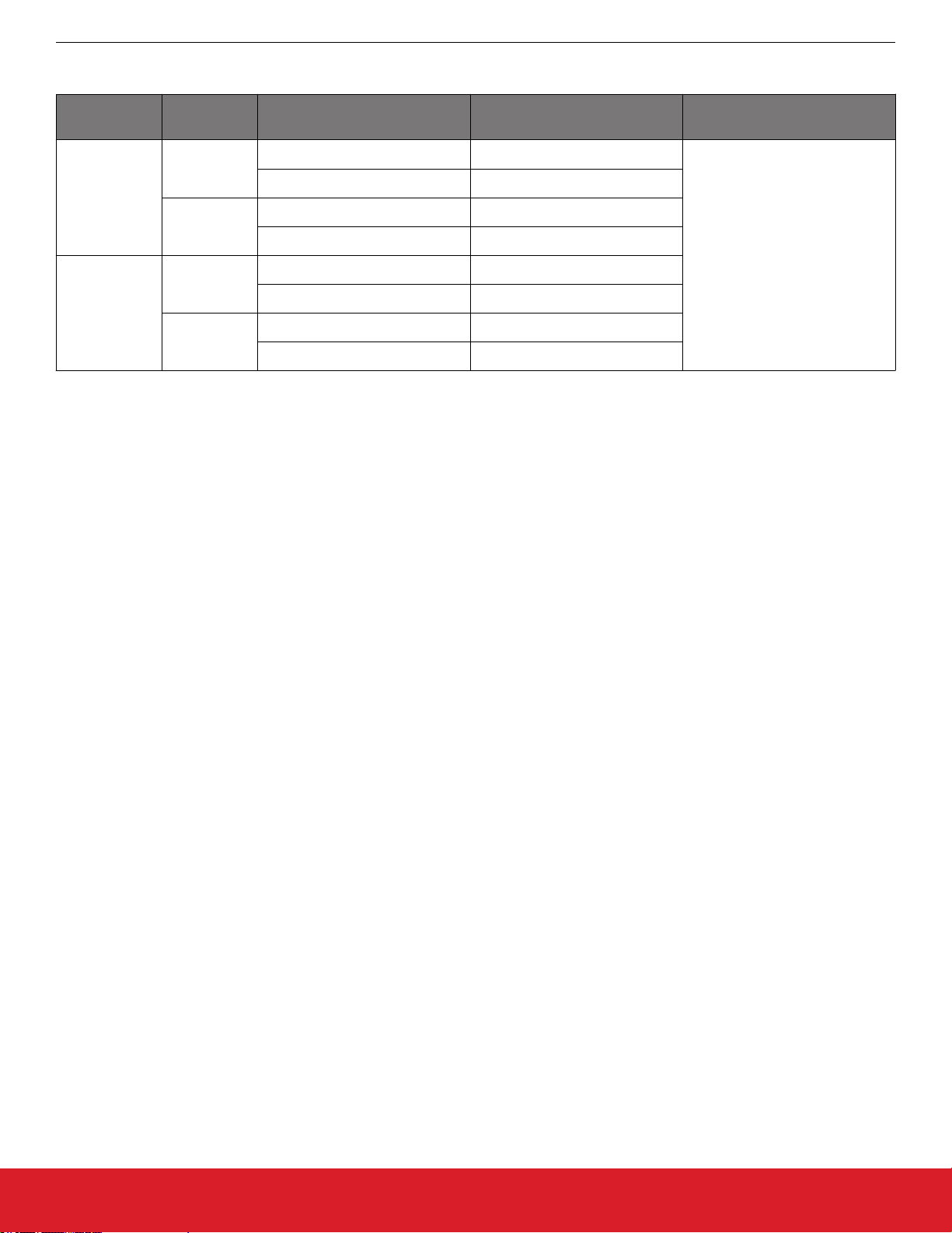
3.1.1 Si53258A-D01AM Functional Block Diagram
Si53258/Si53254 Data Sheet
Functional Description
OE1:0
OUT0
OUT1
OE2
OUT2
CLKIN
IMP_SEL
LOS
Figure 3.1. Si53258A-D01AM Functional Block Diagram
3.1.2 Si53254A-D01AM Functional Block Diagram
Control
OE3
OUT3
OE4
OUT4
OE5
OUT5
OE6
OUT6
OE7
OUT7
OE1:0
OUT0
OUT1
CLKIN
OE2
OUT2
IMP_SEL
LOS
Control
OE3
OUT3
Figure 3.2. SSi53254A-D01AM Functional Block Diagram
silabs.com | Building a more connected world. Rev. 1.0 | 5
Page 6
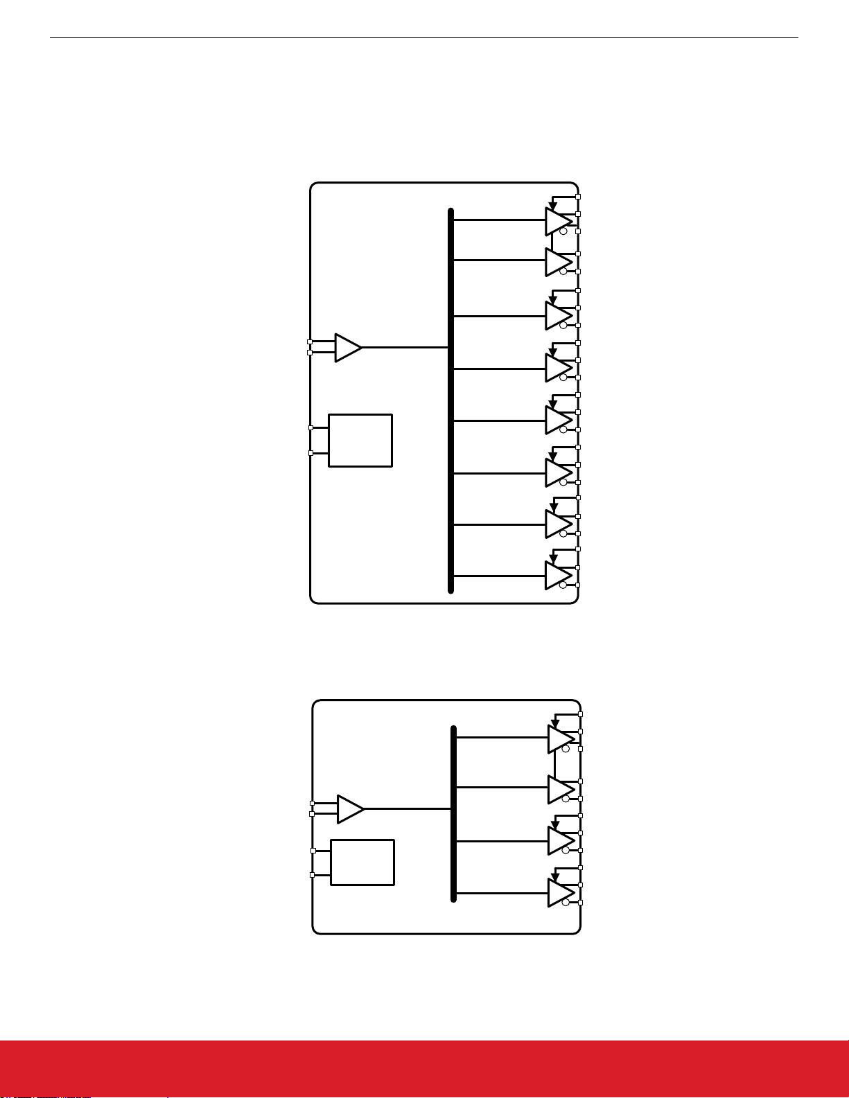
3.1.3 Si53258A-D02AM Functional Block Diagram
Si53258/Si53254 Data Sheet
Functional Description
OE1:0
OUT0
OUT1
OE3:2
CLKIN1
CLKIN2
SEL
IMP_SEL
Control
LOS
Figure 3.3. Si53258A-D02AM Functional Block Diagram
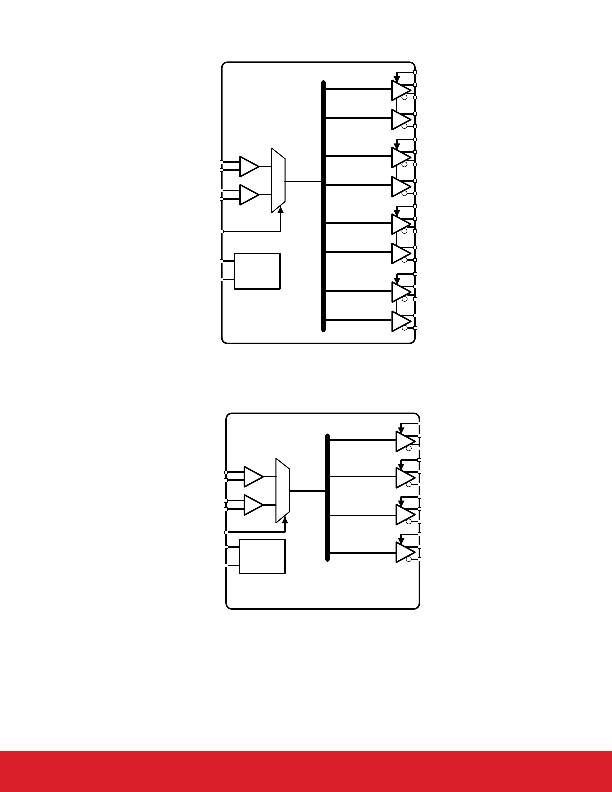
3.1.4 Si53254A-D02AM Functional Block Diagram
OUT2
OUT3
OE5:4
OUT4
OUT5
OE7:6
OUT6
OUT7
OE0
OUT0
CLKIN1
CLKIN2
CLK_SEL
IMP_SEL
Control
LOS
Figure 3.4. Si53254A-D02AM Functional Block Diagram
OE1
OUT1
OE2
OUT2
OE3
OUT3
silabs.com | Building a more connected world. Rev. 1.0 | 6
Page 7
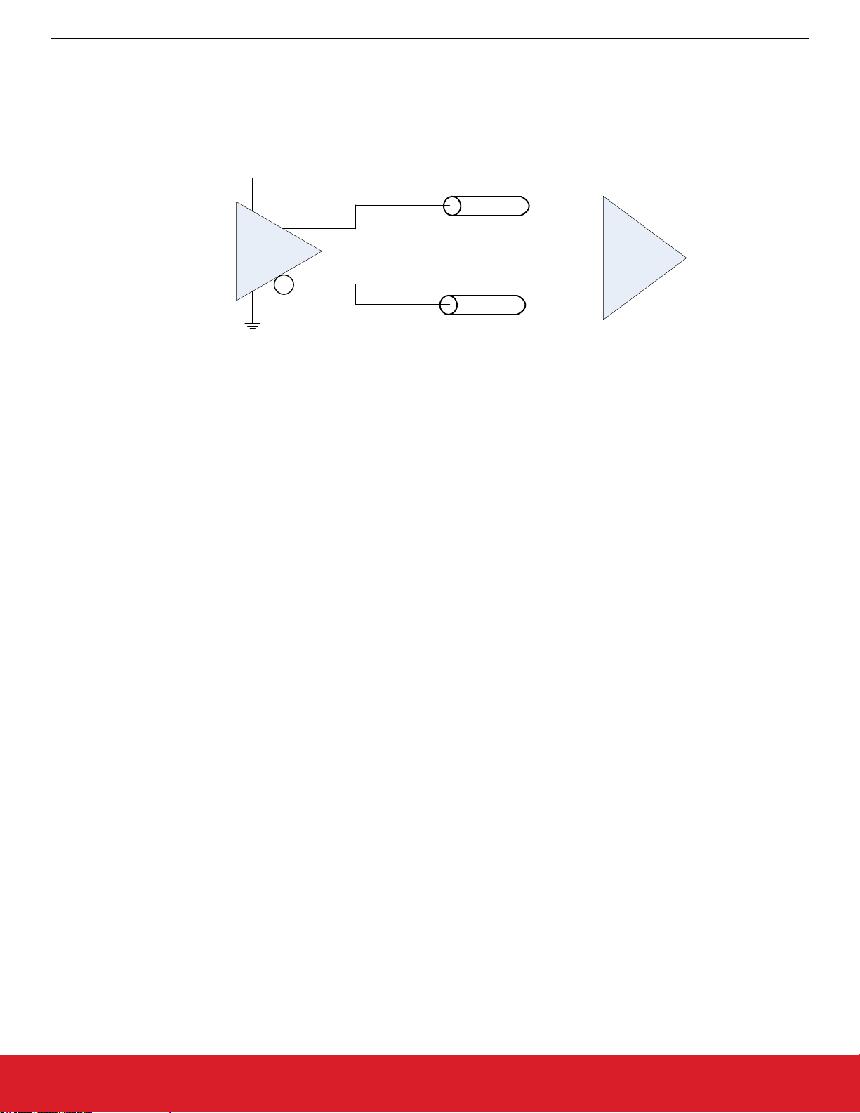
3.2 HCSL Differential Output Terminations
Termination for HCSL Outputs
Si53258/Si53254 Data Sheet
Functional Description
The Si52254/8
ports both 100 Ω and 85 Ω transmission line options, and can be selected using the IMP_SEL hardware input pin.
HCSL driver features integrated termination resistors to simplify interfacing to an HCSL receiver. The HCSL driver sup-
1.71 V to 3.465 V
Zo = 42.5 Ω or 50 Ω
OUTx
HCSL Output
Driv
er
HCSL
Receiver
Zo = 42.5 Ω or 50 Ω
OUTxb
Figure 3.5. HCSL Internal Termination Mode
3.3 Output Enable/Disable
An output
all designated outputs will be disabled. When held low, the designated outputs will be enabled.
3.4 Loss of Signal (LOS)
The LOS indicator is used to check for the presence of an input reference source (crystal or clock). LOS will assert when the reference
source frequency drops below approximately 10 MHz.
enable pin provides a convenient method of disabling or enabling the output drivers. When the output enable pin is held high,
The LOS pin must be checked prior to selecting the clock input or should be polled to check for the presence of the currently selected
input clock. In the event that a reference source is not present, the associated LOS pin will assume a logic low (LOS = 0) state. When a
reference source is present at the associated input clock pin, the LOS pin will assume a logic high (LOS = 1) state.
silabs.com | Building a more connected world. Rev. 1.0 | 7
Page 8

Si53258/Si53254 Data Sheet
Power Supply Filtering Recommendations
4. Power Supply Filtering Recommendations
The Si53258/4 features internal LDOs on each power supply pin, providing excellent power supply noise rejection. As a guideline, each
power supply pin should use a parallel combination of a 1 μf and a 0.1 μF bypass capacitor placed as close to the supply pin as possible.
silabs.com | Building a more connected world. Rev. 1.0 | 8
Page 9
5. Electrical Specifications
Si53258/Si53254 Data Sheet
Electrical Specifications
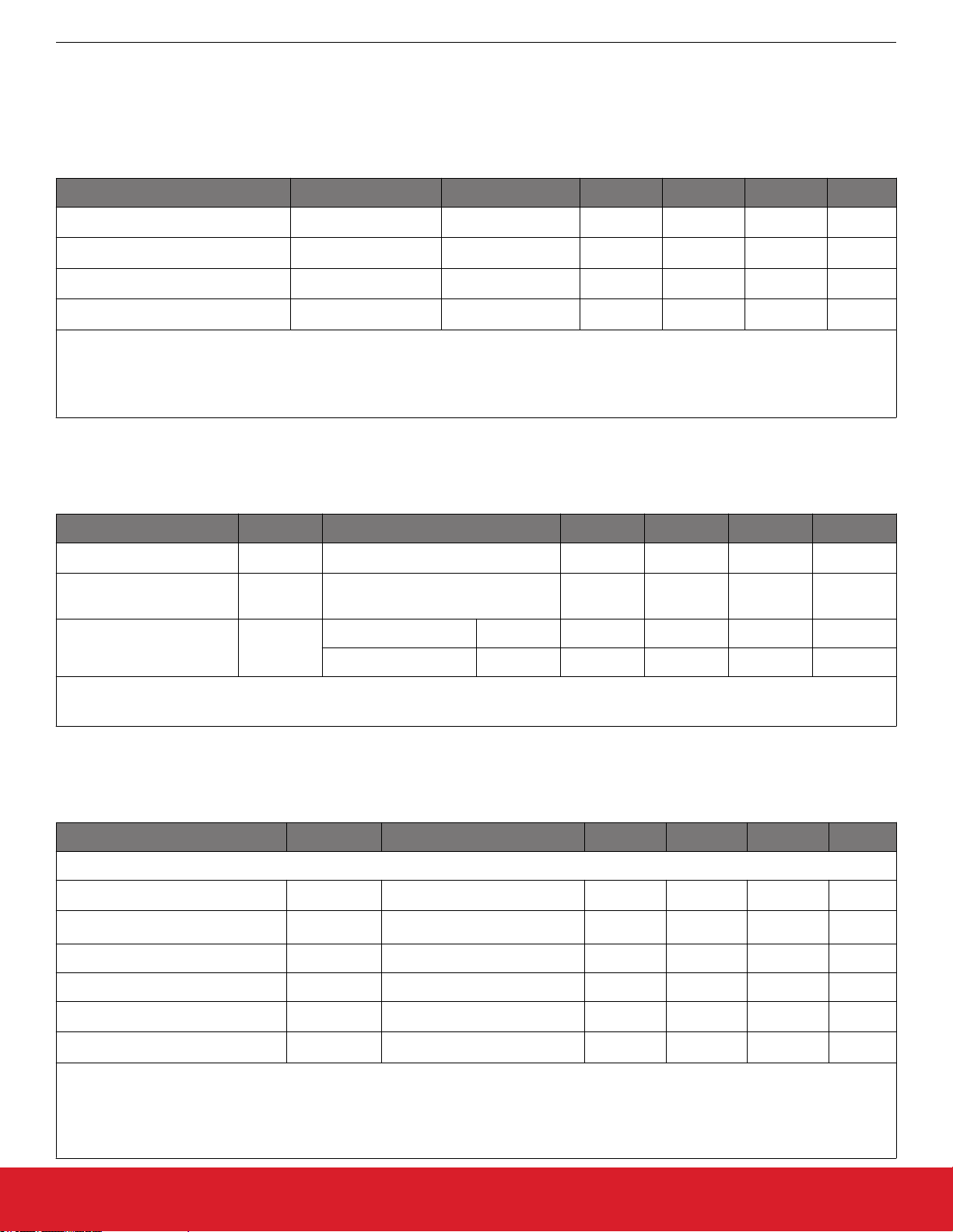
Table 5.1. Recommended Operating Conditions
(VDD = V
DDA
= V
= 1.8 V to 3.3 V +5%/-5%, V
DD_DIG
= 1.8 V ±5%, 2.5 V ±5%, or 3.3 V ±5%, TA = –40 to 105 °C)
DDO
Parameter Symbol Test Condition Min Typ Max Units
DDA
TJ
, V
T
A
MAX
DD_DIG
V
DDO
, V
DD
–40 25 105 °C
— — 125 °C
1.71 — 3.46 V
1.42
2
— 3.46 V
Ambient Temperature
Junction Temperature
Core Supply Voltage
Output Driver Supply Voltage
V
Note:
All minimum and maximum specifications are guaranteed and apply across the recommended operating conditions. Typical val-
1.
ues apply at nominal supply voltages and an operating temperature of 25 °C unless otherwise noted.
2.
LVCMOS outputs only.
Table 5.2. DC Characteristics
(VDD = V
DDA
= V
= 1.8 V to 3.3 V +5%/-5%, V
DD_DIG
= 1.8 V ±5%, 2.5 V ±5%, or 3.3 V ±5%, TA = –40 to 105 °C)
DDO
Parameter Symbol Test Condition Min Typ Max Units
Core Supply Current
Output Buffer Supply Current
I
DD
I
DDOx
HCSL Output1 @ 100 MHz
— 11 18 mA
— 20 22 mA
Total Power Dissipation
P
d
32-pin — 145 215 mW
Notes:
40-pin 530 670 mW
Differential outputs terminated into a 100
1.
Ω load at 3.3 V.
Table 5.3. Clock Input Specifications
(VDD = V
DDA
= V
= 1.8 V to 3.3 V +5%/-5%, V
DD_DIG
= 1.8 V ±5%, 2.5 V ±5%, or 3.3 V ±5%, TA = –40 to 105 °C)
DDO
Parameter Symbol Test Condition Min Typ Max Units
Input Clock (AC-coupled Differential Input Clock on CLKIN_2/CLKIN_2# or CLKIN_3/CLKIN_3#)
Frequency F
Voltage Swing
V
PP_DIFF
IN
3
Differential — 100 — MHz
0.5 — 1.8 V
PP_diff
Slew Rate SR/SF 20-80% 0.75 — — V/ns
Duty Cycle DC 40 — 60 %
Input Impedance R
Input Capacitance C
IN
IN
10 — — kΩ
2 3.5 6 pF
Notes:
1.
Imposed for jitter performance.
Rise and fall times can be estimated using the following simplified equation: tr/tf
2.
3. V
PP_DIFF
= 2 x V
PP_SINGLE-ENDED
= ((0.8 - 0.2) * V
80-20
IN_Vpp_se
) / SR.
silabs.com | Building a more connected world. Rev. 1.0 | 9
Page 10
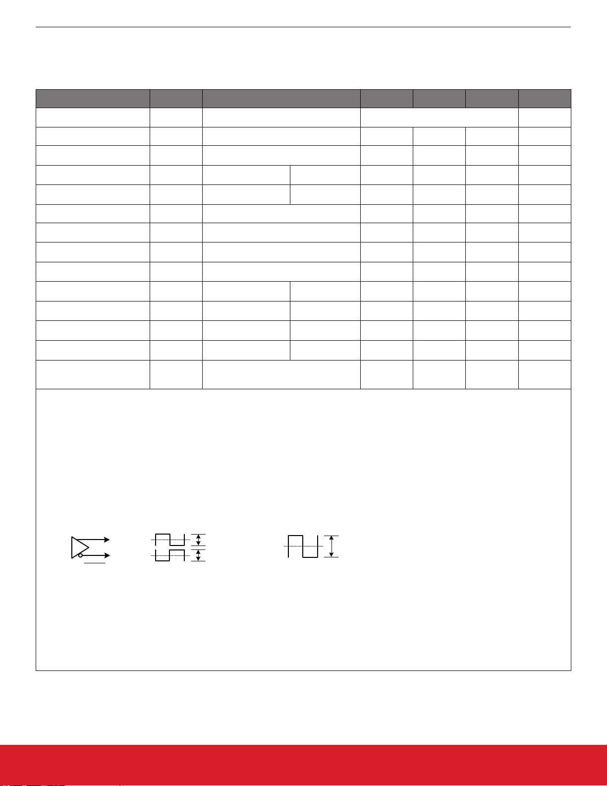
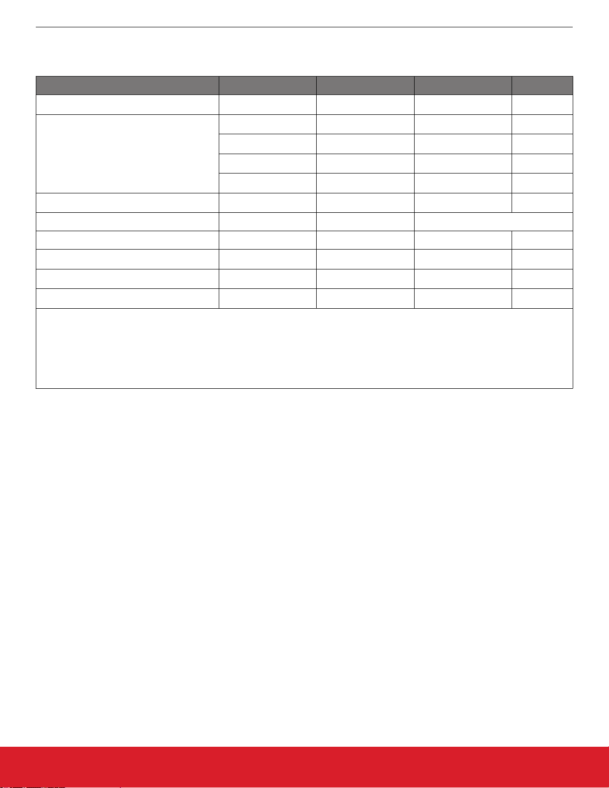
Table 5.4. Differential Clock Output Specifications
Si53258/Si53254 Data Sheet
Electrical Specifications
(VDD = V
DDA
= V
= 1.8 V to 3.3 V +5%/-5%, V
DD_DIG
= 1.8 V ±5%, 2.5 V ±5%, or 3.3 V ±5%, TA = –40 to 105 °C)
DDO
Parameter Symbol Test Condition Min Typ Max Units
Output Frequency
f
OUT
100 MHz
Duty Cycle DC With 50% duty cycle input. 48 — 52 %
V
V
T
SK
SEPP
CM
— — 80 ps
HCSL 0.7 0.8 0.9
V
HCSL 0.35 0.4 0.45 V
Output-Output Skew
Output Voltage Swing
Common Mode Voltage
HCSL Edge Rate Edgr Notes 1, 2, 3 1 — 4.5 V/ns
HCSL Delta Tr
HCSL Delta Tf
HCSL Vcross Abs
HCSL Delta Vcross
HCSL Vovs
HCSL Vuds
HCSL Vrng
D
tr
D
tf
V
xa
D
vcrs
V
ovs
V
uds
V
rng
Notes 2, 4, 8 — — 140 mV
Notes 2, 4, 9 — —
Notes 2, 4, 10 — —
Notes 2, 4
Notes 2, 4, 5 — — 155 ps
Notes 2, 4, 5 — — 155 ps
Notes 6, 7, 2, 4 250 — 550 mV
V
V
HIGH
-200
—
V
V
HIGH
LOW
LOW
+300
-300
+200
mV
mV
mV
PP
Rise and Fall Times
(20% to 80%)
tR/t
F
HCSL — — 420 ps
Notes:
Measure taken from differential waveform on a component test board. The edge (slew) rate is measured from –150 mV to +150
1.
mV on the differential waveform . Scope is set to average because the scope sample clock is making most of the dynamic wiggles along the clock edge Only valid for Rising clock and Falling Clock#. Signal must be monotonic through the Vol to Voh region
for Trise and Tfall.
Applies to a 2 pf load with both internal or external 50 Ω or 42.5 Ω Rp.
2.
3. Measurement taken from differential waveform.
4. Measurement taken from Single Ended waveform.
5. Measured with oscilloscope, averaging off, using min max statistics. Variation is the delta between min and max.
OUTx
Vcm
Vcm
OUTx
Vpp_se
Vpp_se
Vcm
Vpp_diff = 2*Vpp_se
6. Measured at crossing point where the instantaneous voltage value of the rising edge of CLK equals the falling edge of CLK#.
7. This measurement refers to the total variation from the lowest crossing point to the highest, regardless of which edge is crossing.
ΔVcross is defined as the total variation of all crossing voltages of Rising CLOCK and Falling CLOCK#. This is the maximum
8.
allowed variance in Vcross for any particular system.
9. Overshoot is defined as the absolute value of the maximum voltage.
10. Undershoot is defined as the absolute value of the minimum voltage.
silabs.com | Building a more connected world. Rev. 1.0 | 10
Page 11
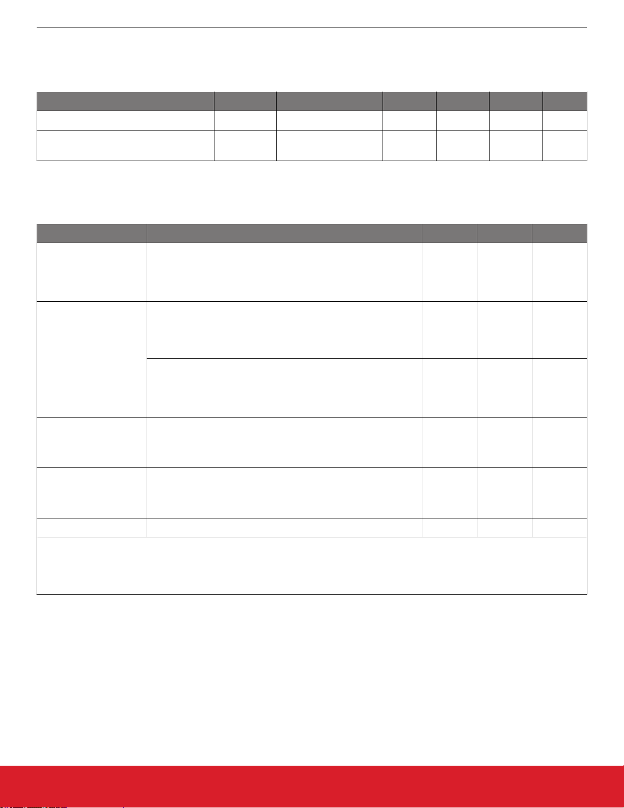
Table 5.5. Performance Characteristics
Si53258/Si53254 Data Sheet
Electrical Specifications
(VDD = V
DDA
= V
= 1.8 V to 3.3 V +5%/-5%, V
DD_DIG
= 1.8 V ±5%, 2.5 V ±5%, or 3.3 V ±5%, TA = –40 to 105 °C)
DDO
Parameter Symbol Test Condition Min Typ Max Units
Power Ramp
Clock Stabilization from Power-up
t
VDD
t
STABLE
0 V to V
DDmin
Time for clock outputs to
appear after POR
0.1 — 10 ms
— 15 25 ms
Table 5.6. PCI-Express Clock Output Additive Phase Jitter (100 MHz)
(VDD = V
DDA
= V
= 1.8 V to 3.3 V +5%/-5%, V
DD_DIG
= 1.8 V ±5%, 2.5 V ±5%, or 3.3 V ±5%, TA = –40 to 85 °C)
DDO
Parameter Test Condition Typ Max Units
Includes PLL BW 1.5–22 MHz,
PCIe Gen 1.1
Peaking = 3 dB, Td = 10 ns,
Ftrk = 1.5 MHz with BER = 1E-12
1
11 19 ps RMS
Includes PLL BW 5MHz and 8–16 MHz,
Jitter Peaking = 0.01–1 dB and 3 dB,
0.02 0.026 ps RMS
Td=12ns, Low Band, F < 1.5 MHz
PCIe Gen 2.1
Includes PLL BW 5 MHz and 8–16 MHz,
Jitter Peaking = 0.01–1 dB and 3 dB,
Td = 12 ns, High Band, 1.5 MHz < F < Nyquist
1
0.2 0.31 ps RMS
Includes PLL BW 2–4 MHz and 5 MHz, Peaking = 0.01–2 dB and
PCIe Gen 3.0
1 dB,
Td = 12 ns, CDR = 10 MHz
1, 2
0.06 0.1 ps RMS
Includes PLL BW 2–4 MHz and 5 MHz, Peaking = 0.01–2 dB and
PCIe Gen 4.0
Td = 12 ns, CDR = 10 MHz
1dB,
0.05 0.1 ps RMS
1
,
2
PCIe Gen5.0 0.025 0.04 ps RMS
Note:
1.
All output clocks 100 MHz HCSL format. Jitter data taken from Clock Jitter Tool v.1.3.
2. Excludes oscilloscope sampling noise.
silabs.com | Building a more connected world. Rev. 1.0 | 11
Page 12
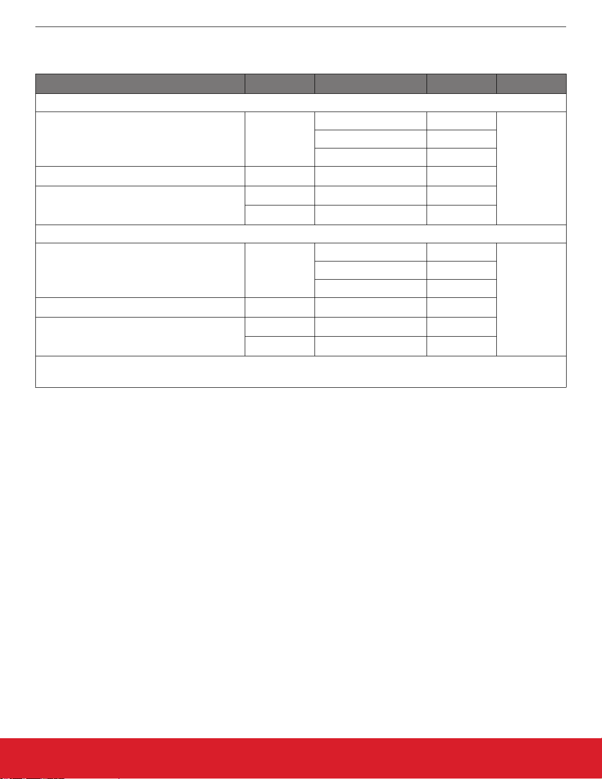
Table 5.7. Thermal Characteristics
Si53258/Si53254 Data Sheet
Electrical Specifications
Parameter Symbol
40 QFN
Thermal Resistance, Junction to Ambient
Thermal Resistance, Junction to Case
Thermal Resistance, Junction to Board
32 QFN
Thermal Resistance, Junction to Ambient
Thermal Resistance, Junction to Case
Thermal Resistance, Junction to Board
Note:
Based on JEDEC standard 4-layer PCB.
1.
Test Condition
1
Value Units
Still Air 23.1
θ
JA
Air Flow 1 m/s 17.5
Air Flow 2 m/s 16.5
θ
JC
θ
JB
ψ
JB
13.4
8.7
8.4
°C/W
Still Air 28.4
θ
JA
Air Flow 1 m/s 24
Air Flow 2 m/s 23
θ
JC
θ
JB
ψ
JB
15.9
11.5
11.2
°C/W
silabs.com | Building a more connected world. Rev. 1.0 | 12
Page 13
Si53258/Si53254 Data Sheet
Electrical Specifications
Table 5.8. Absolute Maximum Ratings
1,2,3
Parameter Symbol Test Condition Value Units
V
T
V
STG
DD
DDA
–55 to +150 °C
–0.5 to 3.8 V
–0.5 to 3.8 V
Storage Temperature Range
DC Supply Voltage
Input Voltage Range
VDD
V
DDO
xtal
V
I
–0.5 to 3.8 V
–0.5 to 3.8 V
–0.3 to 1.3 V
Latch-up Tolerance LU JESD78 Compliant
ESD Tolerance HBM 100 pF, 1.5 kΩ 2.0 kV
Junction Temperature
Soldering Temperature
Soldering Temperature Time at T
PEAK
T
T
PEAK
JCT
T
–55 to 125 °C
260 °C
P
20 to 40 sec
Notes:
Permanent device damage may occur if the absolute maximum ratings are exceeded. Functional operation should be restricted to
1.
the conditions as specified in the operational sections of this data sheet. Exposure to absolute maximum rating conditions for extended periods may affect device reliability.
2.
For more packaging information, go to www.silabs.com/support/quality/pages/RoHSInformation.aspx.
3. The device is compliant with JEDEC J-STD-020.
silabs.com | Building a more connected world. Rev. 1.0 | 13
Page 14

6. Pin Descriptions
6.1 Si53258A-D01AM Pin Descriptions (40-QFN)
Si53258/Si53254 Data Sheet
Pin Descriptions
VDD_DIG
CLK_IN1
CLK_IN1b
VDD
NC
NC
OEb_OUT1:0
OEb_OUT2
VDDA
LOS
10
OEb_OUT7
37
Ground
14
OUT0
OEb_OUT6
OUT6
36
35
41
15
16
OUT1b
VDDO0
OUT7b
OUT7
VDDO5
40
39
38
1
2
3
4
5
6
7
8
9
11
12
13
GND
GND
OUT0b
OUT6b
34
17
OUT1
VDDO4
33
18
VDDO1
OEb_OUT4
OEb_OUT5
32
19
20 31
IMP_SEL
OEb_OUT3
30
27
26
23
22
29
28
25
24
21
OUT5
OUT5b
VDDO3
OUT4
OUT4b
VDDO2
OUT3
OUT3b
OUT2
OUT2b
Figure 6.1. Si53258A-D01AM 40-QFN
silabs.com | Building a more connected world. Rev. 1.0 | 14
Page 15

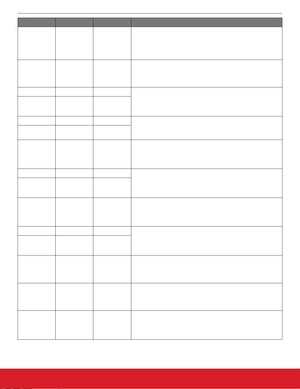
Table 6.1. Si53258A-D01AM Pin Descriptions (40-QFN)
Pin Number Pin Name Pin Type Function
Si53258/Si53254 Data Sheet
Pin Descriptions
1 VDD_DIG P
2 CLK_IN1 I
3 CLK_IN1b I
4 VDD P
5 NC I
6 NC I
7 OEb_OUT1:0 I
8 OEb_OUT2 I
9 VDDA P
10 LOS O
Voltage supply for digital functions. Connect to 1.8–3.3 V. Part of internal
core VDD voltage. Must be connected to same voltage as VDDA and VDD.
100 MHz HCSL Clock1 input. These pins are high-impedance and must be
terminated externally.
Voltage supply. Connect to 1.8–3.3 V. Part of internal core VDD voltage.
Must be connected to same voltage as VDDA and VDD_DIG.
Do not connect these pins to anything.
Output enable pin for OUT1 and OUT0.
Low = output enabled
High = output disabled
Output enable pin for OUT2.
Low = output enabled
High = output disabled
Core Supply Voltage. Connect to 1.8–3.3 V.
Must be connected to same voltage as VDD_DIG and VDD.
The LOS status pin indicates whether the reference input has dropped below approximately 10 MHz. LOS is active low, open drain output and requires an external pull-up resistor of 1 to 10 k
Ω
for proper operation. If LOS
is not required, this pin can be left unconnected.
0 = reference input has dropped below approx. 10 MHz
1 = reference input is present (>10 MHz)
11 GND P
Connect these pins to ground.
12 GND P
13 OUT0b O Output Clock
100 MHz HCSL output. Termination recommendations are provided in
14 OUT0 O
3.2 HCSL Differential Output Terminations. Unused outputs should be left
unconnected.
Supply Voltage (1.8–3.3 V) for OUT0
15 VDDO0 P
Leave VDDOx pins of unused output drivers unconnected. An alternate option is to connect the VDDOx pin to a power supply and disable the output
driver to minimize current consumption.
16 OUT1b O Output Clock
100 MHz HCSL output. Termination recommendations are provided in
17 OUT1 O
3.2 HCSL Differential Output Terminations. Unused outputs should be left
unconnected.
Supply Voltage (1.8–3.3 V) for OUT1
18 VDDO1 P
Leave VDDOx pins of unused output drivers unconnected. An alternate option is to connect the VDDOx pin to a power supply and disable the output
driver to minimize current consumption.
silabs.com | Building a more connected world. Rev. 1.0 | 15
Page 16
Pin Number Pin Name Pin Type Function
Impedance select pin for output drivers. IMP_SEL pin is sampled at powerup only.
19 IMP_SEL I
Low = 100 Ω
High = 85 Ω
Output enable pin for OUT3.
Si53258/Si53254 Data Sheet
Pin Descriptions
20 OEb_OUT3 I
Low = output enabled
High = output disabled
21 OUT2b O Output Clock
100 MHz HCSL output. Termination recommendations are provided in
22 OUT2 O
3.2 HCSL Differential Output Terminations. Unused outputs should be left
unconnected.
23 OUT3b O Output Clock
24 OUT3 O
Termination recommendations are provided in 3.2 HCSL Differential Output
Terminations. Unused outputs should be left unconnected.
Supply Voltage (1.8–3.3 V) for OUT2 and OUT3
25 VDDO2 P
Leave VDDOx pins of unused output drivers unconnected. An alternate option is to connect the VDDOx pin to a power supply and disable the output
driver to minimize current consumption.
26 OUT4b O Output Clock
100 MHz HCSL output. Termination recommendations are provided in
27 OUT4 O
3.2 HCSL Differential Output Terminations. Unused outputs should be left
unconnected.
Supply Voltage (1.8–3.3 V) for OUT4 and OUT5
28 VDDO3 P
Leave VDDOx pins of unused output drivers unconnected. An alternate option is to connect the VDDOx pin to a power supply and disable the output
driver to minimize current consumption.
29 OUT5b O Output Clock
100 MHz HCSL output. Termination recommendations are provided in
30 OUT5 O
3.2 HCSL Differential Output Terminations. Unused outputs should be left
unconnected.
Output enable pin for OUT4.
31 OEb_OUT4 I
Low = output enabled
High = output disabled
Output enable pin for OUT5.
32 OEb_OUT5 I
Low = output enabled
High = output disabled
Supply Voltage (1.8–3.3 V) for OUT6
33 VDDO4 P
Leave VDDOx pins of unused output drivers unconnected. An alternate option is to connect the VDDOx pin to a power supply and disable the output
driver to minimize current consumption.
silabs.com | Building a more connected world. Rev. 1.0 | 16
Page 17

Pin Number Pin Name Pin Type Function
34 OUT6b O Output Clock
100 MHz HCSL output. Termination recommendations are provided in
35 OUT6 O
3.2 HCSL Differential Output Terminations. Unused outputs should be left
unconnected.
Output enable pin for OUT6.
Si53258/Si53254 Data Sheet
Pin Descriptions
36 OEb_OUT6 I
Low = output enabled
High = output disabled
Output enable pin for OUT7.
37 OEb_OUT7 I
Low = output enabled
High = output disabled
38 OUT7b O Output Clock
100 MHz HCSL output. Termination recommendations are provided in
39 OUT7 O
3.2 HCSL Differential Output Terminations. Unused outputs should be left
unconnected.
Supply Voltage (1.8–3.3 V) for OUT7
40 VDDO5 P
Leave VDDOx pins of unused output drivers unconnected. An alternate option is to connect the VDDOx pin to a power supply and disable the output
driver to minimize current consumption.
Ground Pad
41 GND PAD P
This pad provides electrical and thermal connection to ground and must be
connected for proper operation.
silabs.com | Building a more connected world. Rev. 1.0 | 17
Page 18

6.2 Si53258A-D02AM Pin Descriptions (40-QFN)
Si53258/Si53254 Data Sheet
Pin Descriptions
VDD_DIG
CLK_IN1
CLK_IN1b
VDD
NC
NC
CLK_IN2
CLK_IN2b
VDDA
LOS
10
VDDO5
OUT7
OUT7b
40
39
38
1
2
3
4
5
6
7
8
9
11
12
13
GND
GND
OUT0b
OEb[7:6]
37
36
Ground
14
15
OUT0
OEb[5:4]
OUT6
35
41
16
OUT1b
VDDO0
OUT6b
34
17
OUT1
VDDO4
33
18
VDDO1
OEb[1:0]
OEb[3:2]
32
19
20 31
IMP_SEL
CLK_SEL
30
27
26
23
22
29
28
25
24
21
OUT5
OUT5b
VDDO3
OUT4
OUT4b
VDDO2
OUT3
OUT3b
OUT2
OUT2b
Figure 6.2. Si53258A-D02-AM 40-QFN
silabs.com | Building a more connected world. Rev. 1.0 | 18
Page 19

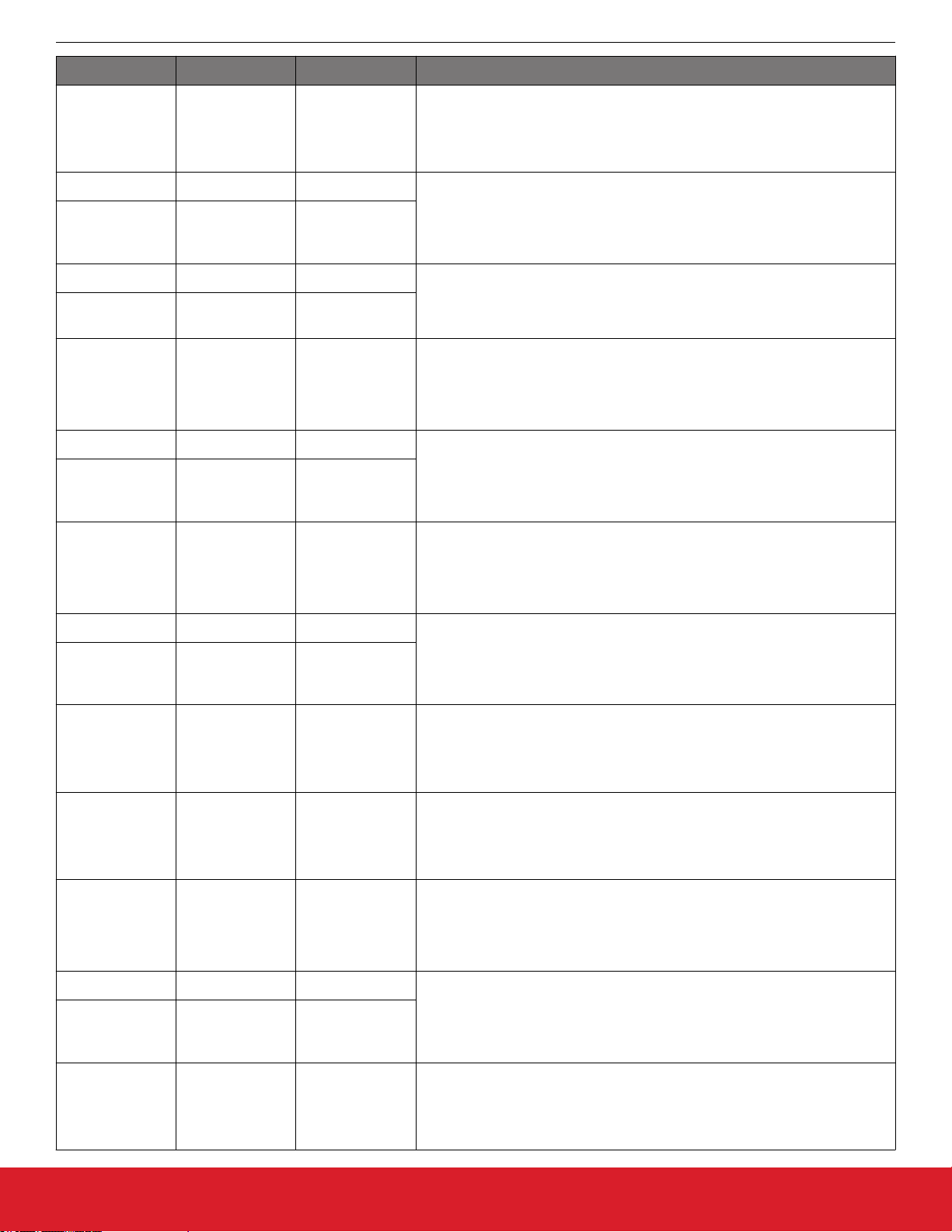
Table 6.2. Si53258A-D02AM Pin Descriptions (40-QFN)
Pin Number Pin Name Pin Type Function
Si53258/Si53254 Data Sheet
Pin Descriptions
1 VDD_DIG P
Voltage supply for digital functions. Connect to 1.8–3.3 V. Part of internal
core VDD voltage. Must be connected to same voltage as VDDA.
2 CLK_IN1 I 100 MHz HCSL Clock1 input. These pins are high-impedance and must be
terminated externally. If both the CLK_IN1 and CLK_IN1b inputs are un-
3 CLK_IN1b I
4 VDD P
used and deselected, then both inputs can be left floating.
Voltage supply. Connect to 1.8–3.3 V. Part of internal core VDD voltage.
Must be connected to same voltage as VDDA and VDD_DIG.
5 NC I
Do not connect these pins to anything.
6 NC I
7 CLK_IN2 I 100 MHz HCSL Clock2 input. These pins are high-impedance and must be
terminated externally. If both the CLK_IN2 and CLK_IN2b inputs are un-
8 CLK_IN2b I
used and deselected, then both inputs can be left floating.
Core Supply Voltage. Connect to 1.8–3.3 V.
9 VDDA P
Must be connected to same voltage as VDD_DIG and VDD.
The LOS status pin indicates whether the reference input has dropped below approximately 10 MHz. LOS is active low, open drain output and re-
for proper operation. If LOS
10 LOS O
quires an external pull-up resistor of 1 to 10 kΩ
is not required, this pin can be left unconnected.
0 = reference input has dropped below approx. 10 MHz
1 = reference input is present (>10 MHz)
11 GND P Connect this pin to ground.
12 GND P Connect this pin to ground.
13 OUT0b O Output Clock
100 MHz HCSL output. Termination recommendations are provided in
14 OUT0 O
3.2 HCSL Differential Output Terminations. Unused outputs should be left
unconnected.
Supply Voltage (1.8–3.3 V) for OUT0
15 VDDO0 P
Leave VDDOx pins of unused output drivers unconnected. An alternate option is to connect the VDDOx pin to a power supply and disable the output
driver to minimize current consumption.
16 OUT1b O Output Clock
100 MHz HCSL output. Termination recommendations are provided in
17 OUT1 O
3.2 HCSL Differential Output Terminations. Unused outputs should be left
unconnected.
Supply Voltage (1.8–3.3 V) for OUT1
18 VDDO1 P
Leave VDDOx pins of unused output drivers unconnected. An alternate option is to connect the VDDOx pin to a power supply and disable the output
driver to minimize current consumption.
Impedance select pin for output drivers. IMP_SEL pin is sampled at powerup only.
19 IMP_SEL I
Low = 100 Ω
High = 85 Ω
silabs.com | Building a more connected world. Rev. 1.0 | 19
Page 20
Pin Number Pin Name Pin Type Function
Input clock select.
Si53258/Si53254 Data Sheet
Pin Descriptions
20 CLK_SEL I
Low = CLK_IN1
High = CLK_IN2
21 OUT2b O Output Clock
100 MHz HCSL output. Termination recommendations are provided in
22 OUT2 O
3.2 HCSL Differential Output Terminations. Unused outputs should be left
unconnected.
23 OUT3b O Output Clock
24 OUT3 O
Termination recommendations are provided in 3.2 HCSL Differential Output
Terminations. Unused outputs should be left unconnected.
Supply Voltage (1.8–3.3 V) for OUT2 and OUT3
25 VDDO2 P
Leave VDDOx pins of unused output drivers unconnected. An alternate option is to connect the VDDOx pin to a power supply and disable the output
driver to minimize current consumption.
26 OUT4b O Output Clock
100 MHz HCSL output. Termination recommendations are provided in
27 OUT4 O
3.2 HCSL Differential Output Terminations. Unused outputs should be left
unconnected.
Supply Voltage (1.8–3.3 V) for OUT4 and OUT5
28 VDDO3 P
Leave VDDOx pins of unused output drivers unconnected. An alternate option is to connect the VDDOx pin to a power supply and disable the output
driver to minimize current consumption.
29 OUT5b O Output Clock
100 MHz HCSL output. Termination recommendations are provided in
30 OUT5 O
3.2 HCSL Differential Output Terminations. Unused outputs should be left
unconnected.
Output enable pin for OUT1 and OUT0.
31 OEb[1:0] I
Low = output enabled
High = output disabled
Output enable pin for OUT2 and OUT3.
32 OEb[3:2] I
Low = output enabled
High = output disabled
Supply Voltage (1.8–3.3 V) for OUT6
33 VDDO4 P
Leave VDDOx pins of unused output drivers unconnected. An alternate option is to connect the VDDOx pin to a power supply and disable the output
driver to minimize current consumption.
34 OUT6b O Output Clock
100 MHz HCSL output. Termination recommendations are provided in
35 OUT6 O
3.2 HCSL Differential Output Terminations. Unused outputs should be left
unconnected.
Output enable pin for OUT1 and OUT0.
36 OEb[5:4] I
Low = output enabled
High = output disabled
silabs.com | Building a more connected world. Rev. 1.0 | 20
Page 21
Pin Number Pin Name Pin Type Function
Output enable pin for OUT6 and OUT7.
Si53258/Si53254 Data Sheet
Pin Descriptions
37 OEb[7:6] I
Low = output enabled
High = output disabled
38 OUT7b O Output Clock
100 MHz HCSL output. Termination recommendations are provided in
39 OUT7 O
3.2 HCSL Differential Output Terminations. Unused outputs should be left
unconnected.
Supply Voltage (1.8–3.3 V) for OUT7
40 VDDO5 P
Leave VDDOx pins of unused output drivers unconnected. An alternate option is to connect the VDDOx pin to a power supply and disable the output
driver to minimize current consumption.
Ground Pad
41 GND PAD P
This pad provides electrical and thermal connection to ground and must be
connected for proper operation.
silabs.com | Building a more connected world. Rev. 1.0 | 21
Page 22

6.3 Si53254A-D01AM Pin Descriptions (32-QFN)
NC
NC
NC
Oeb_OUT2
Oeb_OUT3
NC
NC
Si53258/Si53254 Data Sheet
Pin Descriptions
NC
VDD_DIG
CLK_IN
CLK_INb
VDD
NC
NC
VDDA
LOS
32 31
1
2
3
4
5
6
7
8
9 10 11 12 13
GND
GND
Figure 6.3. Si53254A-D01AM 32-QFN
30 29 28
33
GND
OUT0
OUT0b
27 26 25
14 15 16
OUT1b
VDDO0
OUT1
24
23
22
21
20
19
18
17
VDDO1
OEb_OUT[1:0]
VDDO3
OUT3
OUT3b
VDDO2
OUT2
OUT2b
IMP_SEL
Table 6.3. Si53254A-D01AM Pin Descriptions, (32-QFN)
Pin Number Pin Name Pin Type Function
1 VDD_DIG P
Voltage supply for digital functions. Connect to 1.8–3.3 V. Part of internal
core VDD voltage. Must be connected to same voltage as VDDA and VDD.
2 CLK_IN I 100 MHz HCSL Clock Input
3 CLK_INb I
4 VDD
These pins are high-impedance and must be terminated externally.
Voltage supply. Connect to 1.8–3.3 V. Part of internal core VDD voltage.
Must be connected to same voltage as VDDA and VDD_DIG.
5 NC —
Do not connect these pins to anything.
6 NC —
Core Supply Voltage. Connect to 1.8–3.3 V.
7 VDDA P
See the Si5332-AM1/2/3 Family Reference Manual for power supply filtering recommendations.
Must be connected to same voltage as VDD_DIG and VDD.
silabs.com | Building a more connected world. Rev. 1.0 | 22
Page 23
Pin Number Pin Name Pin Type Function
The LOS status pin indicates whether the reference clock input is above 10
MHz. LOS is active low, open drain output and requires an external pull-up
resistor of 1 to 10 kΩ
8 LOS O
can be left unconnected.
0 = reference input has dropped below 10 MHz
1 = reference present (>10 MHz)
Si53258/Si53254 Data Sheet
Pin Descriptions
for proper operation. If LOS is not required, this pin
9 GND P
Connect these pins to ground.
10 GND P
11 OUT0b O Output Clock
100 MHz HCSL output. Termination recommendations are provided in
12 OUT0 O
3.2 HCSL Differential Output Terminations. Unused outputs should be left
unconnected.
Supply Voltage (1.8–3.3 V) for OUT0
Si5332-AM1/2/3 Family Reference Manual for power supply filter-
13 VDDO0 P
See the
ing recommendations.
Leave VDDOx pins of unused output drivers unconnected. An alternate option is to connect the VDDOx pin to a power supply and disable the output
driver to minimize current consumption.
14 OUT1b O Output Clock
100 MHz HCSL output. Termination recommendations are provided in
15 OUT1 O
3.2 HCSL Differential Output Terminations. Unused outputs should be left
unconnected.
Supply Voltage (1.8–3.3 V) for OUT1
16 VDDO1 P
Leave VDDOx pins of unused output drivers unconnected. An alternate option is to connect the VDDOx pin to a power supply and disable the output
driver to minimize current consumption.
Impedance select pin for output drivers. IMP_SEL pin is sampled at powerup only.
17 IMP_SEL I
Low = 100 Ω
High = 85 Ω
18 OUT2b O Output Clock
100 MHz HCSL output. Termination recommendations are provided in
19 OUT2 O
3.2 HCSL Differential Output Terminations. Unused outputs should be left
unconnected.
Supply Voltage (1.8–3.3 V) for OUT2
20 VDDO2 P
Leave VDDOx pins of unused output drivers unconnected. An alternate option is to connect the VDDOx pin to a power supply and disable the output
driver to minimize current consumption.
21 OUT3b O Output Clock
100 MHz HCSL output. Termination recommendations are provided in
22 OUT3 O
3.2 HCSL Differential Output Terminations. Unused outputs should be left
unconnected.
Supply Voltage (1.8–3.3 V) for OUT3
23 VDDO3 P
Leave VDDOx pins of unused output drivers unconnected. An alternate option is to connect the VDDOx pin to a power supply and disable the output
driver to minimize current consumption.
silabs.com | Building a more connected world. Rev. 1.0 | 23
Page 24

Pin Number Pin Name Pin Type Function
Output enable for OUT1 and OUT0.
Si53258/Si53254 Data Sheet
Pin Descriptions
24 OEb_OUT[1:0] I
25 NC —
27 NC —
28 OEb_OUT2 I
29 OEb_OUT3 I
30 NC —
32 NC —
33 GND PAD P
Low = output enabled
High = output disabled
Do not connect these pins to anything.26 NC —
Output enable for OUT2.
Low = output enabled
High = output disabled
Output enable for OUT3.
Low = output enabled
High = output disabled
Do not connect these pins to anything.31 NC —
Ground Pad
This pad provides electrical and thermal connection to ground and must be
connected for proper operation.
silabs.com | Building a more connected world. Rev. 1.0 | 24
Page 25

6.4 Si53254A-D02AM Pin Descriptions (40-QFN)
Si53258/Si53254 Data Sheet
Pin Descriptions
VDD_DIG
CLK_IN1
CLK_IN1b
VDD
NC
NC
CLK_IN2
CLK_IN2b
VDDA
LOS
10
NC
35
16
OUT1b
NC
34
17
OUT1
33
18
VDDO1
OEb_OUT2
OEb_OUT3
NC
NC
NC
40
39
38
37
36
1
2
3
4
5
6
7
8
9
11
12
13
GND
GND
OUT0b
Ground
14
OUT0
41
15
VDDO0
NC
OEb_OUT0
OEb_OUT1
32
19
20 31
IMP_SEL
CLK_SEL
30
27
26
23
22
29
28
25
24
21
NC
NC
NC
NC
NC
VDDO2
OUT3
OUT3b
OUT2
OUT2b
Figure 6.4. Si53254A-D02AM 40-QFN
silabs.com | Building a more connected world. Rev. 1.0 | 25
Page 26

Table 6.4. Si53254A-D02AM Pin Descriptions (40-QFN)
Pin Number Pin Name Pin Type Function
Si53258/Si53254 Data Sheet
Pin Descriptions
1 VDD_DIG P
2 CLK_IN I
3 CLK_INb I
4 VDD P
5 NC I
6 NC I
7 CLK_IN2 I
8 CLK_IN2b I
9 VDDA P
10 LOS O
Voltage supply for digital functions. Connect to 1.8–3.3 V. Part of internal
core VDD voltage. Must be connected to same voltage as VDDA and VDD.
100MHz HCSL clock input. These pins are high-impedance and must be
terminated externally.
Voltage supply. Connect to 1.8–3.3 V. Part of internal core VDD voltage.
Must be connected to same voltage as VDDA.
Do not connect these pins to anything.
100 MHz HCSL clock input. These pins are high-impedance and terminated
externally.
Core Supply Voltage. Connect to 1.8–3.3 V.
Must be connected to same voltage as VDD_DIG and VDD.
The LOS status pin indicates if the reference clock input is above 10 MHz.
LOS is active low, open drain output and requires an external pull-up resistor of 1 to 10 kΩ for proper operation. If LOS is not required, this pin can be
left unconnected.
0 = reference input has dropped below 10 MHz
1 = reference present (>10 MHz)
11 GND P
Connect these pins to ground.
12 GND P
13 OUT0b O Output Clock
100 MHz HCSL output. Termination recommendations are provided in
14 OUT0 O
3.2 HCSL Differential Output Terminations. Unused outputs should be left
unconnected.
Supply Voltage (1.8–3.3 V) for OUT0
15 VDDO0 P
Leave VDDOx pins of unused output drivers unconnected. An alternate option is to connect the VDDOx pin to a power supply and disable the output
driver to minimize current consumption.
16 OUT1b O Output Clock
100 MHz HCSL output. Termination recommendations are provided in
17 OUT1 O
3.2 HCSL Differential Output Terminations. Unused outputs should be left
unconnected.
Supply Voltage (1.8–3.3 V) for OUT1
18 VDDO1 P
Leave VDDOx pins of unused output drivers unconnected. An alternate option is to connect the VDDOx pin to a power supply and disable the output
driver to minimize current consumption.
Impedance select pin for output drivers. IMP_SEL pin is sampled at powerup only.
19 IMP_SEL I
Low = 100 Ω
High = 85 Ω
silabs.com | Building a more connected world. Rev. 1.0 | 26
Page 27

Pin Number Pin Name Pin Type Function
Mux input select pin:
Si53258/Si53254 Data Sheet
Pin Descriptions
20 CLK_SEL I
When CLK_SEL is high, CLK_IN1 is selected.
When CLK_SEL is low, CLK_IN2 is selected.
CLK_SEL contains an internal pull-down resistor.
21 OUT2b O Output Clock
100 MHz HCSL output. Termination recommendations are provided in
22 OUT2 O
3.2 HCSL Differential Output Terminations. Unused outputs should be left
unconnected.
23 OUT3b O Output Clock
24 OUT3 O
Termination recommendations are provided in 3.2 HCSL Differential Output
Terminations. Unused outputs should be left unconnected.
Supply Voltage (1.8–3.3 V) for OUT2 and OUT3
25 VDDO2 P
Leave VDDOx pins of unused output drivers unconnected. An alternate option is to connect the VDDOx pin to a power supply and disable the output
driver to minimize current consumption.
26 NC —
27 NC —
28 NC —
Do not connect these pins to anything.
29 NC —
30 NC —
31 OEb_OUT0 I
32 OEb_OUT1 I
33 NC —
35 NC —
36 OEb_OUT2 I
37 OEb_OUT3 I
Output enable pin for OUT0.
Low = output enabled
High = output disabled
Output enable pin for OUT1.
Low = output enabled
High = output disabled
Do not connect these pins to anything.34 NC —
Output enable pin for OUT2.
Low = output enabled
High = output disabled
Output enable pin for OUT3.
Low = output enabled
High = output disabled
38 NC —
Do not connect these pins to anything.39 NC —
40 NC —
silabs.com | Building a more connected world. Rev. 1.0 | 27
Page 28

Pin Number Pin Name Pin Type Function
Ground Pad
41 GND PAD P
This pad provides electrical and thermal connection to ground and must be
connected for proper operation.
Si53258/Si53254 Data Sheet
Pin Descriptions
silabs.com | Building a more connected world. Rev. 1.0 | 28
Page 29
Si53258/Si53254 Data Sheet
Package Outline
7. Package Outline
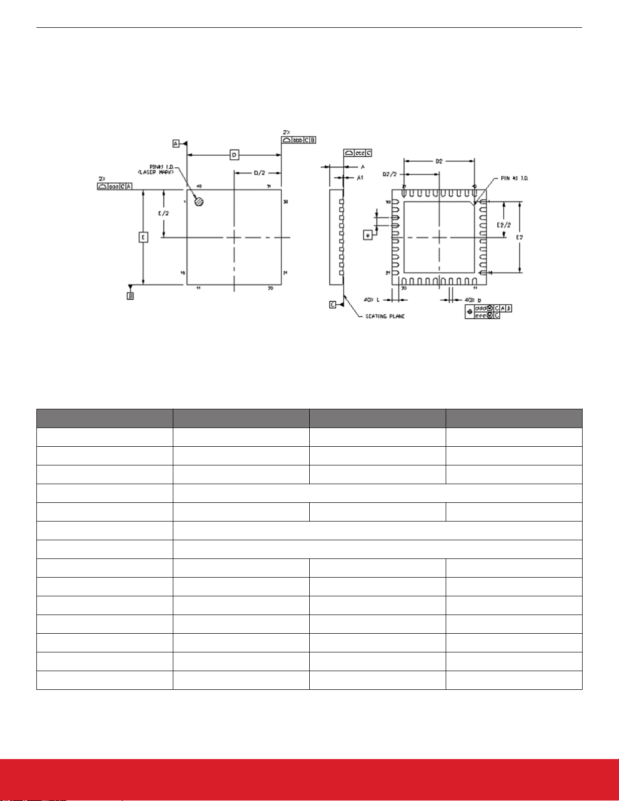
7.1 6x6 mm 40-QFN Package Diagram
The figure below illustrates the package details for 40-QFN. The table below lists the values for the dimensions shown in the illustration.
Figure 7.1. 40-Pin Quad Flat No-Lead (QFN)
Table 7.1. Package Dimensions
Dimension Min Nom Max
A 0.80 0.85 0.90
A1 0.00 0.02 0.05
b 0.18 0.25 0.30
D 6.00 BSC
D2 4.35 4.50 4.65
e 0.50 BSC
E 6.00 BSC
E2 4.35 4.50 4.65
L 0.30 0.40 0.50
aaa — — 0.15
bbb — — 0.15
ccc — — 0.08
ddd — — 0.10
eee 0.05
silabs.com | Building a more connected world. Rev. 1.0 | 29
Page 30

Dimension Min Nom Max
Notes:
1.
All dimensions shown are in millimeters (mm) unless otherwise noted.
Dimensioning and Tolerancing per ANSI Y14.5M-1994.
2.
3. This drawing conforms to the JEDEC Solid State Outline MO-220.
4. Recommended card reflow profile is per the JEDEC/IPC J-STD-020 specification for Small Body Components.
Si53258/Si53254 Data Sheet
Package Outline
silabs.com | Building a more connected world. Rev. 1.0 | 30
Page 31

7.2 5x5 mm 32-QFN Package Diagram
Si53258/Si53254 Data Sheet
Package Outline
The figure
illustration.
below illustrates the package details for 32-QFN option. The table below lists the values for the dimensions shown in the
Figure 7.2. 32-Pin Quad Flat No-Lead (QFN)
Table 7.2. Package Dimensions
Dimension MIN NOM MAX
A 0.80 0.85 0.90
A1 0.00 0.02 0.05
A3 0.20 REF
b 0.18 0.25 0.30
D/E 4.90 5.00 5.10
D2/E2 3.40 3.50 3.60
e 0.50 BSC
L 0.30 0.40 0.50
K 0.20 --- ---
R 0.09 --- 0.14
aaa 0.15
bbb 0.10
ccc 0.10
silabs.com | Building a more connected world. Rev. 1.0 | 31
Page 32
Dimension MIN NOM MAX
ddd 0.05
eee 0.08
fff 0.10
Notes:
1.
All dimensions shown are in millimeters (mm) unless otherwise noted.
Dimensioning and Tolerancing per ANSI Y14.5M-1994.
2.
3. This drawing conforms to the JEDEC Solid State Outline MO-220, Variation VKKD-4.
4. Recommended card reflow profile is per the JEDEC/IPC J-STD-020 specification for Small Body Components.
Si53258/Si53254 Data Sheet
Package Outline
silabs.com | Building a more connected world. Rev. 1.0 | 32
Page 33

8. PCB Land Pattern
8.1 40-QFN Land Pattern
Si53258/Si53254 Data Sheet
PCB Land Pattern
Figure 8.1. 40-QFN Land Pattern
Table 8.1. PCB Land Pattern Dimensions
Dimension mm
C1 5.90
C2 5.90
e 0.50 BSC
X1 0.30
Y1 0.85
X2 4.65
Y2 4.65
silabs.com | Building a more connected world. Rev. 1.0 | 33
Page 34
Si53258/Si53254 Data Sheet
PCB Land Pattern
Dimension mm
Notes:
General
1.
All dimensions shown are in millimeters (mm) unless otherwise noted.
This Land Pattern Design is based on the IPC-7351 guidelines.
2.
Solder Mask Design
1. All metal pads are to be non-solder mask defined (NSMD). Clearance between the solder mask and the metal pad is to be 60 µm
minimum, all the way around the pad.
Stencil Design
1. A stainless steel, laser-cut and electro-polished stencil with trapezoidal walls should be used to assure good solder paste release.
2. The stencil thickness should be 0.125 mm (5 mils).
3. The ratio of stencil aperture to land pad size can be 1:1 for all perimeter pads.
4. A 3×3 array of 0.85 mm square openings on a 1.00 mm pitch can be used for the center ground pad.
Card Assembly
1. A No-Clean, Type-3 solder paste is recommended.
2. The recommended card reflow profile is per the JEDEC/IPC J-STD-020 specification for Small Body Components.
silabs.com | Building a more connected world. Rev. 1.0 | 34
Page 35

8.2 32-QFN Land Pattern
Si53258/Si53254 Data Sheet
PCB Land Pattern
The figure
below illustrates the PCB land pattern details for 32-QFN package. The table below lists the values for the dimensions
shown in the illustration.
Figure 8.2. 32-QFN Land Pattern
Table 8.2. PCB Land Pattern Dimensions
Dimension mm
C1 4.90
C2 4.90
e 0.50 BSC
X1 0.30
Y1 0.85
X2 3.60
Y2 3.60
silabs.com | Building a more connected world. Rev. 1.0 | 35
Page 36

Si53258/Si53254 Data Sheet
PCB Land Pattern
Dimension mm
Notes:
General
1.
All dimensions shown are in millimeters (mm) unless otherwise noted.
This Land Pattern Design is based on the IPC-7351 guidelines.
2.
Solder Mask Design
1. All metal pads are to be non-solder mask defined (NSMD). Clearance between the solder mask and the metal pad is to be 60 µm
minimum, all the way around the pad.
Stencil Design
1. A stainless steel, laser-cut and electro-polished stencil with trapezoidal walls should be used to assure good solder paste release.
2. The stencil thickness should be 0.125 mm (5 mils).
3. The ratio of stencil aperture to land pad size can be 1:1 for all perimeter pads.
4. A 3×3 array of 0.85 mm square openings on a 1.00 mm pitch can be used for the center ground pad.
Card Assembly
1. A No-Clean, Type-3 solder paste is recommended.
2. The recommended card reflow profile is per the JEDEC/IPC J-STD-020 specification for Small Body Components.
silabs.com | Building a more connected world. Rev. 1.0 | 36
Page 37

9. Top Marking
Si53258/Si53254 Data Sheet
Top Marking
Standard Factory Default Configuration
S i 5 3 2 5 x
A R 0 x A
T T T T T T
Y Y WW
Figure 9.1. Top Marking
Table 9.1. Top Marking Explanation
Line Characters Description
1 Si53258
Si53254
2 A-D0xA
Base part number
A = Grade
R = Product revision (reference ordering section for latest revision)
0x = Product identification, single input:
•
01 = Single input
02 = Dual input
•
A = Automotive grade temperature range
3 TTTTTT Manufacturing trace code
4 YYWW Year (YY) and work week (WW) of package assembly
silabs.com | Building a more connected world. Rev. 1.0 | 37
Page 38

10. Revision History
Revision 1.0
January, 2021
•
Updated notes in Table 5.4 Differential Clock Output Specifications on page 10.
• Removed “default low” from OEb pin descriptions.
Revision 0.7
September, 2019
• Initial release.
Si53258/Si53254 Data Sheet
Revision History
silabs.com | Building a more connected world. Rev. 1.0 | 38
Page 39
ClockBuilder Pro
One-click access to Timing tools,
documentation, software, source
code libraries & more. Available for
Windows and iOS (CBGo only).
www.silabs.com/CBPro
Timing Portfolio
www.silabs.com/timing
Disclaimer
Silicon Labs intends to provide customers with the latest, accurate, and in-depth documentation of all peripherals and modules available for system and software implementers using or
intending to use the Silicon Labs products. Characterization data, available modules and peripherals, memory sizes and memory addresses refer to each specific device, and "Typical"
parameters provided can and do vary in different applications. Application examples described herein are for illustrative purposes only . Silicon Labs reserves the right to make changes without
further notice to the product information, specifications, and descriptions herein, and does not give warranties as to the accuracy or completeness of the included information. Without prior
notification, Silicon Labs may update product firmware during the manufacturing process for security or reliability reasons. Such changes will not alter the specifications or the performance
of the product. Silicon Labs shall have no liability for the consequences of use of the information supplied in this document. This document does not imply or expressly grant any license
to design or fabricate any integrated circuits. The products are not designed or authorized to be used within any FDA Class III devices, applications for which FDA premarket approval is
required, or Life Support Systems without the specific written consent of Silicon Labs. A "Life Support System" is any product or system intended to support or sustain life and/or health,
which, if it fails, can be reasonably expected to result in significant personal injury or death. Silicon Labs products are not designed or authorized for military applications. Silicon Labs
products shall under no circumstances be used in weapons of mass destruction including (but not limited to) nuclear, biological or chemical weapons, or missiles capable of delivering
such weapons. Silicon Labs disclaims all express and implied warranties and shall not be responsible or liable for any injuries or damages related to use of a Silicon Labs product in such
unauthorized applications.
Trademark Information
Silicon Laboratories Inc.®, Silicon Laboratories®, Silicon Labs®, SiLabs® and the Silicon Labs logo®, Bluegiga®, Bluegiga Logo®, ClockBuilder®, CMEMS®, DSPLL®, EFM®, EFM32®,
EFR, Ember®, Energy Micro, Energy Micro logo and combinations thereof, "the world’s most energy friendly microcontrollers", Ember®, EZLink®, EZRadio®, EZRadioPRO®, Gecko®,
Gecko OS, Gecko OS Studio, ISOmodem®, Precision32®, ProSLIC®, Simplicity Studio®, SiPHY®, Telegesis, the Telegesis Logo®, USBXpress® , Zentri, the Zentri logo and Zentri DMS, ZWave®, and others are trademarks or registered trademarks of Silicon Labs. ARM, CORTEX, Cortex-M3 and THUMB are trademarks or registered trademarks of ARM Holdings. Keil is a
registered trademark of ARM Limited. Wi-Fi is a registered trademark of the Wi-Fi Alliance. All other products or brand names mentioned herein are trademarks of their respective holders.
Silicon Laboratories Inc.
400 West Cesar Chavez
Austin, TX 78701
USA
SW/HW
www.silabs.com/CBPro
Quality
www.silabs.com/quality
Support and Community
community.silabs.com
http://www.silabs.com
 Loading...