

Page 1
AN1046: Radio Frequency Physical Layer
Evaluation in Bluetooth® SDK v2.x
This application note provides an overview of how to perform
Bluetooth-based radio frequency (RF) physical layer (PHY) evaluation with Bluetooth-enabled EFR32xG system-on-chips (SoCs)
and BGM/MGM modules using Silicon Labs’ software tools and
dedicated firmware. A Bluetooth device’s RF parameters are validated using a protocol called Direct Test Mode (DTM). DTM is
described in the Bluetooth Core Specification versions 4.x and
5.0, Volume 6, Part F.
Testing can be performed in three ways:
• Through DTM test commands issued by a host system over the SoC’s or module’s
host interface.
• Through DTM test commands issued by a custom application running in the SoC or
module itself. Such commands could be autonomously launched by the custom application, for example at boot or following the writing of a dedicated GATT characteristic by a remote companion device over a Bluetooth LE connection.
• In a special test environment supported by dedicated firmware that allows a testing
device to control the test target.
KEY POINTS
• Basics of Direct Test Mode (DTM)
• Testing with BGTool
• Testing with DTM 2-wire firmware
• Test examples
• Updates for Bluetooth 5.0
With these options, customers can fully evaluate transmit and receive performance,
and test the RF functionality of their development kit hardware or custom hardware.
Laboratory tests require RF test equipment, such as a spectrum analyzer and an RF
signal generator, and /or a Bluetooth tester.
silabs.com | Building a more connected world. Rev. 0.5
Page 2

AN1046: Radio Frequency Physical Layer Evaluation in Bluetooth® SDK v2.x
Basics of the Direct Test Mode (DTM)
1. Basics of the Direct Test Mode (DTM)
The Bluetooth specification defines a mechanism, called Direct Test Mode (DTM), for testing the radio performance of Bluetooth low
energy devices. This mechanism is described in the Bluetooth Core Specification, for example versions 4.2 and 5.0, Volume 6, Part F,
which are available at https://www.bluetooth.com/specifications/bluetooth-core-specification. DTM is provided for the validation of a
Bluetooth low energy device’s radio-frequency (RF) physical layer (PHY), so as to ultimately guarantee an end product’s interoperability
and performance quality. RF testing is essential for a Bluetooth device, as with any device implementing a wireless standardized technology, since factors such as full compliance with the specification for interoperability, and conformance to communication regulations
must be carefully assessed and validated before the product is launched. In addition, it may be desirable to evaluate the product’s performance during production. The ability to easily accomplish RF testing in a standardized manner throughout the production cycle is
useful.
DTM offers two approaches for RF PHY testing. In the first, an Upper Tester can enter special HCI (host control interface) commands
over the standardized HCI interface of the Device Under Test (DUT) to start and stop the radio tests on the DUT. In the second, the
Upper Tester has direct access to the DUT through a dedicated 2-wire connection, and can autonomously start and stop the radio tests
on the DUT in accordance with automated test routines.
The DTM protocol enabling the communication between the DUT and the Upper Tester also has provisions for feedback from the DUT,
in the form of acknowledgements to the commands given, or in the form of Packet Count information being reported at the time a test is
stopped.
A Lower Tester, or RF PHY Tester, is also part of the test setup, and is the actual lab equipment measuring the RF activity and performance. The RF PHY Tester can either be a separate device, like a spectrum analyzer, which is normally used with the first method
where the HCI commands are issued by a generic host system, or it can be part of the same device. In the latter case the RF PHY
Tester functions also as the Upper Tester, as for example commercial Bluetooth testers such as the one referenced later in this document.
The Bluetooth-enabled Silicon Labs EFR32xG SoCs and the BGM/MGM modules support both the approaches mentioned above. Special firmware can be loaded to enable the 2-wire DTM and allow the Upper Tester to take full control of the SoC or module (the device).
The 2-wire link is a UART-like connection with no flow control operating at baud rates between 1200-115200, 8N1 (8 data bits, no parity, 1 stop bit). As one alternative, any firmware that configures the device to operate in Network Co-Processor (NCP) mode can be
used, since the host system can then issue the test commands included with the BGAPI Bluetooth API over the same host interface
that is normally used to implement the BGAPI protocol for the control and configuration of the device’s normal Bluetooth LE functionality. Note that in this case BGAPI-formatted test commands are sent and not the HCI commands defined in the standard. However, these
BGAPI commands are then internally processed as HCI commands. The SDK does not contain any special firmware or configuration to
disable the BGAPI DTM commands/responses and use the raw HCI command/responses instead.
.
silabs.com | Building a more connected world. Rev. 0.5 | 2
Page 3

AN1046: Radio Frequency Physical Layer Evaluation in
Bluetooth® SDK v2.x
Tests Enabled in the DTM Framework
2. Tests Enabled in the DTM Framework
DTM enables a set of RF PHY test cases, which are defined by the Bluetooth Special Interest Group (SIG) in the documents from the
sections called “TCRL Release Table” and “Core - Test Requirements for v4.0 or later” found at the beginning of the https://www.blue-
tooth.com/specifications/qualification-test-requirements web page.
Note: The following information was updated in the first half of 2017. For current information, refer to the newer TCRL 2017-1, that is, to
the corresponding 2017-1 TCRLs-1.zip file containing the newer RF-PHY.TS.5.0.1.
The Capability tests (as defined in the standard ISO subgroups) are organized in levels and groups representing protocol services,
functional modules, and purposes, the latter being divided in operating conditions for the transmitter and the receiver. All the relevant
RF PHY tests are in accordance to the test specifications RF-PHY.TS.4.2.3 or the updated RF-PHY.TS.5.0.0 and are shown in the RFPHY sheet of the Excel file called Core.TCRL.2016-2.xlsx found inside the 2016-2 TCRLs.zip.
Below are examples of test cases for the Physical Layer Conformance. They are referred to by their identifiers, where TP stands for
Test Purpose and TRM-LE and RCV-LE stand for LE Transmitter and LE Receiver test respectively.
• TP/TRM-LE/CA/BV-01-C [Maximum peak and average output power]
• TP/TRM-LE/CA/BV-03-C [In-band spectral emissions]
• TP/TRM-LE/CA/BV-05-C [Modulation Characteristics]
• TP/TRM-LE/CA/BV-06-C [Carrier frequency offset and carrier drift]
• TP/RCV-LE/CA/BV-01-C [Receiver sensitivity]
• TP/RCV-LE/CA/BV-03-C [C/I and Receiver Selectivity Performance] [Additional blocker needed to generate co-/adjacent channel interference]
• TP/RCV-LE/CA/BV-04-C [Blocking Performance] [Additional blocker needed to generate interference outside the 2400MHz -
2483.5MHz band]
• TP/RCV-LE/CA/BV-05-C [Intermodulation Performance] [2 x additional blocker needed to generate both a sinusoidal/un-modulated
and a continuous/modulated carrier]
• TP/RCV-LE/CA/BV-06-C [Maximum input signal level]
• TP/RCV-LE/CA/BV-07-C [PER Report Integrity]
Additional test cases have been introduced since the release of Bluetooth 5. A few examples of the many new test cases are listed
below:
• TP/TRM-LE/CA/BV-08-C [In-band emissions at 2 Ms/s]
• TP/TRM-LE/CA/BV-10-C [Modulation Characteristics at 2 Ms/s]
• TP/RCV-LE/CA/BV-08-C [Receiver sensitivity at 2 Ms/s]
• TP/RCV-LE/CA/BV-10-C [Blocking performance at 2 Ms/s]
All the above tests can be performed with the EFR32xG SoCs and the BGM/MGM modules, because they are supported by the DTM
implementation built in to the Silicon Labs Bluetooth stack.
Notes:
1. According to the latest TCRLs, references to the Extreme Operating Conditions (EOC) and the Normal Operating Conditions
(NOC) have been removed, as they became redundant with the removal of the extreme operating test conditions.
2. To accomplish the full set of tests in the specification, up to two external signal generators are needed to provide complete interference signals, in addition to a spectrum analyzer.
silabs.com | Building a more connected world. Rev. 0.5 | 3
Page 4
AN1046: Radio Frequency Physical Layer Evaluation in
Bluetooth® SDK v2.x
Testing with BGTool
3. Testing with BGTool
An easy way to perform the RF PHY tests with the EFR32xG SoCs and the BGM/MGM modules is to use a PC running BGTool as the
Upper Tester. The SoC or module must be configured to operate in NCP mode.
AN1042: Using the Silicon Labs Bluetooth® Stack in Network Co-Processor Mode discusses the basics of the NCP firmware and how
to load it to a device, and provides an example to help familiarize you with the NCP mode. It also includes instructions on how to get
started controlling and configuring the Bluetooth functionality through the BGTool demo program. This chapter describes using BGTool
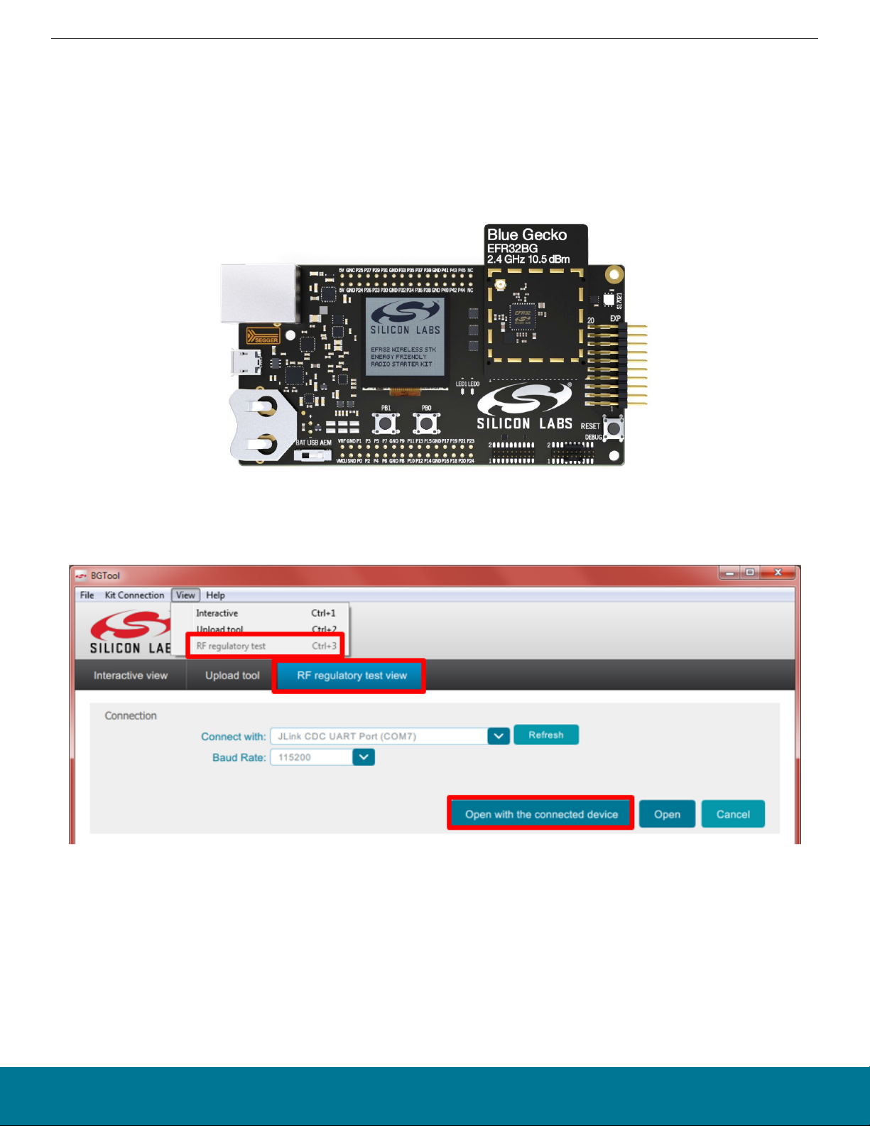
for RF PHY testing, where an SoC or module in a radio board attached to the Wireless Starter Kit (WSTK) is the example DUT, as
shown in the following figure.
Figure 3.1. WSTK with the Blue Gecko EFR32BG SoC
Launch BGTool and verify that the device in NCP mode responds to the commands entered in the Interactive view, Next, change to
the RF regulatory test view. Click Open with the connected device.
Figure 3.2. Entering the RF Regulatory Test View
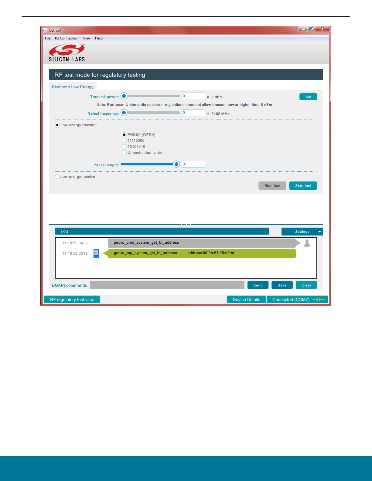
The control dialog shown in the following figure opens.
silabs.com | Building a more connected world. Rev. 0.5 | 4
Page 5
AN1046: Radio Frequency Physical Layer Evaluation in
Testing with BGTool
Bluetooth® SDK v2.x
Figure 3.3. RF Regulatory Test Control Dialog
In this dialog you can interact with the device and set the RF test parameters using the sliders and the radio buttons. All the necessary
configuration options are provided, namely transmission power level, operational frequency, packet type and length, and whether to
perform a transmit or receive test.
If you intend to perform transmit tests using anything other than the default transmit power, change the power and click Set next to the
Transmit power slider before launching your next test. Normally the default value is the maximum allowed by the firmware for a particular SoC or module. Clicking Set executes the BGAPI’s system_set_tx_power command, which changes the power value.
When the configuration parameters for the test are complete, click Start test. The test runs until you click Stop test.
silabs.com | Building a more connected world. Rev. 0.5 | 5
Page 6
AN1046: Radio Frequency Physical Layer Evaluation in
Bluetooth® SDK v2.x
Testing with BGTool
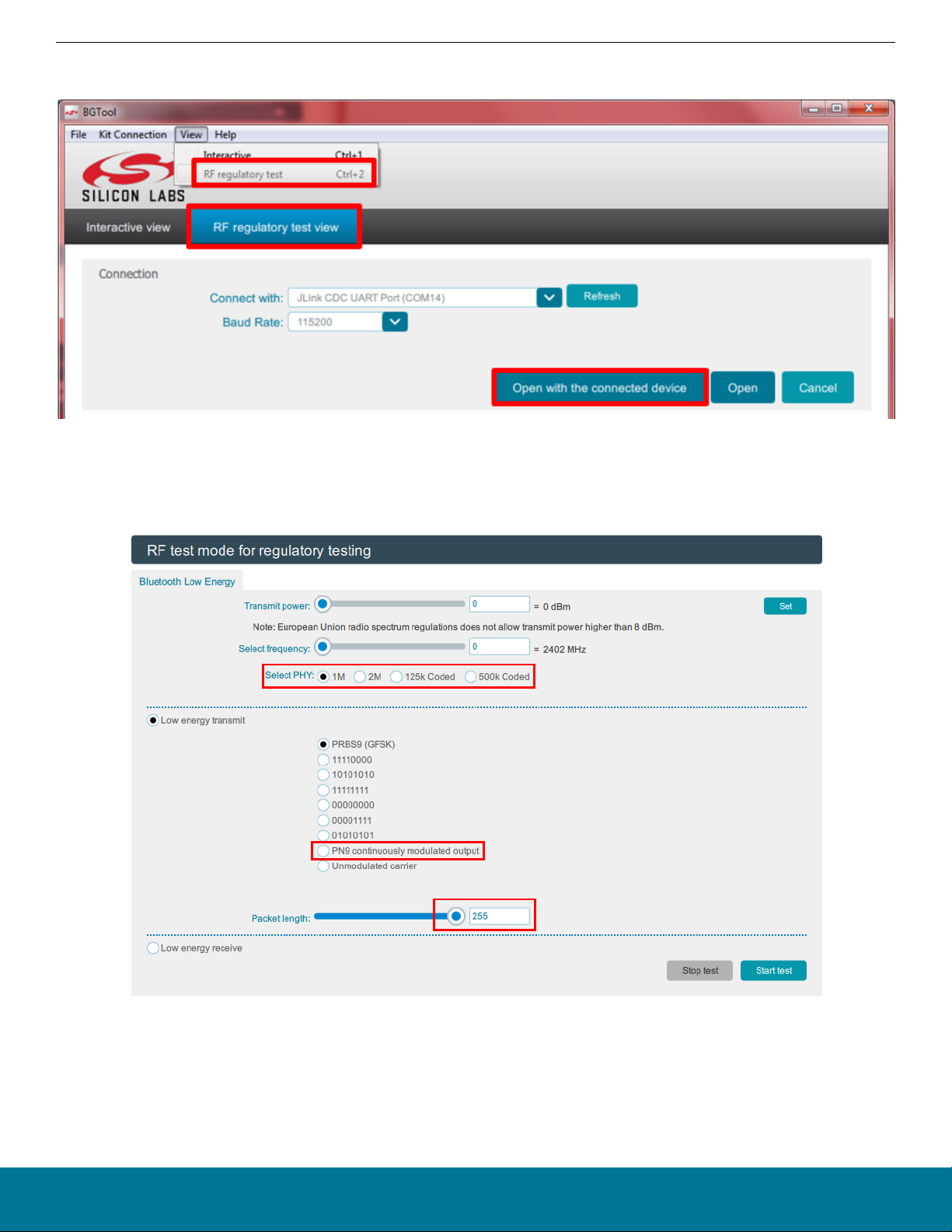
Depending on the SDK in use, the BGTool might present different views and contents, such as in the following where no firmware uploading section exists.
Figure 3.4. Entering the RF Regulatory Test View using the BGTool
The following figure shows the new PHY selection option with the most recent version of the BGTool for devices that support Bluetooth
5.0, together with the new option to select the PN9 continuously modulated carrier, and the possibility to extend the payload to up to
255 bytes.
Figure 3.5. Selecting the PHY with the BGTool
When you click the Start test button, BGTool sends one of the BGAPI’s DTM commands over the host interface of the device. The
command parameters correspond to the slider and radio button selections. The API’s DTM commands are summarized in the following
table.
silabs.com | Building a more connected world. Rev. 0.5 | 6
Page 7

Table 3.1. DTM Commands
Command Description
Starts a transmitter test. The DUT returns a response indicating that the command was received successfully. Shortly after this, a test_dtm_completed
event is triggered, indicating that the command was processed by the radio and
the actual test mode is started. At this point, the device is sending Bluetooth LE
packets continuously at a fixed interval defined in the specification. The test is
stopped using the test_dtm_end command, which is also followed by a
test_dtm_completed event.
Only when a test_dtm_completed event follows the test_dtm_end command,
and only with firmware versions 2.4.0 and above, the event's
number_of_packets field carries the actual number of packets sent during the
test_dtm_tx(packet_type, length, channel)
or
test_dtm_tx(packet_type, length, channel,
phy)
test.
The type and length of each packet is set by the packet_type and length parameters. The newest firmware versions add a parameter called phy that allows
the selection of the PHY among 1M, 2M, 125k Coded, and 500k Coded, when
supported by the DUT.
Note that a special packet type named test_pkt_carrier exists (enumerating
to a value of 3, or 254 beginning with version 2.4.1.0, for the parameter
packet_type) that can be used to transmit a continuous unmodulated carrier.
The length field is ignored in this mode. Version 2.4.1.0 also introduces yet another special packet type named test_pkt_pn9 (enumerating to a value of 253)
that can be used to transmit a continuous modulated carrier instead, by mean of
a PN9 stream offering a 100% duty cycle.
AN1046: Radio Frequency Physical Layer Evaluation in
Testing with BGTool
Bluetooth® SDK v2.x
In general, for the regulatory testing PRBS9 (packet_type of 0) and/or the continuous modulated carrier are used, whereas the other two packet payloads (packet_type of 1 or 2) are used when testing for the Bluetooth qualification.
test_dtm_rx(channel)
Starts a receiver test. The procedure is similar to the transmitter test described
above. When ending the test with the test_dtm_end command, the expected
or
test_dtm_rx(channel, phy)
test_dtm_completed event from the device carries in its number_of_packets
field the actual number of packets received during the test.
Can be issued at any time to end a transmitter or a receiver test. When the com-
test_dtm_end()
mand is processed by the radio and the test has ended, a test_dtm_completed
event is triggered.
The commands with their related responses, and the event mentioned in the table above, are found in the Bluetooth Software API Ref-
erence.
Note: Once a test is started the normal Bluetooth LE functionality is not available, in other words, advertising and scanning are not
possible while a test is running, and similarly no connection can exist.
silabs.com | Building a more connected world. Rev. 0.5 | 7
Page 8
AN1046: Radio Frequency Physical Layer Evaluation in
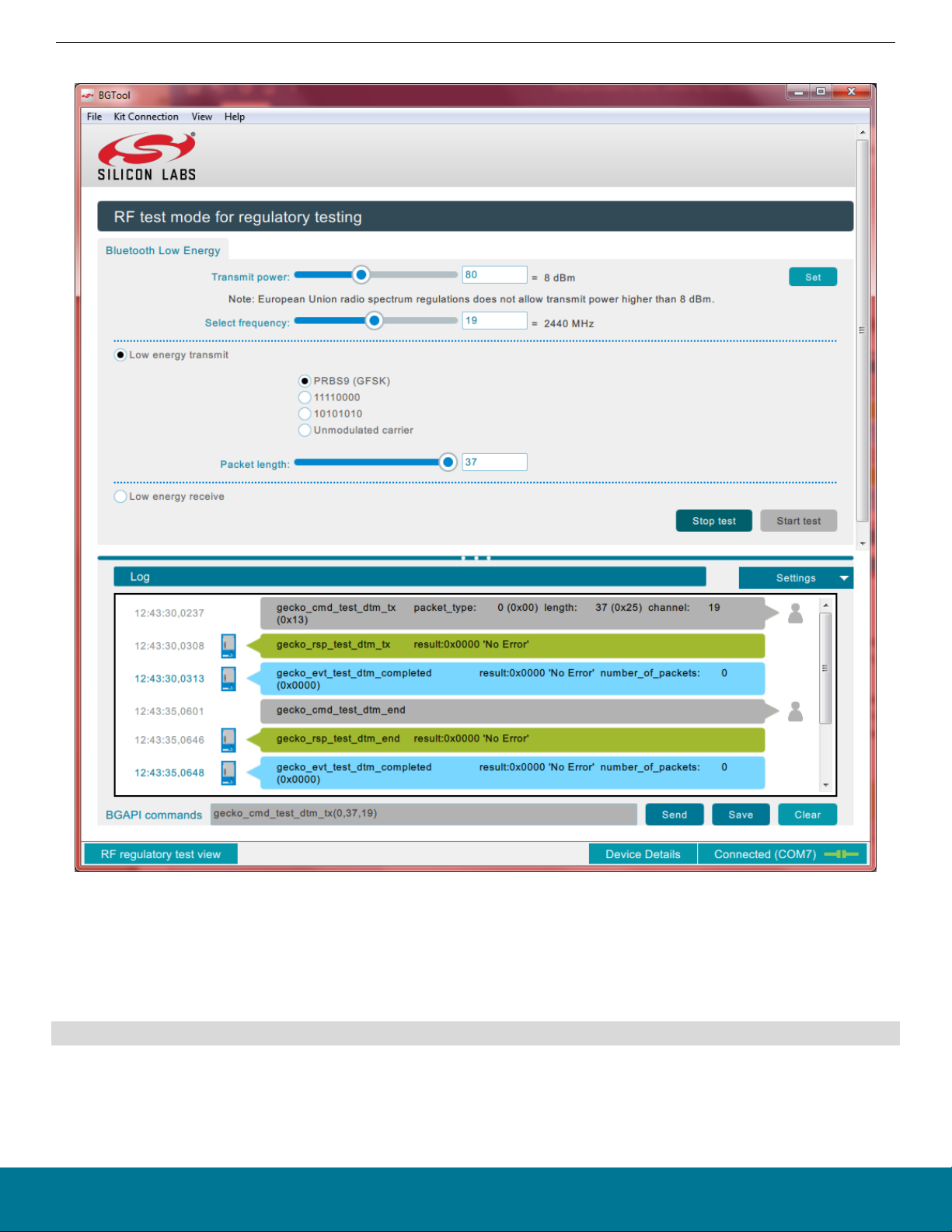
The following figure shows an example of the commands and responses and events in an actual test.
Bluetooth® SDK v2.x
Testing with BGTool
Figure 3.6. Starting and Stopping a Transmission Test
In this example, the test is started by clicking Start test. After a DTM test is started, the device will only accept the test_dtm_end command, which is entered by clicking Stop test. The only other ways to stop a test are by resetting the device or through a power-cycle.
Another way to start and stop tests with BGTool is by entering the commands with the desired parameters in the command field at the
bottom of the BGTool window, labeled BGAPI commands. Such commands can be copy-pasted from the API reference, for example:
gecko_cmd_test_dtm_tx(0,37,19)
Using BGTool is just one of the ways to perform the RF PHY tests in the lab. In fact, the DTM commands from the BGAPI protocol are
also available to any host MCU capable of issuing the BGAPI commands over the device’s host interface, for example when implementing a host program based on the BGLib library.
silabs.com | Building a more connected world. Rev. 0.5 | 8
Page 9

AN1046: Radio Frequency Physical Layer Evaluation in
Bluetooth® SDK v2.x
Testing with BGTool
The commands can also be launched by a DUT operating in standalone mode, by means of a custom C program loaded onto the SoC/
module. Users could start with the SOC-Empty example project, and customize it to simply have a test command autonomously
launched at boot and terminated by a hard reset or after a timer has expired. Alternatively, the program could be designed to allow an
incoming Bluetooth LE connection over which a remote device could write a dedicated GATT characteristic. The characteristic's content
would define the test command the application should launch and how long this should run until a terminating event such as allowing
the next connection or a reset.
Using this programming strategy, customers often prepare multiple firmware images for their test house, each containing the standalone functionality to launch a specific test at bootup, and then simply provide instructions to the test house on how to change firmware
images.
Notes and Limitations:
1. The DTM tests discussed in this section are meant for regulatory testing as well as for Bluetooth qualification. All tests are designed to satisfy the guidelines normally set by the test houses that will conduct the regulatory evaluation.
2. During a 1M PHY transmit test where the typical 37 bytes of payload are used, subsequent packet transmissions are started at an
interval of 625 µs. In this case, the packet transmission itself lasts 376 µs, resulting in a duty cycle of 60.2%. This comes from the
fact that the packet used in the test is made of a preamble (8 bit) plus a sync word (32 bit) plus a packet type field (16 bit) plus the
payload (296 bit) plus the CRC (24 bit), while the time to transmit one bit is 1 µs given the air-interface baud rate of 1 Mbit/s. The
max payload size that can be configured with the test_dtm_tx command is 37 bytes with older firmware versions, but can be up to
128 bytes since firmware version 2.3.0.0, and up to 255 bytes since version 2.6.0.0, according to the LE Data Packet Length Extension introduced in the Core Specification version 4.2. Given all the new possible combinations of PHYs and packet lengths in
the newest firmware versions, the duty cycle will actually depend now also on the interval between packets which is not fixed but
calculated based on the information found in the Core Specification version 4.2 and 5, in chapter “4.1.6 LE Test Packet Interval” of
Volume 6, Part F.
3. In firmware versions 2.3.x.x and earlier, no configuration option exists to output a continuously modulated RF signal. Some of the
FCC test procedures might require a modulated output at >= 98% duty cycle. Testing with such a duty cycle is not needed when an
AVG detector (recommended) is available. But when an AVG detector is not part of the lab testing equipment, and since it is not
possible to output the continuously modulated RF signal, then testing might involve measuring the duty cycle in the time domain
and then applying a positive correction factor, as discussed in the FCC presentation at:
https://transition.fcc.gov/bureaus/oet/ea/presentations/files/apr12/2a.-April-12-DTS-Presentation-SJ.pdf
Starting with firmware version 2.4.0.0, a new packet type is defined for the test_dtm_tx command to let the DUT generate a continuously modulated RF signal in addition to the continuous unmodulated carrier. For more information, see Table 3.1 DTM Com-
mands on page 7.
4. As of this document version, no configuration option exists to define a fixed amount of packets that the device would transmit after
issuing the test_dtm_tx command. One useful use case would be to estimate packets lost: the test setup would have a transmitter sending a number of packets known in advance and a receiver reporting the number of packets received (via the
test_dtm_completed event). This could evaluate performance changes due to distance or other conditions, or be used during pro-
duction to validate the quality of a product just manufactured. The workaround for the lack of such a configuration option is to let
the unit transmit only for a fixed amount of time, calculated by taking into account the interval at which the packets are transmitted:
in the example case of a 1M PHY and 37 bytes payload, having the interval between packets set to 625 µs, the packet rate is 1600
[packets/s].
Note: Starting with firmware versions 2.4.0 and above, the test_dtm_completed event reports the actual packets sent during the
test when the test mode launched with the test_dtm_tx command is stopped. This is useful for a precise estimation of the PER
when comparing the exact number of packets sent by the stack with the actual packets received by the receiver.
silabs.com | Building a more connected world. Rev. 0.5 | 9
Page 10

AN1046: Radio Frequency Physical Layer Evaluation in Bluetooth® SDK v2.x
Testing with the DTM 2-Wire Firmware
4. Testing with the DTM 2-Wire Firmware
If a Bluetooth tester device is available, it should be used to evaluate the RF performance of the DUT, since such dedicated equipment
is faster and offers automated and accurate testing. These benefits among others are achieved because the tester can control and
configure the DUT in all the tests required for complete RF PHY evaluation. Such control is possible thanks to the DTM 2-wire capability
and its related protocol, which are part of the Bluetooth specification.
In order to enable the DTM 2-wire communication between a commercial Bluetooth tester device (that is, the Upper Tester with the
included RF PHY measurement capability) and the DUT, the latter needs to run a special firmware where the protocol is included. This
special DTM 2-wire-capable firmware was first released with Silicon Labs Bluetooth SDK version 2.1.0.0, and is available through the
Simplicity Studio v4, as shown in the following figure.
Figure 4.1. DTM 2-Wire Firmware from Simplicity Studio v4 Launcher Perspective
silabs.com | Building a more connected world. Rev. 0.5 | 10
Page 11

AN1046: Radio Frequency Physical Layer Evaluation in Bluetooth® SDK v2.x
Testing with the DTM 2-Wire Firmware
4.1 Using the Precompiled Demo Version
The demo version of the DTM firmware is a ready-to-use solution if the following test configuration is acceptable:
• The hardware link to the Bluetooth tester is enabled over the device’s pins that, in its evaluation radio board, are mapped to the
WSTK expansion header’s UART TX (pin 12) and UART RX (pin 14).
• The link uses UART parameters of 115200, 8N1 with no hardware flow control.
Refer to the documentation of a particular SoC or module and of its evaluation radio board to determine which pins are in use in order
to have the DTM signaling routed to the intended expansion header pins.
To program a device with the DTM demo, under the Demos column in the Simplicity Studio launcher click the SOC - DTM demo. In the
next dialog, confirm the demo and mode, and click Start. The demo is then loaded onto the device.
Figure 4.2. Confirming the DTM 2-wire Firmware Demo
silabs.com | Building a more connected world. Rev. 0.5 | 11
Page 12

AN1046: Radio Frequency Physical Layer Evaluation in Bluetooth® SDK v2.x
Figure 4.3. Upload in Progress
Testing with the DTM 2-Wire Firmware
silabs.com | Building a more connected world. Rev. 0.5 | 12
Page 13

AN1046: Radio Frequency Physical Layer Evaluation in
Bluetooth® SDK v2.x
Testing with the DTM 2-Wire Firmware
4.2 Connecting and Testing with the Bluetooth tester
With the demo firmware installed, the DUT is ready to be wired to the Bluetooth tester, as shown in the following figure. Testing can be
carried on at the Upper Tester interface, normally through PC software, as shown in the example using Anritsu MT8852B as the Bluetooth tester (Figure 4.5 Connecting the Upper Tester to the DUT on page 13 to Figure 4.7 Receiver Measurements (PER) on page
15).
Figure 4.4. Connecting the Bluetooth Tester to the WSTK
First, establish the connection to the DUT with the correct parameters, as highlighted in the following figure.
Figure 4.5. Connecting the Upper Tester to the DUT
Next, pre-existing or custom scripts can be used to start a suite of tests, as shown in the following figure. In the same figure the test
report is displayed by the tester PC program, after the automated tests have completed, with an overall result of “Passed”. Notice also
silabs.com | Building a more connected world. Rev. 0.5 | 13
Page 14

AN1046: Radio Frequency Physical Layer Evaluation in
Bluetooth® SDK v2.x
Testing with the DTM 2-Wire Firmware
the Fixed Offset field in the Script Setup box, which can be used to compensate for power loss, for example over the coaxial antenna
cable in the case of conducted RF tests.
Figure 4.6. Launching a Suite of Tests / Test Results
silabs.com | Building a more connected world. Rev. 0.5 | 14
Page 15

AN1046: Radio Frequency Physical Layer Evaluation in
Bluetooth® SDK v2.x
Testing with the DTM 2-Wire Firmware
Any commercial Bluetooth tester should be capable of testing among others the Packet Error Rate (PER). In this test configuration, the
Upper Tester first configures the DUT into receiving mode using the appropriate DTM 2-wire command (step 2 in the figure below after
the test configuration by the user in step 1), and then the Upper Tester starts sending a defined number of packets at the RF TX power
level configured by the user (step 3). When the test is ended by the user (step 4), the corresponding DTM 2-wire command is also sent
to the DUT and, much as in the BGAPI test_dtm_completed event discussed earlier, the DUT reports over the 2-wire link the number
of received packets so that the Upper Tester can calculate the PER, all according to the specification.
Figure 4.7. Receiver Measurements (PER)
silabs.com | Building a more connected world. Rev. 0.5 | 15
Page 16

AN1046: Radio Frequency Physical Layer Evaluation in Bluetooth® SDK v2.x
Testing with the DTM 2-Wire Firmware
4.3 Testing Equipment Considerations
Certain Bluetooth testers, like the Anritsu MT8852B mentioned in this application note, use RS232 interfaces to connect to a DUT for
the DTM 2-wire, meaning that, when testing with the demo firmware and a WSTK, for example, a level shifter is needed in order to
interface to the device’s TTL logic.
Certain Bluetooth testers have no capability to generate RF signals with a power lower than a certain value, for example -90 dBm in the
case of the Anritsu MT8852B mentioned in this application note. Given that modern SoCs/modules have a receiver sensitivity going
well below that, an attenuator might be required for appropriate testing, to further decrease the power of a signal directed to the device
in receiving test mode.
silabs.com | Building a more connected world. Rev. 0.5 | 16
Page 17

AN1046: Radio Frequency Physical Layer Evaluation in Bluetooth® SDK v2.x
Testing with the DTM 2-Wire Firmware
4.4 Customizing the SOC - DTM Application
To configure the device to use other pins and other settings for the 2-wire UART, instead of selecting the precompiled application under
Demos in Simplicity Studio’s Launcher perspective, select the source SOC - DTM under the Software Examples column. The Simplicity
IDE perspective opens and a new project is started, allowing the creation of custom firmware implementing the desired hardware configuration.
Beginning with firmware/SDK version 2.6.0.0 the Hardware Configurator is removed and any hardware re-configuration should be made
in accordance to the guidelines in the “Example Project Walkthrough” chapter from AN1042: Using the Silicon Labs Bluetooth® Stack in
Network Co-Processor Mode.
If you are working in earlier SDK versions (before 2.6.0.0), at this point the Hardware Configurator shown in the following figure can be
used to re-configure the UART pin mapping, while parameters such as the baud rate, for example, can be re-configured by editing the
InitDevice.c source file as shown in Figure 4.9 Editing the InitDevice.c in the Simplicity IDE on page 18, or through the Hardware
Configurator’s other view, shown in Figure 4.10 Hardware Configurator in Simplicity Studio v4 / UART Properties on page 19.
Figure 4.8. Hardware Configurator in Simplicity Studio v4 / UART Pin Mapping
silabs.com | Building a more connected world. Rev. 0.5 | 17
Page 18

AN1046: Radio Frequency Physical Layer Evaluation in Bluetooth® SDK v2.x
Testing with the DTM 2-Wire Firmware
Figure 4.9. Editing the InitDevice.c in the Simplicity IDE
silabs.com | Building a more connected world. Rev. 0.5 | 18
Page 19

AN1046: Radio Frequency Physical Layer Evaluation in Bluetooth® SDK v2.x
Testing with the DTM 2-Wire Firmware
Figure 4.10. Hardware Configurator in Simplicity Studio v4 / UART Properties
silabs.com | Building a more connected world. Rev. 0.5 | 19
Page 20

AN1046: Radio Frequency Physical Layer Evaluation in Bluetooth® SDK v2.x
Testing with the DTM 2-Wire Firmware
In the Simplicity Studio screenshot shown in Figure 4.1 DTM 2-Wire Firmware from Simplicity Studio v4 Launcher Perspective on page
10, a WSTK with a radio board carrying an EFR32BG was attached to the PC. More often a custom design is used instead, and this is
obviously not recognized by the Silicon Labs’ software. In this case, no demos or software examples will appear in the Simplicity Studio’s Launcher perspective. However, the SOC – DTM software example can be used for this case as well, and it can be made available as seen in the following figures.
1. Under My Products, select a product. Start entering a product name to see a matching list of items.
2. Click [New Project].
3. Select the Bluetooth SDK.
Figure 4.11. Adding the SoC or the Module in a Custom Design
Figure 4.12. Selecting the New Project's Framework or SDK
silabs.com | Building a more connected world. Rev. 0.5 | 20
Page 21

4. Select the SOC - DTM example.
AN1046: Radio Frequency Physical Layer Evaluation in Bluetooth® SDK v2.x
Testing with the DTM 2-Wire Firmware
Figure 4.13. Selecting the SOC – DTM Application for a Custom Design
5. You are now in the IDE perspective, with a view similar to the one shown in Figure 4.9 Editing the InitDevice.c in the Simplicity IDE
on page 18.
silabs.com | Building a more connected world. Rev. 0.5 | 21
Page 22

AN1046: Radio Frequency Physical Layer Evaluation in Bluetooth® SDK v2.x
Test Examples with the BGAPI Commands test_dtm_tx and test_dtm_rx
5. Test Examples with the BGAPI Commands test_dtm_tx and test_dtm_rx
5.1 Output Power—TP/TRM-LE/CA/BV-01-C
The power basic measurement is used to make all of the output power measurements.
In this example, the test_dtm_tx command is used.
In this test mode, only the frequency and the output power are configurable parameters.
A spectrum analyzer is used to measure the power of the radio and must be connected through a compatible RF cable to the RF connector of the radio board.
It is also possible to test the output power with a separate Bluetooth tester device when the DTM firmware is installed in the DUT.
Figure 5.1. Output Power Measurement with the Rohde & Schwarz CBT Bluetooth Tester
silabs.com | Building a more connected world. Rev. 0.5 | 22
Page 23

AN1046: Radio Frequency Physical Layer Evaluation in Bluetooth® SDK v2.x
Test Examples with the BGAPI Commands test_dtm_tx and test_dtm_rx
5.2 Modulation—TP/TRM-LE/CA/BV-05-C and TP/TRM-LE/CA/BV-06-C
Used to make the modulation, and frequency offset and drift measurements.
In this example, the test_dtm_tx command is used.
To follow the test specification, you need to be able to change your payload data pattern (either 1010 pattern or 11110000 pattern).
A spectrum analyzer is used to measure the modulation, frequency offset, and drift measurements of the radio and must be connected
through a compatible RF cable to the RF connector of the radio board.
It is also possible to test by using a separate Bluetooth tester device provided that the DTM firmware is installed in the DUT.
Figure 5.2. Modulation Characteristics
silabs.com | Building a more connected world. Rev. 0.5 | 23
Page 24

AN1046: Radio Frequency Physical Layer Evaluation in Bluetooth® SDK v2.x
Test Examples with the BGAPI Commands test_dtm_tx and test_dtm_rx
5.3 Spectrum—TP/TRM-LE/CA/BV-03-C
Used for in-band emissions measurements.
In this example, the test_dtm_tx command is used.
A spectrum analyzer is used to measure the spectrum of the radio and must be connected through a compatible RF cable to the RF
connector of the radio board.
It is also possible to use a separate Bluetooth tester device provided that the DTM firmware is installed in the DUT.
Figure 5.3. Spectrum Test
silabs.com | Building a more connected world. Rev. 0.5 | 24
Page 25

AN1046: Radio Frequency Physical Layer Evaluation in Bluetooth® SDK v2.x
Test Examples with the BGAPI Commands test_dtm_tx and test_dtm_rx
5.4 Receiver Tests
Used to make all of the sensitivity-based measurements, as well as blocker measurements.
In this example, the test_dtm_rx command is used. In BGTool the test is started by selecting Low energy receive and then pressing
the Start test button.
A spectrum analyzer and two RF generators are used to validate the receiver tests and must be connected through a compatible RF
cable to the RF connector of the radio board.
A separate Bluetooth tester device can be used, but you might have to consider adding to it an external signal generator to provide the
second interferer or blocker signal.
Figure 5.4. Receiver Test
silabs.com | Building a more connected world. Rev. 0.5 | 25
Page 26

Simplicity Studio
One-click access to MCU and
wireless tools, documentation,
software, source code libraries &
more. Available for Windows,
Mac and Linux!
IoT Portfolio
www.silabs.com/IoT
Disclaimer
Silicon Labs intends to provide customers with the latest, accurate, and in-depth documentation of all peripherals and modules available for system and software implementers using or
intending to use the Silicon Labs products. Characterization data, available modules and peripherals, memory sizes and memory addresses refer to each specific device, and "Typical"
parameters provided can and do vary in different applications. Application examples described herein are for illustrative purposes only . Silicon Labs reserves the right to make changes without
further notice to the product information, specifications, and descriptions herein, and does not give warranties as to the accuracy or completeness of the included information. Without prior
notification, Silicon Labs may update product firmware during the manufacturing process for security or reliability reasons. Such changes will not alter the specifications or the performance
of the product. Silicon Labs shall have no liability for the consequences of use of the information supplied in this document. This document does not imply or expressly grant any license
to design or fabricate any integrated circuits. The products are not designed or authorized to be used within any FDA Class III devices, applications for which FDA premarket approval is
required, or Life Support Systems without the specific written consent of Silicon Labs. A "Life Support System" is any product or system intended to support or sustain life and/or health,
which, if it fails, can be reasonably expected to result in significant personal injury or death. Silicon Labs products are not designed or authorized for military applications. Silicon Labs
products shall under no circumstances be used in weapons of mass destruction including (but not limited to) nuclear, biological or chemical weapons, or missiles capable of delivering
such weapons. Silicon Labs disclaims all express and implied warranties and shall not be responsible or liable for any injuries or damages related to use of a Silicon Labs product in such
unauthorized applications.
Trademark Information
Silicon Laboratories Inc.®, Silicon Laboratories®, Silicon Labs®, SiLabs® and the Silicon Labs logo®, Bluegiga®, Bluegiga Logo®, ClockBuilder®, CMEMS®, DSPLL®, EFM®, EFM32®,
EFR, Ember®, Energy Micro, Energy Micro logo and combinations thereof, "the world’s most energy friendly microcontrollers", Ember®, EZLink®, EZRadio®, EZRadioPRO®, Gecko®,
Gecko OS, Gecko OS Studio, ISOmodem®, Precision32®, ProSLIC®, Simplicity Studio®, SiPHY®, Telegesis, the Telegesis Logo®, USBXpress® , Zentri, the Zentri logo and Zentri DMS, ZWave®, and others are trademarks or registered trademarks of Silicon Labs. ARM, CORTEX, Cortex-M3 and THUMB are trademarks or registered trademarks of ARM Holdings. Keil is a
registered trademark of ARM Limited. Wi-Fi is a registered trademark of the Wi-Fi Alliance. All other products or brand names mentioned herein are trademarks of their respective holders.
Silicon Laboratories Inc.
400 West Cesar Chavez
Austin, TX 78701
USA
SW/HW
www.silabs.com/simplicity
Quality
www.silabs.com/quality
Support and Community
community.silabs.com
http://www.silabs.com
 Loading...