

Page 1

AN1017: Zigbee® and OpenThread
Coexistence with Wi-Fi®
This application note describes methods to improve coexistence of
2.4 GHz IEEE 802.11b/g/n Wi-Fi and IEEE 802.15.4-based radios
such as Zigbee® and OpenThread. This application note assumes
you have a basic understanding of the concepts and principles of
Wi-Fi coexistence with 802.15.4 radios and how Wi-Fi coexistence
is implemented on EFR32 devices. For more information, see
UG103.17: Wi-Fi® Coexistence Fundamentals.
This application note describes EFR32 Zigbee and OpenThread coexistence support for
EmberZNet PRO 6.9.0.0 and OpenThread 1.1.0.0. See 5 Document Revision History for
a summary of key changes in previous revisions of this application note.
For additional details about the implementation of managed coexistence are included in
AN1243: Timing and Test Data for EFR32 Coexistence with Wi-Fi, available under nondisclosure from Silicon Labs Sales.
KEY POINTS
• Configure Wi-Fi coexistence for Zigbee
(AppBuilder) and OpenThread (the Component Editor).
• Use coexistence CLI commands for
Zigbee and OpenThread.
• Order the Coexistence Backplane Evalu-
ation Board.
silabs.com | Building a more connected world. Rev. 2.3
Page 2

AN1017: Zigbee® and Silicon Labs® Thread Coexistence with Wi-Fi®
Contents
Contents
1. Introduction ............................................................................................................................................... 3
2. Configuring Wi-Fi Coexistence ............................................................................................................... 4
2.1. PTA Software Setup with AppBuilder (Zigbee) ................................................................................. 4
2.2. PTA Software Setup with the Component Editor (OpenThread) ....................................................... 6
2.3. Coexistence Configurations .............................................................................................................. 9
2.3.1. REQUEST ............................................................................................................................ 9
2.3.1.1. Receive Retry ...................................................................................................... 9
2.3.2. GRANT ............................................................................................................................... 10
2.3.2.1. Abort Transmission Mid Packet If GRANT Is Lost ............................................. 10
2.3.2.2. ACK Disable ...................................................................................................... 11
2.3.3. PRIORITY........................................................................................................................... 11
2.3.4. PWM................................................................................................................................... 13
2.3.5. Radio Hold Off .................................................................................................................... 14
2.3.6. Directional PRIORITY ......................................................................................................... 14
2.3.7. Radio Blocker Optimization ................................................................................................. 17
2.3.7.1. Enable Runtime Control (Zigbee) /
SL_RAIL_UTIL_COEX_RUNTIME_PHY_SELECT (OpenThread) ................................ 17
2.3.7.2. Optional “Wi-Fi Select” Control of Blocker Optimization (Zigbee) /
SL_RAIL_UTIL_COEX_PHY_SELECT (OpenThread) .................................................. 17
2.3.8. RX Active ............................................................................................................................ 18
2.4. Run-Time PTA Re-configuration..................................................................................................... 19
2.4.1. PTA Option Descriptions..................................................................................................... 19
2.4.2. Application API (Zigbee) ..................................................................................................... 20
2.4.2.1. SoC Application API (Zigbee) ............................................................................ 20
2.4.2.2. Zigbee Network Coprocessor Application using EZSP API ................................ 21
2.4.3. Application API (OpenThread) ............................................................................................ 22
2.4.3.1. SoC Application API (OpenThread) ................................................................... 22
2.5. Coexistence Configuration Setup Examples for Different Wi-Fi/PTA Applications (Zigbee) ............ 24
3. Coexistence CLI Commands ................................................................................................................ 29
3.1. Coexistence CLI Commands (Zigbee) ............................................................................................ 29
3.1.1. PTA-specific Debug Counters ............................................................................................. 29
3.2. Coexistence CLI Commands (OpenThread) ................................................................................... 30
silabs.com | Building a more connected world. Rev. 2.3 | 1
Page 3

AN1017: Zigbee® and Silicon Labs® Thread Coexistence with Wi-Fi®
Contents
3.2.1. PTA-specific Debug Counters ............................................................................................. 31
4. Coexistence Backplane Evaluation Board (EVB) ............................................................................... 32
5. Document Revision History .................................................................................................................. 33
silabs.com | Building a more connected world. Rev. 2.3 | 2
Page 4

AN1017: Zigbee® and Silicon Labs® Thread Coexistence with Wi-Fi®
Introduction
1. Introduction
This application note includes the following sections:
• 2 Configuring Wi-Fi Coexistence describes how to configure the Silicon Labs Packet Traffic Arbitration (PTA) using AppBuilder for
Zigbee and the Simplicity Studio
®
(SSv5) Component Editor for OpenThread.
• 3 Coexistence CLI Commands describes how to use Command Line Interface (CLI) commands for Zigbee and OpenThread.
• 4 Coexistence Backplane Evaluation Board (EVB) explains how to order the EVB for evaluating the Silicon Labs EFR32 software
coexistence solution and introduces the Silicon Labs Wi-Fi Coexistence Learning Center.
silabs.com | Building a more connected world. Rev. 2.3 | 3
Page 5
AN1017: Zigbee® and Silicon Labs® Thread Coexistence with Wi-Fi®
Configuring Wi-Fi Coexistence
2. Configuring Wi-Fi Coexistence
2.1. PTA Software Setup with AppBuilder (Zigbee)
GPIO interrupt numbers are based on the GPIO pin numbers and not the port. This can cause conflicts if the same pin is selected for
different ports—for example, SPI_CS on PB01 will conflict with GRANT on PC01 because they will both have 1 as an interrupt number.
Silicon Labs recommends avoiding these conflicts. If the conflict exists in hardware, you can add the following coexistence macros in the
Additional Macros section of the Simplicity IDE tab:
• BSP_COEX_GNT_INTNO
• BSP_COEX_PRI_INTNO
• BSP_COEX_PWM_REQ_INTNO
• BSP_COEX_REQ_INTNO
• BSP_COEX_RHO_INTNO
Use the Configurator DefaultMode PORTIO map as a guide to determine which interrupt number to use in the Additional Macros Value
column by avoiding port pin numbers in use by other GPIO interrupts.
The steps to set up PTA Software for Zigbee using AppBuilder are described below. These steps assume you have installed Simplicity
Studio 5 and the EmberZNet SDK (Software Development Kit) and that you have a project open in the Simplicity IDE (Integrated Development Environment).
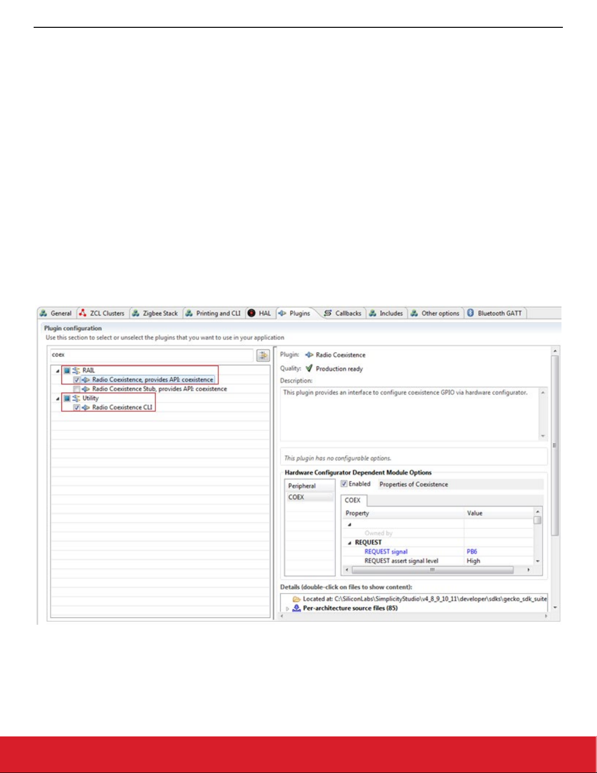
1. Select the Radio Coexistence plugin under the RAIL section of the Plugins tab. Under the Utility section selecting the Radio Coex-
istence CLI plugin is optional but recommended.
Figure 2-1. Install Radio Coexistence Plugin
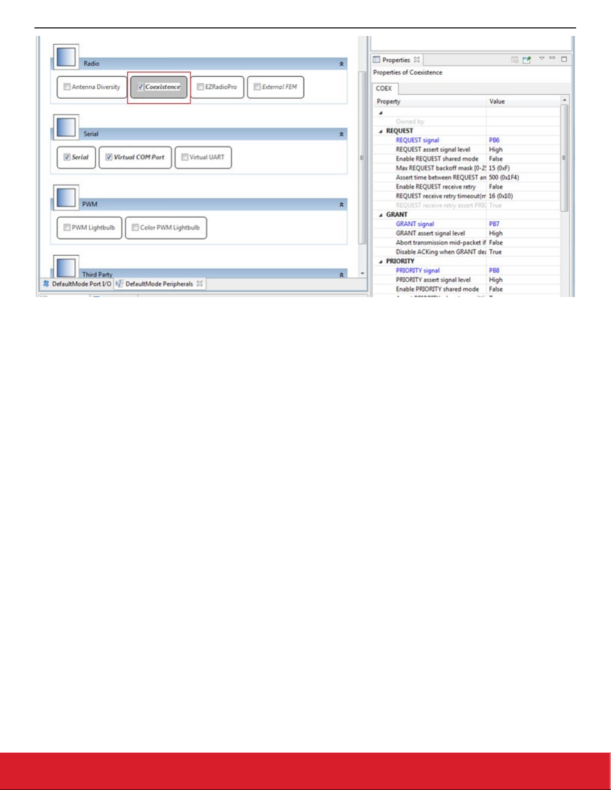
2. Open the project’s .hwconf file in Hardware Configurator and select Default Mode Peripherals view.
3. Select Coexistence in the Radio section to open coexistence properties and ensure Coexistence is enabled.
silabs.com | Building a more connected world. Rev. 2.3 | 4
Page 6
AN1017: Zigbee® and Silicon Labs® Thread Coexistence with Wi-Fi®
Configuring Wi-Fi Coexistence
Figure 2-2. Radio Coexistence Hardware Configurator
AppBuilder displays the Properties of Coexistence as shown in the following figure.
silabs.com | Building a more connected world. Rev. 2.3 | 5
Page 7

AN1017: Zigbee® and Silicon Labs® Thread Coexistence with Wi-Fi®
Configuring Wi-Fi Coexistence
Figure 2-3. Properties of Coexistence in AppBuilder
2.2. PTA Software Setup with the Component Editor (OpenThread)
The steps to set up PTA Software for OpenThread using the Component Editor are described below .These steps assume you
have installed Simplicity Studio 5 and the OpenThread SDK and that you have a project open in the Simplicity IDE.
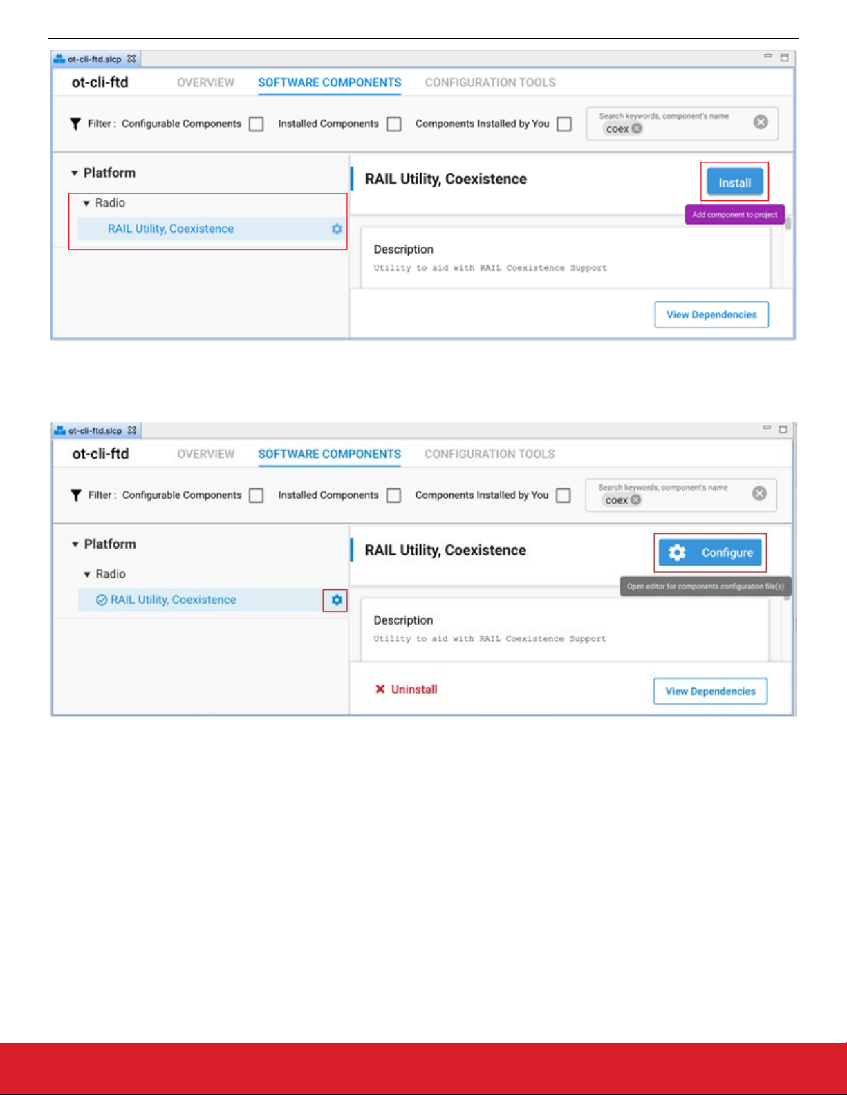
1. On the SOFTWARE COMPONENTS tab, search for coex in the ‘component’s name’ search field (at the top right).
2. Under Platform components, select the RAIL Utility Coexistence component and click Install as shown in the following figure.
silabs.com | Building a more connected world. Rev. 2.3 | 6
Page 8
AN1017: Zigbee® and Silicon Labs® Thread Coexistence with Wi-Fi®
Configuring Wi-Fi Coexistence
Figure 2-4. Install RAIL Utility, Coexistence
3. Once the Coexistence component is successfully installed, click Configure or the configure symbol next to the component name to
open the coexistence properties as shown in the following figure.
Figure 2-5. Configure RAIL Utility, Coexistence
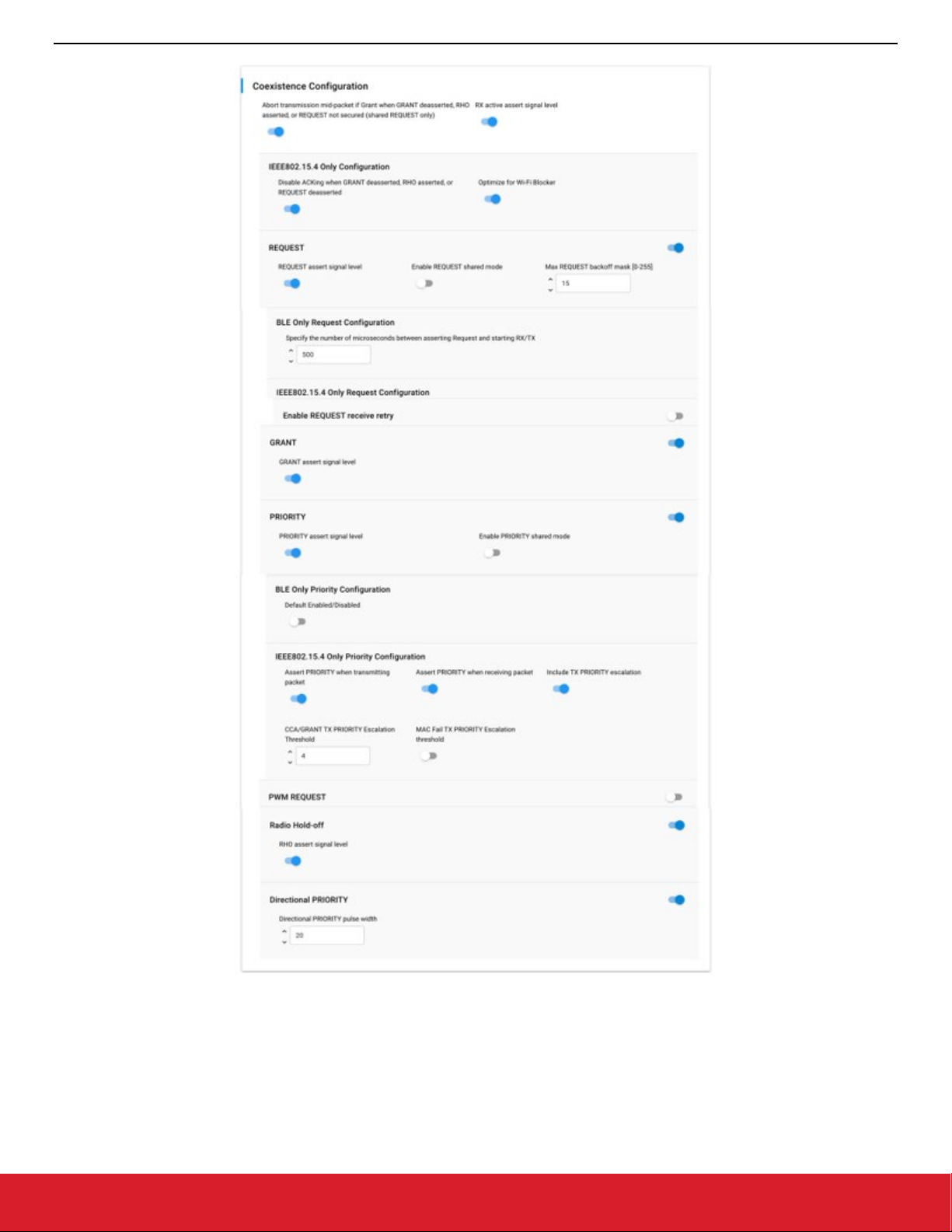
The following figure shows the different coexistence properties in the Component Editor. For more information on coexistence properties,
see 2.3 Coexistence Configurations.
silabs.com | Building a more connected world. Rev. 2.3 | 7
Page 9
AN1017: Zigbee® and Silicon Labs® Thread Coexistence with Wi-Fi®
Configuring Wi-Fi Coexistence
Figure 2-6. Coexistence Properties in the Component Editor
silabs.com | Building a more connected world. Rev. 2.3 | 8
Page 10
AN1017: Zigbee® and Silicon Labs® Thread Coexistence with Wi-Fi®
Configuring Wi-Fi Coexistence
2.3. Coexistence Configurations
The following subsections describe the coexistence configurations in detail.
Note: To configure GPIO pins for a coexistence signal in the Component Editor, use the equivalent SL_RAIL_UTIL_COEX <signal>
section of the configuration header.
2.3.1. REQUEST
REQUEST signal enabled
• If selected, REQUEST is mapped to GPIO pin and is used by PTA implementation.
• If not selected, REQUEST is not mapped to GPIO pin.
REQUEST signal is shared
• If selected. REQUEST is shared and implements open-drain or open-source I/O for multi-EFR32 radio applications.
• If active low, REQUEST is open-drain and an external 1 kΩ ±5% pull-up is required.
• If active high, REQUEST is open-source and an external 1 kΩ ±5% pull-down is required.
• If not selected, REQUEST is not shared and implements a push-pull output for single EFR32 radio applications.
REQUEST signal active high
• If selected, REQUEST GPIO pin is driven high (> Voh) when REQUEST is asserted.
• If not selected, REQUEST GPIO pin is driven low (< Vol) when REQUEST is asserted.
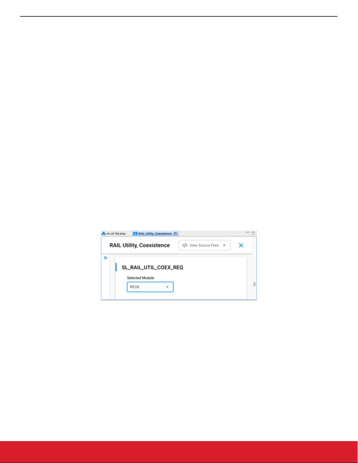
REQUEST signal GPIO port and REQUEST signal GPIO pin
• Select REQUEST port and pin matching circuit board configuration.
• To configure GPIO port and pin for the REQUEST signal in the Component Editor, use the SL_RAIL_UTIL_COEX_REQ section of
the configuration header.
Figure 2-7. REQUEST signal in the Component Editor
REQUEST signal max backoff mask [0-255]
• REQUEST signal max backoff determines the random REQUEST delay mask (only valid if REQUEST signal is shared).
• Random delay (in µs) is computed by masking the internal random variable against the entered mask.
n
• The mask should be set to a value of 2
-1 to insure a continuous random delay range.
2.3.1.1. Receive Retry
Receive retry REQUEST enabled
• If selected, REQUEST is held after a corrupted receive packet or after a successful receive packet with GRANT denied until timeout
expires or another packet is received.
Note: This feature is useful to hold 2.4 GHz band clear while the remote device re-transmits a packet, maximizing the opportunity
to receive an uncorrupted retry packet from the remote device, reducing 2.4 GHz RF traffic and improving battery life.
• If not selected, REQUEST is not held after a corrupted receive packet or after a successful receive packet with GRANT denied.
silabs.com | Building a more connected world. Rev. 2.3 | 9
Page 11
AN1017: Zigbee® and Silicon Labs® Thread Coexistence with Wi-Fi®
Configuring Wi-Fi Coexistence
Receive retry timeout (milliseconds) [0-255]
• Selects the timeout for REQUEST hold after a corrupted receive packet.
Notes:
1. 16ms is recommended to allow for maximum 802.15.4 packet duration and MAC retry random delay.
2. Many Wi-Fi/PTA implementations have a maximum GRANT timeout, which should be set to received retry timeout plus 6ms to allow
for maximum size corrupted packet, maximum random delay, and maximum size retry packet.
REQUEST high PRIORITY on receive retry
• If selected, PRIORITY is asserted during REQUEST hold after a corrupted receive packet or after a successful receive packet with
GRANT denied.
• If not selected, PRIORITY is deasserted during REQUEST hold after a corrupted receive packet or after a successful receive packet
with GRANT denied.
2.3.2. GRANT
GRANT signal enabled
• If selected, GRANT is mapped to GPIO pin and is used by PTA implementation.
• If not selected, GRANT is not mapped to GPIO pin and GRANT is always asserted.
GRANT signal active high
• If selected, GRANT is asserted when GRANT GPIO pin is high (> Vih).
• If not selected, GRANT is asserted when GRANT GPIO pin is low (< Vil).
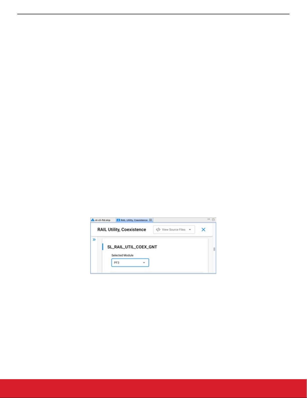
GRANT signal GPIO port and GRANT signal GPIO pin
• Select GRANT port and pin matching circuit board configuration.
• To minimize PTA impact to other EFR32 peripherals, recommended GRANT port and pin are:
• To configure GPIO port and pin for the GRANT signal in the Component Editor, use the SL_RAIL_UTIL_COEX_GNT section of the
configuration header.
Figure 2-8. GRANT signal in the Component Editor
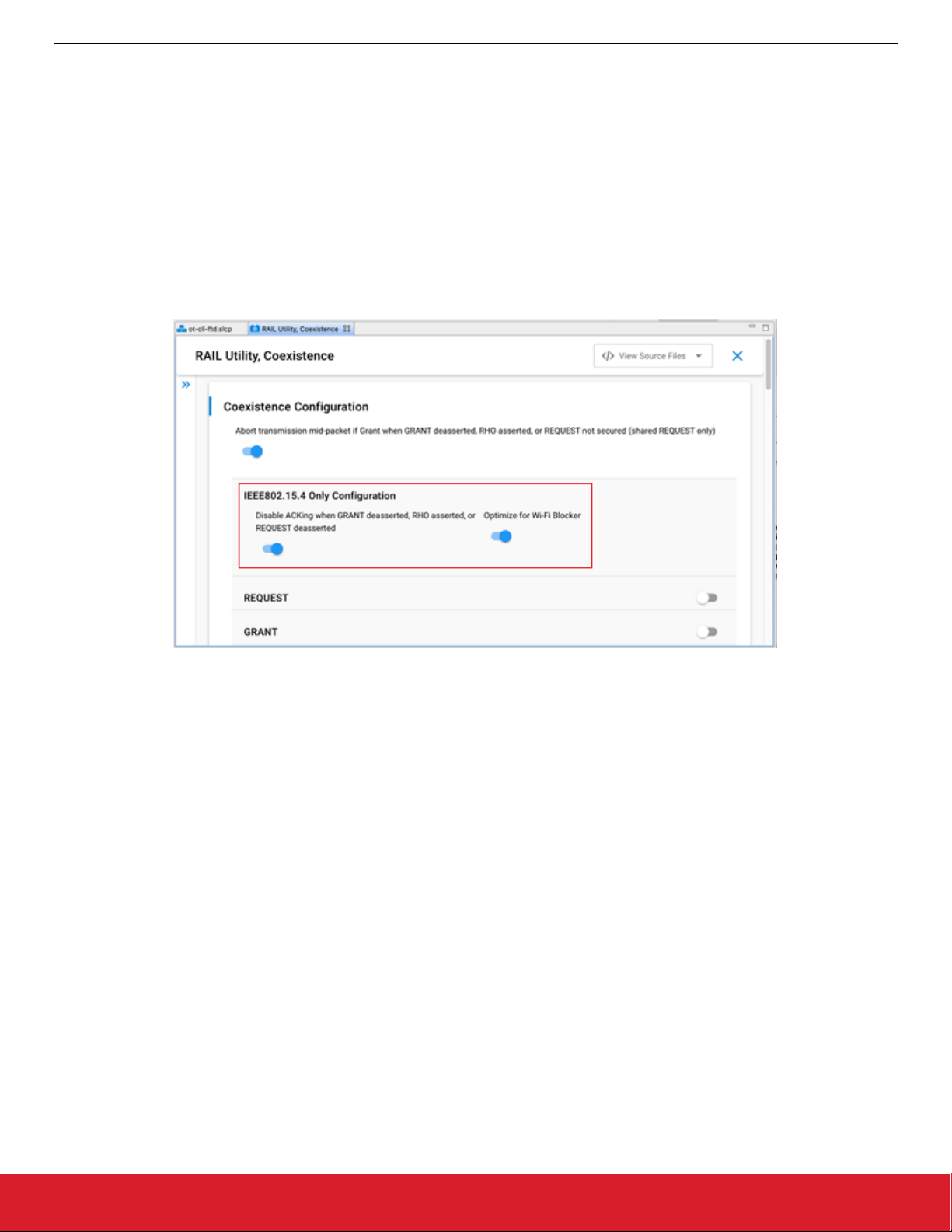
2.3.2.1. Abort Transmission Mid Packet If GRANT Is Lost
• If selected, losing GRANT during an 802.15.4 TX will abort the 802.15.4 TX.
• If not selected, losing GRANT after the initial evaluation at end of CCA will not abort the 802.15.4 TX.
Note: In the Component Editor, this option has been moved from the GRANT section to the common section of the configuration
header.
silabs.com | Building a more connected world. Rev. 2.3 | 10
Page 12
AN1017: Zigbee® and Silicon Labs® Thread Coexistence with Wi-Fi®
Configuring Wi-Fi Coexistence
2.3.2.2. ACK Disable
Disable ACKing when GRANT deasserted, RHO asserted, or REQUEST not secured (shared REQUEST only)
• If selected, the ACK to a valid RX packet, requiring an ACK, is not transmitted if GRANT is deasserted, RHO is asserted, or REQUEST
is not secured (shared REQUEST only).
Note: This feature allows completing an 802.15.4 message, regardless of PTA signals, to minimize additional retries from remote
device, reducing 2.4 GHz RF traffic and improving battery life.
• If not selected, the ACK to a valid RX packet requiring an ACK is transmitted regardless of GRANT, RHO, or REQUEST state.
Note: In the Component Editor, this option has been moved from the GRANT section to the common (IEEE802.15.4 Only Configura-
tion) section of the configuration header.
Figure 2-9. Abort Tx mid-packet and Ack Disable options in the Component Editor
2.3.3. PRIORITY
PRIORITY signal enabled
• If selected, PRIORITY is mapped to GPIO pin and is used by PTA implementation.
• If not selected, PRIORITY is not mapped to GPIO pin.
PRIORITY signal active high
• If selected, PRIORITY GPIO pin is driven high (> Voh) when PRIORITY is asserted.
• If not selected, PRIORITY GPIO pin is driven low (< Vol) when PRIORITY is asserted.
• If Enable Directional PRIORITY equals True, PRIORITY assert signal level must be set to High.
PRIORITY signal GPIO port and PRIORITY signal GPIO pin
• Select PRIORITY port and pin matching circuit board configuration.
• To configure GPIO port and pin for the PRIORITY signal in the Component Editor, use the SL_RAIL_UTIL_COEX_PRI section of
the configuration header.
silabs.com | Building a more connected world. Rev. 2.3 | 11
Page 13

AN1017: Zigbee® and Silicon Labs® Thread Coexistence with Wi-Fi®
Configuring Wi-Fi Coexistence
Figure 2-10. PRIORITY signal in the Component Editor
Enable PRIORITY shared mode
• If enabled. PRIORITY is shared and implements open-drain or open-source I/O for multi-EFR32 radio applications.
• If active low, PRIORITY is open-drain and an external 1 kΩ ±5% pull-up is required.
• If active high, PRIORITY is open-source and an external 1 kΩ ±5% pull-down is required.
• If not enabled, PRIORITY is not shared and implements a push-pull output for single EFR32 radio applications.
TX high PRIORITY
• If selected, PRIORITY is asserted during 802.15.4 TX.
• If not selected, PRIORITY is deasserted during 802.15.4 TX.
RX high PRIORITY
• If selected, PRIORITY is asserted during 802.15.4 RX.
• If not selected, PRIORITY is deasserted during 802.15.4 RX.
Include TX PRIORITY Escalation
• If enabled. TX PRIORITY Escalation feature is compiled into firmware.
• If not enabled, TX PRIORITY Escalation feature is not compiled into firmware and CCA/GRANT TX PRIORITY Escalation Threshold
and MAC Fail TX PRIORITY Escalation Threshold must be set to 0 when writing to ptaOptions via run-time API.
CCA/GRANT TX PRIORITY Escalation Threshold
• If set to 0 (000b, default):
• CCA/GRANT TX PRIORITY Escalation is disabled.
• PRIORITY during TX is asserted as per “TX high PRIORITY” setting.
• If set between n=1 (001b) to 7 (111b) [requires “TX high PRIORITY” set to low priority (0)]:
• CCA/GRANT TX PRIORITY Escalation is enabled.
• PRIORITY during TX becomes asserted high after n MAC failures due to four CCA and/or GRANT denial failures.
• PRIORITY during TX remains asserted high until a successful MAC TX and RX ACK.
MAC Fail TX PRIORITY Escalation Threshold
• If set to 0 (00b, default):
• CCA/GRANT TX PRIORITY Escalation is disabled.
• PRIORITY during TX is asserted as per “TX high PRIORITY” setting.
• If set to n=1 (01b) to 3 (11b) [requires “TX high PRIORITY” set to low priority (0)]:
• CCA/GRANT TX PRIORITY Escalation is enabled.
• PRIORITY during TX is asserted high after n MAC failures due to CCA (four CCA failures) or MAC ACK fails (four MAC TX and
RX ACK failures).
• PRIORITY during TX remains asserted high until a successful MAC TX and RX ACK.
silabs.com | Building a more connected world. Rev. 2.3 | 12
Page 14

AN1017: Zigbee® and Silicon Labs® Thread Coexistence with Wi-Fi®
Configuring Wi-Fi Coexistence
2.3.4. PWM
PWM REQUEST signal (shared REQUEST only)
• If REQUEST signal is NOT shared, PWM REQUEST signal must be set to “Disabled”.
• If REQUEST signal is shared, the REQUEST GPIO pin is used to arbitrate REQUEST between multiple EFR32 radios and a second
GPIO is required to drive REQUEST||PWM. PWM REQUEST signal specifies the REQUEST||PWM GPIO.
PWM REQUEST signal level (shared REQUEST only)
• If PWM REQUEST signal is “Disabled”, then PWM REQUEST signal level selection is ignored. Else, PWM REQUEST signal is shared
and implements open-drain or open-source I/O for multi-EFR32 radio applications.
• If active low, PWM REQUEST is open-drain, an external 1 kΩ ±5% pull-up is required, and PWM REQUEST GPIO pin is driven low
(< Vol) when REQUEST||PWM is asserted.
• If active high, PWM REQUEST is open-source, an external 1 kΩ ±5% pull-down is required, and PWM REQUEST GPIO pin is driven
high (> Voh) when REQUEST||PWM is asserted.
PWM REQUEST signal GPIO port and PWM REQUEST signal GPIO PIN
• To configure GPIO port and pin for the PWM REQUEST signal in the Component Editor, use the
SL_RAIL_UTIL_COEX_PWM_REQ section of the configuration header.
Figure 2-11. PWM REQUEST signal in the Component Editor
Enable PWM REQUEST at startup
• If enabled, PWM REQUEST is enabled at firmware startup as per specified period, duty-cycle, and priority.
• If not enabled, PWM REQUEST is enabled at firmware startup, but can be enabled via run-time API.
PWM REQUEST Period (0.5 ms)
Note: PWM REQUEST Period selection cannot be an integer sub-multiple of the Wi-Fi beacon or a significant number of consecutive
Wi-Fi beacons may be missed, causing AP to collapse Wi-Fi network or STA to disassociate. Silicon Labs achieves <1%
802.15.4 message receive loss with PWM REQUEST set to 39 ms (or 78 half-ms) period, 20% duty-cycle, and high priority,
which results in ~30% reduction in Wi-Fi TCP throughput over MCS0 to MCS7 and 20 or 40 MHz bandwidth.
• Sets PWM REQUEST Period from 5 ms (10) to 109 ms (218) in 0.5 ms steps.
PWM REQUEST Duty-Cycle (%)
Note: Large PWM REQUEST Duty-Cycle selection will substantially impact the Wi-Fi throughput as it reserved more time for 802.15.4
listening. Silicon Labs achieves <1% 802.15.4 message receive loss with PWM REQUEST set to 39 ms (or 78 half-ms) period,
20% duty-cycle, and high priority, which results in ~30% reduction in Wi-Fi TCP throughput over MCS0 to MCS7 and 20 or 40
MHz bandwidth.
• Sets PWM REQUEST Duty-Cycle from 1% to 95% in 1% steps.
Assert PRIORITY when PWM REQUEST asserted
• Sets PWM REQUEST PRIORITY to assert or not when PWM REQUEST asserts.
silabs.com | Building a more connected world. Rev. 2.3 | 13
Page 15

AN1017: Zigbee® and Silicon Labs® Thread Coexistence with Wi-Fi®
Configuring Wi-Fi Coexistence
2.3.5. Radio Hold Off
RHO (Radio Hold Off) signal enabled
• If selected, RHO is mapped to GPIO pin and is used by PTA implementation.
• If not selected, RHO is not mapped to GPIO pin and RHO is always deasserted.
RHO (Radio Hold Off) active high
• If selected, RHO is asserted when RHO GPIO pin is high (> Vih).
• If not selected, RHO is asserted when RHO GPIO pin is low (< Vil).
RHO (Radio Hold Off) signal GPIO port and RHO (Radio Hold Off) signal GPIO pin
• Select RHO port and pin matching circuit board configuration.
• To configure GPIO port and pin for the RHO signal in the Component Editor, use the SL_RAIL_UTIL_COEX_RHO section of the
configuration header.
Figure 2-12. Radio Hold Off signal in the Component Editor
2.3.6. Directional PRIORITY
Enable Directional PRIORITY
• If True:
• Directional PRIORITY signal is connected to the Wi-Fi PTA and multiplexes priority state and radio state information.
• Allows the Wi-Fi PTA master to obtain radio state information from the EFR32 using the Directional PRIORITY signal.
• When requesting network airtime, the EFR32 will assert a pulse on the Directional PRIORITY line depending on the requirement
of that transaction and then switch to communicating the state of the radio on the same Directional PRIORITY line.
• The Directional PRIORITY line is held low when the radio is in receive mode and is held high when the radio is in transmit mode.
• The PRIORITY signal is not assigned a GPIO and is set to Disabled, has no physical connection to the Wi-Fi PTA and is used as
Static PRIORITY input to the Directional PRIORITY logic block with the remaining PRIORITY signal configuration options described in section 2.3.3 PRIORITY applied.
Note: Hardware Configurator PRIORITY configuration fields are disabled and therefore not editable when Enable Directional
PRIORITY is set to True. A workaround is to assign any GPIO to PRIORITY signal, edit the PRIORITY configuration
options, and then set PRIORITY signal to Disabled.
• If False:
• The Directional PRIORITY signal is not used or connected to the Wi-Fi PTA.
• The PRIORITY signal is connected to the Wi-Fi PATA and operates as Static PRIORITY and is either high or low during REQUEST
asserted for the transmit or receive operation.
Directional PRIORITY Timer (Zigbee)
To configure the Directional PRIORITY Timer in AppBuilder:
1. Choose an unused Timer. TIMER1 is recommended for most EmberZNet PRO applications because TIMER0 is used by the IEEE
802.15.4 software stacks.
silabs.com | Building a more connected world. Rev. 2.3 | 14
Page 16

AN1017: Zigbee® and Silicon Labs® Thread Coexistence with Wi-Fi®
Configuring Wi-Fi Coexistence
Figure 2-13. Directional PRIORITY Timer in AppBuilder
2. For EFR32xG2x devices, the Timer Compare / Capture Channel is selected by the stack code. However, for EFR32xG1x devices,
the stack code does not select the Timer Compare / Capture Channel pin. Follow the steps below to select the Timer Compare /
Capture Channel pin for EFR32xG1x devices.
1. Select the Timer Compare / Capture Channel pin.
2. Open Hardware Configurator.
3. Open the corresponding .hwconf file for the application being built.
4. On the Configurator tab, select the Default Mode Peripherals view.
5. Select the same TIMERx as selected in the Directional PRIORITY section of the coexistence plugin. TIMER1 is shown in this
example but any available Timer can be used.
Figure 2-14. Timer option in Hardware Configurator
3. Change the TIMER Compare/Capture Channel 0 pin to match the same GPIO pin used for REQUEST.
PC10 is shown in this example but other GPIOs can be selected. Refer to the EFR32 datasheet or reference manual to confirm GPIO
availability for the TIMERx Compare/Capture Channel 0 pin.
Figure 2-15. GPIO configurations for REQUEST and TIMER signals
Directional PRIORITY Timer (OpenThread)
To configure the Directional PRIORITY Timer in the Component Editor:
1. Use the SL_RAIL_UTIL_COEX_DP_TIMER to choose an unused timer,
2. Set the TIMER Compare/Capture Channel 0 (CC0) pin to match the same GPIO pin used for REQUEST.
silabs.com | Building a more connected world. Rev. 2.3 | 15
Page 17

AN1017: Zigbee® and Silicon Labs® Thread Coexistence with Wi-Fi®
Configuring Wi-Fi Coexistence
Figure 2-16. Directional PRIORITY Timer in the Component Editor
Note: For EFR32xG2x devices, the Timer Compare / Capture Channel is selected by the stack code. However, for EFR32xG1x
devices, the stack code does not select the Timer Compare / Capture Channel pin.
Directional PRIORITY Pulse Width [0-255]
• Set to 20 (0x14) by default.
• Selects the hold time of the Directional PRIORITY RX Priority pulse in microseconds for a range of 1 to 255 depending on the
requirement of the Wi-Fi PTA. Silicon Labs recommends the default of 20 microseconds for typical Wi-Fi PTA implementations.
• Set to 0 to bypass Directional PRIORITY.
Directional Priority PRS Channel
To configure the Directional PRIORITY PRS Channel:
1. Choose any group of four PRS channels not currently used by the SDK stack software, other plugins, or custom code.
2. Assign the highest PRS channel number from this group to the Directional Priority PRS Channel value.
Note: The External FEM plugin is recommended to be enabled for monitoring the EFR32 radio TX activity and radio RX
activity for the custom coexistence application test and development purposes and can use up to two additional PRS
channels.
The SDK stack software automatically selects the preceding three PRS channels from the group.
Example: Designer selects PRS channel 2 as the Directional Priority PRS Channel value. From the designer’s choice, the SDK stack
software automatically selects PRS channel 1, PRS channel 0 and PRS channel 11 for use in the Directional Priority PRS Channel
group. In this example, the SDK stack software automatically wraps around from the lowest PRS channel number to the highest PRS
channel number until all three additional required PRS channels are assigned.
To configure the Directional PRIORITY PRS Channel in SSv5 Component Editor:
1. Use the SL_RAIL_UTIL_COEX_DP_OUT section of the configuration header.
2. Selecting the Directional PRIORITY PRS Channel displays the PRS Channel Output Pin configuration option.
Figure 2-17. Directional PRIORITY PRS Channel and Port Pin Configuration in the Component Editor
PRS Channel Output Pin
• Directional PRIORITY output GPIO pin
• Connects to the Wi-Fi PTA.
silabs.com | Building a more connected world. Rev. 2.3 | 16
Page 18

AN1017: Zigbee® and Silicon Labs® Thread Coexistence with Wi-Fi®
Configuring Wi-Fi Coexistence
Inverted Request PRS Channel
For EFR32xG2x Series 2 EFR32 devices, the Inverted Request PRS Channel is selected by the stack code. However, the stack code
does not select the Inverted Request PRS Channel for EFR32xG1x Series 1 EFR32 devices.
• Choose any PRS channel not used by the SDK stack software, other plugins, custom code, or the Directional Priority PRS Channel
option.
• For EFR32xG2x, leave this option Disabled.
• To configure the Inverted Request PRS Channel in the Component Editor, use the SL_RAIL_UTIL_COEX_DP_REQUEST_INV sec-
tion of the configuration header.
Figure 2-18. Inverted Request PRS Channel in the Component Editor
2.3.7. Radio Blocker Optimization
Notes
1. Radio Blocker Optimization is available for applications using Zigbee EmberZNet PRO and OpenThread and is available only for
EFR32xG12, EFR32xG13 and EFR32xG14 EFR32 devices. Radio Blocker Optimization is not available for all other EFR32xG variants.
2. It is highly recommended to enable Radio Blocker Optimization on EFR32xG12, EFR32xG13 and EFR32xG14 devices when co-
located with a Wi-Fi device such as in a Gateway.
3. For Zigbee EmberZNet PRO 6.x, runtime control of Radio Blocker Optimization can be enabled in the Hardware Configurator. Wi-
Fi control of Radio Blocker Optimization is optionally enabled in the Hardware Configurator when runtime control is enabled.
4. For OpenThread, the Radio Blocker Optimization and Run time control of Radio Blocker Optimization features are supported
using the SL_RAIL_UTIL_COEX_PHY_ENABLED and SL_RAIL_UTIL_COEX_RUNTIME_PHY_SELECT configuration options
defined in sl_rail_util_coex_config.h.
Optimize for Wi-Fi Blocker (Zigbee) / SL_RAIL_UTIL_COEX_PHY_ENABLED (OpenThread)
• If True:
• IEEE802.15.4 PHY performs better in the presence of Wi-Fi interference through improved adjacent channel rejection and far
channel rejection.
• IEEE802.15.4 PHY performance is slightly reduced in the presence of 802.15.4 and other narrow-band interferers.
• If False: IEEE 802.15.4 PHY is optimized for narrow-band interference, resulting in reduced adjacent channel rejection and far channel
rejection performance in the presence of Wi-Fi interference.
This setting can be overridden by the Enable Runtime Control setting.
2.3.7.1. Enable Runtime Control (Zigbee) / SL_RAIL_UTIL_COEX_RUNTIME_PHY_SELECT (OpenThread)
• If True: runtime control of Wi-Fi Blocker Optimization is available.
• If False: runtime control of Wi-Fi Blocker Optimization is not available.
2.3.7.2. Optional “Wi-Fi Select” Control of Blocker Optimization (Zigbee) / SL_RAIL_UTIL_COEX_PHY_SELECT (OpenThread)
Note: The run-time Wi-Fi blocker optimization selection may block proper Zigbee operation and should not be used. This issue will be
corrected in a future SDK release. Compile-time selection of Wi-Fi blocker optimization always enabled or disabled works correctly.
silabs.com | Building a more connected world. Rev. 2.3 | 17
Page 19

AN1017: Zigbee® and Silicon Labs® Thread Coexistence with Wi-Fi®
Configuring Wi-Fi Coexistence
• Selects the GPIO port and pin – defaults to Disabled.
• The selected GPIO pin is connected to Wi-Fi PA enable pin.
• This feature is not available if Enable Runtime Control/ SL_RAIL_UTIL_COEX_RUNTIME_PHY_SELECT is False.
PHY SELECT assert signal level (Zigbee) / SL_RAIL_UTIL_COEX_PHY_SELECT_ASSERT_LEVEL (OpenThread)
• Assert high if Wi-Fi PA Enable is active high.
• Assert low if Wi-Fi PA Enable is active low.
PHY SELECT timeout ms (Zigbee) / SL_RAIL_UTIL_COEX_DEFAULT_PHY_SELECT_TIMEOUT ms (OpenThread)
• 0 = (Default) Optimize for Wi-Fi Blocker = false and is always optimized for narrow band interferers. The GPIO state is ignored.
• 255 = Optimize for Wi-Fi Blocker = true and is always optimized for co-located Wi-Fi. The GPIO state is ignored.
• If 1 - 254 and GPIO is defined:
• Wi-Fi Blocker Optimization is initially set per the assert state of the PHY SELECT assert signal level GPIO.
• If GPIO is asserted, Optimize for Wi-Fi Blocker is enabled and the 802.15.4 PHY is optimized for Wi-Fi interferers.
• If GPIO is not asserted, Optimize for Wi-Fi Blocker is disabled and the 802.15.4 PHY is optimized for narrow band interferers.
• Wi-Fi’s PA Enable assert triggers the Wi-Fi Blocker Optimization.
• Wi-Fi’s PA Enable de-assert triggers the countdown in milliseconds (1-254). When the countdown completes, the Optimize for
Wi-Fi Blocker option is set to false.
2.3.8. RX Active
Notes:
1. The RX Active feature passes the 802.15.4 MODEM_FRAME_DETECT radio signal to a GPIO pin using a PRS channel. In Ap-
pBuilder, the GPIO port, pin, and assert level are selected in Hardware Configurator. The signal output from the selected GPIO is
then used to drive the RHO pin on other radios.
2. To configure the GPIO port, pin, and assert level in the Component Editor use the SL_RAIL_UTIL_COEX_RX_ACTIVE section of
the configuration header as shown in the following figure.
Figure 2-19. RX Active PRS Channel and Port/Pin Configuration in the Component Editor
RX active PRS channel
• Selects PRS channel used to assign MODEM_FRAME_DETECT signal to an output GPIO.
PRS channel output pin
• Choose the GPIO to output the MODEM_FRAME_DETECT signal.
RX active assert signal level
• Selecting High results in a high signal output when the receive packet is detected and a low output otherwise.
• Selecting Low results in a low signal output when the receive packet is detected and a high output otherwise.
This completes the Coexistence Configurator setup. In AppBuilder, complete other AppBuilder application setups and generate. The
coexistence configuration is saved in the application’s .h file. When working in the Component Editor, the configurations are automatically
saved and the generate step is not required. The coexistence configurations are saved in sl_rail_util_coex_config.h and
sl_rail_util_coex_common_config.h
silabs.com | Building a more connected world. Rev. 2.3 | 18
Page 20

AN1017: Zigbee® and Silicon Labs® Thread Coexistence with Wi-Fi®
Configuring Wi-Fi Coexistence
2.4. Run-Time PTA Re-configuration
The following PTA options, which can be configured at compile time, can also be re-configured at run-time:
• Receive retry timeout (milliseconds) [0-255]
• Disable ACKing when GRANT deasserted, RHO asserted, or REQUEST not secured (shared REQUEST only)
• Abort transmission mid packet if GRANT is lost
• TX high PRIORITY
• RX high PRIORITY
• REQUEST high PRIORITY on receive retry
• Receive retry REQUEST enabled
• RHO (Radio Hold Off) signal enabled
• CCA/GRANT TX PRIORITY Escalation Threshold
• MAC Fail TX PRIORITY Escalation Threshold
• PWM REQUEST
For descriptions of the above PTA options fields, see 2.4.1 PTA Option Descriptions
.
The following PTA options cannot be configured via AppBuilder and can only be configured at run-time:
• Enable or disable PTA
• Disable REQUEST (force holdoff)
• Synch MAC to GRANT (MAC holdoff)
• REQUEST/PRIORITY Assert (Preamble/Synch or Address Detection)
For OpenThread using the Component Editor, the Synch MAC to GRANT (MAC holdoff) option has been added as a configuration
option under the OpenThread Platform Abstraction component so you can configure it at compile time. This requires that you have
already installed the Rail Utility, Coexistence component as a part of your project.
Figure 2-20. Synch MAC to GRANT (MAC holdoff) option for OpenThread in the Component Editor
2.4.1. PTA Option Descriptions
The descriptions of the above PTA options fields follow.
Disable REQUEST (force holdoff)
• If not set (default), REQUEST operates per the description in UG103.17: Wi-Fi® Coexistence Fundamentals.
• If set, REQUEST stays disabled, effectively halting all radio TX/RX functions.
Synch MAC to GRANT (MAC holdoff)
• If not set (default), Synch MAC to GRANT is disabled for 802.15.4-compliant random MAC delays.
• If set, MAC CCA/TX is delayed until GRANT is asserted, synching all TX operations with GRANT.
• Synch MAC to GRANT is not strictly 802.15.4 compliant as it prevents random MAC delay execution.
• Synch MAC to GRANT should only be enabled during known, higher priority, Wi-Fi or BT interfering activity and disabled as soon
as such activity completes.
silabs.com | Building a more connected world. Rev. 2.3 | 19
Page 21

AN1017: Zigbee® and Silicon Labs® Thread Coexistence with Wi-Fi®
PTA Feature
Bit Position
Size (bits)
REQUEST high PRIORITY on receive retry
12
1
Configuring Wi-Fi Coexistence
REQUEST/PRIORITY Assert (Preamble/Synch or Address Detection)
• If set to 0 (00b, default and recommended):
• REQUEST during RX is asserted at Preamble/Synch.
• PRIORITY during RX is asserted at Preamble/Synch, as per “RX high PRIORITY” setting.
• If set to 1 (01b) or 3 (11b) [requires “RX high PRIORITY” set to high priority (1)]:
• REQUEST during RX is asserted at Address Detection (for this radio).
• PRIORITY during RX is asserted at Address Detection (for this radio).
• If set to 2 (10b) [requires “RX high PRIORITY” set to low priority (0)]:
• REQUEST during RX is asserted at Preamble/Synch.
• PRIORITY during RX is asserted at Address Detection (for this radio).
Notes:
1. For Zigbee, the API function calls for re-configuring coexistence PTA vary based on SoC or EZSP application.
2. For OpenThread, the API functions for re-configuring coexistence PTA is currently supported on SoC only.
3. For Run-Time API options not supported by selected EmberZNet PRO or OpenThread releases, the corresponding ptaOptions bit
fields are RESERVED and must be written to 0.
2.4.2. Application API (Zigbee)
To avoid warnings and errors at build time associated with the API function calls in this section, add the following # include into the
application's <xxx>-callbacks.c file.
#include "platform/radio/rail_lib/plugin/coexistence/protocol/ieee802154/coexistence-802154.h";
2.4.2.1. SoC Application API (Zigbee)
The following two SoC API function calls enable and disable the PTA at run-time:
bool halPtaIsEnabled(void);
EmberStatus halPtaSetEnable(bool enabled);
The following two SoC API function calls re-configure the PTA at run-time:
HalPtaOptions halPtaGetOptions(void);
EmberStatus halPtaSetOptions(HalPtaOptions options);
Where HalPtaOptions is a uint32_t with the following bitmap definition.
Receive retry timeout (milliseconds) [0-255] 0 8
Disable ACKing when GRANT deasserted, RHO asserted, or REQUEST not secured
8 1
(shared REQUEST only)
Abort transmission mid packet if GRANT is lost 9 1
TX high PRIORITY 10 1
RX high PRIORITY 11 1
RHO (Radio Hold Off) signal enabled 14 1
Reserved (Reserved bits MUST be written 0) 15 1
Disable REQUEST (force holdoff) 16 1
Synch MAC to GRANT (MAC holdoff) 17 1
REQUEST/PRIORITY Assert (Preamble/Synch or Address Detection) 18 2
CCA/GRANT TX PRIORITY Escalation Threshold 20 3
silabs.com | Building a more connected world. Rev. 2.3 | 20
Page 22

AN1017: Zigbee® and Silicon Labs® Thread Coexistence with Wi-Fi®
PTA Feature
Bit Position
Size (bits)
Configuring Wi-Fi Coexistence
Reserved (Reserved bits MUST be written 0) 23 2
MAC Fail TX PRIORITY Escalation Threshold 25 2
Reserved (Reserved bits MUST be written 0) 27 5
The following two SoC API function calls re-configure the PWM REQUEST at run-time:
const HalPtaPwmArgs_t *halPtaGetRequestPwmArgs(void);
EmberStatus halPtaSetRequestPwm(halPtaReq_t ptaReq, halPtaCb_t ptaCb, uint8_t dutyCycle, uint8_t
periodHalfMs);
Where:
typedef struct HalPtaPwmArgs {
halPtaReq_t req;
uint8_t dutyCycle;
uint8_t periodHalfMs;
} HalPtaPwmArgs_t;
and
ptaReq/req: 0x00 => PWM REQUEST disabled
0x80 => PWM REQUEST enabled at low priority
0x82 => PWM REQUEST enabled at high priority
ptaCb: NULL
dutyCycle: PWM REQUEST duty-cycle from 5% to 95% in 1% steps
periodHalfMs: PWM REQUEST Period from 5 ms (10) to 109 ms (218) in 0.5 ms steps
The following two SoC API function calls re-configure the Directional PRIORITY at run-time:
dp_pulse = halPtaGetDirectionalPriorityPulseWidth();
halPtaSetDirectionalPriorityPulseWidth(dp_pulse);
Where:
uint8_t dp_pulse: Pulse width (0 to disable, 1-255µs)
When multiple EFR32s are connected to Wi-Fi/PTA, TX PRIORITY Escalation can be controlled at run-time via "CCA/GRANT TX
PRIORITY Escalation Threshold" and "MAC Fail TX PRIORITY Escalation Threshold" fields of PTA Options. When using this feature,
"TX high PRIORITY" field must be set to 0 to avoid driving PRIORITY high on all TX messages.
2.4.2.2. Zigbee Network Coprocessor Application using EZSP API
The following two EZSP (EmberZNet Serial Protocol) API function calls enable and disable the PTA, re-configure the PTA, and reconfigure
the PWM REQUEST at run-time:
EzspStatus ezspGetValue(EzspValueId valueId, uint8_t *valueLength, uint8_t *value);
EzspStatus ezspSetValue(EzspValueId valueId, uint8_t valueLength, uint8_t *value);
Where valueId and valueLength have the following PTA related options.
EZSP Value ID Value
EZSP_VALUE_ENABLE_PTA 0x31 1
EZSP_VALUE_PTA_OPTIONS 0x32 4
EZSP_VALUE_PTA_PWM_OPTIONS 0x35 3 Configure PWM REQUEST options.
EZSP_VALUE_PTA_DIRECTIONAL_PRIORITY_PULSE_WIDTH 0x36 1 Pulse width (0 to disable, 1-255µs)
Length
(bytes)
Description
Enable (1) or disable (0) packet traffic
arbitration.
Set packet traffic arbitration (PTA)
configuration options.
silabs.com | Building a more connected world. Rev. 2.3 | 21
Page 23

AN1017: Zigbee® and Silicon Labs® Thread Coexistence with Wi-Fi®
PTA Feature
Bit Position
Size (bits)
RHO (Radio Hold Off) signal enabled
14
1
Reserved (Reserved bits MUST be written 0)
15
1
Configuring Wi-Fi Coexistence
Where PTA configuration options are a uint32_t with the following bitmap definition.
Receive retry timeout (milliseconds) [0-255] 0 8
Disable ACKing when GRANT deasserted, RHO asserted, or REQUEST not secured
(shared REQUEST only)
Abort transmission mid packet if GRANT is lost 9 1
TX high PRIORITY 10 1
RX high PRIORITY 11 1
REQUEST high PRIORITY on receive retry 12 1
Receive retry REQUEST enabled 13 1
Disable REQUEST (force holdoff) 16 1
Synch MAC to GRANT (MAC holdoff) 17 1
REQUEST/PRIORITY Assert (Preamble/Synch or Address Detection) 18 2
CCA/GRANT TX PRIORITY Escalation Threshold (requires additional application
code)
Reserved (Reserved bits MUST be written 0) 23 2
MAC Fail TX PRIORITY Escalation Threshold (requires additional application code) 25 2
Reserved (Reserved bits MUST be written 0) 27 5
8 1
20 3
PWM REQUEST configuration options is a three-byte uint8_t array:
{uint8_t ptaReq, uint8_t dutyCycle, uint8_t periodHalfMs}
Where:
ptaReq: 0x00 => PWM REQUEST disabled
0x80 => PWM REQUEST enabled at low priority
0x82 => PWM REQUEST enabled at high priority
dutyCycle: PWM REQUEST duty-cycle from 5% to 95% in 1% steps
periodHalfMs: PWM REQUEST Period from 5 ms (10) to 109 ms (218) in 0.5 ms steps
and the Directional PRIORITY parameter is:
uint8_t dp_pulse: Pulse width (0 to disable, 1-255µs)
When multiple EFR32s are connected to Wi-Fi/PTA, TX PRIORITY Escalation can be controlled at run-time via "CCA/GRANT TX
PRIORITY Escalation Threshold" and "MAC Fail TX PRIORITY Escalation Threshold" fields of PTA Options. When using this feature,
"TX high PRIORITY" field must be set to 0 to avoid driving PRIORITY high on all TX messages.
2.4.3. Application API (OpenThread)
To avoid warnings and errors at build time associated with the API function calls in this section, add the following # include into the
application's <xxx>-callbacks.c file.
#include "platform/radio/rail_lib/plugin/coexistence/protocol/ieee802154_uc/coexistence-802154.h";
2.4.3.1. SoC Application API (OpenThread)
The following two SoC API function calls enable and disable the PTA at run-time:
bool sl_rail_util_coex_is_enabled(void;
sl_status_t sl_rail_util_coex_set_enable(bool enabled);
The following two SoC API function calls re-configure the PTA at run-time:
silabs.com | Building a more connected world. Rev. 2.3 | 22
Page 24

AN1017: Zigbee® and Silicon Labs® Thread Coexistence with Wi-Fi®
PTA Feature
Bit Position
Size (bits)
RHO (Radio Hold Off) signal enabled
14
1
Reserved (Reserved bits MUST be written 0)
23
2
Configuring Wi-Fi Coexistence
sl_rail_util_coex_options_t sl_rail_util_coex_get_options(void);
sl_status_t sl_rail_util_coex_set_options(sl_rail_util_coex_options_t options);
Where sl_rail_util_coex_options_t is a uint32_t with the following bitmap definition.
Receive retry timeout (milliseconds) [0-255] 0 8
Disable ACKing when GRANT deasserted, RHO asserted, or REQUEST not secured
(shared REQUEST only)
Abort transmission mid packet if GRANT is lost 9 1
TX high PRIORITY 10 1
RX high PRIORITY 11 1
REQUEST high PRIORITY on receive retry 12 1
Reserved (Reserved bits MUST be written 0) 15 1
Disable REQUEST (force holdoff) 16 1
Synch MAC to GRANT (MAC holdoff) 17 1
REQUEST/PRIORITY Assert (Preamble/Synch or Address Detection) 18 2
CCA/GRANT TX PRIORITY Escalation Threshold 20 3
8 1
MAC Fail TX PRIORITY Escalation Threshold 25 2
Reserved (Reserved bits MUST be written 0) 27 5
The following two SoC API function calls re-configure the PWM REQUEST at run-time:
const sl_rail_util_coex_pwm_args_t *sl_rail_util_coex_get_request_pwm_args(void);
sl_status_t sl_rail_util_coex_set_request_pwm (sl_rail_util_coex_req_t ptaReq,
sl_rail_util_coex_cb_t ptaCb, uint8_t dutyCycle, uint8_t periodHalfMs);
Where:
typedef struct sl_rail_util_coex_pwm_args {
COEX_Req_t req;
uint8_t dutyCycle;
uint8_t periodHalfMs;
} sl_rail_util_coex_pwm_args_t;
and
ptaReq/req: 0x00 => PWM REQUEST disabled
0x80 => PWM REQUEST enabled at low priority
0x82 => PWM REQUEST enabled at high priority
ptaCb: NULL
dutyCycle: PWM REQUEST duty-cycle from 5% to 95% in 1% steps
periodHalfMs: PWM REQUEST Period from 5 ms (10) to 109 ms (218) in 0.5 ms steps
The following two SoC API function calls re-configure the Directional PRIORITY at run-time:
uint8_t sl_rail_util_coex_get_directional_priority_pulse_width(void);
sl_status_t sl_rail_util_coex_set_directional_priority_pulse_width(uint8_t pulseWidthUs);
Where:
pulseWidthUs: Pulse width (0 to disable, 1-255µs)
When multiple EFR32s are connected to Wi-Fi/PTA, TX PRIORITY Escalation can be controlled at run-time via "CCA/GRANT TX
PRIORITY Escalation Threshold" and "MAC Fail TX PRIORITY Escalation Threshold" fields of PTA Options. When using this feature,
"TX high PRIORITY" field must be set to 0 to avoid driving PRIORITY high on all TX messages.
silabs.com | Building a more connected world. Rev. 2.3 | 23
Page 25

AN1017: Zigbee® and Silicon Labs® Thread Coexistence with Wi-Fi®
Configuring Wi-Fi Coexistence
2.5. Coexistence Configuration Setup Examples for Different Wi-Fi/PTA Applications (Zigbee)
Example 1: Configure EFR32 PTA support to operate as single EFR32 with typical 3-Wire Wi-Fi/PTA
• Single EFR32 radio
• RHO unused
• REQUEST unshared, active high, PC10
• Compatible 3-Wire Wi-Fi PTA devices sometimes refer to this signal as RF_ACTIVE or BT_ACTIVE (active high).
• GRANT, active low, PF3
• Compatible 3-Wire Wi-Fi PTA devices sometimes refer to this signal as WLAN_DENY (deny is active high, making grant active
low).
• PRIORITY, active high RX and TX (escalation disabled), PD12
• Compatible 3-Wire W-Fi PTA devices sometimes refer to this signal as RF_STATUS or BT_STATUS (active high).
Note: PRIORITY is static, not directional. If operated with a 3-Wire PTA expecting directional:
• Static high PRIORITY is interpreted as high PRIORITY and always in TX mode, regardless of actual TX or RX.
• Static low PRIORITY is interpreted as low PRIORITY and always in RX mode, regardless of actual TX or RX.
• PWM REQUEST disabled.
• Other options enabled to maximize 802.15.4 performance:
• 802.15.4 RX and TX both at high priority
• Receive retry REQUEST enabled with 16ms timeout and high priority.
• Enabled ACKing when GRANT deasserted.
Figure 2-21. EFR32 PTA Support Configured to Operate as Single EFR32 with Typical 3-Wire W-Fi PTA
silabs.com | Building a more connected world. Rev. 2.3 | 24
Page 26

AN1017: Zigbee® and Silicon Labs® Thread Coexistence with Wi-Fi®
Configuring Wi-Fi Coexistence
The logic analyzer capture in the following figure shows the PTA interface, Wi-Fi radio state, and EFR32 radio state for an EFR32 radio
configured for typical 3-Wire Wi-Fi/PTA.
Figure 2-22. Example 802.15.4 TX for Single EFR32 typical 3-Wire Wi-Fi/PTA Logic Analyzer Capture
Where:
• REQUEST: active high, push-pull REQUEST output
• nGRANT: active low GRANT input
• PRIORITY: active high PRIORITY output
• TXA: EFR32 FEM TX Active control signal (configured via FEM Control plugin)
• RXA: EFR32 FEM RX Active control signal (configured via FEM Control plugin)
• FRC_DFRAME: EFR32 Frame Control Data Frame signal (packet trace frame/synch)
• FRC_DOUT: EFR32 Frame Control Data Out signal (packet trace data)
• WiFi_TXA: Wi-Fi TX Active signal
This logic analyzer sequence shows:
1. Wi-Fi starts a transmit but is immediately pre-empted (WiFi_TXA pulse) by higher priority 802.15.4 transmit asserting REQUEST and
PRIORITY.
2. GRANT is asserted by Wi-Fi/PTA.
3. EFR32 radio completes CCA and CCA passes and GRANT is asserted.
4. EFR32 radio proceeds with transmit (RXA deasserts, followed by TXA assert).
5. After transmitting, EFR32 waits for ACK (TXA deasserts, followed by RXA assert).
6. EFR32 receives ACK (second FRC_DFRAME pulse). <= 802.15.4 TX message successfully completed
7. EFR32 deasserts PRIORITY and REQUEST.
8. Wi-Fi/PTA deasserts GRANT.
silabs.com | Building a more connected world. Rev. 2.3 | 25
Page 27

AN1017: Zigbee® and Silicon Labs® Thread Coexistence with Wi-Fi®
Configuring Wi-Fi Coexistence
Example 2: Configure EFR32 PTA support to operate with multi-radio 2-Wire Wi-Fi/PTA with active-low REQUEST
• Multiple EFR32 radios (external 1 kΩ ±5% pull-up required on REQUEST)
• RHO unused
• REQUEST shared, active Low, PC10
• GRANT, active Low, PF3
• PRIORITY unused
• PWM REQUEST disabled
• Other option settings to maximize 802.15.4 performance:
• Enable REQUEST to receive retry with 16ms timeout.
• Do not Disable (Enable) ACKing when GRANT is deasserted RHO asserted, REQUEST not secured.
Figure 2-23. EFR32 PTA Support Configures to Operate with Multi-radio 2-Wire Wi-Fi/PTA with active-low REQUEST
The logic analyzer capture in the following figure shows the PTA interface, Wi-Fi radio state, and EFR32 radio state for an EFR32 radio
configured for multi-radio 2-Wire PTA with active-low REQUEST:
Figure 2-24. Example 802.15.4 RX for Multi-EFR32 2-Wire Wi-Fi/PTA with active-low REQUEST Logic Analyzer Capture
silabs.com | Building a more connected world. Rev. 2.3 | 26
Page 28

AN1017: Zigbee® and Silicon Labs® Thread Coexistence with Wi-Fi®
Configuring Wi-Fi Coexistence
Where:
• nREQUEST: active low, shared (open-drain) REQUEST input/output
• nGRANT: active low GRANT input
• TXA: EFR32 FEM TX Active control signal (configured via FEM Control plugin)
• RXA: EFR32 FEM RX Active control signal (configured via FEM Control plugin)
• FRC_DFRAME: EFR32 Frame Control Data Frame signal (packet trace frame/synch)
• FRC_DOUT: EFR32 Frame Control Data Out signal (packet trace data)
• nWiFi_RXA: Wi-Fi RX Active signal
• WiFi_TXA: Wi-Fi TX Active signal
This logic analyzer sequence shows:
1. 802.15.4 packet is detected (FRC_DFRAME asserted) while Wi-Fi is receiving a packet (nWiFi_RXA asserted).
2. Shared REQUEST signal is tested and found not asserted by another EFR32 radio, so receiving EFR32 radio asserts REQUEST.
3. Wi-Fi ACK is transmitted (WiFi-TXA asserted) during 802.15.4 receive (no Wi-Fi TX pre-emption or higher priority Wi-Fi activity).
4. After Wi-Fi ACK completes, GRANT is asserted by Wi-Fi/PTA.
5. 802.15.4 receive is completed but CRC failed as packet was corrupted by co-located Wi-Fi ACK transmit during receive.
6. Since PTA configured with Receive retry REQUEST enabled using 16ms timeout, REQUEST is held up to 16ms for 802.15.4 retry
with 2.4 GHz quiet (Wi-Fi held off).
7. Wi-Fi continues to receive packets (nWiFi_RXA asserts) but does not ACK while 802.15.4 radio has GRANT.
8. After 3.5 ms gap for end-node ACK timeout and MAC random delay, the 802.15.4 retry packet arrives and is received without error.
9. 802.15 ACK is transmitted (TXA asserted). <= 802.15.4 RX message successfully completed.
10. After 802.15.4 ACK completes, REQUEST is deasserted, followed by GRANT deassert.
silabs.com | Building a more connected world. Rev. 2.3 | 27
Page 29

AN1017: Zigbee® and Silicon Labs® Thread Coexistence with Wi-Fi®
Configuring Wi-Fi Coexistence
Example 3: Configure EFR32 PTA support to operate with multi-radio typical 3-Wire Wi-Fi/PTA
• Multiple EFR32 radios (external 1 kΩ ±5% pull-down required on REQUEST and external 1 kΩ ±5% pull-down required on PRIORITY)
• RHO unused
• REQUEST shared, active High, PC10
• GRANT, active Low, PF3
• PRIORITY shared, active high RX and TX (escalation disabled), PD12
• PWM REQUEST disabled
• Other option settings to maximize 802.15.4 performance:
• Enable REQUEST to receive retry with 16ms timeout.
• Do not Disable (Enable) ACKing when GRANT is deasserted RHO asserted, REQUEST not secured.
Figure 25. EFR32 PTA Support Configured to operate with Multi-radio typical 3-Wire Wi-Fi/PTA
silabs.com | Building a more connected world. Rev. 2.3 | 28
Page 30

AN1017: Zigbee® and Silicon Labs® Thread Coexistence with Wi-Fi®
Coexistence CLI Commands
3. Coexistence CLI Commands
The Coexistence CLI commands can support run-time console control of PTA enable/disable, PTA run-time configuration (ptaOptions),
and PTA debug counters. These custom CLI commands are not only useful in manual testing of various coexistence configurations, but
also support run-time reconfiguration.
3.1. Coexistence CLI Commands (Zigbee)
For Zigbee, the Coexistence CLI commands are currently supported in both Host and SoC applications.
The following figure shows a partial listing of the coexistence plugin commands. For more details about the CLI commands and parameters, refer to coexistence-cli.c.
Figure 26. Coexistence CLI Console Commands (partial listing)
3.1.1. PTA-specific Debug Counters
For Zigbee, MAC and APS stack counters are documented in the stack API documentation and can also be accessed via CLI. The
following table describes the six coexistence PTA-specific debug counters.
silabs.com | Building a more connected world. Rev. 2.3 | 29
Page 31

AN1017: Zigbee® and Silicon Labs® Thread Coexistence with Wi-Fi®
EMBER_COUNTER_PTA_HI_PRI_REQUESTED
Occurrences of REQUEST asserted with high priority.
Occurrences of TX aborted by GRANT deasserted with low priority
REQUEST.
Command
Command Description
API Function
Returns the Directional PRIORITY state
coexistence get-pta-options
Returns ptaOptions.
sl_rail_util_coex_get_options
Coexistence CLI Commands
Table 3-1. PTA-specific Debug Counters (Zigbee)
Counter Index Meaning
EMBER_COUNTER_PTA_LO_PRI_REQUESTED Occurrences of REQUEST asserted with low priority.
EMBER_COUNTER_PTA_LO_PRI_DENIED Occurrences of GRANT denied with low priority REQUEST.
EMBER_COUNTER_PTA_HI_PRI_DENIED Occurrences of GRANT denied with high priority REQUEST.
EMBER_COUNTER_PTA_LO_PRI_TX_ABORTED
REQUEST.
EMBER_COUNTER_PTA_HI_PRI_TX_ABORTED
3.2. Coexistence CLI Commands (OpenThread)
For OpenThread, the Coexistence CLI commands are currently supported in SoC applications only. Support for Coexistence CLI:
• Is enabled by default.
• Is available as a configuration option on the OpenThread CLI component.
• Requires that you have already installed the OpenThread CLI and the RAIL Utility, Coexistence components in your project.
The complete list of support commands is summarized in the following table. For more details about the CLI commands and parameters,
refer to coexistence_cli.c.
Occurrences of TX aborted by GRANT deasserted with high priority
Table 3-2. Coexistence CLI Commands (OpenThread)
coexistence get-dp-state
sl_rail_util_coex_get_directional_priority_pulse_width
along with pulse width (µs).
coexistence set-dp-state Set Directional PRIORITY state. sl_rail_util_coex_set_directional_priority_pulse_width
coexistence get-gpio-input Returns GPIO Input override from console. sl_rail_util_coex_get_gpio_input_override
coexistence set-gpio-input Sets GPIO Input override from console. sl_rail_util_coex_set_gpio_input_override
coexistence get-phy-state Returns PHY select state. sl_rail_util_coex_get_phy_select_timeout
coexistence set-phy-state Sets PHY select timeout. sl_rail_util_coex_set_phy_select_timeout
coexistence set-pta-options Sets ptaOptions. sl_rail_util_coex_set_options
coexistence get-pta-state Returns PTA state. sl_rail_util_coex_is_enabled
coexistence set-pta-state Sets PTA state. sl_rail_util_coex_set_enable
coexistence get-pwm-state
Returns PWM state from console with period
sl_rail_util_coex_get_request_pwm_args
and duty cycle.
coexistence set-pwm-state Sets PWM State. sl_rail_util_coex_get_request_pwm_args
coexistence reset-counters Clears coex counters. efr32RadioClearCoexCounters
coexistence get-counters
Returns the PTA-specific debug counter
efr32RadioGetCoexCounters
values.
silabs.com | Building a more connected world. Rev. 2.3 | 30
Page 32

AN1017: Zigbee® and Silicon Labs® Thread Coexistence with Wi-Fi®
SL_RAIL_UTIL_COEX_EVENT_LO_PRI_DENIED
Occurrences of GRANT denied with low priority REQUEST.
SL_RAIL_UTIL_COEX_EVENT_HI_PRI_DENIED
Occurrences of GRANT denied with high priority REQUEST.
Coexistence CLI Commands
To disable Coexistence CLI support:
1. Open the configuration options of the OpenThread CLI component.
Figure 3-1. Configure OpenThread CLI Component
2. Disable the option.
Figure 3-2. Disable Coexistence CLI Support
3.2.1. PTA-specific Debug Counters
For OpenThread, support for coexistence PTA-specific debug counters:
• Is enabled by default.
• Is available as a configuration option on the OpenThread Platform Abstraction component.
• Requires that you have already installed the RAIL Utility, Coexistence component in your project.
The following table describes the six coexistence PTA-specific debug counters for OpenThread.
Table 3-3. PTA-specific Debug Counters (OpenThread)
Counter Index Meaning
SL_RAIL_UTIL_COEX_EVENT_LO_PRI_REQUESTED Occurrences of REQUEST asserted with low priority.
SL_RAIL_UTIL_COEX_EVENT_HI_PRI_REQUESTED Occurrences of REQUEST asserted with high priority.
SL_RAIL_UTIL_COEX_EVENT_LO_PRI_TX_ABORTED
Occurrences of TX aborted by GRANT deasserted with low priority
REQUEST.
SL_RAIL_UTIL_COEX_EVENT_HI_PRI_TX_ABORTED
Occurrences of TX aborted by GRANT deasserted with high priority
REQUEST.
silabs.com | Building a more connected world. Rev. 2.3 | 31
Page 33

AN1017: Zigbee® and Silicon Labs® Thread Coexistence with Wi-Fi®
Coexistence Backplane Evaluation Board (EVB)
4. Coexistence Backplane Evaluation Board (EVB)
For evaluating the Silicon Labs EFR32 software coexistence solution, order EFR32MG Wireless SoC Starter Kit (WSTK) #SLWSTK6000B
and Coexistence Backplane EVB (#SLWSTK-COEXBP). Detailed instructions for using the Starter Kit and Backplane EVB are found in
UG350: Silicon Labs Coexistence Development Kit (SLWSTK-COEXBP). To see a demonstration of Wi-Fi coexistence, access links for
ordering the WSTK and EVB, and to download additional coexistence documentation, visit the
Center.
Silicon Labs Wi-Fi Coexistence Learning
Figure 27. Coexistence Backplane EVB (#SLWSTK-COEXBP)
silabs.com | Building a more connected world. Rev. 2.3 | 32
Page 34

AN1017: Zigbee® and Silicon Labs® Thread Coexistence with Wi-Fi®
Document Revision History
5. Document Revision History
Revision 2.3
April 2021
SDK versions
EmberZNet PRO: 6.9.2.0 OpenThread: 1.1.2.0
• Updated section 2.7.3 to clarify the configuration options for Zigbee and OpenThread.
Revision 2.2
December 2020
SDK versions
EmberZNet PRO: 6.9.0.0 OpenThread: 1.1.0.0
• Moved from Revision 2.1 to UG103.17: Wi-Fi® Coexistence Fundamentals:
• Section 2 Wi-Fi Impact on Zigbee/Silicon Labs Thread (and renamed to Wi-Fi Impact on Bluetooth and 802.15.4 Radios)
• Section 3 Unmanaged Coexistence
• Section 4 Managed Coexistence
• Section 5 Conclusions
• Section 2 Configuring Wi-Fi Coexistence: upgraded content for all Zigbee sub-sections by adding more technical details; added new
content for all OpenThread sub-sections by adding technical details and supporting screenshots.
• Section 3.1 Coexistence CLI Commands (Zigbee): updated content for Zigbee
• Section 3.2 Coexistence CLI Commands (OpenThread): added new content for OpenThread
• Section 3.2.1 PTA-specific Debug Counters: updated content for Zigbee and added new content for OpenThread
• Section 4 Coexistence Backplane Evaluation Board (EVB): added sentence and link to the to Silicon Labs Wi-Fi Coexistence Learning
Center.
Revision 2.1
March 2020
EmberZNet PRO version: 6.7.3.0 Silicon Labs Thread version: 2.10.1.0
• Removed the requirement to assign a GPIO to PRIORITY when Directional PRIORITY is enabled thereby eliminating the need for an
additional GPIO for Directional PRIORITY.
Revision 2.0
February 2020
EmberZNet PRO version: 6.7.2.0 Silicon Labs Thread version: 2.10.1.0
• Deleted all text dealing with the test results being available in an expanded version of this application note, AN1017-NDA and
replaced it with text to instead reference AN1243: Timing and Test Data for EFR32 Coexistence with Wi-Fi, available under non-
disclosure from Silicon Labs technical support. In prior revisions, this content resided in AN1017-NDA: Zigbee
®
Thread
Coexistence with Wi-Fi which has been deprecated.
®
and Silicon Labs
• Updated guidance for resolving GPIO interrupt conflicts in section 4.2 PTA Software Setup.
• Removed Optional “Wi-Fi Select” detail from the Optimize for Wi-Fi Blocker feature description.
Revision 1.9
January 2020
EmberZNet PRO version: 6.7.1.0 Silicon Labs Thread version: 2.10.1.0
• Updated Directional PRIORITY logic diagrams: replaced RACLNAEN with RACPAEN.
• Deleted Inverted RACLNAEN PRS Channel from all figures and associated text.
Revision 1.8
December 2019
silabs.com | Building a more connected world. Rev. 2.3 | 33
Page 35

AN1017: Zigbee® and Silicon Labs® Thread Coexistence with Wi-Fi®
Document Revision History
EmberZNet PRO version: 6.6.1.0 Silicon Labs Thread version: 2.10.1.0
• Added SL Thread notice on first page.
Revision 1.7
July 2019
EmberZNet PRO version: 6.6.1.0 Silicon Labs Thread version: 2.10.1.0
• Tied this application note to specific SDK versions of EmberZNet PRO and Silicon Labs Thread. Removed references to all earlier
versions of each SDK and Table 2.
• Application code coexistence extensions moved to EmberZNet PRO SDK. Deleted all text related to application code and entire
section 5.
• Coexistence CLI commands added to EmberZNet PRO SDK. Added new section 5.
• Removed all references to EM35x/EM358x.
• Updated section 4.1.16 PWM for High Duty Cycle Wi-Fi.
Revision 1.6
April 2019
EmberZNet PRO version: 6.5.4.0 Silicon Labs Thread version: 2.9.4.0
• Explained the different implementations of the Timer Compare / Capture Channel, the Inverted Request PRS Channel, and the
Inverted RACLNAEN PRS Channel for EFR32xG2x and EFR32xG1x devices.
• Added Figures 15–19 with associated text.
• Updated Table 2.
Revision 1.5
February 2019
EmberZNet PRO version: 6.5.0.0 Silicon Labs Thread version: 2.9.0.0
• Added Directional PRIORITY timing diagrams.
• Directional PRIORITY and Passive Configuration are both integrated within the SDK.
• Updated Table 2.
• Added new section on how to implement Directional PRIORITY.
• Added new section on Passive Configuration.
• Added note in section 4.2.2.1 SoC Application for how to avoid warnings and errors at build time.
• Added section 5, Application Code Coexistence Extensions.
• Updated Table 2.
Revision 1.4
September 2018
EmberZNet PRO version: 6.4.0.0 Silicon Labs Thread version: 2.8.0.0
• Updated Table 2.
Revision 1.3
May 2018
EmberZNet PRO version: 6.3.0.0 Silicon Labs Thread version: 2.7.0.0
• TX PRIORITY Escalation and PWM for High Duty Cycle Wi-Fi are both integrated within the SDK. Application sample code is not
required.
• REQUEST GPIO pin and PRIORITY GPIO pins are always configured as push-pull regardless of the shared setting and should not
be used in multi-EFR32 configurations.
• GRANT deasserts occurring in the initial stages or slightly before a TX event may not be detected and the TX event can continue
unaborted.
• Updated Table 2
• Replaced Figure 2 and revised associated text.
Revision 1.2
silabs.com | Building a more connected world. Rev. 2.3 | 34
Page 36

AN1017: Zigbee® and Silicon Labs® Thread Coexistence with Wi-Fi®
Document Revision History
February 2018
EmberZNet PRO version: 6.2.0.0 Silicon Labs Thread version: 2.6.0.0
• PRIORITY signal can be implemented as static or directional (renamed from time-shared).
• Updated Table 2.
Revision 1.1
December 2017
EmberZNet PRO version: 6.1.0.0 Silicon Labs Thread version: 2.5.0.0
• EFR32 PRIORITY signal is implemented directly in the SDK and can be configured as “shared” with Hardware Configurator. There
is no need for additional application code.
• Removed instructions for adding custom CLI commands from AppBuilder and placed the instructions in pta-custom-cli.c.
• Removed instructions from AppBuilder for adding an always active event to an application and placed the instructions in prevent-
idle-sleep.c.
• Removed instructions from AppBuilder for adding TX PRIORITY Escalation to an application and placed the instructions in tx-
priority-escalation.c.
• Application code to add PWM run-time control is available in pta-pwm.c.
• Updated Table 2.
Revision 1.0
September 2017
EmberZNet PRO version: 6.0.0.0 Silicon Labs Thread version: 2.4.0.0
• Initial release
• Moved coexistence feature setup from the Coexistence Configuration plugin to Hardware Configurator.
• Updated Table 2.
silabs.com | Building a more connected world. Rev. 2.3 | 35
Page 37

Simplicity Studio
One-click access to MCU and wireless
tools, documentation, software,
source code libraries & more. Available
for Windows, Mac and Linux!
IoT Portfolio
www.silabs.com/IoT
Disclaimer
Silicon Labs intends to provide cus tomers with the latest , accurate, and in-depth documentation of all peripherals and modules available for system and soft ware implementers using or intending to use the Silicon Labs products. Charac terization data, available modules and peripherals, memor y sizes and memory addresses refer to each
specic device, and “ Typical” parameters provided can and do var y in dierent applications. Application examples described herein are for illustrative purposes only. Silicon
Labs reserves the right to make changes without further notice to the product information, specications, and descriptions herein, and does not give warranties as to the
accuracy or completeness of the included information. Without prior notication, Silicon Labs may update produc t rmware during the manufacturing process for security or
re li abi lit y reaso ns. Such chan ge s wil l not alte r the spe cicat ions or the pe r for man ce of the pr od uct. Sili co n Labs sha ll ha ve no lia bil ity fo r the cons equ en ces of use of the inf or-
matio n supplied in th is document . This document does n ot imply or express ly grant any license to d esign or fabr icate any integrated circuits . The produc ts are not designed o r
authorized to be used within any FDA Class III devices, applications for which FDA premarket approval is required or Life Support Systems without the specic written consent
of Silicon Labs. A “Life Support System” is any product or system intended to support or sustain life and/or health, which, if it fails, can be reasonably expected to result in
signicant personal injury or death. Silicon Labs products are not designed or authorized for military applications. Silicon Labs products shall under no circumstances be used
in weapons of mass destruction including (but not limited to) nuclear, biological or chemical weapons, or missiles capable of delivering such weapons. Silicon Labs disclaims
all express and implied warranties and shall not be responsible or liable for any injuries or damages related to use of a Silicon Labs product in such unauthorized applications.
No te: Th i s con t ent ma y con tai n oen siv e ter min o log y that is no w obso l e te. Si l ico n Lab s is re pla cin g these te r ms wit h incl usi ve la ngu a ge whe rev e r poss ibl e. Fo r mor e
information, visit www.silabs.com/about-us/inclusive-lexicon-project
Trademark Information
Silicon Laboratories Inc.®, Silicon Laboratories®, Silicon Labs®, SiLabs® and the Silicon L abs logo®, Bluegiga®, Bluegiga Logo®, Clockbuilder®, CMEMS®, DSPLL®, EFM®, EFM32®,
EFR, E mber®, Energy Micro, Energ y Micro logo and combinations thereof, “the world’s most energy friendly microcontrollers”, Ember®, EZLink®, EZRadio®, EZRadioPRO®, Gecko®,
Gecko OS , Gecko OS Stud io, ISOmode m®, Precision32®, ProSLIC®, Simplicity Studio®, SiPHY®, Telegesis , the Telegesis Lo go®, USBXpress® , Zentr i, the Zentr i logo and Zentr i DMS,
Z-Wave®, and others are trademarks or registered trademarks of Silicon Labs. ARM, CORTEX , Cor tex-M3 and THUMB are trademarks or registered trademark s of ARM Holdings. Keil is a registered trademark of ARM Limited. Wi-Fi is a registered trademark of the Wi- Fi Alliance. All other product s or brand names mentioned herein are trademarks
of their respective holders.
www.silabs.com/simplicity
Silicon Laboratories Inc.
400 West Cesar Chavez
Austin, TX 78701
USA
SW/HW
Quality
www.silabs.com/quality
Support & Community
www.silabs.com/community
www.silabs.com
 Loading...