

Page 1

AMW006 Evaluation Guide
AMW006
Evaluation Guide
AMW006-E03
‘Moray’
Not Recommended for New Designs
ARG-MW006E-100R • AMW006 Evaluation Guide October 20, 2014
©2014 ACKme Networks. http://ack.me
Page 2

AMW006 Evaluation Guide
Not Recommended for New Designs
Contents
1 Introduction ........................................................... 1
2 Feature Identification ............................................ 2
2.1 AMW006-E03 ‘Moray’ .................................... 2
3 Using WiConnect .................................................... 3
3.1 Getting Help .................................................... 3
3.2 Scanning for Wi-Fi Networks .......................... 4
3.3 Joining a Wi-Fi Network .................................. 4
Web Setup .............................................. 4
Script Setup ............................................. 5
Manual Setup .......................................... 5
Wireless Protected Setup (WPS) ............ 6
3.4 Filesystem ....................................................... 7
3.5 Saving Custom Configurations ........................ 7
3.6 UDP / TCP / TLS Clients ................................... 8
3.7 HTTP / HTTPS Clients ...................................... 8
3.8 Using GPIOs .................................................... 9
3.9 Factory Reset ................................................ 10
3.10 Save & Reboot .............................................. 10
3.11 Command vs. Stream Mode ......................... 10
Command Mode ................................... 11
Stream Mode ........................................ 11
3.12 Want more? .................................................. 11
4 Ordering Information ........................................... 12
5 Revision History & Glossary ................................. 13
5.1 Revision History ............................................ 13
5.2 Glossary ........................................................ 13
APPENDIX A – Configuring a Terminal Application
APPENDIX B – Evaluation Board Schematics
ARG-MW006E-100R • AMW006 Evaluation Guide Page | ii Page | ii
©2014 ACKme Networks. http://ack.me October 20, 2014 October 20, 2014
Page 3
AMW006 Evaluation Guide
Introduction, Section 1
Feature
AMW006-E03 ‘Moray’
Product Number
AMW006-E03
Module style
Surface mount
Serial Interface
USB-UART
Power supply
from USB
User LEDs
2 + 3
User Buttons
2
Reset Button
Yes
Expansion Headers
1 x 35-pin
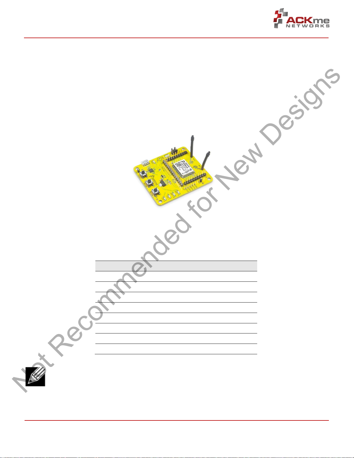
AMW006-E03 ‘Moray’
(with AMW006 surface mount module)
Not Recommended for New Designs
1 Introduction
The AMW006 ‘Numbat’ module is a fully certified small form factor, low power Wi-Fi networking module perfectly
suited to deeply embedded applications requiring medium/high data throughput in medium to high volume.
The module runs WiConnect firmware, ACKme Networks’ easy-to-use and reliable serial Wi-Fi networking application
that includes an embedded TCP/IP networking stack with SSL/TLS/HTTPS security.
Evaluation of WiConnect and the AMW006 module is available with the AMW006-E03 ‘Moray’ evaluation board. The
evaluation board is shown in Figure 1 and its features are shown in Table 1.
Figure 1. AMW006 Moray Evaluation Board
Table 1. AMW006 Evaluation Board Features
Note! Customers that wish to evaluate the AMW006 module using WICED should obtain an alternative
evaluation board that provides AMW006 program and debug capability. See the AMW006-E01 ‘Seabass’
WICED eval board.
ARG-MW006E-100R • AMW006 Evaluation Guide Page | 1 Page | 1
©2014 ACKme Networks. http://ack.me October 20, 2014 October 20, 2014
Page 4

AMW006 Evaluation Guide
AMW006
H6 AMW006
H8 AMW006
H8 AMW006
H7
GND
2 GND
12 UART0_TX
20 GND
27
VDD_DUT
3 GPIO 5
13 GPIO 13
21 GPIO 18
28
GPIO 0
4 GPIO 6
14 GPIO 14
22 GPIO 19
29
GPIO 1
5 GPIO 7
15 GPIO 15
23 GPIO 20
30
GPIO 2
6 GPIO 8
16 GPIO 16
24 GPIO 21
31
GPIO 3
7 UART0_RTS
17 GPIO 17
25 GPIO 22
32
GPIO 4
8 UART0_CTS
18 GND
26 GPIO 23
33
OSC_32K
9 UART0_RX
19
RESET_N
34
VDD_DUT
10
VDD_DUT
35
GND
11
GND
36
USB UART Tx LED
Expansion Header H7
USB UART Rx LED
User LED 1*
User Button 2*
User Button 1*
Reset Button
Used to reset the AMW006 module
Power LED
Thermistor
Expansion Header H6
USB Micro Connector
Provides power to the board &
Ground Hook
User LED 2*
AMW006 Module
System Indicator LEDs*
UART Header H4
Expansion Header H8
Antenna Connections
* User configurable
Not Recommended for New Designs
Feature Identification, Section 2
2 Feature Identification
2.1 AMW006-E03 ‘Moray’
The Moray evaluation board comes complete with a surface mount AMW006 ‘Numbat’ module. Each pin on the
Numbat module is connected to the expansion header. Schematics for the board are provided in Appendix B.
Figure 2. AMW006-E03 Features
USB-Serial UART to computer
Table 2. AMW006-E03 Expansion Header Connections
ARG-MW006E-100R • AMW006 Evaluation Guide Page | 2 Page | 2
©2014 ACKme Networks. http://ack.me October 20, 2014 October 20, 2014
Page 5
AMW006 Evaluation Guide
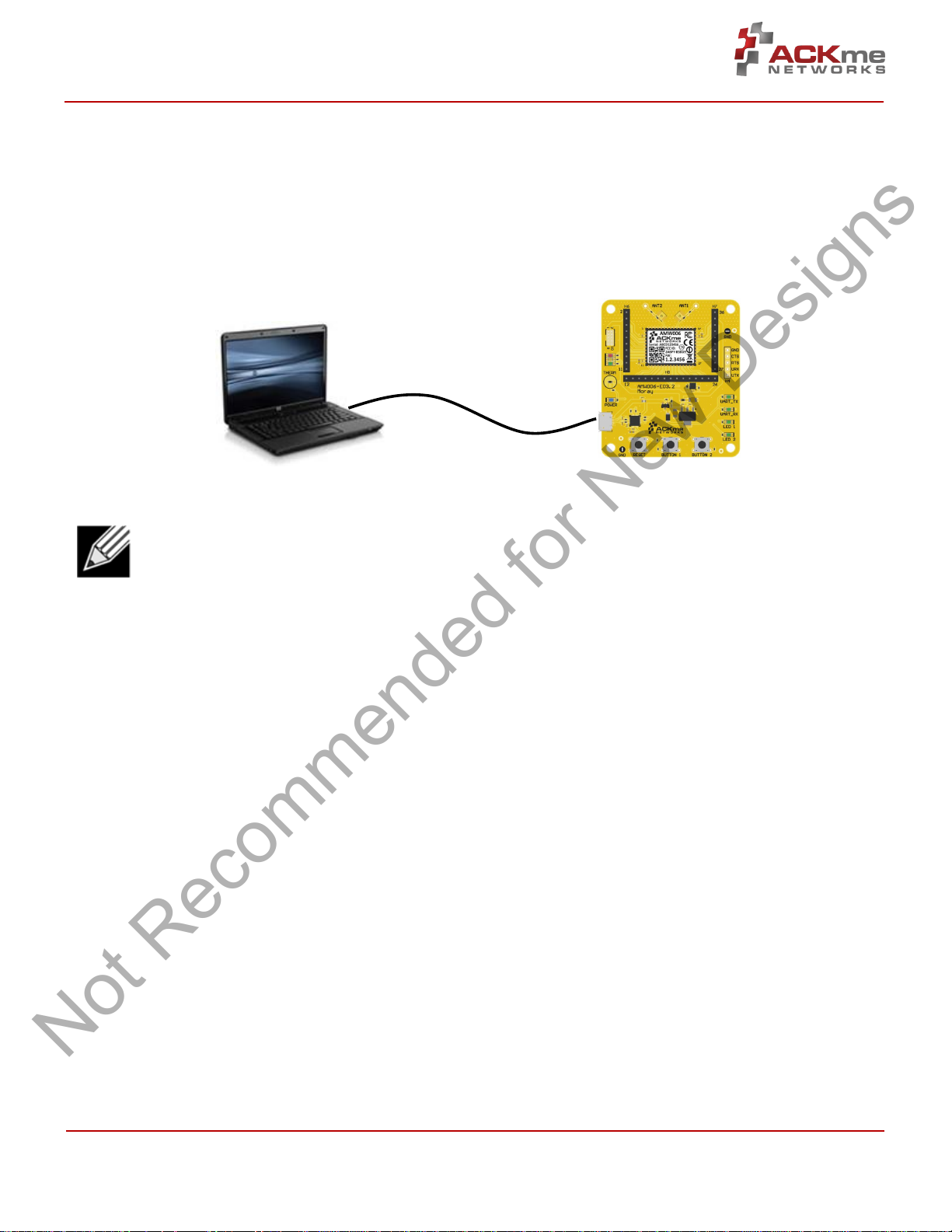
Computer with Terminal Emulator
Moray Evaluation Board
USB Serial
Not Recommended for New Designs
Using WiConnect, Section 3
3 Using WiConnect
To get started with WiConnect, plug the AMW006 evaluation board into the USB port of the computer and open a
terminal emulator as described in Appendix A. The USB cable provides the evaluation board with power and a serial
UART connection to the computer.
With the board connected to the computer, verify the power LED is illuminated. If the power LED is NOT illuminated,
try re-plugging the USB cable, or try a different USB cable.
Note! Be sure to use a quality USB cable. Inferior cables may result in reduced or intermittent operation
of the evaluation board.
3.1 Getting Help
WiConnect provides extensive help for each command and variable. To obtain a list of help options, type the help
command.
> help
The following help options are available ...
help all -> Print a list of all Commands and Variables
help commands -> Print a list of Commands
help variables -> Print a list of Variables
help <command> -> Print help for a specific Command
help <variable> -> Print help for a specific Variable
Additional help is available online at http://wiconnect.ack.me
To obtain help for a particular command or variable, type help <command> or help <variable>.
To obtain help for the wlan_scan variable, type help wlan_scan.
> help wlan_scan
Usage : wlan_scan [-v] [<channel> [ssid]]
Shortcut: scan
Brief : Initiate a Wi-Fi scan and return results; optionally specify
a channel and AP SSID to scan for. For verbose scans, -v must be the first argument
ARG-MW006E-100R • AMW006 Evaluation Guide Page | 3 Page | 3
©2014 ACKme Networks. http://ack.me October 20, 2014 October 20, 2014
Page 6
AMW006 Evaluation Guide
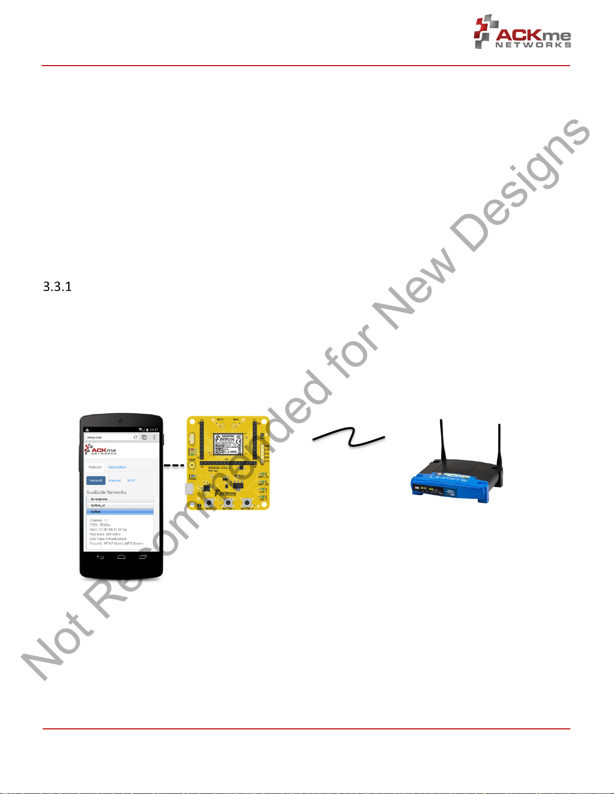
Remote Network
Name: YOUR_NETWORK_NAME
Local Network
Not Recommended for New Designs
Using WiConnect, Section 3
3.2 Scanning for Wi-Fi Networks
To scan for Wi-Fi networks in range, use the wlan_scan command. Each AP in range is listed on a separate line.
> wlan_scan -v
!3 networks found
! # Ch RSSI MAC BSSID Rate Security Mode Len Network (SSID)
# 0 06 -27 84:1B:5E:29:9D:F7 450.0 WPA2-Mixed Inf 17 YOUR_NETWORK_NAME
# 1 11 -73 2C:B0:5D:31:6F:6A 300.0 WPA2-AES Inf 6 button
# 2 11 -73 EC:1A:59:36:5B:6C 144.4 WPA2-Mixed Inf 5 ACKme
3.3 Joining a Wi-Fi Network
Several methods are available to configure and join the AMW006 module to a Wi-Fi network.
Web Setup
WiConnect provides the option to use a web browser running on a network client (such as a smartphone, tablet or
computer) to select the remote Wi-Fi network the AMW006 module should join, and to enter a password for the
remote network.
When web setup is used, it is helpful to think of the network client as the keyboard and display for the module as
shown in Figure 3.
Figure 3. Web setup using a network client
Name: WiConnect-######
Password: password
To start web setup mode, enter the command setup web. WiConnect starts the local network and web server as
indicated by the final message: In progress.
> setup web
[Disassociated]
IPv4 address: 10.10.10.1
Web setup started with the SSID: WiConnect-102F1A
In progress
ARG-MW006E-100R • AMW006 Evaluation Guide Page | 4 Page | 4
©2014 ACKme Networks. http://ack.me October 20, 2014 October 20, 2014
Page 7

AMW006 Evaluation Guide
Not Recommended for New Designs
Using WiConnect, Section 3
Open the Wi-Fi settings on your smartphone, tablet or computer and join the network called WiConnect-######
(where ###### are the last 6 digits of the Wi-Fi module MAC address). The password for the network is simply:
password. The local network name and password, and the web address may be customised to suit your needs, see
the online WiConnect Reference Manual for further information.
After joining the local network, open a web browser on the network client and go to setup.com. The WiConnect web
page appears (see Figure 3), and a scan begins for Wi-Fi access points in range. Select the remote network you wish
to join, enter the network password then select Save & Exit and follow the prompts.
Once the settings are successfully saved, WiConnect prints Web Setup Mode exited to the terminal. Check that
the settings were successfully saved using get wlan.ssid and get wlan.passkey.
Web Setup Mode exited
> get wlan.ssid
YOUR_NETWORK_NAME
> get wlan.passkey
YOUR_NETWORK_PASSWORD
Script Setup
If you prefer instead to enter configuration details for the Wi-Fi network, WiConnect provides a default setup script
to step you through the process. The setup script is provided as a file called default_setup.script on the
WiConnect file system. The setup script may be customised as required.
> setup cmd
> Enter Wi-Fi network name:
set wlan.ssid YOUR_NETWORK_NAME
Set OK
> Enter Wi-Fi network password:
set wlan.passkey YOUR_NETWORK_PASSWORD
Set OK
>
set wlan.auto_join.enabled true
Set OK
> Saving settings
save
Saved
Success
>
network_up
[2014-05-17 | 11:48:31: Associating to YOUR_NETWORK_NAME]
In progress
> Security type from probe: WPA2-Mixed
Obtaining IPv4 address via DHCP
IPv4 address: 192.168.0.31
[2014-05-17 | 11:48:41: Associated]
> Exiting Cmd Setup Mode
Manual Setup
It is straightforward to manually enter the name and password for the network using the wlan.ssid and
wlan.passkey variables too. Be sure to save afterwards, or the values will be lost when the module reboots. Any
subsequent command requiring network access, such as an ICMP (Internet Control Message Protocol) ping,
automatically results in the module attempting to join the network.
ARG-MW006E-100R • AMW006 Evaluation Guide Page | 5 Page | 5
©2014 ACKme Networks. http://ack.me October 20, 2014 October 20, 2014
Page 8

AMW006 Evaluation Guide
Not Recommended for New Designs
Using WiConnect, Section 3
> set wlan.ssid YOUR_NETWORK_NAME
Set OK
> set wlan.passkey YOUR_NETWORK_PASSWORD
Set OK
> save
Saved
Success
> ping -g
[Associating to YOUR_NETWORK_NAME]
Security type from probe: WPA2-Mixed
Obtaining IPv4 address via DHCP
IPv4 address: 192.168.0.31
[Associated]
Ping reply in 25ms
The network up –s command provides a shortcut to the process, by scanning for wireless Access Points, offering a
choice of networks to join and automatically saving the ssid and passkey:
> network_up -s
Scanning for networks...
! 3 networks found
! # Ch RSSI MAC (BSSID) Network (SSID)
# 0 1 -40 4C:55:CC:10:2E:50 ABC
# 1 1 -32 9C:D6:43:28:50:A0 myAP
# 2 6 -77 30:85:A9:E7:9C:B0 DEF
Type the number # that matches your Network: 1
Type the password for your Network : secretpassword
[Associating to myAP]
> In progress
> Security type from probe: WPA2-AES
Obtaining IPv4 address via DHCP
IPv4 address: 10.5.6.94
[Associated]
Wireless Protected Setup (WPS)
WPS is a Wi-Fi provisioning method originally intended to simplify the process of connecting Wi-Fi clients to Wi-Fi
Access Points. WPS offers both a push-button and PIN entry method for configuration. In reality, WPS push-button
(as opposed to PIN) is the only method that has gained some level of adoption in the industry, however WPS
naturally only works when the Wi-Fi AP supports WPS.
Many AP vendors choose not to test and certify APs with the Wi-Fi Alliance, and the lack of a standard WPS logo next
to the WPS button on an AP often means many users are unaware that WPS is available. The potential for equipment
incompatibility and added user confusion mean it is unwise to rely on WPS as the primary method of Wi-Fi
provisioning in the real world.
Incompatibility and confusion aside, WiConnect provides full support for WPS1.0 & WPS2.0 and the underlying WPS
engine has passed Wi-Fi certification. To use WPS in push-button mode, simply enter the wps command into
WiConnect, then press the WPS button on your router (if the router supports WPS, and it is enabled, and you can
find the button), and wait for the magic to happen.
ARG-MW006E-100R • AMW006 Evaluation Guide Page | 6 Page | 6
©2014 ACKme Networks. http://ack.me October 20, 2014 October 20, 2014
Page 9

AMW006 Evaluation Guide
Not Recommended for New Designs
Using WiConnect, Section 3
3.4 Filesystem
ACKme Wi-Fi modules running WiConnect include a serial flash memory and a filesystem that provides users with the
ability to read and write files. A quick example showing how to create, manipulate then delete a file is provided
below.
> file_create hello.txt 13
my hello data
File created
Success
> ls
! # Size Version Filename
# 0 1853 2.0.0 /favicon.ico.gz
# 1 18067 2.0.0 /setup/images.png
# 2 10525 2.0.0 /setup/index.css.gz
# 3 10143 2.0.0 /setup/index.html
# 4 39233 2.0.0 /setup/index.js.gz
# 5 32297 2.0.0 command_help.csv
# 6 135 2.0.0 default_setup.script
# 7 1236 2.0.0 geotrust_ca.pem
# 8 279 1.0.0 gpio_config_init.csv
# 9 13 1.0.0 hello.txt
# 10 212736 2.0.0 upgrade_app.exe
# 11 176920 2.0.0 wiconnect.exe
# 12 203261 5.26.230 wifi_fw.bin
> file_open hello.txt
[Opened: 0]
0
> stream_read 0 5
my he
> stream_read 0 50
llo data
[Closed: 0]
> file_delete hello.txt
File deleted
Success
Note! When reading the contents of a file using stream_read, the file is automatically closed if the end of
file is reached.
3.5 Saving Custom Configurations
All available WiConnect variables may be saved to a file as a custom configuration. Saved configuration may then be
loaded at a later date. This feature is particularly useful for saving configuration variables prior to an over-the-air
(OTA) upgrade, and then restoring the configuration afterwards.
> save my_config.csv
Success
> load my_config.csv
Configuration successfully loaded
ARG-MW006E-100R • AMW006 Evaluation Guide Page | 7 Page | 7
©2014 ACKme Networks. http://ack.me October 20, 2014 October 20, 2014
Page 10

AMW006 Evaluation Guide
Not Recommended for New Designs
Using WiConnect, Section 3
3.6 UDP / TCP / TLS Clients
To open a UDP, TCP or secure TLS connection to a remote server, use the udp_client, tcp_client or
tls_client commands. WiConnect responds with a stream handle if the connection is opened successfully. For TLS
connections, WiConnect provides a default TLS root certificate signed by GeoTrust (located on the WiConnect file
system), however this certificate may not work with some TLS servers. A custom certificate may be provided as an
option to the tls_client command if required.
> udp_client test.ack.me 50019
[Opening: test.ack.me:50019]
Resolving host: test.ack.me
Connecting: 107.170.222.80:50019
[2014-05-19 | 11:12:22: Opened: 0]
0
> tcp_client test.ack.me 50019
Resolving host: test.ack.me
[2014-05-19 | 11:12:38: Opening: test.ack.me:50019]
Connecting (TCP): 107.170.222.80:50019
[2014-05-19 | 11:12:39: Opened: 1]
1
> tls_client google.com 443
Resolving host: google.com
[2014-05-19 | 11:12:49: Opening: google.com:443]
Connecting (TLS): 74.125.237.174:443
[2014-05-19 | 11:12:50: Opened: 2]
2
Now try writing a character to the UDP or TCP stream that was opened in the examples above (remember,
WiConnect does NOT echo characters typed after the stream_write command). The server at http://test.ack.me
responds with a character pattern using the Chargen (Character Generator) protocol.
> stream_write 0 2
hi
Success
> stream_read 0 50
!"#$%&'()*+,-./0123456789:;<=>?@ABCDEFGHIJKLMNOPQR
Note! WiConnect supports TCP, UDP and TLS server modes too!
For more information, please refer to the WiConnect Reference Guide.
3.7 HTTP / HTTPS Clients
To open an HTTP or secure HTTPS connection to a remote server, read the first 300 bytes of the response then close
the connection, use the http_get, stream_read and stream_close commands. WiConnect responds with a
stream handle if the connection is opened successfully.
ARG-MW006E-100R • AMW006 Evaluation Guide Page | 8 Page | 8
©2014 ACKme Networks. http://ack.me October 20, 2014 October 20, 2014
Page 11

AMW006 Evaluation Guide
Not Recommended for New Designs
Using WiConnect, Section 3
> http_get https://www.google.com
[2014-05-19 | 11:14:31: Opening: https://www.google.com]
Request GET /
Connecting (HTTP): www.google.com:443
Starting TLS
[2014-05-19 | 11:14:31: Opened: 0]
HTTP response: 302
Redirected to https://www.google.com.au/?gfe_rd=cr&ei=l-d5U9m2J6GN8QfexoHYCg
Request GET /?gfe_rd=cr&ei=l-d5U9m2J6GN8QfexoHYCg
Connecting (HTTP): www.google.com.au:443
Starting TLS
HTTP response: 200
Status: 200
0
> stream_read 0 300
<!doctype html><html itemscope="" itemtype="http://schema.org/WebPage" lang="enAU"><head><meta content="/images/google_favicon_128.png"
itemprop="image"><title>Google</title><script>(function(){
window.google={kEI:"mOd5U4eZAYTVkAXF2oDwBA",getEI:function(a){for(var
b;a&&(!a.getAttribute||!(b=a.getAt
> stream_close 0
[2014-05-19 | 11:14:47: Closed: 0]
Success
>
3.8 Using GPIOs
In WiConnect, a GPIO may have two functions: a standard IO function or an alternate function (such as a system
indicator, status GPIO or control GPIO). When a GPIO is configured with an alternate function, the standard IO
function is NOT available and the gpio_dir, gpio_set, and gpio_get commands are disabled for that GPIO.
Before a GPIO can be used, it is necessary to first check whether the GPIO is being used for an alternate function, or
is already in use as a standard GPIO (for another purpose). If the GPIO is in use, it must first be freed up by setting
the direction of the GPIO to none using the gpio_dir command (standard IO) or by disabling the alternate function.
The example below demonstrates how to control GPIO 23 on the AMW006 module. GPIO 23 is unassigned after
factory reset.
> gpio_dir 23 out
Set OK
> get gpio.usage
! # Description
#13 - UART1 RX
#14 - UART1 TX
#17 - SPI CLK
#18 - SPI MOSI
#19 - SPI MISO
#21 - system.indicator.network
#22 - system.indicator.wlan
#23 - Standard I/O
> gpio_set 23 0
Set OK
> gpio_set 23 1
Set OK
> gpio_set 23 0
Set OK
ARG-MW006E-100R • AMW006 Evaluation Guide Page | 9 Page | 9
©2014 ACKme Networks. http://ack.me October 20, 2014 October 20, 2014
Page 12

AMW006 Evaluation Guide
Not Recommended for New Designs
Using WiConnect, Section 3
3.9 Factory Reset
The AMW006 module may be factory reset using the factory_reset command or by holding the factory reset pin
(GPIO 0 on all ACKme modules) high for more than 10 seconds through a hardware reset. After a successful factory
reset, all variables are set to factory defaults and the module reboots. To avoid accidental factory reset, the Wi-Fi
MAC address must be provided when calling the factory_reset command.
> get wlan.mac
4C:55:DC:15:02:5D
> factory_reset 4C:55:DC:15:02:5D
Reverting to factory default settings
Setting boot app to wiconnect.exe (0)
WiConnect-2.0.0.0, Built:2014-10-07 00:07:31 for AMW006.2, Board:AMW006-E03.1
[Ready]
>
3.10 Save & Reboot
When the value of a WiConnect variable is changed, the new value is only saved to RAM (not flash!). The value of
unsaved variables is lost when the module is reset or rebooted. To save variables to non-volatile flash memory, use
the save command. The following example demonstrates that failing to save the wlan.ssid prior to reboot results
in the newly assigned value being lost.
> get wlan.ssid
> set wlan.ssid ssid_WONT_be_saved
Set OK
> reboot
[Disassociated]
Rebooting
WiConnect-2.0.0.0, Built:2014-10-07 00:07:31 for AMW006.2, Board:AMW006-E03.1
[Ready]
> get wlan.ssid
> set wlan.ssid ssid_WILL_be_saved
Set OK
> save
Saved
Success
> reboot
[Disassociated]
Rebooting
WiConnect-2.0.0.0, Built:2014-10-07 00:07:31 for AMW006.2, Board:AMW006-E03.1
[Ready]
> get wlan.ssid
ssid_WILL_be_saved
>
Note! WiConnect configures some services (such as GPIO initialization) only after reboot. It may be
necessary to save and reboot the module before the new value of some variables takes effect.
3.11 Command vs. Stream Mode
The WiConnect serial interface may be used in either Command Mode or Stream Mode. A brief description of each of
these modes is provided in the following text. For detailed information, please refer to the WiConnect Reference
Guide.
ARG-MW006E-100R • AMW006 Evaluation Guide Page | 10 Page | 10
©2014 ACKme Networks. http://ack.me October 20, 2014 October 20, 2014
Page 13

AMW006 Evaluation Guide
Command
Description
set system.cmd.mode human
Enable human friendly command mode
set system.cmd.mode machine
Enable machine friendly command mode
Command
Human
/
Machine
Description
set system.print_level
all / 0
Set debug & informational print level
set system.cmd.header_enabled
0 / 1
Disable/enable a response header
set system.cmd.prompt_enabled
1 / 0
Turn on/off the user prompt
set system.cmd.echo
on / off
Turn on/off character echo. In human
mode, lets you see what you're typing
Not Recommended for New Designs
Using WiConnect, Section 3
Command Mode
Command mode provides an asynchronous command interface that a host may use to send and receive control and
data information. Command mode is typically used by a host to configure WiConnect, however it may also be used
by simple hosts that need ultimate master/slave control over information sent to, and received from, the module. All
preceding examples demonstrate usage of WiConnect in command mode.
There are two ways to interact with WiConnect in Command mode. When operating in human friendly command
mode, WiConnect provides verbose asynchronous responses that are easy for humans to read. In machine friendly
command mode, verbose prints and the command prompt are disabled and a well-defined response header is
returned after each command.
Configuring Command Mode
Command mode can be configured using the convenience variable system.cmd.mode
Setting system.cmd.mode executes a macro that sets the value of the four variables used to switch between
human and command mode. These variables, together with the human and machine mode setting, are listed in the
following table.
Stream Mode
Stream Mode provides a streaming interface that transparently connects a WiConnect serial interface with a network
stream such as a UDP, TCP or TLS client or server. Stream mode provides a simple 1-1 connection between a physical
serial interface and a network stream.
Bytes or characters sent from the host to a serial interface are transparently pushed by WiConnect to a network
stream via a wireless interface. Conversely, bytes or characters received by a network stream (from a remote server)
via a wireless interface are transparently pushed by WiConnect to a serial interface connected to the host. A wireless
serial port is a typical application that uses stream mode.
3.12 Want more?
The WiConnect Reference Guide, available online at http://wiconnect.ack.me, provides detailed information about
all WiConnect features, commands and variables, versions and release notes.
A number of simple and more sophisticated example applications are also provided to help you get the most out of
WiConnect and the AMW006 module.
ARG-MW006E-100R • AMW006 Evaluation Guide Page | 11 Page | 11
©2014 ACKme Networks. http://ack.me October 20, 2014 October 20, 2014
Page 14

AMW006 Evaluation Guide
Part Number
Picture
Description
AMW006-E03
‘Moray’
WiConnect development and evaluation platform for the surface-mount
AMW006 module. The surface mount AMW006 module is not
removable.
Not Recommended for New Designs
Ordering Information, Section 4
4 Ordering Information
Table 4 provides ordering information for AMW006 evaluation boards.
Table 3. Ordering Information
ARG-MW006E-100R • AMW006 Evaluation Guide Page | 12 Page | 12
©2014 ACKme Networks. http://ack.me October 20, 2014 October 20, 2014
Page 15

AMW006 Evaluation Guide
Revision
Date
Change Description
ARG-MW006E-100R
Oct 20, 2014
First release
Not Recommended for New Designs
Revision History & Glossary, Section 5
5 Revision History & Glossary
5.1 Revision History
Table 4: Document Revision History
5.2 Glossary
In most cases, acronyms and abbreviations are defined on first use. A comprehensive list of acronyms and other
terms used in ACKme Networks documents are provided on the ACKme Networks website at
http://ack.me/FAQs/Glossary.
ARG-MW006E-100R • AMW006 Evaluation Guide Page | 13 Page | 13
©2014 ACKme Networks. http://ack.me October 20, 2014 October 20, 2014
Page 16

AMW006 Evaluation Guide
Not Recommended for New Designs
Appendix A – Configuring a Terminal Emulator
APPENDIX A – Configuring a Terminal Application
The following instructions describe how to obtain and install a serial terminal application for use on computers
running a Windows® or OS X operations system. ACKme recommends using PuTTY for Windows® systems and
CoolTerm for OS X systems, however other equivalent applications may work equally well.
Plug the evaluation board into the computer using a USB cable before continuing.
Verify USB-Serial Driver Installation
The USB-Serial interface on WiConnect evaluation boards is based on an FTDI chip used widely in the industry. Most
operating systems including Windows®, OS X, and Linux provide integrated FTDI driver support as part of the
operating system. However on some older machines, or machines that do not pickup regular updates, the driver may
not automatically install and it is necessary to manually install the driver.
On computers running Windows®, check if the driver is installed as follows:
Display the System Control Panel (e.g. press the ‘Windows’ key + Pause key).
In the left-hand column near the top of the panel, click Device Manager
In the Device Manager dialog, expand the Ports (COM and LPT) branch
FTDI drivers appear under the USB Serial Port items. If no items of this kind appear, the drivers may
not be installed.
Note: The driver entry may not appear if the ACKme device is not connected to the USB port and
powered on.
Double click the USB Serial Port entry.
Select the General tab in the USB Serial Port Properties dialog. Check the following:
o Manufacturer: FTDI
o Device status: This device is working properly
Select the Driver tab in the USB Serial Port Properties dialog. Check the following:
o Driver Provider: FTDI
o Update drivers if necessary by clicking the Update Driver… button.
In some cases, the FTDI driver may actually be correctly installed, but the driver may not enumerate
as a Virtual Communications Port (VCP). If this is the case, find the device under the USB Serial Bus
controllers section of the Device manager, open the device, check the VCP box, then click OK. It may
be necessary to unplug/replug your evaluation board in order for the VCP driver to load correctly.
If the FTDI drivers do not appear to be installed, see the installation instructions on the FTDI official site:
http://www.ftdichip.com/Support/Documents/InstallGuides.htm
ARG-MW006E-100R • AMW006 Evaluation Guide Page | 14 Page | 14
©2014 ACKme Networks. http://ack.me October 20, 2014 October 20, 2014
Page 17

AMW006 Evaluation Guide
Not Recommended for New Designs
Appendix A – Configuring a Terminal Emulator
Set Up Tera Term for Windows®
Tera Term is available as a free download from http://ttssh2.sourceforge.jp. Download and install Tera Term now if
you have not already done so. The following procedure describes how to establish a UART serial connection between
Tera Term and the evaluation board.
1. Start the Tera Term application and click on the Setup tab. A
dropdown appears providing options to configure Tera Term as
shown in the screen capture on the right. Select Terminal.
2. Terminal Setup. In the New-line section of the Setup Terminal
dialog box (see the screen capture below), ensure that:
Receive: is set to CR
Transmit: is set to CR+LF
Close the Terminal Setup dialog box by selecting OK.
3. Serial Port Setup. Select the Setup tab again from the main window, then select Serial port. A Setup serial
port dialog box appears. Ensure the settings in the dialog box match the settings shown in the following
screen capture. The COM Port shown in the example (COM14) will almost certainly be different for your
evaluation board, be sure to choose the COM port that matches your board.
When the serial port has been correctly setup, close
the Serial port setup dialog box by selecting OK.
ARG-MW006E-100R • AMW006 Evaluation Guide Page | 15 Page | 15
©2014 ACKme Networks. http://ack.me October 20, 2014 October 20, 2014
Page 18

AMW006 Evaluation Guide
Not Recommended for New Designs
Appendix A – Configuring a Terminal Emulator
4. New Connection. From the Tera Term application menu,
setup a new connection with the evaluation board by
selecting File | New connection (or by pressing Alt + N) as
shown in the screen capture on the right. A New connection
dialog box appears as shown in the following screen capture.
Check the Serial radio button, then click the Port: dropdown
menu and select the COM port that matches your evaluation
board. The COM port description for the evaluation board
includes the text COMxx: USB Serial Port (COMxx).
Once the correct COM port has been selected, close the
New connection dialog box by selecting OK.
5. Testing the connection. If Tera Term was able to connect successfully, the text in the application title bar
indicates which COM port is connected, and the baud rate of the connection. For the example documented
above, Tera Term displays ‘COM14:115200baud’. The Tera Term screen remains blank however until a
character is sent to WiConnect. Try pressing the Enter key, WiConnect responds with Ready as shown in the
following screen capture.
ARG-MW006E-100R • AMW006 Evaluation Guide Page | 16 Page | 16
©2014 ACKme Networks. http://ack.me October 20, 2014 October 20, 2014
Page 19

AMW006 Evaluation Guide
Not Recommended for New Designs
Appendix A – Configuring a Terminal Emulator
Set Up CoolTerm for OS X
CoolTerm is available as a free download from http://freeware.the-meiers.org/CoolTermMac.zip. Download and
install CoolTerm now if you have not already done so.
The following procedure describes how to establish a UART serial interface between CoolTerm and the evaluation
board.
1. Start the CoolTerm application and click the
Options menu icon. The CoolTerm Configuration
window opens. Set the Serial Port configuration
options as follows:
Port: usbserial-XXXXXXXX
Baudrate: 115200
Data bits: 8
Parity: none
Stop bits: 1
Flow control : Deselect all options
2. Click OK.
3. Click the Connect menu icon. The CoolTerm
application connects to the evaluation board.
Try pressing the Enter key, if CoolTerm is successfully connected to the evaluation board, WiConnect responds with
Ready
>
ARG-MW006E-100R • AMW006 Evaluation Guide Page | 17 Page | 17
©2014 ACKme Networks. http://ack.me October 20, 2014 October 20, 2014
Page 20

1
1
2
2
3
3
4
4
5
5
6
6
7
7
8
8
D D
C C
B B
A A
Title:
Size: Rev.:
Rev. Date:
Sheet of
Drawn:Filename
Print Date:
PCB Rev.:
C Cop yright
ACKme Networks Pty Ltd
20/10/2014
Moray.SchDoc
Moray (AMW006-E03)
2
A3
1 1
Copy rig ht 201 4, ACKme Netw orks In c.
ht tp : // ack.m e
Chad O'Neill
20/10/2014
2014
Document Number:
90-001-0025-020
VDD_ DUT
USART1 _RTS
USART1_RX
USART1_TX
GPIO6
GPIO7
GPIO8
GPIO1 3
RESET_N
USART1 _CTS
OSC_3 2K
JTAG_TCK
JTAG_TDI
JTAG_TDO
JTAG_TMS
GPIO0
GPIO1 4
GPIO1 5
GPIO1 6
GPIO1 7
GPIO1 8
GPIO1 9
GPIO2 0
GPIO2 1
GPIO2 2
GPIO2 3
GND
121314151617181920212223242526
H8
GND
2
3
4
5
6
7
8
9
10
11
H6
36
35
34
33
32
31
30
29
28
27
H7
GNDGND
GNDGND
GPIO5
VDD_ DUT
VDD_ DUT
100 nFC16
100 nFC18
GND
GND
VDD_ DUT
USART1_ RTS
USART1_RX
USART1_TX
GPIO5
GPIO6
GPIO7
GPIO8
GPIO1 3
RESET_N
10u FC15
10u FC17
LED_2
BUTTON_1
BUTTON_2
USART1_ CTS
OSC_3 2K
JTAG_TCK
JTAG_TDI
JTAG_TDO
JTAG_TMS
100 nFC14
GPIO0
GPIO1 4
GPIO1 5
GPIO1 6
GPIO1 7
GPIO1 8
GPIO1 9
GPIO2 0
GPIO2 1
GPIO2 2
GPIO2 3
GND
ANT_1
DNF
C12
GND
GND
GND
DNFC13
GND
H1
TP1
ANT_2
GND
H2
TP2
LED_1
THERM
LED_G
LED_Y
LED_R
RESET_N
GND
47k
R11
VDD_ 3V3
220 RR1 2
220 RR1 3
GND
LED_2
LED_1
BUTTON_1
VDD_ 3V3
47k
R14
GND
BUTTON_ 2
VDD_ 3V3
47k
R15
GND
Green
D5
Green
D4
LED_1LED_2
FID1 FID2 FID3
M3M2 M4 M5
S2
S1
S3
TP9 TP10
GND GND
220 R
R18
220 R
R19
GND
GreenD8Yellow
D6
LED_G
LED_Y
220 R
R20
Red
D7
LED_R
USART1_ CTS
USART1_ TX
GND
USART1_ RTS
USART1_ RX
UART Heade r
1
2
3
4
5
H4
VDD
1
GND
2
JTAG_TCK5JTAG_TMS
6
JTAG_TDI3JTAG_TDO
4
RESET_N
8
AUX
7
UART_T X
10
UART_RX
9
ACKm e D ebu g H ead er - DNF
H3
VDD
1
GND
2
JTAG_TCK5JTAG_TMS
6
JTAG_TDI3JTAG_TDO
4
RESET_N
8
AUX
7
UART_T X
10
UART_RX
9
ACKm e Pr ogr am m in g H eade r
H5
JTAG_TMSJTAG_TCK
RESET_N
VDD_DUT
GND
JTAG_TDI JTAG_TDO
USART1_RX USART1_TX
BUTTON_ 2
JTAG_TMSJTAG_TCK
RESET_N
VDD_DUT
GND
JTAG_TDI JTAG_TDO
USART1_RX USART1_TX
BUTTON_ 2
Vin
3
ADJ
1
Vout
2
LM11 17 MP-3. 3
U1
Green
D2
100n F
C7
MH2
MH1
2
3
4
5
1
MH3
MH4
Micr o U SB B Soc ket
USB1
GND
GND
USB_DM
USB_DP
220 Oh m @ 1 00 MHz
L1
220 RR9
VDD_ 3V3
100 nF
C4
100 nF
C5
GND
Blue
D1
220 R
R2
VDD_ 3V3 VDD_ DUTVDD_ 5V
0R
R1
VCC
10
VCCIO
1
3V3OUT
8
GND3GND
13
USBDM
7
USBDP
6
RESET#
9
TXD
15
RXD
2
RTS#
16
CTS#
4
CBUS0
12
CBUS1
11
CBUS2
5
CBUS3
14
EP
17
FT230 XQ
U2
10n F
C8
GND
27R
R16
27RR17
47p F
C10
47 pF
C9
GND GND
3V3 _USB
3V3 _USB
3V3 _USB
100 nF
C11
GND
GND
4. 7uF
C6
GND G ND
S
D
G
Si23 33 DS ( P-Ch )Q1
100 k
R3
100 nF
C1
1k
R4
PWREN_L
PWREN_L
USART1 _RX_U SB
USART1 _TX_U SB
USART1 _RTS_U SB
Green
D3 220 RR10
5V_ USB
1kR5
1kR6
USART1_RX
USART1_TX
RX_LED
TX_LED
47u F
C2
47u F
C3
1kR8 USART1_ RTS
1kR7 USART1_ CTS
USART1 _CTS_U SB
" Rese t But t on" " Bu t ton 1" " Bu t ton 2"
GND
THERM
VDD_ 3V3
t°
10k
RT1
10k
R21
Press But to n 2 t o
wak e th e m od ule
from sle ep
To f act ory r ese t the m od ule:
- Press and h old Bu tt on 1
- Press and r elea se th e
Reset Bu tt on
- Wai t for 10 se con ds
- Releas e B utt on 1
" User LED's" " System I n d i cat o r LEDs"" Ther m istor "
DNF
C19
DNF
C20
GND
1
SDA
2
SCL
6
RST
7
VCC
8
2.0 C
U5
APPLE_AUTH
100 nF
C34
VDD_3V3
GNDGND
I2 C_SCL
I2 C_SD A
I2 C_SCL
I2 C_SD A
2k2
R25
2k 2
R23
VDD_ 3V3
0R
R24
0R
R27
0R
R26
0R
R22
SM40 05 PL-TP
D9
GND
2
VBAT
3
GPIO0 / SPI 1_M ISO(S ) / FACTORY_RESET
4
GPIO1
5
GPIO2 / SPI 1_ SCK ( S) / ADC
6
GPIO3 / SPI 1_CS ( S) / ADC
7
GPIO4 / AD C
8
CLK_3 2K_ OUT
9
VDD_ MCU
10
GND11GND
12
GPIO5 / SPI 1_M OSI ( S) / PWM
13
GPIO6 / SPI 0_M ISO ( M)
14
GPIO7 / SPI 0_S CK ( M)
15
GPIO8 / SPI 0_M OSI ( M)
16
GPIO9 / UART0 _RTS
17
GPIO1 0 / UART0_ CTS / PWM
18
GPIO1 1 / UART0 _RX / PWM
19
GPIO1 2 / UART0_ TX / PWM
20
GPIO1 3 / PWM
21
GPIO1 4 / PWM
22
GPIO1 5 / PWM
23
GPIO1 6 / PWM
24
GPIO1 7 / UART1_ RX / ADC / PWM
25
GND26GND
27
GPIO1 8
28
GPIO1 9 / UART1_ TX / ADC / PWM
29
GPIO2 0 / ADC / PWM
30
GPIO2 1 / ADC / PWM
31
GPIO2 2 / UART1_ CTS / ADC / WKUP / PWM
32
GPIO2 3 / UART1_ RTS / ADC / PWM
33
RESET_N
34
VDD_ WI FI
35
GND
49
GND36GND37GND38GND39GND40GND41GND
42
GND
50
GND44GND45GND46GND51GND
48
GND
1
ANTENNA_ 1
43
ANTENNA_ 2
47
GND
52
ACKm e - Nu mb at ( AMW 006.4 )M1
Not Recommended for New Designs
Appendix B – Evaluation Board Schematics & Mechanical Dimensions
The schematic on this page is for Moray version 2 - AMW006-E02.2. Schematics for other board revisions are available at http://ack.me/resources/show
ARG-MW006E-100R• AMW006 Evaluation Guide Page | 18
©2014 ACKme Networks. http://ack.me October 20, 2014
Page 21

Smart.
Not Recommended for New Designs
Connected.
Energy-Friendly.
Products
www.silabs.com/products
Disclaimer
Silicon Labs intends to provide customers with the latest, accurate, and in-depth documentation of all peripherals and modules available for system and software implementers using or
intending to use the Silicon Labs products. Characterization data, available modules and peripherals, memory sizes and memory addresses refer to each specific device, and "Typical"
parameters provided can and do vary in different applications. Application examples described herein are for illustrative purposes only. Silicon Labs reserves the right to make changes
without further notice and limitation to product information, specifications, and descriptions herein, and does not give warranties as to the accuracy or completeness of the included
information. Silicon Labs shall have no liability for the consequences of use of the information supplied herein. This document does not imply or express copyright licenses granted
hereunder to design or fabricate any integrated circuits. The products are not designed or authorized to be used within any Life Support System without the specific written consent of
Silicon Labs. A "Life Support System" is any product or system intended to support or sustain life and/or health, which, if it fails, can be reasonably expected to result in significant
personal injury or death. Silicon Labs products are not designed or authorized for military applications. Silicon Labs products shall under no circumstances be used in weapons of mass
destruction including (but not limited to) nuclear, biological or chemical weapons, or missiles capable of delivering such weapons.
Trademark Information
Silicon Laboratories Inc.® , Silicon Laboratories®, Silicon Labs®, SiLabs® and the Silicon Labs logo®, Bluegiga®, Bluegiga Logo®, Clockbuilder®, CMEMS®, DSPLL®, EFM®,
EFM32®, EFR, Ember®, Energy Micro, Energy Micro logo and combinations thereof, "the world’s most energy friendly microcontrollers", Ember®, EZLink®, EZRadio®, EZRadioPRO®,
Gecko®, ISOmodem®, Micrium, Precision32®, ProSLIC®, Simplicity Studio®, SiPHY®, Telegesis, the Telegesis Logo®, USBXpress®, Zentri, Z-Wave and others are trademarks or
registered trademarks of Silicon Labs. ARM, CORTEX, Cortex-M3 and THUMB are trademarks or registered trademarks of ARM Holdings. Keil is a registered trademark of ARM Limited.
All other products or brand names mentioned herein are trademarks of their respective holders.
Silicon Laboratories Inc.
400 West Cesar Chavez
Austin, TX 78701
USA
Quality
www.silabs.com/quality
Support and Community
community.silabs.com
http://www.silabs.com
 Loading...