


WRAP MULTIRADIO ACCESS SERVER
User’s and Developer’s Guide
Version 2.0.3
Monday, November 08, 2004

Bluegiga Proprietary, Copyright © Bluegiga Technologies 2001-2004
All rights reserved.
Bluegiga Technologies assumes no responsibility for any errors which may appear in this
manual. Furthermore, Bluegiga Technologies reserves the right to alter the hardware, software,
and/or specifications detailed herein at any time without notice, and does not make any
commitment to update the information contained herein. Bluegiga Technologies’ products are
not authorized for use as critical components in life support devices or systems.
The WRAP is a registered trademark of Bluegiga Technologies.
The Bluetooth trademark is owned by the Bluetooth SIG Inc., USA, and is licensed to Bluegiga
Technologies.
ARM and ARM9 are trademarks of ARM Ltd.
Linux is a trademark of Linus Torvalds.
All other trademarks listed herein belong to their respective owners.
2004-11-08

USER'S AND DEVELOPER'S GUIDE WRAP MULTIRADIO ACCESS SERVER
CONTENTS
1 Introduction ....................................................................................................... 6
1.1 Licenses and Warranty ......................................................................................6
1.2 Certification Information....................................................................................6
1.3 Bluegiga Technologies Contact Information ..........................................................9
2 Controlling the Access Server ........................................................................... 10
2.1 Physical Interfaces.......................................................................................... 10
2.2 Shell Prompt Access........................................................................................ 11
2.2.1 Management Console ............................................................................... 11
2.2.2 Accessing Remotely.................................................................................. 12
2.3 Transferring Files to/from the Access Server....................................................... 12
3 Configuration.................................................................................................... 14
3.1 Using the Setup Application..............................................................................14
3.1.1 Network Configuration .............................................................................. 14
3.1.2 Bluetooth Settings.................................................................................... 15
3.1.2.1 General Bluetooth Settings ................................................................. 15
3.1.2.2 LAN Access Profile Settings ................................................................. 16
3.1.2.3 Serial Port Profile Settings .................................................................. 16
3.1.2.4 OBEX Settings .................................................................................. 18
3.1.2.5 Personal Area Network Profile Settings ................................................. 19
3.1.3 Ramdisk Settings ..................................................................................... 19
3.1.4 System Logger Settings ............................................................................ 20
3.1.5 Web Server Settings................................................................................. 20
3.1.6 Install Point Settings ................................................................................ 20
3.1.7 SMS Gateway Settings.............................................................................. 20
3.2 /etc/rc.d/rc.local............................................................................................. 20
3.3 Resetting Configuration ................................................................................... 21
3.4 Advanced Configuration................................................................................... 21
4 Using the System.............................................................................................. 22
4.1 Bluetooth ......................................................................................................22
4.1.1 Bluetooth Server Socket Interface Password Protection .................................22
4.1.2 LAN Access Profile.................................................................................... 22
4.1.3 Serial Port Profile ..................................................................................... 22
4.1.4 Object Push and File Transfer Profile........................................................... 23
4.1.5 PAN Profile.............................................................................................. 24
4.1.6 Bluetooth Range Changing ........................................................................ 24
4.1.7 BTCLI - Bluetooth Server Command Line Interface Utility............................... 24
4.1.8 Serialbluetooth ........................................................................................ 24
4.2 Compact Flash GPRS Card................................................................................ 25
4.2.1 SIM Card’s PIN code................................................................................. 25
4.2.2 GPRS Troubleshooting ..............................................................................25
4.2.3 Console Message "serial_cs: ParseTuple: Bad CIS tuple"................................ 25
4.3 Compact Flash WLAN ...................................................................................... 26
4.3.1 Hostap Driver .......................................................................................... 26
4.3.2 Hermes Driver ......................................................................................... 26
4.3.3 General Configuration............................................................................... 27
4.4 Servers ......................................................................................................... 27
4.4.1 Web Server............................................................................................. 28
4.4.2 Install Point............................................................................................. 28
4.4.2.1 Install Point configuration ................................................................... 29
4.4.2.2 Install Point example configuration ......................................................29
4.4.3 SMS Gateway Server ................................................................................ 30
4.4.4 User Level Watchdog ................................................................................ 30
4.4.5 Remote Management................................................................................ 30
4.4.5.1 Overview.......................................................................................... 30
4.4.5.2 Management Packet Format................................................................ 31
4.4.5.3 Management Packet Information File Format ......................................... 32
4.4.5.4 Management System Environment Variables ......................................... 32

USER'S AND DEVELOPER'S GUIDE WRAP MULTIRADIO ACCESS SERVER
4.4.5.5
4.4.5.6 Management Reply Packet Destination Definition ................................... 33
4.4.5.7 Management With USB Memory Dongle ................................................ 34
4.4.6 FTP ........................................................................................................ 34
4.4.7 SSH ....................................................................................................... 34
4.4.8 Telnet .................................................................................................... 34
4.5 Utilities ......................................................................................................... 34
4.6 Real Time Clock.............................................................................................. 37
4.7 Time Zone ..................................................................................................... 38
4.8 System Re-Install and Upgrade ........................................................................ 38
5 Bluetooth Technology Overview ....................................................................... 39
5.1 Frequency Bands and Channel Arrangement ....................................................... 39
5.2 Power Considerations ...................................................................................... 40
5.3 Radio Frequency Propagation ...........................................................................40
6 Introduction to SDK.......................................................................................... 42
7 Installing the WRAP Software Development Environment ................................ 43
7.1 WRAP Software Development Environment System Requirements ......................... 43
7.2 Questions Asked by the Install Script................................................................. 43
8 Creating WRAP Applications ............................................................................. 45
8.1 Application Examples ......................................................................................45
8.1.1 Installing Examples .................................................................................. 45
8.1.2 Running Examples.................................................................................... 45
8.2 Creating a New Project .................................................................................... 47
8.3 Building From the Command Line...................................................................... 47
8.4 Transferring an Application to WRAP Hardware ...................................................48
8.4.1 Transferring an Application to WRAP Using (S)FTP or SCP .............................. 48
8.4.2 Transferring an Application to WRAP Using Terminal Software ........................49
8.4.3 Using NFS mount ..................................................................................... 49
8.5 Running an Application Transferred to WRAP ...................................................... 49
8.6 Using Debugger (GDB/DDD) ............................................................................ 49
9 Bluetooth Server Socket Interface.................................................................... 51
9.1 Terms ........................................................................................................... 51
9.2 Starting the Bluetooth Servers.......................................................................... 51
9.3 Basic Commands ............................................................................................ 51
9.3.1 Info .......................................................................................................53
9.3.2 Inquiry ................................................................................................... 54
9.3.3 Name ..................................................................................................... 55
9.3.4 Quit ....................................................................................................... 56
9.3.5 Set ........................................................................................................57
9.3.6 Ping ....................................................................................................... 63
9.3.7 Pong ...................................................................................................... 64
9.3.8 Shutdown ............................................................................................... 65
9.3.9 Sleep .....................................................................................................66
9.4 Connection Commands and Replies ................................................................... 67
9.4.1 Call........................................................................................................ 67
9.4.2 Connect.................................................................................................. 69
9.4.3 No Carrier............................................................................................... 70
9.4.4 Ring....................................................................................................... 71
9.4.5 Close...................................................................................................... 72
9.4.6 List ........................................................................................................ 73
9.4.7 Status .................................................................................................... 74
9.5 Service Discovery ........................................................................................... 75
9.5.1 SDP bdaddr UUID .................................................................................... 76
9.5.2 SdpSearch .............................................................................................. 77
9.5.3 SdpAttr .................................................................................................. 78
9.5.4 SdpQuery ...............................................................................................79
9.5.5 Sdp........................................................................................................ 80
9.6 Example Sessions ........................................................................................... 80
9.7 Error Codes ...................................................................................................81
Management Operation Example: IPQUERY ........................................... 32

USER'S AND DEVELOPER'S GUIDE WRAP MULTIRADIO ACCESS SERVER
9.8
WRAP Obex Libraries....................................................................................... 86
9.8.1 libobex ................................................................................................... 86
9.8.2 libobexclient............................................................................................ 87
9.8.3 Obexbrowser........................................................................................... 88
10 I/O API ............................................................................................................ 90
10.1 LED/BUZZER API .......................................................................................... 90
10.2 GPIO API ..................................................................................................... 90
11 About Bluegiga ................................................................................................. 91
Appendix A – WRAP Directory Structure................................................................... 93

USER'S AND DEVELOPER'S GUIDE WRAP MULTIRADIO ACCESS SERVER
1 INTRODUCTION
WRAP™
Bluegiga's WRAP product family offers for device manufacturers, teleoperators, integrators,
enterprises and platform developers a simple and fast way to set-up wireless communication
systems between standard or proprietary mobile devices, networks, machines and
instruments.
WRAP™ Multiradio Access Server
WRAP™ Multiradio Access Server is a cutting edge wireless Bluetooth basestation supporting
WLAN, Ethernet and GSM/GPRS offering TCP/IP connectivity. It can be deployed into existing
wired or wireless networks without uncompromising the speed, security and ease of
installation and management. WRAP Multiradio Access Server is an open platform for creating
and hosting also local applications and content in the Access Server. Bluegiga also provides
several additional software packages for different purposes; embedded device's Bluetooth
networking, mobile phone TCP/IP connectivity and generic application installation for different
mobile handsets.
It has support for multiple Bluetooth radios (model 2291 has one and model 2293 has three
installed) with configurable range up to 100 meters (class 1), USB host and Compact Flash.
The WRAP Multiradio Access Server enables you to connect a variety of equipment directly to
networks. As a software platform, WRAP Multiradio Access Server runs Linux 2.4 in powerful
ARM processor and has free memory for runtime and persistent storage use of the user
applications.
1.1 L
ICENSES AND WARRANTY
Warning: Bluegiga Technologies is hereby willing to license the enclosed WRAP product and its
documentation under the condition that the terms and conditions described in the License
Agreement are understood and accepted. The License Agreement is supplied within every
WRAP product both in hard copy and soft copy (file \doc\WRAP_eula.pdf on the WRAP CDROM). The use of the WRAP product will indicate your assent to the terms. If you do not agree
to these terms, Bluegiga Technologies will not license the software and documentation to you,
in which event you should return this complete package with all original materials, equipment,
and media.
The following software components: GCC compiler tool chain, Linux kernel, and Linux-userland
applications are licensed under the terms and conditions of the GPL General Public License (file
\doc\GPL.txt on the WRAP CD-ROM). Upon request, Bluegiga will distribute a complete
machine-readable copy of the source of the aforementioned software components during a
period of three (3) years from the order date of the product. Delivery costs of the source code
will be charged from the party requesting the source code.
The Bluegiga WRAP Product Limited Warranty Statement is located in the file
\doc\WRAP_warranty.pdf on the WRAP CD-ROM.
1.2 C
ERTIFICATION INFORMATION
The product is CE approved and Bluetooth qualified v.1.1. It has been measured against the
following specification standards: Radio spectrum Matters (R&TTE, Article 3.2) ETSI EN 300
328-2 v1.3.1. / EN 301 489-1/17, and FCC part 15.247. Supported Bluetooth profiles are:
GAP, SDAP, LAN client and server, SPP A and B, FTP client and server, ObjP client and server,
PAN-PANU, PAN-GN and PAN-NAP.
Bluegiga Proprietary, Copyright © Bluegiga Technologies 2001-2004 6 (94)

USER'S AND DEVELOPER'S GUIDE WRAP MULTIRADIO ACCESS SERVER
Hereby, Bluegiga Technologies declares that this WRAP Multiradio Access Server is in
compliance with the essential requirements and other relevant provisions of Directive
1999/5/EC.
This device complies with Part 15 of the FCC Rules.
Operation is subject to the following two conditions:
1. This device may not cause harmful interference, and
2. This device must accept any interference received, including interference that may
cause undesired operation.
This equipment has been tested and found to comply with the limits for a Class B digital
device, pursuant to Part 15 of the FCC Rules. These limits are designed to provide reasonable
protection against harmful interference in a residential installation. This equipment generates,
uses, and can radiate radio frequency energy and, if not installed and used in accordance with
the instructions, may cause harmful interference to radio communications. However, there is
no guarantee that interference will not occur in a particular installation. If this equipment does
cause harmful interference to radio or television reception, which can be determined by turning
the equipment off and on, the user is encouraged to try to correct the interference by 1 or
more of the following measures:
• Reorient or relocate the receiving antenna
• Increase the separation between the equipment and receiver
• Connect the equipment into an outlet on a circuit different from that to which the
receiver is connected
• Consult the dealer or an experienced radio or television technician for help
Warning: Changes or modifications made to this equipment not expressly approved by
Bluegiga Technologies Inc. may void the FCC authorization to operate this equipment.
The radiated output power of the WRAP Multiradio Access Server is far below the FCC radio
frequency exposure limits. Nevertheless, the WRAP Multiradio Access Server should be used in
such a manner that the potential for human contact during normal operation is minimized.
To meet the FCC’s exposure rules and regulations:
• The antenna(s) used for this transmitter must be installed to provide a separation
distance of at least 20 cm from all the persons.
• Any transmitter installed in the CF card slot must not exceed 4 W of e.i.r.p. To check if
a particular equipment complies with this restriction you need to know its FCC ID
number and visit the searching engine in FCC web site in the following Internet address,
where you can find the output power by the equipment in the grant of the equipment
https://gullfoss2.fcc.gov/prod/oet/cf/eas/reports/GenericSearch.cfm
If this link does not work properly please visit FCC website (http://www.fcc.gov
follow the following steeps to find the searching engine:
FCC website Æ Office of Engineering Technology Æ Equipment Authorization Electronic
Filing Æ Generic Search
Please notice that the output power listed in the grant uses different units depending on
the type of the equipment, e.g.:
Bluegiga Proprietary, Copyright © Bluegiga Technologies 2001-2004 7 (94)
) and

USER'S AND DEVELOPER'S GUIDE WRAP MULTIRADIO ACCESS SERVER
1. The output power for 802.11a/b/g/h equipment or similar equipment approved
under §15.247 or §15.407 is listed as Conducted RF power. §15.247 or §15.407
limit the e.i.r.p. to 4 W, so this restriction is fulfilled.
2. The output power for Part 22 cellular equipment is listed as e.r.p. The
relationship between e.r.p. and e.i.r.p. is the following one:
e.i.r.p. = 1.64 x e.r.p.
3. The output power for Part 24 PCS equipment is listed as e.i.r.p.
4. For other type of equipment please consult the distributor in order to assure the
restriction is fulfilled.
Note: Definitions:
Effective Radiated Power (e.r.p.) (in a given direction): The product of the power supplied to
the antenna and its gain relative to half-wave dipole in a given direction.
Equivalent Isotropically Radiated Power (e.i.r.p.) (in a given direction): The product of the
power supplied to the antenna and its gain relative to an isotropic antenna.
The table below is excerpted from Table 1B of 47 CFR 1.1310 titled Limits for Maximum
Permissible Exposure (MPE), Limits for General Population/Uncontrolled Exposure:
Frequency Range (MHz) Power Density (mW/cm2)
300 – 1500 f/1500
1500 – 100 000 1.0
The equipment WRAP Multiradio Access Server transmits in the 2400 - 2483.5 MHz frequency
range, so the applicable MPE limit is 1 mW/cm
2
. The equipment can be provided with up to 4
Bluetooth modules WRAP THOR 2022-1-B2B (FCC ID: QOQWRAP2022-1-B2B):
Under the conditions stated above MPE limits can be guaranteed as the calculation below
shows:
Example 1:
15.247 or 15.407 Compact Flash Card with maximum allowed e.i.r.p. of 4W
Using equation from page 18 of OET Bulletin 65, Edition 97-01:
2
S = P·G/4πR
= Prad (e.i.r.p.)/4πR2
Where,
2
S = power density in mW/cm
(1 mW/cm2 used for G)
P = power input to the antenna
G = power gain of the antenna in the direction of interest relative to an isotropic radiator
R = distance to the centre of radiation of the antenna in cm (20cm Prediction distance)
S
Compact Flash card
= Prad (e.i.r.p.)
Compact Flash card
/4πR2 = 4000mW/4π(20cm)2
we obtain the following results:
S
Compact Flash card
= 4 x S
S
Total
= 0.795774mW/cm2
+ S
module
Compact Flash card
= 4 x 0.003579mW/cm2 + 0.795774mW/cm2
Bluegiga Proprietary, Copyright © Bluegiga Technologies 2001-2004 8 (94)

USER'S AND DEVELOPER'S GUIDE WRAP MULTIRADIO ACCESS SERVER
= 0.014316mW/cm2 + 0.795774mW/cm2 = 0.795774mW/cm2 < 1mW/cm2
S
Total
Example 2:
Part 22 Compact Flash Card with maximum e.r.p. of 1.5 W (Category excluded of MPE
evaluation according to §2.1091)
Using equation from page 18 of OET Bulletin 65, Edition 97-01 and considering that e.i.r.p. =
1.64 x e.r.p.:
S
Compact Flash card
S
Compact Flash card
= 4 x S
S
Total
= 0.014316mW/cm2 + 0.489401mW/cm2 = 0.503717mW/cm2 < 1 mW/cm2
S
Total
= Prad (e.i.r.p.)
Compact Flash card
= 0.489401mW/cm2
+ S
module
Compact Flash card
= 4 x 0.003579mW/cm2 + 0.489401mW/cm2
/4πR2 = 1500 x 1.64mW / 4π(20cm)2
Example 3:
Part 24 Compact Flash Card with maximum e.r.p. of 3 W (Category excluded of MPE
evaluation according to §2.1091)
Using equation from page 18 of OET Bulletin 65, Edition 97-01 and considering that e.i.r.p. =
1.64 x e.r.p.:
S
Compact Flash card
S
Compact Flash card
= 4 x S
S
Total
= 0.014316mW/cm2 + 0.978803mW/cm2 = 0.993119mW/cm2 < 1mW/cm2
S
Total
1.3 B
LUEGIGA TECHNOLOGIES CONTACT INFORMATION
= Prad (e.i.r.p.)
Compact Flash card
= 0.978803 mW/cm2
+ S
module
Compact Flash card
= 4 x 0.003579mW/cm2 + 0.978803 mW/cm2
/4πR2 = 3000 x 1.64mW / 4π(20cm)2
Please see http://www.bluegiga.com/
contact sales@bluegiga.com
.
Please check http://www.bluegiga.com/techforum/
Please contact support@bluegiga.com
for news and latest product offers. For more information,
for software and documentation updates.
if you need more technical support. To speed up the
processing of your support request, please include as detailed information on your product and
your problem situation as possible. Please begin your email with the following details:
• WRAP product type
• WRAP product serial number
• WRAP software version
• End customer name
• Date of purchase
Bluegiga Proprietary, Copyright © Bluegiga Technologies 2001-2004 9 (94)
USER'S AND DEVELOPER'S GUIDE WRAP MULTIRADIO ACCESS SERVER
2 CONTROLLING THE ACCESS SERVER
There is no graphical user interface for the WRAP Multiradio Access Server. All controlling
operations to the Access Server must be done either by entering commands and using
applications at Access Server shell prompt or by sending and/or retrieving files to/from the
Access Server. There are several ways to access the shell prompt and to transfer files.
2.1 P
HYSICAL INTERFACES
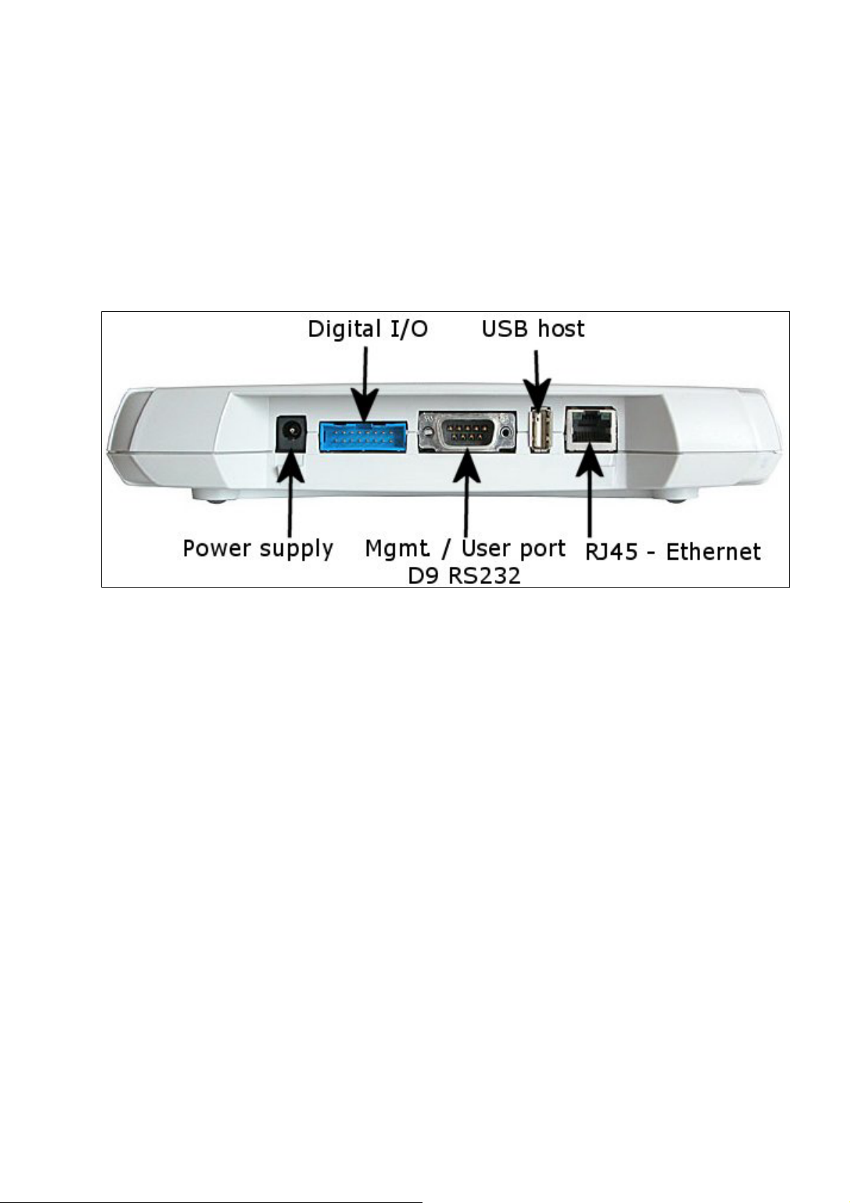
The physical interfaces of the Access Server are described in Figure 1 and Figure 2.
Figure 1. WRAP Multiradio Access Server Connectors.
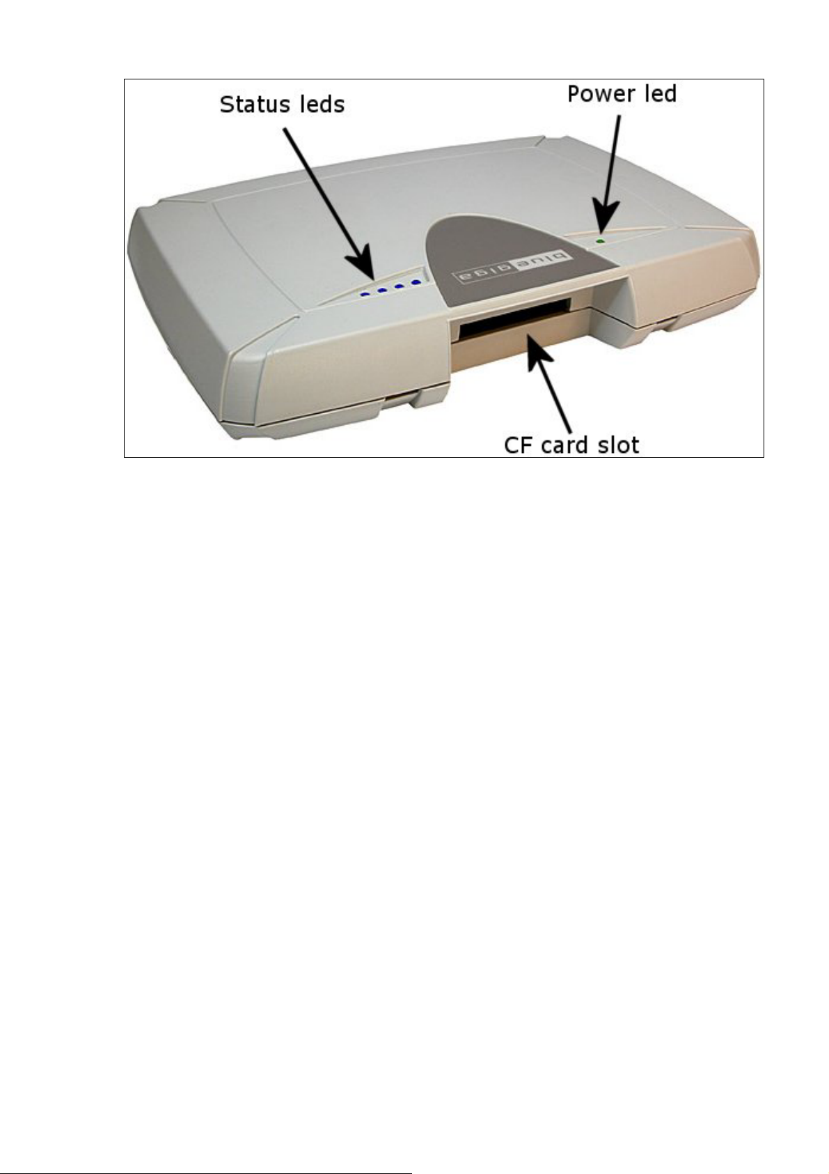
NOTE: The power adapter is the disconnection device, the socket-outlet shall be installed near
the equipment and shall be easy accessible. The power led (see Figure 2) is on when the
power adapter is connected.
Bluegiga Proprietary, Copyright © Bluegiga Technologies 2001-2004 10 (94)
USER'S AND DEVELOPER'S GUIDE WRAP MULTIRADIO ACCESS SERVER
Figure 2. WRAP Multiradio Access Server LEDs.
2.2 S
HELL PROMPT ACCESS
You can get to the shell prompt using either the management console, SSH or telnet. Normally
the initial configuration, if needed, is done from the management console over the serial cable
and all further controlling activities are performed remotely using SSH or telnet sessions over
Ethernet or Bluetooth LAN / PAN connection.
If you can make SSH or telnet connections from a device that has Bluetooth LAN Access or
PAN profile support, you don’t need the management console. Just connect the Access using
LAN Access or PAN profile. The Access Server can be seen in Bluetooth inquiries as
"Wserialno_n", where "serialno" is the serial number of the device and "n" is the number of the
Bluetooth radio in guestion (model 2293 has three Bluetooth radios, any of which can be
connected). After you have connected (no PIN code / username / password needed), connect
using SSH or telnet to the device in the other end of the connection, typically 192.168.160.1.
When logging in for the first time, log in as the user "root", and enter anything for password.
2.2.1 M
ANAGEMENT CONSOLE
If you don't have Bluetooth LAN/PAN client and you don't have the Access Server connected to
your LAN or you don't know the IP address given to the Access Server, you can get the first
shell prompt access using the management console. To set up management console do the
following:
1. Have a PC with a free COM port.
2. Power off the Access Server.
3. Configure your terminal application, like HyperTerminal in Windows, to use the
following settings with the free COM port:
Bluegiga Proprietary, Copyright © Bluegiga Technologies 2001-2004 11 (94)

USER'S AND DEVELOPER'S GUIDE WRAP MULTIRADIO ACCESS SERVER
Setting Value
Speed 115 200 bps
Data Bits 8
Parity None
Stop Bits 1
Flow Control None
Table 1. The Management Console Port Settings.
4. Connect the serial cable shipped with the Access Server to your PC's free COM port.
5. Connect the null-modem adapter shipped with the Access Server to the serial cable.
6. Connect the serial cable with the null-modem adapter to the management / user port in
the Access Server (see Figure 1).
7. Power on the Access Server.
8. Enter letter "b" in the terminal application during the first five seconds, while the blue
LEDs in the Access Server turn on one by one.
9. The management console is now activated and you should see the boot log in your
terminal window. Wait for the device to boot up and end with the prompt "[root@wrap
/]$ "
10. You are ready to control the Access Server from the management console.
2.2.2 A
When the WRAP is connected to a LAN it tries to get the IP address using DHCP by default.
One way to see the IP address of the WRAP board, connect to the WRAP with a management
console, power on the board and, after the system is up and running, give the command
"ifconfig nap". The field "inet addr" for the interface "nap" contains the IP address of the WRAP
board. For example, in the following capture from the management console, the IP address is
"10.1.1.43":
CCESSING REMOTELY
[root@wrap /]$ ifconfig nap
nap Link encap:Ethernet HWaddr 00:07:80:00:04:6C
inet addr:10.1.1.43 Bcast:10.255.255.255 Mask:255.255.255.0
inet6 addr: fe80::207:80ff:fe00:46c/64 Scope:Link
UP BROADCAST MULTICAST MTU:1500 Metric:1
RX packets:12635 errors:0 dropped:0 overruns:0 frame:0
TX packets:8 errors:0 dropped:0 overruns:0 carrier:0
collisions:0 txqueuelen:100
RX bytes:1686246 (1.6 MiB) TX bytes:1640 (1.6 KiB)
Interrupt:24 Base address:0xc000
You can use this address to connect the Access Server remotely via SSH, telnet, FTP, SFTP.
2.3 T
You can transfer file to and from the access server by default using for example:
Bluegiga Proprietary, Copyright © Bluegiga Technologies 2001-2004 12 (94)
RANSFERRING FILES TO/FROM THE ACCESS SERVER

USER'S AND DEVELOPER'S GUIDE WRAP MULTIRADIO ACCESS SERVER
- SCP (secure copy over SSH)
- SFTP (secure ftp connection over SSH)
- FTP (plain ftp connection), remember integrated client of the Internet Explorer
(type ftp://root:passwd@wrap-ip-address/
- Bluetooth OBEX (Object Push and File Transfer Profiles) to/from directory
"/tmp/obex" in WRAP Access Server
- NFS (mount a nfs-share from a remote device as a part of the file system of the
Access Server)
- USB memory dongle (mount it as a part of the file system of the Access Server)
- Xmodem/Ymodem/Zmodem (use "rz/rx/rb/sz/sx/sb" commands from the
management console)
in address bar)
Bluegiga Proprietary, Copyright © Bluegiga Technologies 2001-2004 13 (94)

USER'S AND DEVELOPER'S GUIDE WRAP MULTIRADIO ACCESS SERVER
3 CONFIGURATION
When the WRAP is installed and powered up for the first time, the default configuration
settings are being used. With these settings, the WRAP automatically configures its network
settings assuming that the board is connected to a LAN network with a DHCP server running.
After booting, you can use the WRAP as a Bluetooth LAN/PAN access point to the network
without any changes in configuration. Also, the Serial Port Profile is enabled by default in
listening mode. You can also use Object Push and File Transfer Profiles to send files to/from
the WRAP.
3.1 U
The basic configuration settings can be changed using the "setup" application. It displays the
settings in a hierarchical menu. Navigating the menu is accomplished by entering the number
or letter corresponding to the setting to be viewed and/or changed and pressing <enter>.
Pressing only <enter> either accepts the previous value of the setting or returns to the
previous level in the menu hierarchy. The settings and their meanings, as well as their default
values are described in the following sections.
Note: Ensure that your terminal application transmits only Carriage Return (CR) when the
<enter> key is pressed. If your terminal transmits both CR and LF, you cannot navigate in the
"setup" application.
3.1.1 N
SING THE SETUP APPLICATION
ETWORK CONFIGURATION
1. Enable Interface Eth0 [Y]
This option determines whether or not an Ethernet interface is brought up at all at boot.
If set to no, the other options in the Network Configuration menu are not visible.
2. Hostname of the Device [wrap]
The hostname of the WRAP device. Local applications will see this name.
Domain of the Device [locadomain]
3.
The domain name of the WRAP device. Local applications will see this name.
4. Time Server []
Hostname (or IP address) of the time server connected at system boot to retrieve
correct time using the Time Protocol (RFC 868)
5. Use Dynamic Network Configuration [Y]
This option determines whether or not automatic configuration of the Ethernet interface
using DHCP should be attempted at boot. If set to yes, the following options in the
Network Configuration menu are not visible.
6. IP Address of the Host [10.0.0.101]
If the dynamic network configuration is disabled (step 5), the IP address of the WRAP
must be entered here.
7. Subnet Mask [255.255.255.0]
Bluegiga Proprietary, Copyright © Bluegiga Technologies 2001-2004 14 (94)

USER'S AND DEVELOPER'S GUIDE WRAP MULTIRADIO ACCESS SERVER
If the dynamic network configuration is disabled (step 5), the network mask of the
WRAP must be entered here.
8. IP Address of the Default Gateway [10.0.0.254]
If the dynamic network configuration is disabled (step 5), the IP address of the default
gateway in the LAN to which the WRAP is connected must be entered here.
9. IP Address of the Primary Name Server [10.0.0.1]
The IP address of the primary name server.
10. IP Address of the Secondary Name Server [10.0.0.2]
The IP address of the secondary name server.
3.1.2 B
The Bluetooth settings are divided into general and profile specific settings, and are described
in the following sections.
3.1.2.1 G
LUETOOTH SETTINGS
ENERAL BLUETOOTH SETTINGS
1. Friendly Name [W$S_$p]
The name shown when this device is found when inquired about by other Bluetooth
devices. The name may end with asterisk (*), which will be replaced with the last 3
digits of the serial number of the WRAP board.
2. Bluetooth Server Socket Interface Password []
The password required to be entered before any commands when discussing with the
WRAP Bluetooth Server Socket Interface. Can be empty.
3. Connectable and Discoverable Mode [3]
The setting specifying whether this device is connectable and/or discoverable or not by
other Bluetooth devices.
When a device is connectable, other Bluetooth devices can make a Bluetooth connection
to it. Before making a connection, the calling device must know the Bluetooth address
of the device it is connecting to. The Bluetooth addresses can be found by making an
inquiry. When a device is discoverable, it shows up in inquiries. Possible values for all
combinations of these settings are:
0. Not connectable, not discoverable
1. Not connectable, discoverable
2. Connectable, not discoverable
3. Connectable and discoverable (default)
4. Master/Slave Role Switch Policy [1]
Bluegiga Proprietary, Copyright © Bluegiga Technologies 2001-2004 15 (94)

USER'S AND DEVELOPER'S GUIDE WRAP MULTIRADIO ACCESS SERVER
The setting specifying how the connecting Bluetooth devices should decide their roles.
When a device is calling another Bluetooth device, it originally is the master and the
answering device is the slave. When the connection is being built, a role switch can be
made. Normally, access point devices want to be the master for all their slaves, and
therefore they require a master-slave switch when a new device is connecting. This is
also how the WRAP is configured by default. Other possible combinations are:
0. Allow switch when calling, do not request when answering
1. Allow switch when calling, request when answering (default)
2. Do not allow switch when calling, request when answering
If you have problems with connecting to the WRAP, it might be due to the fact that your
client device does not support a master/slave switch. In this case, set this setting to
"0".
5. Default PIN Code []
The PIN code used when establishing connections. Up to 16 characters are significant.
If there is no default PIN code, the WRAP does not require a PIN code when
establishing connections. If in this case the other device requests a PIN code, the
default PIN code "1234" is sent, following the Bluetooth specification.
6. Power Save Mode and Parameters [4]
The power save mode used by default for all connections.
0. Active
1. Park: Round-robin
2. Park: Idle
3. Sniff: All
4. Sniff: Idle
3.1.2.2 LAN ACCESS PROFILE SETTINGS
1. Enable Lan Access Profile [Y]
Whether or not the LAN Access Profile is enabled.
2. Lan Access Login Name and Password []
The login name and password required from LAN Access Clients. Must be entered as a
single string, separated with a space. For example: "guest buffy". If empty (default), no
login is required.
3. Service Name (shown in SDP) [Lan Access Using PPP]
The name of this service as shown in the Service Discovery.
3.1.2.3 S
Note: The visibility of some of these settings is controlled by the "Act as the Calling Device"
setting.
Bluegiga Proprietary, Copyright © Bluegiga Technologies 2001-2004 16 (94)
ERIAL PORT PROFILE SETTINGS

USER'S AND DEVELOPER'S GUIDE WRAP MULTIRADIO ACCESS SERVER
Note2: the Serial Port Profile is disabled if the SMS Gateway is enabled, as they share the
same physical serial port.
1. Enable Serial Port Profile [Y]
Whether the Serial Port Profile is enabled or not.
2. Act as the Calling Device [N]
Whether this device should act as the calling device (DevA) or the answering device
(DevB).
3. BPS Rate [9600]
The bits-per-second rate of the connection. Possible values are 300, 1200, 2400, 4800,
9600, 19200, 38400, 57600, 115200, 230400, and 460800.
4. Data Bits [8]
The number of data bits in the connection. Possible values are 5, 6, 7, and 8.
5. Parity [0]
The parity bit setting of the connection. Possible values are: 0: no parity, 1: odd parity,
and 2: even parity.
6. Stop Bits [1]
The number of stop bits in the connection. Possible values are 1 and 2.
7. Hardware Flow Control (RTS/CTS) [Y]
Whether or not the hardware flow control is used in the connection.
8. Software Flow Control (XON/XOFF) [N]
Whether or not the software flow control is used in the connection.
9. Service Name (shown in SDP) [Serial Port]
The name of this service as shown in the Service Discovery. (This setting is visible only
when setting 2., "Act as the Calling device", is disabled.)
10. Bluetooth Address of the Remote Device [00:07:80:80:01:1f]
The Bluetooth address of the device to be contacted. (This setting is visible only when
setting 2., "Act as the Calling device", is enabled.)
11. Server Channel of the Remote Device [2]
The Bluetooth server channel of the device to be contacted. (This setting is visible only
when setting 2., "Act as the Calling device", is enabled.)
12. Optional Command Line Parameters for SPP Application []
Optional extra parameters for the WRAP Serial Port Profile application. Currently the
only supported parameter is "--msc", which enables transmitting of DCD/DSR status in
MSC. By default, they are not transmitted.
Bluegiga Proprietary, Copyright © Bluegiga Technologies 2001-2004 17 (94)

USER'S AND DEVELOPER'S GUIDE WRAP MULTIRADIO ACCESS SERVER
3.1.2.4 OBEX S
ETTINGS
1. Enable Object Push Profile [Y]
Whether or not the Object Push Profile is enabled.
2. Service Name (shown in SDP) [OBEX Object Push]
The name of this service as shown in the Service Discovery.
3. Enable File Transfer Profile [Y]
Whether or not the File Transfer Profile is enabled.
4. Service Name (shown in SDP) [OBEX File Transfer]
The name of this service as shown in the Service Discovery.
Bluegiga Proprietary, Copyright © Bluegiga Technologies 2001-2004 18 (94)

USER'S AND DEVELOPER'S GUIDE WRAP MULTIRADIO ACCESS SERVER
3.1.2.5 P
ERSONAL AREA NETWORK PROFILE SETTINGS
1. Personal Area Network User (PANU) Profile
1. Enable PANU
Whether or not the PAN User Profile is enabled.
2. Service Name (shown in SDP) [PAN User]
The name of this service as shown in the Service Discovery.
2. Personal Area Network Generic Networking (PAN-GN) Profile
1. Enable PAN-GN [Y]
Whether or not the PAN Generic Networking Profile is enabled.
2. Use Dynamic Network Configuration for Local IP Address [N]
Whether or not DHCP is used for configuring Local IP Address. Enable only if you
are connecting this PAN-GN to another PAN-GN that will provide the IP
configuration.
3. Local GN Interface IP Address [192.168.161.1]
The IP address for the local GN interface (if the dynamic configuration is not
used; step 2 above).
4. Local GN Interface Netmask [255.255.255.0]
The netmask for the local GN interface (if the dynamic configuration is not used;
step 2 above).
5. Start DHCP Server for Remote Devices [Y]
Whether or not this device should launch DHCP for Remote Devices connecting
to this PAN-GN. Disabled if dynamic configuration is used; step 2 above.
6. Service Name (shown in SDP) [Generic Networking]
The name of this service as shown in the Service Discovery.
3. Personal Area Network Network Access Point (PAN-NAP) Profile
1. Enable PAN-NAP
Whether or not the PAN Network Access Point Profile is enabled.
2. Service Name (shown in SDP) [Network Access Point]
The name of this service as shown in the Service Discovery.
3.1.3 R
AMDISK SETTINGS
1. Size of the ramdisk (in kilobytes) [512]
The size of the ramdisk (/mnt/ram/). Sizes below minimum (currently 50) and above
maximum (currently 20480) are not allowed.
Bluegiga Proprietary, Copyright © Bluegiga Technologies 2001-2004 19 (94)

USER'S AND DEVELOPER'S GUIDE WRAP MULTIRADIO ACCESS SERVER
3.1.4 S
YSTEM LOGGER SETTINGS
1. Log locally [Y]
This option determines whether or not the System Logger (syslogd) should log locally
(to /var/log/messages).
2. Address of the Remote Syslog Server []
The address of the device in the network to which the System Logger should log to.
Note: The remote device must be configured to accept syslogd connections from the
WRAP board. See the system logger documentation on the remote device for more
information on how to accomplish that.
3.1.5 W
EB SERVER SETTINGS
1. Enable Web Server [Y]
Whether or not the Web (WWW) server is enabled.
2. Web Server Root Directory [/var/www/html]
The directory where the WWW pages to be served by the Web server are located.
3.1.6 I
NSTALL POINT SETTINGS
1. Install Point logging device [/dev/null]
The file to which the Install Point writes its logs. Use /dev/console for console output
and, for example, /tmp/installpoint.log if you want to save this information. Be careful,
however, not to fill the RAM file system (use a cron job to free disk space from time to
time).
Note: If the file is invalid, Install Point is not started at boot.
3.1.7 SMS G
Note: The SMS Gateway is disabled by default, as the Serial Port Profile is enabled by default,
and they share the same physical serial port. Disable the Serial Port Profile first to be able to
enable the SMS Gateway.
1. Enable SMS Gateway at startup [N]
Whether or not the SMS Gateway (smsgw) should be started automatically when the
system boots up.
2. SMS Gateway logging device [/dev/null]
ATEWAY SETTINGS
The file to which the SMS Gateway (smsgw) logs all traffic. Use /dev/console for
console output and, for example, /tmp/smsgw.log if you want to save this information.
Be careful, however, not to fill the RAM file system (use a cron job to free disk space
from time to time).
3.2 /
ETC/RC.D/RC.LOCAL
While not configurable with the "setup" application, the file "/etc/rc.d/rc.local" is important for
system boot configuration. It is the last init script executed at system startup.
Bluegiga Proprietary, Copyright © Bluegiga Technologies 2001-2004 20 (94)

USER'S AND DEVELOPER'S GUIDE WRAP MULTIRADIO ACCESS SERVER
By default, the script "/etc/rc.d/rc.local" just turns off all LEDs to indicate the startup has
finished. If you want to initialize something automatically at every boot, or start up your own
servers, for example, you should add the required commands here. You can use "vi" editor to
edit the file.
3.3 R
ESETTING CONFIGURATION
You can restore the default configuration by deleting the main configuration file and rebooting
the board. When the system starts up, the default configuration settings are restored. If you
have only changed the configuration by using the "setup" application, the following commands
at the WRAP command prompt will suffice:
[root@wrap /]$ rm /etc/sysconfig/config.xml
[root@wrap /]$ reboot
3.4 ADVANCED CONFIGURATION
More advanced configuration can be done by editing the appropriate files in the /etc directory.
Do not alter these files unless you are an expert user. The files that are the most "safe" to
edit, and their respective purposes, are listed in Table 2.
Note: Files are in Linux text file format, where the lines end with a single Line Feed (LF, "\n")
character. Some applications will not work if the configuration file format is changed to DOS
format, where the lines end with both Carriage Return and Line Feed (CR+LF, "\r\n")
characters.
File Purpose
/etc/bluetooth.conf WRAP Bluetooth Server Socket Interface
commands that are run every time the
Bluetooth Server is started. See section 9 for
details.
/etc/crontab Cron daemon settings. Standard crontab
format. Note: cron is not enabled by default.
You must enable it with command "chkconfig
--add cron".
/etc/stupid-ftpd/stupid-ftpd.conf FTP daemon configuration file. Self
documented.
/etc/installpoint.conf Install Point configuration file. See section
4.4.2 for details.
/etc/smsgw.conf SMS Gateway configuration file. See section
4.4.3 for details.
/etc/profile Basic user profile.
Table 2. The Supported Advanced Configuration Files.
Bluegiga Proprietary, Copyright © Bluegiga Technologies 2001-2004 21 (94)

USER'S AND DEVELOPER'S GUIDE WRAP MULTIRADIO ACCESS SERVER
4 USING THE SYSTEM
This chapter describes the basic features of a Bluegiga WRAP Multiradio Access Server and
their usage. This includes information on using the WRAP board as a Bluetooth LAN/PAN
Access Point or a Bluetooth Serial Port Cable Replacer, using the Web Server, Install Point,
WRAP Package Management System and the various ways for uploading content for browsing
and/or downloading, as well as getting familiar with the utility applications.
Using the features described in this chapter does not require the WRAP Software Development
Environment to be installed.
4.1 B
LUETOOTH
The Bluetooth servers are started automatically at power-up. By default, all servers act as a
LAN Access point following the LAN Access Profile specification. The Serial Port, PAN and Object
Push and File Transfer Profiles are also activated. The Bluetooth servers can be accessed and
controlled (by applications or even interactively with a telnet client) using the socket interface,
described in the Development section of the manual. Currently, there can be up to 14
simultaneous Bluetooth (RFCOMM) connections between the master WRAP and up to 7
simultaneous slaves.
4.1.1
BLUETOOTH SERVER SOCKET INTERFACE PASSWORD PROTECTION
The access to the Bluetooth Server Socket Interface can be password protected. By default,
the password is not in use, but it can be set with the "setup" application (see section 3.1.2.1).
The password is case sensitive. The password must be typed in as the first command after the
server has replied with "READY."
4.1.2 LAN A
CCESS PROFILE
This profile is automatically started at boot. By default, no authentication is needed. The
default settings can be changed with the "setup" application (see section 3.1.2.2), or runtime
with the socket interface (see the Bluetooth developer documentation in chapter 9).
The WRAP board can also act as a LAN Access Client, but in this case it must be controlled
manually using the socket interface, described in the Bluetooth developer documentation.
4.1.3 S
ERIAL PORT PROFILE
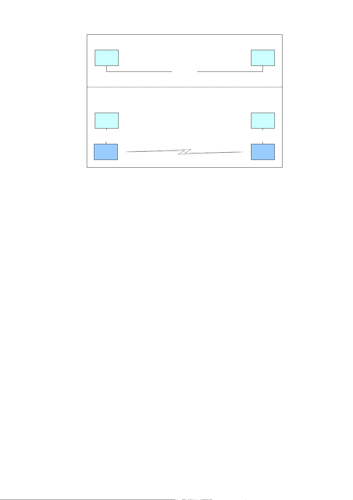
The Serial Port Profile is used to replace an RS-232 serial cable between two devices with a
Bluetooth connection. The physical setup is shown in Figure 3.
Bluegiga Proprietary, Copyright © Bluegiga Technologies 2001-2004 22 (94)
USER'S AND DEVELOPER'S GUIDE WRAP MULTIRADIO ACCESS SERVER
A)
User
device A
Serial Cable
User
device B
B)
User
device A
Serial
Cable
WRAP
DevA
Bluetooth
Figure 3. Serial Cable Replacement Physical Setup.
State A) in the figure is the starting situation with a serial cable connecting the devices. This
cable is to be replaced with a Bluetooth connection.
User
device B
Serial
Cable
WRAP
DevB
In state B) the long serial connection is replaced with a Bluetooth Serial Port Profile connection
between the two WRAP devices. These WRAP devices are then connected locally to the user
devices with (short) serial cables. The cable between user device A and WRAP device A must
be a cross-over cable. The cable between user device B and WRAP device B must be similar
(direct or cross-over) to the one used in state A).
If RTS/CTS handshaking is used to ensure correct data transfer, the serial cables must have
these pins connected. Note: This handshaking is "local": it takes place between the user
device and the WRAP board. No handshaking between user device A and user device B on the
other end of the Bluetooth connection is provided.
If RTS/CTS handshaking is not used, CTS must be connected to DTR.
DCD, DTR, and DSR signals are not supported. This also means that user devices A and B will
not be able to tell whether or not the Bluetooth connection is up.
When the physical setup is ready, you can create the Bluetooth connection. By default, the
Serial Port Profile is started up at boot with the default settings. That is, listening in DevB
mode, at 9600 bps, 8 data bits, no parity, 1 stop bit, and RTS/CTS enabled. To change these
settings, use the "setup" application, as described in section 3.1.2.3.
You can also start the Serial Port Profile manually by calling its init script: "/etc/init.d/spp
start".
Note: When the Serial Port Profile is enabled, the WRAP SMS Gateway Server can not be used,
as they share the same physical user serial port
4.1.4 O
BJECT PUSH AND FILE TRANSFER PROFILE
The WRAP also has two OBEX profiles: the Object Push Profile (ObjP) and the File Transfer
Profile (FTP). You can use these profiles to transfer files easily between different WRAP devices
and other devices supporting them.
Bluegiga Proprietary, Copyright © Bluegiga Technologies 2001-2004 23 (94)

USER'S AND DEVELOPER'S GUIDE WRAP MULTIRADIO ACCESS SERVER
These profiles are handled by forwarding incoming calls to "obexserver" program, which
handles both profiles. The OBEX working directory is /tmp/obex, and users have full read and
write access there. By default, that directory also contains the default vCard.
Two simple command line utilities, "obexput" and "obexget", are also provided. They can be
used to send and retrieve a single file to and from another Bluetooth device supporting OBEX.
Enter either of the commands without parameters to get a short help for using the command.
If the return value is non-zero, one of the following situations has happened: -2: --help, 2:
Invalid parameter, -3: Error connecting to control socket, -4: Failed talking to Bluetooth
Server, -1: Error connecting to data socket. Note that return value is zero (0) even if the OBEX
communication has failed. You should therefore scan the standard output of the command. On
error, you will see the OBEX error in format "Failed to <what>, errorcode <hexcode>" where
<what> can be "connect", "setpath", "put", "get" or "disconnect" and <hexcode> is the
obexclientlib return code in hexadecimal format for the corresponding command, documented
in 9.8.2.
4.1.5 PAN P
ROFILE
The WRAP Multiradio Access Server has support for all PAN profile modes: Personal Area
Network User (PANU), Network Access Point (NAP) and Group Node (GN).
The device creating the PAN connection decides, which of these modes are to be used.
Incoming connections are handled automatically by the WRAP. The WRAP board can also act as
a PAN Client, but in this case it must be controlled manually using the socket interface,
described in the Bluetooth developer documentation.
4.1.6 B
LUETOOTH RANGE CHANGING
The transmit power of the WRAP Multiradio Access is configurable. By default, class 1 (100
meter range) settings are used. The settings can be changed down to "class 2" settings (10
meter range) with "b2b_class2" command or even less with "b2b_class3" command. The class
1 settings can be restored with "b2b_class1" command.
After "b2b_classX" is given, it is recommended to reboot the WRAP once to restart Install Point
and other applications connected to the Bluetooth server(s).
Note: When the operation is successful, you should get one "Can't open baseband" message
with WRAP Multiradio Access Server model 2293 and three messages with 2291.
4.1.7 BTCLI - B
LUETOOTH SERVER COMMAND LINE INTERFACE UTILITY
You can send commands to a Bluetooth server using the "btcli" application.
Usage:
btcli [options] command
To see the options, enter the command "btcli --help".
The specified command is sent to a WRAP Bluetooth server (default: first server at port 10101)
and all replies are echoed to the standard output. The application waits and prints the replies
for a certain amount of time (default: 10 seconds) and exits.
4.1.8 S
ERIALBLUETOOTH
It is also possible to control the first WRAP Bluetooth server (at port 10101) via RS-232 with
the "serialbluetooth" application. Note: When you want to use this application, you must first
disable the Bluetooth Serial Port Profile and the WRAP SMS Gateway Server with the "setup"
application, as described in chapter 3.
Bluegiga Proprietary, Copyright © Bluegiga Technologies 2001-2004 24 (94)

USER'S AND DEVELOPER'S GUIDE WRAP MULTIRADIO ACCESS SERVER
Usage:
serialbluetooth [options]
To see the options, enter the command "serialbluetooth --help".
Basically, serialbluetooth takes commands from a serial port and forwards them to the
Bluetooth server. All the commands available via socket interface are also available via serial
port.
There are two exceptions:
1) After making an outgoing RFCOMM data call, all input from the serial port is forwarded to
the data socket, not the control socket. To close the data socket, you have to write "+++" with
a 200ms pause before each character. There is no way to have two concurrent RFCOMM calls.
2) All incoming RFCOMM calls are answered automatically. Again, to close the data socket,
write "+++" as with the outgoing call.
4.2 C
OMPACT FLASH GPRS CARD
The Compact Flash GPRS card is identified automatically by the operating system when
inserted. At that time, the device file "/dev/ttyS0" is created.
A GPRS connection is made with command "pppd call gprs" and closed by killing the pppd –
process handling the GPRS connection.
The connections settings are in the directory "/etc/ppp/peers". The default GPRS call settings
work with major Finnish operators (TeliaSonera, Radiolinja, DNA).
If needed for special use, the Compact Flash GPRS card can also be accessed directly from
"/dev/ttyS0".
4.2.1 SIM C
ARD’S PIN CODE
If your SIM card has PIN code checking enabled, insert the following line just after the line '""
AT' in file "/etc/ppp/peers/gprs.connect":
OK 'AT+CPIN="pincode"'
4.2.2 GPRS TROUBLESHOOTING
If you don’t get connection, check "/var/log/messages". To get more verbose error messages
from the GPRS modem, enable more verbose error codes by adding line "OK 'AT+CMEE=2'"
just after the line '"" AT' in file "/etc/pp/peers/gprs.connect".
4.2.3 C
Sometimes, the Compact Flash GPRS card does not get identified. Instead, an error message
"serial_cs: ParseTuple: Bad CIS tuple" appears at console and the device file "/dev/ttyS0" is
not created. This happens most likely because of timing problems but there is no fix available
yet.
ONSOLE MESSAGE "SERIAL_CS: PARSETUPLE: BAD CIS TUPLE"
As a workaround, one can force the identification process to restart with the command line: "[
! -c /dev/ttyS0 ] && cardctl eject && cardctl insert".
Bluegiga Proprietary, Copyright © Bluegiga Technologies 2001-2004 25 (94)

USER'S AND DEVELOPER'S GUIDE WRAP MULTIRADIO ACCESS SERVER
4.3 C
The WLAN configuration with "setup" application is not yet available. The currently supported
WLAN cards are "EZ Connect" by SMC Networks and "Instant Wireless" by Linksys. For this
kind of Prism II/III based CF WLAN cards there are two different drivers.
4.3.1 H
If your WLAN card firmware is 1.7.4, you have to use Hostap driver. It supports both client and
master modes. You can check the firmware version by inserting the card and entering
command "dmesg". If you see the following line among the latest ones, you have firmware
1.7.4:
OMPACT FLASH WLAN
OSTAP DRIVER
eth1: Looks like an Intersil firmware version 1.7.4
To select Hostap driver enter the following command (ignore errors):
[root@wrap /]$ mv /etc/pcmcia/hostap_cs.conf.hermes
/etc/pcmcia/hostap_cs.conf
To use the master mode create the file "/etc/sysconfig/wlan" with one line "DISABLE=no", for
example with the following command:
[root@wrap /]$ echo DISABLE=no > /etc/sysconfig/wlan
To configure the master mode to use encryption, add following lines (replace examples with
your ESSID and encryption key, which can be also shorter for 40/64bit encryption) to the file
"/etc/sysconfig/wlan":
WEPKEY="0123456789abcdef0123456789"
ESSID="myessid"
To use client mode create the file "/etc/sysconfig/wlan" with one line "DISABLE=yes", for
example with the following command:
[root@wrap /]$ echo DISABLE=yes > /etc/sysconfig/wlan
In client mode you also have to configure client settings in the file
"/etc/sysconfig/network.pcmcia", see below.
4.3.2 H
You have to use Hermes driver if your WLAN card firmware is below 1.7.4. Hermes supports
only client modes.
To select Hermes driver enter command (ignore errors):
ERMES DRIVER
[root@wrap /]$ mv /etc/pcmcia/hostap_cs.conf
/etc/pcmcia/hostap_cs.conf.hermes
To configure WLAN to use DHCP, create the file "/etc/sysconfig/network.pcmcia" with one line
"DHCP=y", for example with the following command:
[root@wrap /]$ echo "DHCP=y" > /etc/sysconfig/network.pcmcia
To configure WLAN with static network settings, create the file
"/etc/sysconfig/network.pcmcia" similar to this example configuration:
DHCP=n
IPADDR="10.0.0.41"
NETMASK="255.255.255.0"
NETWORK="10.0.0.0"
BROADCAST="10.0.0.255"
GATEWAY="10.1.1.254"
SEARCH="local.net"
Bluegiga Proprietary, Copyright © Bluegiga Technologies 2001-2004 26 (94)

USER'S AND DEVELOPER'S GUIDE WRAP MULTIRADIO ACCESS SERVER
DNS_1="10.1.1.1"
To configure WLAN to use encryption, add following lines (replace examples with your ESSID
and encryption key, which can be also shorter for 40/64bit encryption) to the file
"/etc/sysconfig/network.pcmcia"
0123456789abcdef0123456789"
ESSID="myessid"
After configuration, the WLAN interface comes up automatically when the WLAN card is
inserted. The WLAN interface is "eth1".
4.3.3 G
ENERAL CONFIGURATION
Standard set of wireless utilities are provided to fine-tune your WLAN configuration:
• iwconfig
• iwlist
• iwpriv
For more info see: http://www.hpl.hp.com/personal/Jean_Tourrilhes/Linux/Tools.html
4.4 S
ERVERS
The WRAP server applications are started automatically at system power-up or when needed
by the Bluetooth server or the Internet services daemon. The servers and their purposes are
described in Table 3.
Bluegiga Proprietary, Copyright © Bluegiga Technologies 2001-2004 27 (94)

USER'S AND DEVELOPER'S GUIDE WRAP MULTIRADIO ACCESS SERVER
Server Purpose
bluetooth WRAP Bluetooth Server, described in detail in section 9.
btcli WRAP Bluetooth Server Command Line Interface utility.
httpd Web server, described in detail in section 4.4.1.
installpoint WRAP Install Point server.
smsgw WRAP SMS gateway server, described in detail in section 4.4.2. Note: By default,
this server is not started at power-up.
watchdog WRAP user level watchdog.
wpkgd WRAP remote management system daemon.
cardmgr Daemon to monitor Compact Flash cards.
crond Daemon to execute scheduled commands. Configurable with /etc/crontab in the
same way as any Linux crond. Note: By default, this is disabled. Use "chkconfig -add cron" to enable.
ftpd Internet File Transfer Protocol Server. Configurable with /etc/stupid-ftpd/stupid-
ftpd.conf.
dhcpcd DHCP client daemon for automatic network configuration.
inetd Internet services daemon. Note: By default, this is disabled. Use "chkconfig --add
inet" to enable.
pppd Point to Point Protocol daemon. Used by the Bluetooth server. Can be used
manually over the user serial port (/dev/ttySA1).
sshd SSH daemon.
syslogd System logging daemon. Configurable with the setup application.
telnetd Telnet protocol server.
Table 3. WRAP Servers.
4.4.1 W
EB SERVER
The integrated web server in the Bluegiga WRAP supports HTTP/1.0 methods GET and POST,
and has light user authentication capabilities. The content can be either static or dynamic – the
WWW server is CGI/1.1 compatible.
The web server is always running and the content (http://wrap-ip-address/
) is located in the
/var/www/html/ directory in the WRAP file system. The directory can be changes using "setup"
–application, see subsection 3.1.5. By default, there is only a simple demonstration file,
index.html, there, but it can be replaced, and more directories and pages can be added.
For further information, see the web examples in section 8.1.
4.4.2 I
NSTALL POINT
The Install Point software is started automatically in the WRAP Multiradio Access Server. It
server two purposes:
1. Receives business cards (vCards), analyses their content and sends files back selecting
them based on configured keywords found.
2. Receives management packets and forwards them to the WRAP Package daemon. The
default configuration is empty, so no files can be requested with business cards.
Bluegiga Proprietary, Copyright © Bluegiga Technologies 2001-2004 28 (94)

USER'S AND DEVELOPER'S GUIDE WRAP MULTIRADIO ACCESS SERVER
4.4.2.1 I
NSTALL POINT CONFIGURATION
The Install Point is configured both by the "setup" application (the logging device / file, see 5)
Install Point Settings) and mainly with its configuration file, "/etc/installpoint.conf".
The configuration file can consists of the following lines:
'#' starts comment line
- # InstallPoint(tm) database file
'%' starts storage directory name definition (only one, last one used)
- %/var/lib/installpoint
All other lines are assumed to be "database" lines with four white space separated fields. When
a request vCard is received, it is parsed and these lines are scanned. If a match is found, a
filename specified is sent. There can be several matches, when several files can be sent. If the
request is not vCard or .wpk file, but for example a picture, it is handled as if it was empty
vCard.
filename
- filename to be sent, must locate in storage directory
"alias"
pincode
bdaddr
4.4.2.2 I
- string that must match in name field (first name or last name (N) or formatted
name (FN)) field in the vCard
- use "*" for accepting any
- NOTE: alias must be in quotes (as formatted name may contain spaces).
- pincode that must be in the preferred telephone (TEL;PREF) or voice telephone
(TEL;VOICE) number field in the vCard
- use '*' (with no quotes) for no pin code
- bdaddr that is allowed to ask for this file
- use '*' (with no quotes) for allowing anyone to request
NSTALL POINT EXAMPLE CONFIGURATION
# example installpoint config file
%/var/lib/installpoint
ipquery.wpk "ip" * *
<EOF>
With this configuration, anyone can send a vCard with "ip" in then name field, and the file
called "ipquery.wpk" is then sent back. The file "ipquery.wpk" must be located in the storage
directory "/var/lib/installpoint".
Bluegiga Proprietary, Copyright © Bluegiga Technologies 2001-2004 29 (94)

USER'S AND DEVELOPER'S GUIDE WRAP MULTIRADIO ACCESS SERVER
4.4.3 SMS G
ATEWAY SERVER
The WRAP SMS Gateway server supports Nokia 20, Nokia 30 or Wavecom WMOD2 compatible
GSM terminals for sending and receiving SMS messages. The device must be connected to the
user serial port when the server starts up. The terminals must be configured to operate in RS232/AT-command mode and the PIN code query of the SIM-card at power-up must be
disabled. The Nokia terminals are configured with the N20 or N30 Configurator application.
To enable the WRAP SMS Gateway Server, use the "setup" application, as described in section
3.1.6.
For further information on using "smsgw", see the "makesms" example in section 8.1.
Note: You must disable the Bluetooth Serial Port Profile before you can enable the WRAP SMS
Gateway Server, as they share the same physical user serial port.
Note2: You can use also the supported GSM/GPRS Compact Flash cards with the WRAP SMS
Gateway. Just edit "/etc/smsgw.conf" so that SMS GW will use the device "/dev/ttyS0" instead
of the default "/dev/ttySA1". Also remember that the PIN code query of the SIM-card must be
disabled.
4.4.4 U
SER LEVEL WATCHDOG
The WRAP User Level Watchdog daemon listens on UDP port 4266 for "id timeout" messages.
"id" is an ASCII string, without spaces. If "timeout" equals to 0 (zero), the "id" is removed
from the list of processes to wait. If "timeout" is greater than 0 (zero), the "id" is added or
updated.
When there is no message for "id" received within the "timeout" seconds, the user level
watchdog dies and the WRAP is rebooted by the kernel watchdog.
The "watchdog" command can be used to send messages to the watchdog daemon. This is
done via command "watchdog id timeout", for example "watchdog test 5".
4.4.5 R
EMOTE MANAGEMENT
The WRAP Multiradio Access Server contains simple tools that provide base for full and secure
remote management of the device.
4.4.5.1 O
VERVIEW
The WRAP Remote Management System top level architecture is shown in Figure 4.
Bluegiga Proprietary, Copyright © Bluegiga Technologies 2001-2004 30 (94)

USER'S AND DEVELOPER'S GUIDE WRAP MULTIRADIO ACCESS SERVER
WPKGD INBOX
/tmp/wpkgd/in
InstallPoint
FTP
Scp, Sftp
Rsync over SSH
Bluetooth
WPKG
processing
USB memory USB hotplug
WPKGD OUTBOX
InstallPoint
Bluetooth
Customer System
Figure 4. WRAP Remote Management Architecture.
A management action is performed using the following protocol:
/tmp/wpkgd/out
FTP
Scp, Sftp
Rsync over SSH
USB memory USB writer
1. A management packet (*.wpk) is prepared by the customer system.
2. The management packet is delivered to WRAP, into packaging daemon’s inbox
directory. One can currently use Bluetooth, Rsync over SSH, Scp, Sftp and plain FTP to
do this. Also some USB memory dongles are supported, see subsection 4.4.5.7.
3. The WRAP packaging daemon processes the management packet, possibly generating
reply packet into daemon's outbox.
4. (optional) Reply packet is delivered (or retrieved) to the customer system.
4.4.5.2 M
ANAGEMENT PACKET FORMAT
- Package name must be of format "name.wpk", where "name" can be user
defined.
- Package must be tar –archive that is compressed with gzip (like files named
*.tar.gz or *.tgz)
- Package must contain package information file called "wpkg.pif" in package root
(contents described later)
Bluegiga Proprietary, Copyright © Bluegiga Technologies 2001-2004 31 (94)

USER'S AND DEVELOPER'S GUIDE WRAP MULTIRADIO ACCESS SERVER
- Optional signature information file "wpkg.sig" may exist in package root (it is not
used yet though)
- All other files, if exist, should be data files, scripts or executables required for
the management operation
4.4.5.3 M
ANAGEMENT PACKET INFORMATION FILE FORMAT
The management packet information file (wpkg.pif) consists of tags and their data, described
here
%wpkg-version:0.0.1
- Must be the first line of the file. Contains information for version checking. 0.0.1
is currently the only version supported. Cannot be multi-line.
%wpkg-prepare:[command line[s]]
- One or more commands (all lines until next tag are interpreted as command
lines) to execute. Commands may contain parameters, but output redirection
and job control does not work.
%wpkg-output:[output line[s]]
- One or more lines of texts (all lines until next tag are interpreted as output lines)
to output. Useful mainly in interactive use (not in remote management).
4.4.5.4 M
ANAGEMENT SYSTEM ENVIRONMENT VARIABLES
The management system communicates to the management packets via environment
variables. As of version 0.0.1, two variables are supported and set by the system for user
scripts to use:
WPKG_OUTDIR:
- WPKGD OUTBOX directory, the place where the reply packet should be
generated.
WPKG_ORIGIN:
- file containing one line which identifies the sender of the management packet.
As of version 0.0.1, if Bluetooth was used to transmit the management packet
and this file is moved to "reply_packet_name.origin" in the WPKG_OUTDIR, the
reply packet is sent automatically.
4.4.5.5 M
ANAGEMENT OPERATION EXAMPLE: IPQUERY
In this example we build a simple packet that can be used with Bluetooth-enabled phone to
retrieve IP Address of the WRAP Multiradio Access Server. More (complex) examples will be
available soon.
The package consists of the following files (see ipquery.wpk, unpack it with "tar xzvf
ipquery.wpk"):
File "wpkg.pif":
- package information file, just tells to run "./ipquery" file.
Bluegiga Proprietary, Copyright © Bluegiga Technologies 2001-2004 32 (94)

USER'S AND DEVELOPER'S GUIDE WRAP MULTIRADIO ACCESS SERVER
File "functions":
- some reusable shell functions
File "ipvcard":
- script which outputs the serial number, ip address and hostname of the device in
vcard format that can be viewed with a mobile phone.
File "ipquery":
- the main script which calls "ipvcard" to generate response vcard and moves it
and the originator info file to WPKG_OUTDIR.
To use the example, send the file "ipquery.wpk" to the inbox of you Bluetooth phone. Check
that you have Bluetooth enabled in the phone. Then from the phone’s inbox, send the file
"ipquery.wpk" via Bluetooth to the WRAP Multiradio Access Server.
4.4.5.6 M
ANAGEMENT REPLY PACKET DESTINATION DEFINITION
The WRAP Package daemon (WPKGD) operates in a simple loop.
First it scans its inbox directory for files ending ".wpk" AND ".wpk.origin". When both of these
are found with similar beginning, the package is processed with "wpkg" command.
Then it scans its outbox for "filename" AND "filename.origin" files. If they both are found and
"filename.origin" contains supported address information (OBEX or USB currently), the reply
packet is send.
The content of the "filename.wpk.origin" file is one line of following formats:
"obex://bd:ad:dr:es:00:00/"
"usb://path/to/reply/"
"rsync://user@host.remote.domain:path/to/reply/"
"scp://user@host.remote.domain:path/to/reply/"
"ftp://user:password@host.remote.domain:path/to/reply/"
Currently the WRAP Package daemon can only automatically handle Bluetooth (OBEX) and USB
replies. Other replies must be retrieved from the remote site manually (from the WRAP
Package daemon’s outbox, /tmp/wrap/outbox/).
When a management packet is received via Bluetooth or USB in the future, the
"filename.wpk.origin" file is generated automatically.
If one wants to remotely execute management operations, the "filename.wpk.origin" file must
be created by oneself. So, to activate remote management operation, one must send the
management packet file ("filename.wpk") AND the management packet origin file
(“filename.wpk.origin”) into the WPKGD inbox directory.
Bluegiga Proprietary, Copyright © Bluegiga Technologies 2001-2004 33 (94)

USER'S AND DEVELOPER'S GUIDE WRAP MULTIRADIO ACCESS SERVER
4.4.5.7 M
ANAGEMENT WITH USB MEMORY DONGLE
When an USB memory dongle is inserted, the WRAP Multiradio Access Server automatically
tries to mount (using VFAT type) it. When the mount is successful, directory "/wpkgd/in" is
searched for a "*.wpk" packet and if the packet is found, it handled by the WRAP Package
daemon. Optional responses are sent to the directory "/wpkgd/out" in the USB dongle, or if
"out" does not exist, to the directory "/wpkgd".
NOTE: Not all dongels are currently supported and the testing of the dongles is still ongoing.
So far, Buffalo and Sandisk dongles have passed, but for example JetFlash dongles cannot get
mounted. Failure with a non-supported USB dongle may need system to be restarted for a
supported dongle to work.
4.4.6 FTP
By default, users can use FTP to log in anonymously to "/tmp/obex" -directory with download
access or as "root" with password "buffy" to the root directory with full access. The password
can be changed on the WRAP editing the file "/etc/stupid-ftpd/stupid-ftpd.conf".
4.4.7 SSH
By default, users can use SSH to log in (or SCP to transfer files) as "root" with any password.
The password can be changed on the WRAP using the command "passwd".
4.4.8 T
ELNET
By default, users can use telnet to log in as "root" without password. The password can be
changed on the WRAP using the command "passwd". The telnet port is the default, 23.
4.5 U
TILITIES
The WRAP is basically a small Linux system. Whether logged in from the management console
or with telnet, your shell session starts as the root user in the root directory. After that, you
have the option to use most of the standard Linux utilities, briefly listed and described in Table
4. Most of the commands have a small built-in usage help that can be seen by executing the
command with the "-h" or "--help parameter.
Bluegiga Proprietary, Copyright © Bluegiga Technologies 2001-2004 34 (94)

USER'S AND DEVELOPER'S GUIDE WRAP MULTIRADIO ACCESS SERVER
Application Purpose
adduser Add user to the system.
arping Ping hosts by ARP requests/replies.
awk Pattern scanning and processing language.
b2b_class1 WRAP Board2Board module control script (set basebands to class 1).
b2b_class2 WRAP Board2Board module control script (set basebands to class 2).
WRAP Board2Board module control script (set basebands to shortest possible
b2b_class3
range).
basename Strip directory and suffix from filenames.
bash Bourne-Again SHell.
btproxy WRAP Bluetooth Proxy for Multiradio access servers (test revision).
bunzip2 Decompress bzip2-compressed files.
bzcat Decompress bzip2-compressed files to stdout.
cardctl Monitor and control the state of PCMCIA sockets.
cat Concatenate files and print on the standard output.
chat Automated conversational script with a modem.
chgrp Change group ownership.
chkconfig Updates and dqueries runlevel information for system services.
chmod Change file access permissions.
chown Change file owner and group.
chroot Run command or interactive shell with special root directory.
clear Clear the terminal screen.
cmp Compare two files.
cp Copy files and directories.
cpio Copy files to and from archives.
crontab Maintain crontab files for individual users.
cut Remove sections from each line of files.
Print or set the system date and time. Note: The date command does not store
the date into the battery powered real time clock. Use hwclock application
date
instead.
dd Convert and copy a file.
deluser Delete user from the system.
df Report file system disk space usage.
dirname Strip non-directory suffix from file name.
dmesg Prints of controls the kernel ring buffer.
du Estimate file space usage.
Retrieves and parses the Card Information Structures for inserted PCMCIA
dump_cis
devices, or optionally, parses CIS information from a file.
egrep Print lines matching a pattern.
env Run a command in a modified environment.
expr Evaluate expressions.
false Do nothing, unsuccessfully.
fgrep Print lines matching pattern.
find Search for files in a directory hierarchy.
free Display the amount of free and used memory in the system.
ftp Internet file transfer program.
gdbserver Remote server for GDB debugger.
getty Opens a tty, prompts for a login name, then invokes /bin/login.
grep Print lines matching a pattern.
gunzip Expand gzip compressed files.
gzip Compress files into gzip format.
head Output the first part of files.
A filter which displays the specified files, or the standard input, if no files are
hexdump
specified, in a user specified format.
hostid Print out a unique 32-bit identifier for the machine (not yet implemented).
hostname Show or set the system's host name.
hwclock Query and set the hardware clock.
Bluegiga Proprietary, Copyright © Bluegiga Technologies 2001-2004 35 (94)

USER'S AND DEVELOPER'S GUIDE WRAP MULTIRADIO ACCESS SERVER
id Print information for username or current user.
ide_info IDE device information.
ifconfig Configure a network interface.
ifport Select the transceiver type for a network interface.
Checks to see if any of the listed hosts or network addresses are routed through
ifuser
the specified interface.
insmod Loads the specified kernel modules into the kernel.
ip TCP/IP interface configuration and routing utility.
iptables,
ip6tables
IP packet filter administration.
kill Terminate a program.
killall Kill processes by name.
ln Make links between files.
logger Make entries into the system log.
login Sign on.
logread Shows the messages from syslogd (using circular buffer).
ls List directory contents.
lsmod List loaded modules.
md5sum Compute and check MD5 message digest.
mkdir Make directories.
mknod Make block or character special files.
mktemp Make a temporary file name (unique).
modprobe High level handling of loadable modules.
more File perusal filter for crt viewing.
mount Mount a file system.
mv Move (rename) files.
nslookup Queries the nameserver for IP address of given host.
ntpclient Simple NTP client application.
obexbrowser The WRAP obexbrowser. A command line OBEX client interface.
The WRAP OBEX tool for retrieving a file from a remote device with ObjP/FTP
obexget
support.
The WRAP OBEX tool for sending a file to a remote device with ObjP/FTP
obexput
support.
Cconvert a text description of a PCMCIA Card Information Structure (CIS) to its
pack_cis
packed binary representation.
passwd Update a user’s authentication token(s).
picocom Minimal dumb-terminal emulation program.
pidof Find a process ID of a running program.
ping, ping6 Send ICMP ECHO_REQUEST packets to network hosts.
ps Report process status.
pwd Print the name of the current/working directory.
rb, rx, rz,
sb, sx, sz
Xmodem, Ymodem, Zmodem file receive and send.
rdate Get and possibly set the system date and time from a remote HOST.
reboot Reboot the system.
renice Alter the priority of running processes.
reset Resets the screen.
rm Remove files or directories.
rmdir Remove empty directories.
rmmod Unload loadable modules.
route Show / manipulate the IP routing table.
A file transfer program capable of efficient remote update
rsync
via a fast differencing algorithm.
scp Secure copy (remote file copy program).
scsi_info SCSI device description tool.
sed A Stream EDitor.
setup The WRAP Setup Application. See chapter 3.
Bluegiga Proprietary, Copyright © Bluegiga Technologies 2001-2004 36 (94)

USER'S AND DEVELOPER'S GUIDE WRAP MULTIRADIO ACCESS SERVER
sftp Secure file transfer program.
sleep Delay for a specified amount of time.
sort Sort lines of text files.
ssh, slogin OpenSSH SSH client (remote login program).
ssh-add Adds RSA or DSA identities to the authentication agent.
ssh-agent SSH authentication agent.
ssh-keygen SSH authentication key generation, management and conversion.
ssh-keyscan Gather SSH public keys.
strace Utility to trace system calls and signals.
strings Display printable strings in binary file.
stty Change and print terminal line settings.
su Run a shell with substitute user and group IDs.
sulogin Single-user login.
sync Flush filesystem buffers.
tail Output the last part of files.
tar Tar archiving utility.
tcpdump Utility for dumping traffic on a network.
telnet User interface to the TELNET protocol.
test Check file types and compare values.
time Run command and display it's resource usage information when finished.
top Provides view of processor activity in real time.
touch Change file timestamps.
tr Translate or delete characters.
traceroute Trace the route ip packets follow going to host.
true Do nothing, successfully.
tty Print the filename of the terminal connected to standard input.
uartmode WRAP Uartmode: Change the mode of the user serial port (DTE or DCE).
umount Unmount file systems.
uname Print system information.
uniq Remove duplicate lines from sorted lines.
unzip List, test, and extract compressed files in a ZIP archive.
uptime Tell how long the system has been running.
uudecode Decode a file create by uuencode.
uuencode Encode a binary file.
wc Print the number of bytes, words, and lines in files.
vi A text editor.
wget A utility to retrieve files from the World Wide Web.
The WRAP identification program. Shows build and hardware configuration
wrapid
information.
which Shows the full path of (shell) commands.
whoami Prints the user name associated with the current effective user id.
wpkg WRAP Package Management System.
zcat Expand gzip compressed files to the standard output.
xargs Build and execute command lines from the standard input.
Table 4. Utilities.
4.6 R
EAL TIME CLOCK
The system clock is read from the battery operated real time clock during boot. The time
between the system time and the real time clock can synchronized using the "hwclock"
application. Give command "hwclock --help" for more information.
Bluegiga Proprietary, Copyright © Bluegiga Technologies 2001-2004 37 (94)

USER'S AND DEVELOPER'S GUIDE WRAP MULTIRADIO ACCESS SERVER
4.7 T
IME ZONE
The default time zone in the WRAP Multiradio Access Server is UTC. You can change the
timezone by replacing the file "/etc/localtime" with the correct file from your desktop Linux
system (using your /etc/localtime or a wanted zone from /usr/share/zoneinfo).
4.8 S
YSTEM RE-INSTALL AND UPGRADE
The WRAP platform can be re-installed with the latest software version. The latest SW version
and instructions are available at http://www.bluegiga.com/techforum/
Bluegiga Proprietary, Copyright © Bluegiga Technologies 2001-2004 38 (94)

USER'S AND DEVELOPER'S GUIDE WRAP MULTIRADIO ACCESS SERVER
5 BLUETOOTH TECHNOLOGY OVERVIEW
Wireless Applications
TCP/IP
Wireless Applications
PPP / PAN
SDP RFCOMM
Logical Link Control and Adaption Protocol
Link Manager Protocoll (LMP)
Profiles
BGT Bluetooth API
(L2CAP)
HCI driver
Physical Bus Driver
HCI Firmware
Link Controller (LC)
BNEP
BT Upper
Layers
BaseBand
BT Lower
Layers
RF RF
Figure 5. Bluetooth Software and Hardware Components.
5.1 F
REQUENCY BANDS AND CHANNEL ARRANGEMENT
The Bluetooth system operates in the license-free 2.4 GHz ISM (Industrial Science Medial)
band using frequency hopping spread spectrum (FHSS). In the vast majority of countries
around the world this frequency band is 2400 – 2483.5 MHz. Some countries have, however,
national limitations on the frequency range. In order to comply with these national limitations,
special frequency hopping algorithms have been specified for these countries. It should be
noted that products implementing the reduced frequency band will not work with products
implementing the full band. Products implementing the reduced frequency band must therefore
be considered local versions.
Bluegiga Proprietary, Copyright © Bluegiga Technologies 2001-2004 39 (94)

USER'S AND DEVELOPER'S GUIDE WRAP MULTIRADIO ACCESS SERVER
The Bluetooth frequency band is divided into distinct channels with 1 MHz channel spacing. In
order to comply with out-of-band regulations in each country, a guard band is used at the
lower and upper band edge. The frequency range is 2.400 – 2483.5 MHz, and the
corresponding channels are f = 2402 + k MHz; k = 0 – 78. Transmission utilizes channel
hopping over the specified range at 1600 kHz hop frequency. When operating in countries that
permit the use of only a subset of the overall spectrum, transmission utilizes only the approved
portions of the spectrum. The Bluetooth system utilizes Gaussian frequency shift keying
(GFSK). The signaling rate is 1 Mbit/s.
5.2 P
OWER CONSIDERATIONS
The Bluetooth system transceivers are classified into three power classes to support different
link ranges.
• Power Class 1. Output power is 1 – 100 mW (0 – 20 dBm) with mandatory power
control ranging from 4 to 20 dBm.
• Power Class 2. Output power is 0.25 – 2.5 mW (-6 – +4 dBm) with optional power
control.
• Power Class 3. Output power is less than 1 mW (0 dBm) with optional power control.
Bluegiga’s WRAP products support a 100 meter link range with Option 1 (Power Class 1).
5.3 R
ADIO FREQUENCY PROPAGATION
The radio frequency signal propagates in free space as a spherical wave, from a point source
to all directions equally. In reality, the actual signal source always differs from a theoretic
isotropic signal source. The power distribution of wireless telecommunication equipment in
space is determined by the antenna radiation pattern. In free space the signal propagates with
the speed of light and attenuates with 1/r2 relation. In reality, the environment always differs
from free space. The propagation environment of wireless telecommunication equipment is
restricted by all obstacles.
The basic mechanism of radio propagation is attributed to reflection, diffraction, and scattering
depending on existing obstacles. Since the radio frequency signal propagates
omnidirectionally, the transmitted signal arrives at the receiver following multiple paths
deformed by the aforementioned propagation mechanisms. The received signal is the
superposition of attenuated and delayed replicas of the transmitted signal, leading to fading of
the transmitted signal and broadening of the duration of the transmitted pulse. The
transmitted pulse delay spread leads to inter-symbol interference (ISI) because the
subsequent symbols interfere with each other. The ISI leads to a bit error probability (BIT)
floor that is independent of the signal to noise ratio (SNR). Depending on the time delay
spread of the transmitted pulse or the amount of widening that the transmitted pulse
experiences across the radio channel, the multipath interference differs. When the time delay
spread of the transmitted signal is very small with respect to the signaling time, the multipath
interference essentially leads to the signal fading phenomena of the received signal. When the
time delay spread of the transmitted signal is high with respect to the signaling time, the
multipath interference leads to the symbol interference phenomena of the received signal as
well.
A major difference between indoor and outdoor environments is that the former is considerably
more sensitive to changes in the geometry of the environment than the latter. This is because
of the differences in distance between obstacles. For example, a door being shut rather than
open may have a major impact on an indoor environment whereas a comparable event in an
outdoor environment may have a minor impact.
Bluegiga Proprietary, Copyright © Bluegiga Technologies 2001-2004 40 (94)

USER'S AND DEVELOPER'S GUIDE WRAP MULTIRADIO ACCESS SERVER
The Bluetooth standard has been designed to operate in noisy radio frequency environments.
Transmission utilizes fast frequency hopping and short packages to make the link efficient and
robust. Fast hopping and short packages limit the impact of interfering devices on the same
frequency band.
Bluegiga Proprietary, Copyright © Bluegiga Technologies 2001-2004 41 (94)

USER'S AND DEVELOPER'S GUIDE WRAP MULTIRADIO ACCESS SERVER
6 INTRODUCTION TO SDK
This manual describes how to create and use applications using the WRAP Software
Development Environment. The relationship between the applications and the WRAP Software
and Hardware is shown in Figure 6.
Customer Applications
BGT APIs
Servers
BGT Core Engine
Operating system
Network Interfaces Local HW Interfaces
Figure 6. Relationship Between the Customer Applications and WRAP.
Bluegiga Proprietary, Copyright © Bluegiga Technologies 2001-2004 42 (94)

USER'S AND DEVELOPER'S GUIDE WRAP MULTIRADIO ACCESS SERVER
7 INSTALLING THE WRAP SOFTWARE DEVELOPMENT ENVIRONMENT
Note: The Software Development Environment can be installed only on a PC running the Linux
operating system!
7.1 WRAP S
The following hardware and software is required to run the WRAP Development Environment:
PC with
• CD-ROM drive
• Linux (tested with RedHat 6.2 and above, Fedora Core 1)
• 200MB of available hard disk space
An Ethernet connection to a Local Area Network (also connected to the WRAP board) is highly
recommended.
Mount the WRAP SDK CD-ROM or ISO image, change the current working directory to where it
is mounted, and run install as root.
Example (things you need to type are printed
$ (or mount –o loop /path/to/sdk2.iso /mnt/cdrom)
OFTWARE DEVELOPMENT ENVIRONMENT SYSTEM REQUIREMENTS
like this):
$ su -m (-m to keep original user's environment, will prompt for password)
$ mount /dev/cdrom /mnt/cdrom
$ cd /mnt/cdrom
$ sh install
Install will ask you some questions (described below) regarding which components to install
and the paths to install them to. If you are not very familiar with Linux, just press <enter> to
these questions (the default values are suitable for most users and systems).
7.2 Q
UESTIONS ASKED BY THE INSTALL SCRIPT
1. WRAP tools directory (default: /usr/local/arm)
This is the path where you want the WRAP Software Development tools (arm-linux-gcc,
etc.) to be installed.
Note: If you change this value, the WRAP tools and libc must be recompiled. The
recompilation process is very complicated and lengthy, and it may fail, depending on your
system. Recompilation is done automatically by the install script, if necessary.
2. Development directory (default: [home_of_current_user]/asdk)
This is the path where you want the WRAP Software Development Environment to be
installed.
3. Development directory owner (default: [current_user])
This is the username of the owner of the development directory.
Note: If this is not the username of the developer for whom the Software Development
Environment is being installed, the user will not have rights to use the development files
and therefore can not develop any WRAP software.
Bluegiga Proprietary, Copyright © Bluegiga Technologies 2001-2004 43 (94)

USER'S AND DEVELOPER'S GUIDE WRAP MULTIRADIO ACCESS SERVER
Install toolchain sources (default: no - unless the tools directory was
4.
changed)
Whether or not the toolchain sources will be installed. These are required only if the WRAP
tools directory was changed from the default target location in step 1.
Install Linux headers (default: no - unless libc sources are selected)
5.
Whether or not the Linux header files will be installed. These are required only if the libc
sources are being installed (chosen in step 5).
6. Install example applications (default: yes)
Whether or not the WRAP example applications and their sources will be installed.
7. Compile image after installation (default: yes)
If set to yes, install will compile the WRAP filesystem image to test that the installation
was successful and that the Development Environment is working correctly.
Bluegiga Proprietary, Copyright © Bluegiga Technologies 2001-2004 44 (94)

USER'S AND DEVELOPER'S GUIDE WRAP MULTIRADIO ACCESS SERVER
8 CREATING WRAP APPLICATIONS
The fastest way to start developing WRAP applications is to study, change, and recompile the
example files in the asdk/src/examples directory.
8.1 A
PPLICATION EXAMPLES
To demonstrate the software development features of the WRAP, the WRAP Software
Development Environment comes with several example applications.
8.1.1 I
NSTALLING EXAMPLES
The compiled example files are located on the WRAP SDK tree in the file
asdk\src\examples\examples.tar.gz. The examples can be manually uploaded and installed on
the WRAP board.
Uploading can be done with SCP, FTP or X/Y/Zmodem. After uploading, the examples archive
needs to be unpacked with the "tar xzvf" command before the files can be used.
8.1.2 R
UNNING EXAMPLES
After the example files have been transferred to the WRAP, they can be run from the directory
into which they were unpacked. The examples, with their usage and purpose, are described in
Table 5. Note: The example WWW pages must be transferred to the correct place, where the
Web server can find them. In this user manual it is assumed that this has been done by giving
the command "mv www/* /var/www/html" in the directory where the examples.tar.gz –file
was unpacked.
Bluegiga Proprietary, Copyright © Bluegiga Technologies 2001-2004 45 (94)

USER'S AND DEVELOPER'S GUIDE WRAP MULTIRADIO ACCESS SERVER
Example, source in
wrap/src/examples/
Usage, when installed to /tmp and
when it is the current directory Purpose
helloworld ./helloworld The "Hello, world!"
application.
serial ./serial /dev/ttySA1 "Hello, world!" to the serial
port.
btsend ./btsend – 12 on the first device,
./btsend <bdaddr of first> 12 on
second
Machine 2 Machine example.
"Hello, world!" over
Bluetooth. Note: Currently
uses "buffy" as Bluetooth
server password.
io/led
./led
I/O: LED/Buzzer example.
m2n echo testmessage | ./m2n Machine 2 Network example.
System Logger configuration
needed for actual remote
connection. Without it,
simulates it locally.
man2m ./ledserver &
browse with Java-enabled browser
to http://wrap-ip-adress/man2m/
Man 2 Machine example. Also
demonstrates Java applets.
Note: Assumes WWW pages moved
as guided.
www Browse to http://wrap-ip-address/
Note: Assumes WWW pages moved
Demonstration of the web
server capabilities.
as guided. More info on the page
itself.
makesms Browse to http://wrap-ip-
address/sms/
Note: Assumes WWW pages moved
as guided, "makesms" example
application is in /var/www/html/cgi-
Demonstrates WRAP SMS
Gateway by sending SMS
messages with required
Nokia N30 or N20 GSM
Terminal.
bin, and WRAP SMS Gateway is up
and running (see section 4.4.2).
obexbrowser Documented in chapter 9.8.3. Demonstrates the usage of
the WRAP OBEX libraries
implementing Object Push
Profile and File Transfer
Profile clients.
Table 5. Examples, Their Usage and Purpose.
If you do not want to re-install the example files after every system power-off, they can be
stored in the flash file system. Simply use the mv command to move the executables of the
examples you want to save into /usr/local/bin. After this, you can execute the examples from
anywhere (without the ./) and access the web examples directly under http://wrap-ip-
address/www/).
Bluegiga Proprietary, Copyright © Bluegiga Technologies 2001-2004 46 (94)

USER'S AND DEVELOPER'S GUIDE WRAP MULTIRADIO ACCESS SERVER
8.2 C
REATING A NEW PROJECT
To start a new project, you need to create a new subdirectory in your Development
Environment’s source directory (src/) and add your application source files and Makefile to that
directory. This can be done automatically using WRAP Access Server Project AppWizard. Just
give the command "make appwiz APP=dir/to/newapp" in the Development Environments top
level source directory (src/). A "hello world" example project is then created.
You can add your directory to the compile queue by inserting it in the file src/DIRECTORIES if
you want to compile the whole source tree at once from the top level src-directory.
You may need to modify the variables in the Makefile for your project. You can see the defaults
and their description in the default Makefile created by the AppWizard
(src/dir/to/newapp/Makefile in our example above).
• TOPLEVEL
This should point to the Development Environment source directory, i.e. src/.
• APPNAME
This is the name of the executable file of the application. In our example, this line should
be APPNAME = testapp
• SRC
This variable defines the files to be compiled and linked into APPNAME. In our example, this
line could be SRC = testapp.c. Several files are separated with space, like "SRC = testapp.c
extraobj.c"
• APP_STRIP
Optional variable. The application symbols are removed by default to reduce application
size. For debugging, these are needed, which can be done by "APP_STRIP=false".
• CFLAGS
Optional extra flags for C compiler. Set "CFLAGS=-ggdb" if you want to debug application.
• CXXFLAGS
Optional extra flags for C++ compiler. Set "CXXFLAGS=-ggdb" if you want to debug
application.
• LIBS
Optional additional libraries needed by application. Multihreaded application needs
libpthread with "LIBS=pthread".
Now you have a new project just waiting for coding. To compile the project, you simply need
to run make in the testapp directory.
8.3 B
UILDING FROM THE COMMAND LINE
The WRAP Development Environment uses the ARM port of the GNU bintools and compilers to
build applications. If you are not very familiar with Linux development, you should use the
method explained in section 8.2 instead of writing your own makefiles. If you still want to use
your very own development environment, there are two minor issues to remember:
Bluegiga Proprietary, Copyright © Bluegiga Technologies 2001-2004 47 (94)

USER'S AND DEVELOPER'S GUIDE WRAP MULTIRADIO ACCESS SERVER
1. Tools are prefixed with arm-linux-, so for calling gcc C-compiler you need to call armlinux-gcc, etc.
2. Tools are located in "/usr/local/arm/2.95.3/bin/" -directory, which is not in PATH by
default.
8.4 T
To run an application on the WRAP, it must first be transferred into the WRAP system. There
are several ways of doing this:
1. Over TCP/IP by FTP, SFTP, SCP (using Ethernet or Bluetooth)
2. Over management console by X/Y/Zmodem (using terminal software connected to the
3. Using NFS mount
8.4.1 T
FTP is a fast and easy way to upload an application to the WRAP. If you wish to use FTP for
transferring data to and from the WRAP, there has to be an FTP daemon running on the WRAP
connected to your LAN (if an Ethernet interface is used). Normally, this is the case.
After connecting to the WRAP FTP daemon, you need to decide where you want to put your
application – either on the ramdisk for testing purposes, or on the flash file system for
preserving your application between power-offs. The ramdisk is accessed through the ram
directory and the flash file system through the flash directory after logging in with FTP.
In the following example we will transfer our application to the /tmp directory (on the ramdisk)
using a simple FTP client. SFTP works similary. User input is shown
RANSFERRING AN APPLICATION TO WRAP HARDWARE
WRAP)
RANSFERRING AN APPLICATION TO WRAP USING (S)FTP OR SCP
like this.
$ ftp <wrap-ip-address>
Connected to <wrap-ip-address>.
220 Welcome to Stupid-FTPd server.
User (<wrap-ip>:(none)): root
331 Guest login ok, send your e-mail address as password.
Password: buffy (not echoed)
230 User anonymous logged in.
ftp> bin
200 Type set to I.
ftp> cd /tmp
250 CWD command successful.
ftp> put testapp
200 PORT command successful.
150 FILE: testapp
226 Transfer complete.
ftp: 133120 bytes sent in 0.91Seconds 145.96Kbytes/sec.
ftp> bye
221 Bye.
SCP transfer is done with command "scp testapp root@<wrapip-address>:/tmp
to save the application to /usr/local/bin (on the flash filesystem), you will have to replace
'/tmp' with '/usr/local/bin'. To examine the directory structure of the WRAP, please see
Appendix A.
". If you want
Bluegiga Proprietary, Copyright © Bluegiga Technologies 2001-2004 48 (94)

USER'S AND DEVELOPER'S GUIDE WRAP MULTIRADIO ACCESS SERVER
8.4.2 T
If your WRAP is not connected to a LAN, you may use terminal software of your own choice to
transfer data to the WRAP. The WRAP contains an X/Y/Zmodem protocol application, which
allows you to transfer data over the console using almost any terminal software available.
Example:
RANSFERRING AN APPLICATION TO WRAP USING TERMINAL SOFTWARE
1. Connect your computer to the WRAP management UART using a cross-over serial cable,
and start your terminal software (115 200bps, 8 data bits, no parity, 1 stop bit).
2. Change your working directory to where you want to upload your application, and run
the xmodem application with your application name as parameter.
3. Start Xmodem send from your terminal software.
[root@wrap /] cd /tmp
[root@wrap /tmp] rx testapp
rx: ready to receive testapp.
now start xmodem (checksum, not CRC) send from your terminal
[root@wrap /tmp]
If you want to save the application to /usr/local/bin (on the flash file system), you will have to
replace 'cd /tmp' with 'cd /usr/local/bin'. To examine the directory structure of the WRAP,
please see Appendix A.
8.4.3 U
To use NFS mount, have a NFS share prepared in your development PC and mount the
directory with command "mount -o nolock <dev-pc-ipaddress>:/nfsshare /mnt/nfs". After this,
you can access the share in directory "/mnt/nfs".
8.5 R
To run the application you just transferred to the WRAP, you need access to the WRAP Linux
console, either using terminal software connected to the WRAP management UART or using the
telnet connection (log in as "root" and remember the password, which is "buffy" by default).
After establishing a connection to the WRAP, change the directory to where your application is
located and change file permissions so that it can be executed, then run it.
Example:
SING NFS MOUNT
UNNING AN APPLICATION TRANSFERRED TO WRAP
[root@wrap /] cd /tmp
[root@wrap /tmp] chmod 755 testapp
[root@wrap /tmp] ./testapp
8.6 USING DEBUGGER (GDB/DDD)
It is possible to use GNU debugger GDB and a graphical user interface, like DDD, for
debugging applications in the WRAP Access Server.
You have to compile with debug options and without symbol stripping to make debugging
work. As mentioned above, this can be done by adding lines "APP_STRIP=false" and "CFLAGS
= -ggdb" to the Makefile below SRC line.
After you have compiled your application with these options and transferred your application to
WRAP, you can start debugging the application as follows:
1) Start gdbserver on the WRAP Access Server
Bluegiga Proprietary, Copyright © Bluegiga Technologies 2001-2004 49 (94)

USER'S AND DEVELOPER'S GUIDE WRAP MULTIRADIO ACCESS SERVER
gdbserver :<port> <your application>
Example: gdbserver :6789 ./testapp
2) Start debugger on the host PC. (example is for DDD)
ddd --debugger /usr/local/arm/2.95.3/bin/arm-linux-gdb
3) Load symbolfile from ddd’s gdb console:
Example: symbol-file testapp
4) Create connection to the debugserver
target remote <node IP>:<port>
Example: target remote 10.1.1.63:6789
5) Press lookup and start debugging
Bluegiga Proprietary, Copyright © Bluegiga Technologies 2001-2004 50 (94)

USER'S AND DEVELOPER'S GUIDE WRAP MULTIRADIO ACCESS SERVER
9 BLUETOOTH SERVER SOCKET INTERFACE
The Bluetooth in the WRAP is controlled via the TCP socket interface. The first Bluetooth server
is listening on port 10101. In case of WRAP 2293, the second Bluetooth server is listening on
port 10102 and the third one is listening on port 10103. All commands to a Bluetooth server
and replies from the server are plain ASCII strings ending in CR+LF ("\r\n"). Commands and
replies are not case sensitive.
When connecting to a server you must first wait for the "READY." prompt. Do not send any
commands prior to this. Some replies are broadcast to all clients of the server. If you see
something that you have not requested or that is not intended for your client (identified by the
link identifier), simply ignore the reply.
Normally, the Bluetooth Server Socket Interface is not protected with a password. The
password can be enabled and changed: see the SET command below. If the password is
enabled, it must be sent first, immediately following the "READY." prompt, to the Bluetooth
server. Otherwise, all commands will fail.
For an example of using the Bluetooth Server Socket Interface, please see
src/examples/btsend in the SDK directory.
9.1 T
ERMS
Bluetooth address (bdaddr) is six hex digits separated by a colon. For example,
"1a:2b:3c:4d:5e:6f". With commands requiring Bluetooth address, you can also use Bluetooth
friendly name instead.
Bluetooth channels are numbered from 1 to 30. In WRAP, the Serial Port Profile is assigned to
channel number two, the Object Push/File Transfer Profile to channel number three and the
LAN Access Profile is on channel number four. The other channels are free for user
applications.
Link Identifier (link_id) is a number from 0 to 99 used to identify established Bluetooth
connections.
9.2 S
TARTING THE BLUETOOTH SERVERS
Normally, the Bluetooth servers are started automatically upon power-up. You can restart the
servers manually (for example, to apply the changes made to the Bluetooth settings with
"setup" application without rebooting the system). To restart the servers manually, execute
the startup script with option "restart":
/> /etc/init.d/bluetooth restart
When the Bluetooth servers start up, it uses the settings configured with the "setup"
application described in the User manual. You can put your extra Bluetooth Server Socket
Interface commands in the /etc/bluetooth.conf file. The commands in that file are processed as
the last task every time each Bluetooth server is started.
9.3 B
ASIC COMMANDS
These commands are used for searching for and inquiring about nearby Bluetooth devices and
for controlling the Bluetooth server and/or the control connection itself.
Bluegiga Proprietary, Copyright © Bluegiga Technologies 2001-2004 51 (94)

USER'S AND DEVELOPER'S GUIDE WRAP MULTIRADIO ACCESS SERVER
In the following examples, lines starting with C: are commands sent by the client to the
Bluetooth server and lines starting with S: are replies received from the Bluetooth server by
the client.
Bluegiga Proprietary, Copyright © Bluegiga Technologies 2001-2004 52 (94)

USER'S AND DEVELOPER'S GUIDE WRAP MULTIRADIO ACCESS SERVER
9.3.1 I
NFO
INFO is used to retrieve version info of the Bluetooth server, in the same format as the READYprompt when the control connection is opened.
Command: INFO Reply: READY. (wrap-2-0-3 $Revision: 1.289 $ bt1.1)
Bluegiga Proprietary, Copyright © Bluegiga Technologies 2001-2004 53 (94)

USER'S AND DEVELOPER'S GUIDE WRAP MULTIRADIO ACCESS SERVER
9.3.2 I
INQUIRY is used to search for other Bluetooth devices. Timeout is in units of 1.25 seconds. If
an optional "NAME" parameter is provided, the NAME command will be sent automatically to all
found devices.
During the inquiry, all devices are listed as soon as they are found with "INQUIRY_PARTIAL"
replies. If the friendly name of the device found has been cached by the Bluetooth server, it is
also displayed. When the inquiry times out, a summary is displayed (how many devices were
found and their information repeated).
Command: INQUIRY timeout {NAME}
Reply: INQUIRY_PARTIAL bdaddr_of_dev_1 class_of_dev_1 "friendly name" rssi
...
INQUIRY_PARTIAL bdaddr_of_dev_n class_of_dev_n "friendly name" rssi
...
INQUIRY bdaddr_of_dev_n class_of_dev_n "friendly name"
NQUIRY
INQUIRY_PARTIAL bdaddr_of_dev_2 class_of_dev_2 "friendly name" rssi
INQUIRY number_of_devices_found
INQUIRY bdaddr_of_dev_1 class_of_dev_1 "friendly name"
INQUIRY bdaddr_of_dev_2 class_of_dev_2 "friendly name"
Example: S: READY.
C: INQUIRY 10
S: INQUIRY 0
C: INQUIRY 10
S: INQUIRY_PARTIAL 00:11:22:33:44:55 120300 "willow" 255
S: INQUIRY_PARTIAL 11:22:33:44:55:66 520204 "" 255
S: INQUIRY 2
S: INQUIRY 00:11:22:33:44:55 120300 "willow"
S: INQUIRY 11:22:33:44:55:66 520204 ""
C: INQUIRY 10 NAME
S: INQUIRY_PARTIAL 00:11:22:33:44:55 120300 "" 255
S: INQUIRY_PARTIAL 11:22:33:44:55:66 520204 "buffy" 255
S: INQUIRY 2
S: INQUIRY 00:11:22:33:44:55 120300 ""
S: INQUIRY 11:22:33:44:55:66 520204 "buffy"
S: NAME 00:11:22:33:44:55 "willow"
S: NAME 11:22:33:44:55:66 "buffy"
Bluegiga Proprietary, Copyright © Bluegiga Technologies 2001-2004 54 (94)

USER'S AND DEVELOPER'S GUIDE WRAP MULTIRADIO ACCESS SERVER
9.3.3 N
You can ask for the friendly name of another Bluetooth device with the NAME command.
Command: NAME bdaddr
Reply: NAME bdaddr "friendly name"
AME
NAME ERROR bdaddr reason_code more_info
Example: S: READY.
C: NAME 11:22:33:44:55:66
S: NAME 11:22:33:44:55:66 "buffy"
C: NAME 11:22:33:44:55:77
S: NAME ERROR 11:22:33:44:55:77 108 HCI_ERR_PAGE_TIMEOUT
Bluegiga Proprietary, Copyright © Bluegiga Technologies 2001-2004 55 (94)

USER'S AND DEVELOPER'S GUIDE WRAP MULTIRADIO ACCESS SERVER
9.3.4 Q
UIT
To close the connection to the Bluetooth server, use the QUIT command.
Command: QUIT Reply: There is no reply.
Example: S: READY.
C: QUIT
Bluegiga Proprietary, Copyright © Bluegiga Technologies 2001-2004 56 (94)

USER'S AND DEVELOPER'S GUIDE WRAP MULTIRADIO ACCESS SERVER
yp
9.3.5 S
ET
The SET command allows you to alter various Bluetooth and server parameters. The supported
parameters are listed in Table 6. Issuing a SET command without parameters will list the
current settings.
Topic Name Value Description
BLUETOOTH BDADDR bdaddr Our bdaddr. This is a read-only value.
BLUETOOTH NAME friendly_name Set your friendly name. Others can
request this name with the NAME
command. There are following meta
characters you can use:
*: Hardware serial number, last three
digits
$s: Hardware serial number, last three
digits
$S: Hardware serial number, all digits
$p: Server port, last digit
$P: Server port
$h: hostname
$H: FQDN
$$: $
$*: *
The default value is $S_$p.
BLUETOOTH READABLE mode If enabled, some SDP result codes will
have literal values instead of numeric
values.
0: No (always use numeric values)
1: Yes (literal values)
BLUETOOTH CLASS value Set class-of-device value.
BLUETOOTH ROLE role {policy
{timeout}}
Set master/slave role switch preference,
optionally also link policy
and link supervision timeout. Possible
values for "role" are:
0: allow calling, don’t request when
answering
1: allow calling, request when
answering
2: don’t allow calling, request when
answering
The default link policy is 000f and the
default link supervision timeout is 7d00.
See Bluetooth Core Specification 1.1 for
more information on these.
BLUETOOTH ENCRYPT value Whether or not to use Bluetooth
encryption. To actually have Bluetooth
encr
tion enabled, the connection has
Bluegiga Proprietary, Copyright © Bluegiga Technologies 2001-2004 57 (94)

USER'S AND DEVELOPER'S GUIDE WRAP MULTIRADIO ACCESS SERVER
g
to be authenticated.
0: No
1: Yes
BLUETOOTH PAGEMODE mode
{page_timeout
{page_scan_rep
etition_mode}}
Pagemode controls whether or not other
devices can find and call you. There are
four different modes:
0: No inquiry, no paging
1: Inquiry, no paging
2: No inquiry, paging
3: Inquiry and paging
Page timeout is in hex and the default
value is 2000. Default page scan
repetition mode is 2 (R2).
See Bluetooth Core Specification 1.1 for
more information on these.
BLUETOOTH AUTH * Remove default PIN code. If you are
making an outgoing connection and the
remote asks for PIN, "1234" will be
sent. If somebody is connecting to you,
no PIN will be requested.
BLUETOOTH AUTH * pin Set default PIN code. If you are making
an outgoing connection, this PIN code
will be sent. If somebody is connecting
to you, this PIN code is requested and,
if not supplied, the connection will be
refused.
BLUETOOTH AUTH bdaddr Remove PIN code for bdaddr.
BLUETOOTH AUTH bdaddr pin Set PIN code for bdaddr. See above for
functionality.
BLUETOOTH PAIR bdaddr linkkey Manually set linkkey for bdaddr.
BLUETOOTH PAIR bdaddr Manually delete linkkey for bdaddr.
BLUETOOTH PAIREXPIRE seconds Set expiration time, in seconds, for
pairing information.
BLUETOOTH LISTEN channel cmd
{mem {delay}}
Add fork-listener for the channel. When
there is an incoming RFCOMM
connection to the channel Bluetooth
server will handle the connection by
itself by forking "cmd". At least "mem"
kilobytes of free memory must be
available, or the connection will be
rejected. After forking Bluetooth server
will wait "delay" timerticks (50ms)
before transmitting any data.
The client application should modify
both the stdout and stdin pipes and set
NOECHO, 8BIT and all other necessary
modes in the very beginning. The
purpose of the "delay" parameter is to
ive the application enough time to do
Bluegiga Proprietary, Copyright © Bluegiga Technologies 2001-2004 58 (94)

USER'S AND DEVELOPER'S GUIDE WRAP MULTIRADIO ACCESS SERVER
this.
BLUETOOTH LISTEN psm L2CAP Add L2CAP-listener for the psm.
BLUETOOTH LISTEN channel Remove fork/L2CAP-listener for the
channel/psm.
BLUETOOTH LINK mode params Modify slaves powermode according to
"mode". "params" are optional and
mode-dependent. Possible values for
"mode" are 0, 1, 2, 3, 4:
0: Active.
Params: None.
1: Park: Round-robin.
Params: max_beacon min_beacon
sleep_after_unpark sleep_after_round
Defaults: 254 160 5 30
Sleeps are specified by timerticks
(50ms).
2: Park: Idle.
Params: max_beacon min_beacon
max_active
Defaults: 512 384 6
max_active is the maximum number of
active slaves.
3: Sniff: All.
Params: max_interval min_interval
attempt timeout
Defaults: 640 426 1 8
4: Sniff: Idle.
Params: idle_timeout max_interval
min_interval attempt timeout
Defaults: 400 640 426 1 32
idle_timeout is in timerticks (50ms).
See Bluetooth Core Specification 1.1 for
more information on params.
BLUETOOTH QOS service_type
token_rate
peak_bandwidth
latency
delay_variation
Set default QoS values for new
connection. Parameters are in hex. See
Bluetooth Core Specification 1.1 for
more information on params.
Defaults: 01 00000000 00000000 ffffffff
ffffffff
L2CAP TIMEOUT flushto linkto Define FlushTimeout and LinkTimeout
for L2CAP connections. See Bluetooth
Bluegiga Proprietary, Copyright © Bluegiga Technologies 2001-2004 59 (94)

USER'S AND DEVELOPER'S GUIDE WRAP MULTIRADIO ACCESS SERVER
Core Specification 1.1 for more
information on params.
Defaults: 65535 40000
PPP AUTH Don't require any PPP authentication on
incoming connections.
PPP AUTH username
password
Require specified username:password
on incoming PPP connections.
PPP CHANNEL channel Our PPP (LAN Access Profile) channel.
This channel will be handled internally
by the Bluetooth server. If you change
this, remember to modify the SDP
record as well. Use zero value to disable
the LAN Access Profile.
PPP DEFAULTROUTE value This setting controls whether or not the
Bluetooth server should modify the
defaultroute setting. There are four
different modes:
0: Don't alter defaultroute
1: Set defaultroute according to
outgoing PPP
2: Set defaultroute according to
incoming PPP
3: Set defaultroute according to all PPP
calls
PPP WINHANDSHAKE seconds Timeout to wait for the Windows RAS
handshake.
PPP IP ipaddr/mask Set network IP range for PPP clients.
PAN ENABLE bitmap Controls incoming PAN connections.
Bitmap:
1: Allow incoming PAN-PANU
connection.
2: Allow incoming PAN-GN connection.
4: Allow incoming PAN-NAP connection.
For most cases value "6" (the default) is
recommended.
CONTROL PASSWORD Don’t require password from control
clients (default)
CONTROL PASSWORD pass Enable password. Control connection
clients must send this password before
giving any other command. The
password is case sensitive.
CONTROL PING seconds If enabled (seconds > 0), the Bluetooth
server will send a "PING" reply to all
control connection clients. You have to
reply to it with "PONG" or the
connection will be closed.
link_id MSC value Set MSC for link_id to value. See ETSI
TS 101 369 (GSM 07.10) for more
information.
Bluegiga Proprietary, Copyright © Bluegiga Technologies 2001-2004 60 (94)

USER'S AND DEVELOPER'S GUIDE WRAP MULTIRADIO ACCESS SERVER
link_id ACTIVE Set powermode for link_id to active.
link_id PARK params Set powermode for link_id park.
Required "params" are:
avg_beacon or
max_beacon min_beacon
See Bluetooth Core Specification 1.1 for
more information on params.
link_id HOLD params Set link's powermode to hold. Required
"params" are:
avg or
max min
See Bluetooth Core Specification 1.1 for
more information on params.
link_id SNIFF params Set powermode for link_id to sniff.
Required "params" are:
avg_interval or
max_interval min_interval or
max_interval min_interval attempt or
max_interval min_interval attempt
timeout
Default attempt is 1, default timeout is
8.
See Bluetooth Core Specification 1.1 for
more information on params.
link_id QOS service_type
token_rate
peak_bandwidth
latency
delay_variation
link_id MASTER Switch role to master.
link_id SLAVE Switch role to slave.
Table 6. Supported Parameters of Bluetooth SET Command.
Command:
Reply: When there are parameters, there is no reply.
SET {topic name {value}}
Set link's QoS values. Parameters are in
hex.
See Bluetooth Core Specification 1.1 for
more information on params.
Example: S: READY.
C: SET BLUETOOTH NAME Buffy
C: SET BLUETOOTH PAGEMODE 3
C: SET BLUETOOTH READABLE 1
C: SET BLUETOOTH CLASS 020300
C: SET BLUETOOTH ROLE 0
C: SET BLUETOOTH ENCRYPT 0
C: SET BLUETOOTH PAGEMODE 3
C: SET BLUETOOTH AUTH * 1234
C: SET BLUETOOTH AUTH 00:11:22:33:44:55 4242
Bluegiga Proprietary, Copyright © Bluegiga Technologies 2001-2004 61 (94)

USER'S AND DEVELOPER'S GUIDE WRAP MULTIRADIO ACCESS SERVER
C: SET BLUETOOTH AUTH *
C: SET BLUETOOTH PAIREXPIRE 600
C: SET BLUETOOTH LISTEN 1 /bin/login 200
C: SET BLUETOOTH LISTEN 2 "my/own/command with parameters" 100 5
C: SET BLUETOOTH LISTEN 3
C: SET PPP DEFAULTROUTE 0
C: SET PPP AUTH buffy willow
C: SET PPP AUTH
C: SET PPP CHANNEL 4
C: SET PPP WINHANDSHAKE 10
C: SET PPP IP 192.168.166.0/24
C: SET 0 MSC 8d
C: SET CONTROL PING 60
S: PING
C: PONG
C: SET CONTROL PASSWORD
C: SET CONTROL PASSWORD buffy
<client reconnects>
S: READY.
C: SET
S: ERROR PASSWORD NEEDED.
<client reconnects>
S: READY.
C: buffy
C: SET
S: SET BLUETOOTH BDADDR 00:11:22:33:44:55
S: SET BLUETOOTH NAME Buffy
S: SET PPP AUTH
S: SET CONTROL PASSWORD buffy
S: SET
Bluegiga Proprietary, Copyright © Bluegiga Technologies 2001-2004 62 (94)

USER'S AND DEVELOPER'S GUIDE WRAP MULTIRADIO ACCESS SERVER
9.3.6 P
The PING command is used to check that the connection to the Bluetooth server is alive.
Command: PING Reply: PONG
ING
Example: S: READY.
C: PING
S: PONG
Bluegiga Proprietary, Copyright © Bluegiga Technologies 2001-2004 63 (94)

USER'S AND DEVELOPER'S GUIDE WRAP MULTIRADIO ACCESS SERVER
9.3.7 P
The PONG command has to be sent back if you see a PING reply from the server. If you do not
answer, the connection will be closed after a few seconds.
Command:
Reply: There is no reply.
ONG
PONG
Example: S: READY.
S: PING
C: PONG
Bluegiga Proprietary, Copyright © Bluegiga Technologies 2001-2004 64 (94)

USER'S AND DEVELOPER'S GUIDE WRAP MULTIRADIO ACCESS SERVER
9.3.8 S
To close the Bluetooth server you can use the SHUTDOWN command. This also immediately
closes all active connections.
Command:
Reply: There is no reply.
Example:
HUTDOWN
SHUTDOWN
S: READY.
C: SHUTDOWN
Bluegiga Proprietary, Copyright © Bluegiga Technologies 2001-2004 65 (94)

USER'S AND DEVELOPER'S GUIDE WRAP MULTIRADIO ACCESS SERVER
9.3.9 S
SLEEP waits for a specified number of seconds before processing further commands.
It is only usable in rc scripts (/etc/bluetooth.conf).
Command:
Reply: There is no reply.
LEEP
SLEEP seconds
Example: S: READY.
C: SLEEP 4
Bluegiga Proprietary, Copyright © Bluegiga Technologies 2001-2004 66 (94)

USER'S AND DEVELOPER'S GUIDE WRAP MULTIRADIO ACCESS SERVER
9.4 C
9.4.1 C
The CALL command is used to call other Bluetooth devices. It returns the link identifier (with
an immediate reply), which will be used in subsequent commands and replies.
Always make sure you check for a correct link_id before processing replies further.
You can use the special "FORK" call type to create an RFCOMM connection and automatically
launch an application which gets the RFCOMM connection bound to its standard input and
output. The client application should modify both the stdout and stdin pipes and set NOECHO,
8BIT and all other necessary modes in the very beginning.
Note 1: There can be only one pending CALL at any time, you have to wait for CONNECT/NO
CARRIER before issuing another CALL.
Note 2: PPP is "raw" PPP without any special handshaking. WINPPP is a Windows RAS
handshake followed by raw PPP. If you are unsure, use WINPPP.
Command:
ONNECTION COMMANDS AND REPLIES
ALL
CALL bdaddr SDP
CALL bdaddr psm L2CAP
CALL bdaddr channel RFCOMM
CALL bdaddr uuid RFCOMM
CALL bdaddr channel PPP
CALL bdaddr uuid PPP
CALL bdaddr channel PPP username password
CALL bdaddr uuid PPP username password
CALL bdaddr channel WINPPP
CALL bdaddr uuid WINPPP
CALL bdaddr channel WINPPP username password
CALL bdaddr uuid WINPPP username password
CALL bdaddr channel FORK /full/path/to/command
CALL bdaddr uuid FORK /full/path/to/command
CALL bdaddr channel FORK "/full/path/to/command and parameters"
CALL bdaddr uuid FORK "/full/path/to/command and parameters"
CALL bdaddr PAN-destUUID
CALL bdaddr PAN-destUUID PAN-srcUUID
Reply: CALL link_id
Example: S: READY.
C: CALL 00:11:22:33:44:55 SDP
S: CALL 0
S: CONNECT 0 SDP
C: CALL 00:11:22:33:44:55 4 PPP
S: CALL 1
S: CONNECT 1 SDP
C: CALL NameOfOtherDevice LAN PPP
S: CALL 1
S: CONNECT 1 SDP
C: CALL 00:11:22:33:44:55 4 WINPPP buffy willow
S: CALL 2
S: CONNECT 2 PPP
Bluegiga Proprietary, Copyright © Bluegiga Technologies 2001-2004 67 (94)

USER'S AND DEVELOPER'S GUIDE WRAP MULTIRADIO ACCESS SERVER
C: CALL 00:11:22:33:44:55 1 RFCOMM
S: CALL 3
S: CONNECT 3 RFCOMM 1042
C: CALL 00:11:22:33:44:55 2 FORK /bin/login
S: CALL 4
S: CONNECT 4 FORK
C: CALL 00:11:22:33:44:66 PAN-NAP
S: CALL 5
S: CONNECT 5 PAN-NAP
C: CALL 00:11:22:33:44:77 PAN-NAP PAN-NAP
S: CALL 6
S: CONNECT 6 PAN-NAP
Bluegiga Proprietary, Copyright © Bluegiga Technologies 2001-2004 68 (94)

USER'S AND DEVELOPER'S GUIDE WRAP MULTIRADIO ACCESS SERVER
9.4.2 C
CONNECT is not a command, but rather a reply broadcast to you when CALL successfully
makes the connection. Remember to check that the link_id matches your CALL!
On RFCOMM/L2CAP connections, there is an additional parameter called port. It is the TCP
socket port number, which is used to send and receive data to and from the remote device.
Connect to the port just like you connected to the Bluetooth server. The connection is "raw",
which means that no processing of incoming or outgoing data is made.
Note: In case of L2CAP connections, the data is handled as packets. Therefore both the
incoming and outgoing data must follow the format "HDR+L2CAPDATA", where HDR is two
bytes; first the low byte and then the high byte of the length of the L2CAPDATA packet and
L2CAPDATA contains the actual L2CAP-packet.
Command: This is not a command.
Reply:
ONNECT
CONNECT link_id SDP
CONNECT link_id RFCOMM port
CONNECT link_id L2CAP port
CONNECT link_id PPP
CONNECT link_id FORK
CONNECT link_id PAN-PANU
CONNECT link_id PAN-GN
CONNECT link_id PAN-NAP
Example:
S: READY.
C: CALL 00:11:22:33:44:55 SDP
S: CALL 0
S: CONNECT 0 SDP
C: CALL 00:11:22:33:44:55 4 PPP
S: CALL 1
S: CONNECT 1 PPP
C: CALL 00:11:22:33:44:55 1 RFCOMM
S: CALL 2
S: CONNECT 2 RFCOMM 1042
<Client can open socket connection to port 1042>
C: CALL 00:11:22:33:44:55 2 FORK /bin/login
S: CALL 3
S: CONNECT 3 FORK
C: CALL 00:11:22:33:44:66 PAN-NAP
S: CALL 5
S: CONNECT 5 PAN-NAP
C: CALL 00:11:22:33:44:77 PAN-NAP PAN-NAP
S: CALL 6
S: CONNECT 6 PAN-NAP
Bluegiga Proprietary, Copyright © Bluegiga Technologies 2001-2004 69 (94)

USER'S AND DEVELOPER'S GUIDE WRAP MULTIRADIO ACCESS SERVER
9.4.3 N
NO CARRIER-reply indicates that you or the remote device closed the active connection, or
that your CALL failed for some reason.
See 9.7 for the list of reason codes. Field "more_info" is optional. If present it gives you a
human readable error code or some statistics about the closed connection.
Command: This is not a command.
Reply:
O CARRIER
NO CARRIER link_id ERROR reason
NO CARRIER link_id
Example: S: READY.
C: CALL 00:11:22:33:44:55 4 PPP
S: CALL 0
S: NO CARRIER 0 ERROR 104 HCI_ERR_PAGE_TIMEOUT
C: CALL 00:11:22:33:44:55 1 RFCOMM
S: CALL 1
S: CONNECT 1 RFCOMM 1042
...
S: NO CARRIER 1 ERROR 000 IN=42,OUT=66,ELAPSED=69
Bluegiga Proprietary, Copyright © Bluegiga Technologies 2001-2004 70 (94)

USER'S AND DEVELOPER'S GUIDE WRAP MULTIRADIO ACCESS SERVER
9.4.4 R
The RING reply indicates an incoming CALL from a remote device. As with CONNECT, on
RFCOMM/L2CAP calls there is an additional port parameter. Connect to it if you want to serve
this call. PPP and PAN calls are handled internally so you don't have to do anything about
them. The Bluetooth server closes the connection if nobody grabs the call within 30 seconds.
Command: This is not a command.
Reply:
ING
RING link_id bdaddr channel PPP
RING link_id bdaddr channel RFCOMM port
RING link_id bdaddr psm L2CAP port
RING link_id bdaddr PAN-PANU
RING link_id bdaddr PAN-GN
RING link_id bdaddr PAN-NAP
Example: S: READY.
S: RING 0 00:11:22:33:44:55 4 PPP
S: RING 1 00:11:22:33:44:55 1 RFCOMM 1042
<Client can open socket connection to port 1042>
S: RING 2 00:11:22:33:44:55 PAN-GN
Bluegiga Proprietary, Copyright © Bluegiga Technologies 2001-2004 71 (94)

USER'S AND DEVELOPER'S GUIDE WRAP MULTIRADIO ACCESS SERVER
9.4.5 C
The CLOSE command closes an active connection started with CONNECT or RING. Note that
closing the RFCOMM data socket connection also closes the Bluetooth connection.
Command:
Reply: There is no direct reply. NO CARRIER is replied when the connection actually closes.
LOSE
CLOSE link_id
Example: S: READY.
C: CALL 00:11:22:33:44:55 4 PPP
S: CALL 1
S: CONNECT 1 PPP
C: CLOSE 1
S: NO CARRIER 1 ERROR 000
Bluegiga Proprietary, Copyright © Bluegiga Technologies 2001-2004 72 (94)

USER'S AND DEVELOPER'S GUIDE WRAP MULTIRADIO ACCESS SERVER
9.4.6 L
The LIST command reports active connections as well as some statistics.
Command: LIST Reply: LIST number_of_connections
IST
LIST link_id status type blocksize bytes_in bytes_out elapsed_time
our_msc remote_msc bdaddr channel direction powermode role crypt
LIST link_id status type blocksize bytes_in bytes_out elapsed_time
our_msc remote_msc bdaddr channel direction powermode role crypt
...
LIST link_id status type blocksize bytes_in bytes_out elapsed_time
our_msc remote_msc bdaddr channel direction powermode role crypt
Example: S: READY.
C: LIST
S: LIST 1
LIST 0 CONNECTED RFCOMM 666 4242 100 30 8d 8d 00:11:22:33:44:55 4
S:
OUTGOING ACTIVE MASTER PLAIN
Status values are: WAITING, CONNECTED, and CLOSING.
Type is SDP, RFCOMM, PPP, PAN-PANU, PAN-GN, PAN-NAP, FORK or L2CAP.
Blocksize is the maximum transfer unit of the Bluetooth link, only for statistics.
Bytes_in and bytes_out are numbers of bytes transferred.
Elapsed_time is the number of seconds the connection has been up.
Msc is the link's MSC value for both ends.
Bdaddr is the Bluetooth address of the connected device.
Channel is the service channel of the connection.
Direction is either OUTGOING or INCOMING.
Powermode is ACTIVE, SNIFF, PARK or HOLD.
Role is MASTER or SLAVE.
Crypt is PLAIN or ENCRYPTED.
Bluegiga Proprietary, Copyright © Bluegiga Technologies 2001-2004 73 (94)

USER'S AND DEVELOPER'S GUIDE WRAP MULTIRADIO ACCESS SERVER
9.4.7 S
The STATUS reply is used to inform you about changes in connection status. See also the SET
command.
Command: This is not a command.
Reply:
TATUS
STATUS link_id MSC value
Example: S: READY.
S: STATUS 0 MSC 8d
Bluegiga Proprietary, Copyright © Bluegiga Technologies 2001-2004 74 (94)

USER'S AND DEVELOPER'S GUIDE WRAP MULTIRADIO ACCESS SERVER
9.5 S
ERVICE DISCOVERY
This section describes the commands used for Bluetooth service discovery and local SDP record
manipulation. The commands and their replies make use of SDP UUID and attribute values,
which are listed in the Bluetooth Assigned Numbers documentation. In the commands
documented below, the most useful UUID and attribute values can, however, be replaced with
keywords listed in Table 7. The same keywords are used in the command replies instead of
numeric values, if the parameter "BLUETOOTH READABLE" is set to 1 – see SET command
above for more information.
Keyword(s) Value Hex Value
SDP UUID_SDP 0001
RFCOMM UUID_RFCOMM 0003
OBEX UUID_OBEX 0008
BNEP UUID_BNEP 000F
L2CAP UUID_L2CAP 0100
PUBLICBROWSEGROUP,
UUID_PUBLIC_BROWSE_GROUP 1002
BROWSE, ROOT
SERIALPORT, SPP UUID_SERIALPORT 1101
LANACCESS, LAN UUID_LANACCESS 1102
DIALUPNETWORKING, DUN UUID_DIALUPNETWORKING 1103
OBEXOBJECTPUSH, OBJP UUID_OBEXOBJECTPUSH 1105
OBEXFILETRANSFER, FTP UUID_OBEXFILETRANSFER 1106
PAN-PANU, PANU UUID_PANU 1115
PAN-NAP, NAP UUID_NAP 1116
PAN-GN, GN UUID_GN 1117
PROTOCOLDESCRIPTORLIST,
ATTR_PROTOCOLDESCRIPTORLIST 0004
DESCLIST, DESC
SERVICENAME, NAME ATTR_SERVICENAME +
0000 + 0100
BASE_LANG_OFFSET
SECURITYDESCRIPTION ATTR_SECURITYDESCRIPTION 030A
NETACCESSTYPE ATTR_ NETACCESSTYPE 030B
MAXNETACCESSRATE ATTR_ MAXNETACCESSRATE 030C
Table 7. The Supported Keywords for Replacing SDP UUIDs or Attributes.
Bluegiga Proprietary, Copyright © Bluegiga Technologies 2001-2004 75 (94)

USER'S AND DEVELOPER'S GUIDE WRAP MULTIRADIO ACCESS SERVER
9.5.1 SDP
The SDP bddaddr UUID command is the most useful command for retrieving SDP information
from the remote device. The command opens the SDP connection, does the SDP query, closes
the connection and replies to the client in encrypted form. The format is described below with
SDPATTR command.
Command:
Reply: SDP bdaddr 0 ERROR reason
BDADDR UUID
SDP bdaddr uuid
SDP bdaddr number_of_entries
SDP bdaddr info
SDP bdaddr info
...
SDP bdaddr info
SDPSEARCH link_id handle_1
SDPSEARCH link_id handle_2
...
SDPSEARCH link_id handle_n
Example: S: READY.
C: SDP 11:22:33:44:55:66 SERIALPORT
S: SDP 11:22:33:44:55:66 1
S: SDP 11:22:33:44:55:66 < I SERVICENAME S "Serial Port" > < I
PROTOCOLDESCRIPTORLIST < < U 0100 > < U RFCOMM I 0b > > >
Bluegiga Proprietary, Copyright © Bluegiga Technologies 2001-2004 76 (94)

USER'S AND DEVELOPER'S GUIDE WRAP MULTIRADIO ACCESS SERVER
9.5.2 S
The SDPSEARCH command is used to send a Service Search Request to a connected SDP
server, identified with link_id. The command only supports searching for one UUID at a time
(specified with the uuid parameter, 4 hex digits, or with a keyword), but several requests can
be sent during the same SDP connection. However, you must wait for the reply to the previous
reply before issuing new SDPSEARCH command.
Command:
Reply: SDPSEARCH link_id number_of_handles
DPSEARCH
SDPSEARCH link_id uuid
SDPSEARCH link_id handle_1
SDPSEARCH link_id handle_2
...
SDPSEARCH link_id handle_n
Example: S: READY.
C: CALL 00:11:22:33:44:55 SDP
S: CALL 0
S: CONNECT 0 SDP
C: SDPSEARCH 0 LANACCESS
S: SDPSEARCH 0 1
S: SDPSEARCH 0 00010000
C: CLOSE 0
S: NO CARRIER 0 ERROR 000
Bluegiga Proprietary, Copyright © Bluegiga Technologies 2001-2004 77 (94)

USER'S AND DEVELOPER'S GUIDE WRAP MULTIRADIO ACCESS SERVER
9.5.3 S
The SDPATTR command is used to send a Service Attribute Request to a connected SDP
server, identified with link_id. The command supports requesting for one attribute value
(specified with the attribute parameter, 4 hex digits, or a keyword) in one (previously
retrieved) service entry (specified with the handle parameter, 8 hex digits), but several
requests can be sent during the same SDP connection. However, you must wait for the reply to
the previous reply before issuing new SDPSEARCH command.
The reply contains the response from the SDP server in encoded form. The code characters are
described in Table 8.
Char Description
I Unsigned integer (2, 4, or 8 hexadecimal digits) follows. Often handle, attribute,
I Signed integer byte (2 hexadecimal digits) follows.
U UUID (4 or 8 hexadecimal digits) follows. Shown as text if "BLUETOOTH
S String follows.
B Boolean follows.
DPATTR
or attribute value. Attribute values are shown as text if "BLUETOOTH READABLE"
is set to 1.
READABLE" is set to 1.
< Start of sequence.
> End of sequence.
A Alternative follows.
R Universal Resource Locator follows.
Table 8. SDP Response Formatting Characters.
Command:
Reply: SDPATTR link_id info
SDPATTR link_id handle attribute
Example: S: READY.
C: CALL 00:11:22:33:44:55 SDP
S: CALL 0
S: CONNECT 0 SDP
C: SDPSEARCH 0 LAN
S: SDPSEARCH 0 1
S: SDPSEARCH 0 00010000
C: SDPATTR 0 00010000 DESCLIST
S: SDPATTR 0 < I 0004 < < U 0100 > < U 0003 I 04 > > >
C: CLOSE 0
S: NO CARRIER 0 ERROR 000
Bluegiga Proprietary, Copyright © Bluegiga Technologies 2001-2004 78 (94)

USER'S AND DEVELOPER'S GUIDE WRAP MULTIRADIO ACCESS SERVER
9.5.4 S
The SDPQUERY command is used to send a Service Search Attribute Request to a connected
SDP server, identified with link_id. The command supports requesting for one attribute value
(specified with the attribute parameter, 4 hex digits, or a keyword) in all service entries
containing one UUID (specified with the uuid parameter, 4 hex digits, or a keyword), but
several requests can be sent during the same SDP connection. However, you must wait for the
reply to the previous reply before issuing new SDPSEARCH command.
The reply contains the response from the SDP server in encoded form. The code characters are
described in Table 8.
Command:
Reply: SDPQUERY link_id info
DPQUERY
SDPQUERY link_id uuid attribute
Example: S: READY.
C: CALL 00:11:22:33:44:55 SDP
S: CALL 0
S: CONNECT 0 SDP
C: SDPQUERY 0 LAN DESCLIST
S: SDPQUERY 0 < < I 0004 < < U 0100 > < U 0003 I 04 > > > >
C: SDPQUERY 0 1102 0100
S: SDPQUERY 0 < < I 0100 S "Lan Access using PPP" > >
C: CLOSE 0
S: NO CARRIER 0 ERROR 000
Bluegiga Proprietary, Copyright © Bluegiga Technologies 2001-2004 79 (94)

USER'S AND DEVELOPER'S GUIDE WRAP MULTIRADIO ACCESS SERVER
9.5.5 S
The SDP command can be used to alter the WRAP’s SDP record. There are three
subcommands, described shortly in Table 9.
Subcommand Meaning
ADD uuid channel desc Add a new entry to the WRAP’s SDP record.
LIST List the WRAP’s SDP record entries.
DEL handle Delete one entry from the WRAP’s SDP record.
Command: SDP ADD uuid channel description
Reply: SDP handle
DP
Table 9. The Subcommands of the SDP-command.
SDP handle ERROR reason
Command: SDP LIST
Reply: SDP handle uuid channel description
SDP handle uuid channel description
...
SDP handle uuid channel description
Command: SDP DEL handle
Reply: There is no reply.
Command: SDP bdaddr uuid
Reply:
SDP bdaddr info
SDP bdaddr number_of_entries
SDP bdaddr info
...
SDP bdaddr info
Example: S: READY.
C: SDP ADD LANACCESS 4 "Lan access"
S: SDP 65536
C: SDP ADD SERIALPORT 10 "Serial port"
S: SDP 65537
C: SDP DEL 65537
C: SDP LIST
S: SDP 1
S: SDP 65536 LANACCESS 4 "Lan access"
C: SDP 11:22:33:44:55:66 SERIALPORT
S: SDP 11:22:33:44:55:66 1
S: SDP 11:22:33:44:55:66 < I SERVICENAME S "Serial Port" > < I
PROTOCOLDESCRIPTORLIST < < U 0100 > < U RFCOMM I 0b > > >
9.6 E
Outgoing RFCOMM Call:
XAMPLE SESSIONS
S: READY.
Bluegiga Proprietary, Copyright © Bluegiga Technologies 2001-2004 80 (94)

USER'S AND DEVELOPER'S GUIDE WRAP MULTIRADIO ACCESS SERVER
C: CALL 00:11:22:33:44:55 1 RFCOMM
S: CALL 2
S: CONNECT 2 RFCOMM 1042
S: STATUS 2 MSC 8d
<Client opens socket connection to port 1042 and transfers data>
C: CLOSE 2
S: NO CARRIER 2 ERROR 000
Incoming RFCOMM Call:
S: READY.
C: RING 2 00:11:22:33:44:55 1 RFCOMM 1042
S: STATUS 2 MSC 8d
<Client opens socket connection to port 1042 and transfers data>
S NO CARRIER 2 ERROR 000
9.7 E
Some commands may reply with an error code. The human-readable name of the error is
displayed as well, if the "SET BLUETOOTH READABLE" setting has a value of 1 (see the
description of the SET command). Error code 8 indicates that the Bluetooth server is busy
executing any number of commands; there can be several client applications using the stack.
Just wait a few seconds and try again. Other error codes indicate unexpected, but often only
temporary, communication problems.
You can analyze the error from the numeric code. Values bigger than or equal to 900 are
Bluetooth socket server interface errors, described in in Table 10.
Code Textual form Reason
900 SERVICE_NOT_FOUND Tried to CALL a device whose SDP records doesn't
901 ALREADY_CONNECTED Tried to CALL a device and a service channel that is
902 OUT_OF_HANDLES Tried to CALL but there are too many open
903 INVALID_ADDRESS_<addr> Tried to CALL a device with a friendly name that
904 BUSY Tried to CALL but there is another CALL still waiting for
RROR CODES
include requested service.
already connected.
connections.
couldn't be found with inquiry.
CONNECT or NO CARRIER.
905 BUSY Tried to issue SDPATTR but another SDP request was
in progress.
906 BUSY Tried to issue SDPQUERY but another SDP request was
in progress.
907 NOT_CONNECTED Tried to CLOSE a connection handle that is not active.
908 BUSY Tried to issue SDPSEARCH but another SDP request
was in progress.
909 INVALID_ADDRESS Tried to NAME a device with a friendly name that can't
be found with inquiry.
90a BUSY Tried to issue NAME but another NAME was in
progress.
Table 10. Bluetooth Socket Server Interface Errors.
Bluegiga Proprietary, Copyright © Bluegiga Technologies 2001-2004 81 (94)

USER'S AND DEVELOPER'S GUIDE WRAP MULTIRADIO ACCESS SERVER
Other error codes can be analyzed as follows. For example
number "465" is hexadecimal, sum of 0x400 and 0x65, where 0x400 is a mask which means
this is an RFCOMM level error (see Table 11 for other error masks) and 0x65 (decimal 101)
that the RFCOMM error was connection timeout.
Mask Error level
0x100 HCI
0x200 L2CAP
0x300 SDP
0x400 RFCOMM
Table 11. Error masks.
The error codes for each mask are listed in the following tables.
"NO CARRIER ERROR 465": The
Bluegiga Proprietary, Copyright © Bluegiga Technologies 2001-2004 82 (94)

USER'S AND DEVELOPER'S GUIDE WRAP MULTIRADIO ACCESS SERVER
HCI Error Code
(decimal)
HCI_SUCCESS 0
HCI_ERR_UNKNOWN_COMMAND 1
HCI_ERR_NOCONNECTION 2
HCI_ERR_HARDWARE_FAIL 3
HCI_ERR_PAGE_TIMEOUT 4
HCI_ERR_AUTHENTICATION_FAILED 5
HCI_ERR_KEY_MISSING 6
HCI_ERR_MEMORY_FULL 7
HCI_ERR_CONNECTION_TIMEOUT 8
HCI_ERR_MAX_NUM_CONNECTIONS 9
HCI_ERR_MAX_NUM_SCO_CONNECTIONS 10
HCI_ERR_ACL_CONN_ALREADY_EXISTS 11
HCI_ERR_COMMAND_DISALLOWED 12
HCI_ERR_HOST_REJECTED_0D 13
HCI_ERR_HOST_REJECTED_0E 14
HCI_ERR_HOST_REJECTED_0F 15
HCI_ERR_HOST_TIMEOUT 16
HCI_ERR_UNSUPPORTED_PARAM_VALUE 17
HCI_ERR_INVALID_HCI_PARAMETER_VALUE 18
HCI_ERR_OTHER_END_TERMINATE_13 19
HCI_ERR_OTHER_END_TERMINATE_14 20
HCI_ERR_OTHER_END_TERMINATE_15 21
HCI_ERR_CONNECTION_TERMINATE_LOCALLY 22
HCI_ERR_REPEATED_ATTEMPTS 23
HCI_ERR_PARING_NOT_ALLOWED 24
HCI_ERR_UNKNOWN_LMP_PDU 25
HCI_ERR_UNSUPPORTED_REMOTE_FEATURE 26
HCI_ERR_SCO_OFFSET_REJECTED 27
HCI_ERR_SCO_INTERVAL_REJECTED 28
HCI_ERR_SCO_AIR_MODE_REJECTED 29
HCI_ERR_INVALID_LMP_PARAMETERS 30
HCI_ERR_UNSPECIFIED_ERROR 31
HCI_ERR_UNSUPPORTED_LMP_PARAMETER_VAL 32
HCI_ERR_ROLE_CHANGE_NOT_ALLOWED 33
HCI_ERR_LMP_RESPONSE_TIMEOUT 34
HCI_ERR_LMP_ERROR_TRANSACTION_COLLISION 35
HCI_ERR_LMP_PDU_NOT_ALLOWED 36
HCI_ERR_ENCRYPTION_MODE_NOT_ACCEPTABLE 37
HCI_ERR_UNIT_KEY_USED 38
Bluegiga Proprietary, Copyright © Bluegiga Technologies 2001-2004 83 (94)

USER'S AND DEVELOPER'S GUIDE WRAP MULTIRADIO ACCESS SERVER
HCI_ERR_QOS_NOT_SUPPORTED 39
HCI_ERR_INSTANT_PASSED 40
HCI_ERR_PAIRING_WITH_UNIT_KEY_NOT_SUPP 41
HCI_ERR_ILLEGAL_HANDLE 100
HCI_ERR_TIMEOUT 101
HCI_ERR_OUTOFSYNC 102
HCI_ERR_NO_DESCRIPTOR 103
Table 12. HCI Error Codes.
L2CAP Error Code
L2CAP_NO_CAUSE
L2CAP_ERR_PENDING
L2CAP_ERR_REFUS_INV_PSM
L2CAP_ERR_REFUS_SEC_BLOCK
L2CAP_ERR_REFUS_NO_RESOURCE
L2CAP_ERR_TIMEOUT_EXTERNAL
0
1
2
3
4
0xee
Table 13. L2CAP Error Codes.
SDP Error Code
(decimal)
SDP_ERR_RESERVED 0
SDP_ERR_UNSUPPORTED_SDP_VERSION 1
SDP_INVALID_SERVICE_RECORD_HANDLE 2
SDP_INVALID_REQUEST_SYNTAX 3
SDP_INVALID_PDU_SIZE 4
SDP_INVALID_CONTINUATION_STATE 5
SDP_INSUFFICIENT_RESOURCES 6
SDP_ERR_UNHANDLED_CODE 100
SDP_ERR_TIMEOUT 101
SDP_ERR_NOTFOUND 102
SDP_INVALID_RESPONSE_SYNTAX 103
SDP_NOT_FOUND (not really an error) 200
Table 14. SDP Error Codes.
Bluegiga Proprietary, Copyright © Bluegiga Technologies 2001-2004 84 (94)

USER'S AND DEVELOPER'S GUIDE WRAP MULTIRADIO ACCESS SERVER
RFCOMM Error Code
(decimal)
RFCOMM_SUCCESS 0
RFCOMM_ERR_NORESOURCES 1
RFCOMM_ERR_ILL_PARAMETER 2
RFCOMM_ERR_REJECTED (Connection setup was rejected by remote side) 100
RFCOMM_ERR_TIMEOUT (Connection timed out) 101
RFCOMM_ERR_NSC (Non supported command received) 102
RFCOMM_ERR_ILLPARAMETER 103
Table 15. RFCOMM Error Codes.
If the problems persist after restarting the communication parties, please contact Bluegiga
Technologies as instructed in section 1.3.
Bluegiga Proprietary, Copyright © Bluegiga Technologies 2001-2004 85 (94)

USER'S AND DEVELOPER'S GUIDE WRAP MULTIRADIO ACCESS SERVER
9.8 WRAP O
BEX LIBRARIES
There are two libraries for making your own OBEX clients. See include/obex.h. libobex contains
mostly low level functions and libobexclient high level functions. Their usage in practice can be
studied using the source code of the "obexbrowser" application found in
src/examples/obexbrowser/.
9.8.1
LIBOBEX
int obex_init(int s_in, int s_out)
Initialize the OBEX library. Must be the first function called. s_in and s_out are data
handles for reading and writing.
int obex_deinit(void)
Deinitialize the OBEX library. Must be the last function called.
struct obex_t *obex_recv_packet(int timeout)
Receive one OBEX packet. You have to free() the received packet! If NULL is
returned, you have to disconnect next (timeout, dead socket, ...). If timeout is
zero, wait forever. If timeout is nonzero, wait up to timeout seconds.
int obex_send_packet(struct obex_t *o)
Send one packet. Does not call free().
void obex_packet(struct obex_t *o, int command)
Initialize an OBEX packet to empty command type packet.
void obex_packet_byte(struct obex_t *o, int header, char c)
void obex_packet_long(struct obex_t *o, int header, long l)
void obex_packet_string(struct obex_t *o, int header, char *s)
void obex_packet_binary(struct obex_t *o, int header, char *data, int len)
void obex_packet_ascii(struct obex_t *o, int header, char *s)
Add byte/long/unicode-string/binary/ascii data to an OBEX packet.
int obex_find_string(struct obex_t *o, int startoffset, int header, char *dest)
int obex_find_binary(struct obex_t *o, int startoffset, int header, char *dest)
int obex_find_ascii(struct obex_t *o, int startoffset, int header, char *dest)
int obex_find_long(struct obex_t *o, int startoffset, int header, long *dest)
Find header data from an OBEX packet. Returns -1 if not found, otherwise the
length of the data.
void obex_mime(char *filename, char *mime)
Return mime type for filename.
Bluegiga Proprietary, Copyright © Bluegiga Technologies 2001-2004 86 (94)

USER'S AND DEVELOPER'S GUIDE WRAP MULTIRADIO ACCESS SERVER
9.8.2
LIBOBEXCLIENT
int obex_connect(char *target);
Connect to target UUID. Target can be NULL (Object Push connect). Returns 0 if no
errors, -1 if timeout, -2 if broken socket, >0 if OBEX error (see OBEX specification for
OBEX Response Codes).
int obex_disconnect(void);
Disconnect. Returns 0 if no errors, -1 if timeout, -2 if broken socket, >0 if OBEX error
(see OBEX specification for OBEX Response Codes).
int obex_put(char *name, char *type, char *data, long length, FILE *fdata);
Put local file / data block to remote.
name Remote file name. Can be NULL.
type Remote MIME type. Can be NULL.
data/length Pointer to data block and length. Can be NULL/0.
fdata File handle for local file, if data was NULL.
Returns 0 if no errors, -1 if timeout, -2 if broken socket, >0 the OBEX error code (see
OBEX specification).
signed long obex_get(char *name, char *type, char *data, long max_length, FILE *fdata);
Get remote file to local.
name Remote file name. Can be NULL.
type Remote MIME type. Can be NULL.
data/max_length Pointer to data block and length. Can be NULL/0.
fdata File handle for local file, if data was NULL.
Returns >=0 (number of bytes received) if no errors, -1 if timeout, -2 if broken
socket, <0 if OBEX error (see OBEX specification for OBEX Response Codes).
int obex_setpath(char *name, int flags);
Setpath to name with flags. Returns 0 if no errors, -1 if timeout, -2 if broken socket, >0
if OBEX error (see OBEX specification for OBEX Response Codes).
Bluegiga Proprietary, Copyright © Bluegiga Technologies 2001-2004 87 (94)

USER'S AND DEVELOPER'S GUIDE WRAP MULTIRADIO ACCESS SERVER
9.8.3 O
The application "obexbrowser" is an Object Push Profile (ObjP) and File Transfer Profile (FTP)
client, and is shipped with WRAP in both binary form (as it is part of the WRAP platform) and in
source form (at it is a good example of using the WRAP OBEX libraries).
For an outgoing ObjP/FTP call you need to:
"obexbrowser" itself supports all the OBEX commands. See the source code and the Infrared
Data Association's "IrDA Object Exchange Protocol" documentation. The commands
obexbrowser accepts are described in Table 16.
Command Purpose
connect Makes default INBOX connect (Object Push).
BEXBROWSER
1. Make the outgoing RFCOMM call from the Bluetooth server's command socket.
For example: "CALL 00:11:22:33:44:55 3 RFCOMM"
2. Run "obexbrowser" from the command line. It takes two parameters: hostname and
port number. Hostname is usually "localhost" and port number can be read from the
Bluetooth server's "CONNECT"-reply.
For example: "obexbrowser localhost 1024".
connect-ftp Makes connect to FTP UUID.
disconnect Disconnect.
cd/ Setpath to root.
cd path Setpath to path.
cd.. Setpath with backup.
md path Create subdirectory path.
put local remote Put local to remote. Use "-" for local name to
delete remote file.
get local remote Get remote to local.
cat remote Cat remote.
ls Get mime "x-obex/folder-listing" without
filename.
Table 16. Obexbrowser commands.
Example:
Bluetooth server:
S: READY.
C: CALL 00:11:22:33:44:55 3 RFCOMM
S: CALL 0
S: CONNECT 0 RFCOMM 1024
Command line:
C: obexbrowser localhost 1024
C: connect
S: connect=00
Bluegiga Proprietary, Copyright © Bluegiga Technologies 2001-2004 88 (94)

USER'S AND DEVELOPER'S GUIDE WRAP MULTIRADIO ACCESS SERVER
C: get remote.vcf S: get=143
C: put default.vcf
S: put=00
C: disconnect
S: disconnect=00
C: <ctrl-d>
Bluetooth server:
S: NO CARRIER 0 ERROR 000
Bluegiga Proprietary, Copyright © Bluegiga Technologies 2001-2004 89 (94)

USER'S AND DEVELOPER'S GUIDE WRAP MULTIRADIO ACCESS SERVER
10 I/O API
The Bluegiga I/O API (Application Programming Interface) defines how to access the WRAP
general purpose I/O (P1), A/D converter (JP2 & JP3), DIP switches (SW2), and LEDs (D1-D8)
and contains functions to accomplish this.
The I/O API is accessed by using functions, macros, and constants defined in the header file
bgio.h. You can use the macros by including the file.
Example:
#include <bgio.h>
10.1 LED/BUZZER API
WRAP LEDs are controlled by using the following macros and functions. You need to add an
extra linker flag "LDFLAGS = -lbgio" to your Makefile when using the LED API.
#include <bgio.h>
BGIO_LED(int lednum)
BGIO_LED returns ledmask for lednum. lednum is the number of LED in the range 0
(D1) to BGIO_LED_MAX (D8).
int bgio_led_status(void)
bgio_led_status reads LEDs and returns current ledmask.
void bgio_led_set(int ledmask)
bgio_led_set sets LEDs in ledmask ON.
void bgio_led_clr(int ledmask)
bgio_led_clr sets LEDs in ledmask OFF.
ledmask is a bit mask where bit 0 is LED 0 (D1), bit 1 is LED 1 (D2), etc..
See src/examples/io/led/ for a LED API example.
LEDs and the buzzer can also be accessed via "/dev/led". You can check the status of the LEDs
and buzzer with "cat /dev/led" command and set LEDs or buzzer with "echo abcde > /dev/led"
command. A letter in upper case means that the LED or buzzer is ON, lower case means that
the LED or buzzer is OFF. Letter "a" is the buzzer, letters "b".."e" are LEDs 1..4.
10.2 GPIO API
Not yet available.
Bluegiga Proprietary, Copyright © Bluegiga Technologies 2001-2004 90 (94)

USER'S AND DEVELOPER'S GUIDE WRAP MULTIRADIO ACCESS SERVER
11 ABOUT BLUEGIGA
Bluegiga Technologies Ltd. provides wireless local area networks and communication systems
based on Bluetooth technology.
Bluegiga connects Bluetooth enabled devices with corporate networks and the Internet. In
addition, Bluegiga products create easy-to-use and secure wireless links between Bluetooth
devices and applications.
Bluetooth connectivity extended to business and industrial applications
Bluetooth technology has become a new standard functionality in cell phones, PDAs, laptops
and an increasing number of other devices. With GSM-level security and low power drain,
Bluetooth links are utilized to enable cost efficient wireless connectivity.
For many, Bluetooth technology is first encountered as a flexible replacement to infrared links
and cables, and as convenient hands-free accessories to mobile phones. With the introduction
of intelligent access servers and Bluetooth modules that provide a connection between
Bluetooth devices and other network technologies, the way is paved for more demanding
business and industrial applications.
Using a Bluetooth access server, content and applications in both the Internet and corporate
intranets can be wirelessly accessed and synchronized using smart phones and other Bluetooth
enabled devices. With significantly lower power drain and superior flexibility compared to
WLAN technologies, Bluetooth is an ideal link between small battery-operated wireless devices
and data networks.
Versatile and cost-efficient network access from any device with a Bluetooth link provides a
platform for a wide variety of new wireless services - in marketing, promotion, retail, sports,
wellness, and more. First business applications include distribution and synchronization of
content; near future opportunities include - among many others - the use of Bluetooth enabled
smartphones as VoIP terminals.
Comprehensive product portfolio to design and build Bluetooth networks
Bluegiga products are software configurable for versatile integration. Bluegiga access products
link wireless devices as integral and secure parts of corporate networks and provide an ideal
solution for remote monitoring applications. In addition, Bluegiga range includes products to
replace cables in various industrial, M2M and telemetry applications, enhancing flexibility and
decreasing costs.
Bluegiga WRAP Multiradio Access Server enables the deployment of Bluetooth connectivity as a
new virtue of existing networks without network reconfiguration. Bluegiga’s first-generation
access products have been on the market since 2002, and the new Multiradio Access Server,
the first device to integrate multiple Bluetooth modules with WLAN, GSM, GPRS and Ethernet
LAN connectivities, was commercially launched in February 2004.
Bluegiga WRAP THOR Bluetooth modules with 100 meter range are robust, lightweight and
flexibly embeddable. The modules enable device manufacturers to easily add secure and
robust wireless communications links in both new and existing applications. Bluegiga also
offers a range of development tools, software versions and flexible production models from low
to high-volume applications with customized or standard Bluegiga software options.
Enabling new wireless services
A pioneering innovator in Bluetooth technology, Bluegiga has developed an easy-to-use,
secure and cost-efficient solution to connect Bluetooth devices to the Internet, corporate
intranets and other devices, enabling a wide range of new wireless services.
Bluegiga Proprietary, Copyright © Bluegiga Technologies 2001-2004 91 (94)

USER'S AND DEVELOPER'S GUIDE WRAP MULTIRADIO ACCESS SERVER
Founded in 2000, Bluegiga is headquartered in Espoo, Finland and privately held. Bluegiga is
an associate member of the Bluetooth Special Interest Group. Bluegiga products are globally
available via a network of qualified distributors, original equipment and design manufacturers,
and system integrators.
Bluegiga Proprietary, Copyright © Bluegiga Technologies 2001-2004 92 (94)

USER'S AND DEVELOPER'S GUIDE WRAP MULTIRADIO ACCESS SERVER
APPENDIX A – WRAP DIRECTORY STRUCTURE
Directory Tree Type Note
============== ==== ====
/ f whole filesystem is root writable
|-- bin f
|-- boot f contains skeleton ramdisk structure
|-- dev d
| |-- [other devices] d
| `-- shm d resizable ramdisk
| |-- etc w resolv.conf
| |-- tmp w /tmp
| | |-- in w smsgw dir
| | |-- logo w smsgw dir
| | |-- obex w obexserver dir
| | |-- out w smsgw dir
| | |-- tone w smsgw dir
| | `-- wpkgd w wpkgd dirs
| | |-- in w
| | |-- out w
| | `-- spool w
| `-- var w ramdisk part of /var
| |-- lock w
| | `-- subsys w
| |-- log w
| |-- run w
| `-- tmp w
|-- etc f system config and init scripts
| |-- init.d -> rc.d/init.d l
| |-- pcmcia f
| | `-- cis f
| |-- ppp f
| | `-- peers f
| |-- rc.d f
| | |-- init.d f
| | `-- rc3.d f
| |-- rc3.d -> rc.d/rc3.d l
| |-- stupid-ftpd f
| `-- sysconfig f
|-- lib f system libraries
| |-- iptables f
| `-- modules f
| `-- [module directories] f
|-- mnt f mount points
| |-- mtd f2 second flash, 8MB for user use
| `-- nfs f empty mount point
|-- opt f
|-- proc p proc filesystem
|-- sbin f system binaries
|-- tmp -> dev/shm/tmp l temporary data (ramdisk)
|-- usr f
| |-- bin f
| |-- include f
| |-- lib f
| |-- local f
| | |-- bin f user binaries here
| | |-- etc f
| | |-- games f
| | |-- include f
| | |-- lib f
| | |-- libexec f
| | |-- man f
Bluegiga Proprietary, Copyright © Bluegiga Technologies 2001-2004 93 (94)

USER'S AND DEVELOPER'S GUIDE WRAP MULTIRADIO ACCESS SERVER
| | |-- sbin f
| | |-- share f
| | `-- src f
| |-- sbin f
| `-- share f
| |-- man f
| |-- misc f
| `-- terminfo f
| |-- a f
| |-- l f
| |-- v f
| `-- x f
`-- var f
|-- cache f
|-- empty f
|-- lib f
| |-- b2b f
| |-- installpoint f
| |-- misc f
| `-- setup f
|-- local f
|-- lock -> ../dev/shm/var/lock l
|-- log -> ../dev/shm/var/log l log files
|-- opt f
|-- run -> ../dev/shm/var/run l
|-- spool f
| `-- cron f
| `-- crontabs f
|-- tmp -> ../dev/shm/var/tmp l
`-- www f
`-- html f WWW pages
Types
=====
d = device file system, can be used to configure Linux
f = FLASH file system, read/write, files will be saved on power-down
l = link, symbolic link
p = PROC file system, can be used to configure Linux
w = RAM file system, read/write, files will be lost on power-down
Bluegiga Proprietary, Copyright © Bluegiga Technologies 2001-2004 94 (94)
 Loading...