

Silicon Laboratories Finland WGM160P User Manual
WGM160P Wi-Fi® Module Data Sheet
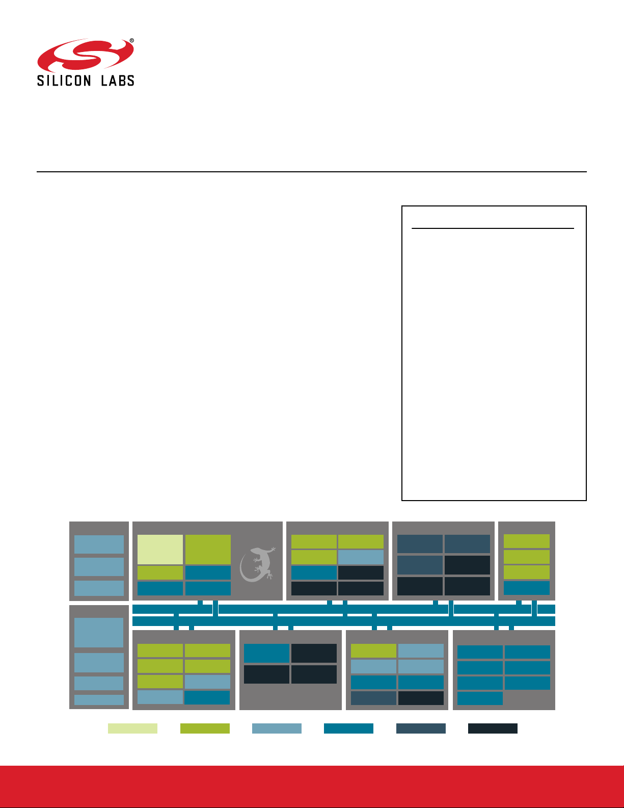
The WGM160P is an ultra low power all-inclusive Wi-Fi® module targeted for applications requiring excellent RF performance, low power consumption, high security, integrated customer applications and fast time to market.
The WGM160P module integrates all of the necessary elements required for a cloud
connected IoT Wi-Fi application, including 802.11b/g/n radio, integrated chip antenna,
certifications, microcontroller, Wi-Fi and IP stacks, HTTP server, and multiple protocols,
such as TCP and UDP. Co-existence with external 2.4GHz transceivers is supported.
WGM160P can be configured to concurrently act as a Wi-Fi client and a Wi-Fi access
point, which is ideal for user friendly device provisioning. WGM160P can natively host Capplications, removing the need for an external host controller. Alternatively, the Wi-Fi
Module can run in Network Co-Processor (NCP) mode, leaving the complexity of TCP/IP
networking to the module so that the customer’s own host controller can be fully dedicated to processing the customer application tasks. The WGM160P module has highly
flexible host and peripheral hardware interfaces for wide application use.
This module also supports Gecko OS, a comprehensive software suite designed to simplify your Wi-Fi, application, device management and cloud connectivity development
process.
KEY POINTS
• Available with integrated chip antenna or
an RF pin
• Antenna diversity supported via secondary
RF pin
• IEEE 802.11 b/g/n compliant
• TX power: +16 dBm
• RX sensitivity: -96 dBm
• CPU core: 32-bit ARM® Cortex-M4
• Flash memory: 2 MB
• RAM: 512 kB
• Concurrent mode: Wi-Fi AP and STA
• Ultra low power consumption
• Wi-Fi Alliance certified (pending)
• Modular certification
• CE, FCC, ISED
• Japan, KC (pending)
• End-to-end security
• Built-in 10/100 Ethernet Support
• Gecko OS support
• Size: 23.8 mm x 14.2 mm x 2.3 mm
Energy Management
Voltage
Regulator
DC-DC
Converter
Brown-Out
Detector
Low Energy
Sensor IF
Real Time Counter
Watchdog Timer
CRYOTIMER
EM4H - Hibernate
Power-On Reset
Backup Domain
Voltage/Temp
Monitor
Analog Interfaces
Low Energy LCD
Controller
VDAC
Analog
Comparator
Capacitive
Sensing
EM4S - Shutoff
Other
CRYPTO
CRC
True Random
Number Generator
SMU
ADC
Operational
Amplifier
IDAC
MPU
Core / Memory
TM
Debug Interface
LDMA
Controller
ETM
Certified Module
Antenna
Matching
Radio XTAL
ARM Cortex
M4 processor
with FPU and
Flash Program
Memory
RAM Memory
Wi-Fi Radio
2.4 GHz
Transciever
802.11 b/g/n
MODEM
Diversity Input
PTA support
Lowest power mode with peripheral operational:
EM0 - Active
silabs.com | Building a more connected world. Preliminary Rev. 0.3
This information applies to a product under development. Its characteristics and specifications are subject to change without notice.
Serial Interfaces
USART
10/100 Ethernet
CAN
LEUSB
(crystal free)
UART
Quad-SPI
Low Energy
TM
UART
2
I
C
EM1 - Sleep
External
Interrupts
Pin Reset
EM2 – Deep Sleep
Clock Management
High Frequency
Crystal Oscillator
PLL
Auxiliary High
Freq. RC Osc.
Low Frequency
XTAL + Oscillator
High Frequency
RC Oscillator
Universal HF RC
Oscillator
Ultra Low Freq.
RC Oscillator
Low Frequency
RC Oscillator
32-bit bus
Peripheral Reflex System
I/O Ports Timers and Triggers
General
Purpose I/O
Pin Wakeup
Low Energy Timer
Real Time Counter
EM3 - Stop
Timer/Counter
Pulse Counter
and Calendar

1. Key Features
The key features of the WGM160P module are listed below.
Radio Features
• Built-in Antenna (optional)
• TX Power: +16 dBm
• RX Sensitivity: -96 dBm
• Superior blocking performance
Wi-Fi Features
• 802.11: b/g/n
• Bit rate: up to 72.2 Mbps
• 802.11 Security: WPA2/WPA Personal
• STA (Station Mode)
• SoftAP (Soft Access Point Mode)
Electrical Characteristics
• Supply voltage: 3.0V to 3.6V
Environmental specifications
• Temperature range: -40°C to +85°C
Modular certification (pending)
• Wi-Fi Alliance
• CE, FCC, ISED, KC, Japan
• RoHS/REACH compliant
Dimensions
• L x W x H: 23.8 mm x 14.2 mm x 2.3 mm
WGM160P Wi-Fi® Module Data Sheet
MCU Features
•
ARM® Cortex-M4, 72MHz
• 512 kB RAM
• 2 MB Flash
Hardware Interfaces
• Host interface: UART/SPI/USB
• Peripheral interfaces
• 2 x USART (UART/SPI/I2S)
• QSPI with Execute In Place (XIP) support
• SD Card support (SPI)
• Capacitive Touch Sensing in all GPIOs
• LESENSE
• 10/100 Ethernet MAC with RMII interface
• USB device (2.0 Full speed)
•
I2C peripheral interfaces
• CAN
• Up to 31 x GPIO with interrupts
• 2 x 12-bit ADC
• 2 x 12-bit DAC
• Rich selection of timers, inc. Real-time counters
• Co-existence interface (PTA: 2, 3, 4 wire)
Key Features
silabs.com | Building a more connected world. Preliminary Rev. 0.3 | 2

2. Ordering Information
WGM160P Wi-Fi® Module Data Sheet
Ordering Information
Table 2.1. Ordering Information
Part Number Protocol Max TX
Power
WGM160PX22KGA2 Wi-Fi (802.11 b/g/n) 16 dBm 2048 / 512 Included Built-in Up to 31 Cut Tape
WGM160PX22KGA2R Wi-Fi (802.11 b/g/n) 16 dBm 2048 / 512 Included Built-in Up to 31 Reel
WGM160P022KGA2 Wi-Fi (802.11 b/g/n) 16 dBm 2048 / 512 None Built-in Up to 31 Cut Tape
WGM160P022KGA2R Wi-Fi (802.11 b/g/n) 16 dBm 2048 / 512 None Built-in Up to 31 Reel
WGM160PX22KGN2 Wi-Fi (802.11 b/g/n) 16 dBm 2048 / 512 Included External (RF Pin) Up to 31 Cut Tape
WGM160PX22KGN2R Wi-Fi (802.11 b/g/n) 16 dBm 2048 / 512 Included External (RF Pin) Up to 31 Reel
WGM160P022KGN2 Wi-Fi (802.11 b/g/n) 16 dBm 2048 / 512 None External (RF Pin) Up to 31 Cut Tape
WGM160P022KGN2R Wi-Fi (802.11 b/g/n) 16 dBm 2048 / 512 None External (RF Pin) Up to 31 Reel
Note:
1. WGM160P modules come pre-programmed with the Gecko OS Kernel. Devices ship with the debug interface locked. Devices may
be reprogrammed via serial or OTA DFU and preserve the device credentials. Unlocking the debug interface will result in loss of
pre-programmed firmware, including Gecko OS Kernel and device credentials.
2. SLWSTK6121A Wireless Starter Kit and SLWRB4321A Radio Board are available to start developing with WGM160P Wi-Fi modules.
3. Devices listed may be referred to by the product family name (WGM160P), model name (WGM160P22A / WGM160P22N) or the
full orderable part number throughout this document.
Flash/Ram
(kB)
LF XTAL Antenna GPIO Carrier
silabs.com | Building a more connected world. Preliminary Rev. 0.3 | 3

Table of Contents
1. Key Features ...............................2
2. Ordering Information ............................3
3. System Overview ..............................6
3.1 Introduction ...............................6
3.2 Wi-Fi Supported 2.4 GHz ISM Modulations, BW, and Channels .............6
4. Electrical Specifications ...........................7
4.1 Absolute Maximum Ratings..........................7
4.2 Operating Conditions ............................8
4.3 Power Consumption ............................8
4.4 Digital I/O Specifications...........................9
4.5 RF Transmitter General Characteristics .....................10
4.6 RF Receiver General Characteristics ......................11
4.7 Radiated Characteristics...........................11
4.8 Microcontroller Peripherals ..........................12
5. Typical Applications and Connections .....................13
5.1 RF Connections .............................13
5.1.1 Antenna Ports .............................13
5.1.2 Antenna Diversity ...........................13
5.2 Multi-Protocol Co-Existance .........................13
5.3 Example Schematic ............................13
6. Gecko OS Features ............................14
7. Pin Descriptions .............................15
7.1 WGM160P Device Pinout ..........................15
7.2 GPIO Functionality Table ..........................17
7.3 Alternate Functionality Overview ........................21
8. Package Specifications ..........................31
8.1 Package Outline .............................31
8.2 Recommended PCB Land Patterns .......................32
8.3 Package Marking .............................34
9. Soldering Recommendations ........................35
10. Tape and Reel Dimensions .........................36
11. Certifications ..............................37
11.1 Qualified External Antenna Types .......................37
11.2 CE .................................37
silabs.com
| Building a more connected world. Preliminary Rev. 0.3 | 4

11.3 FCC .................................38
11.4 ISED Canada ..............................39
11.5 Locating the Module Close to Human Body ....................41
12. Revision History............................. 42
silabs.com | Building a more connected world. Preliminary Rev. 0.3 | 5
WGM160P Wi-Fi® Module Data Sheet
System Overview
3. System Overview
3.1 Introduction
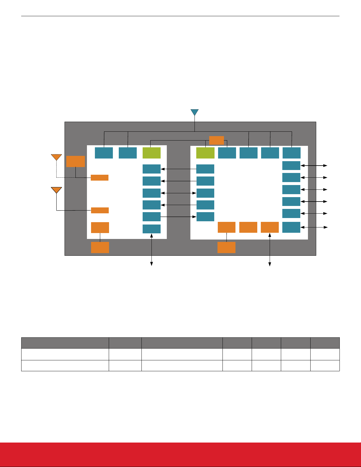
The WGM160P module combines the WF200 Wi-Fi transceiver with an EFM32GG11 microcontroller to deliver a complete and certified
standalone Wi-Fi solution, with the ability to run customer application on an Cortex M4 processor.
This device supports Gecko OS, a comprehensive software solution that simplifies the Wi-Fi , application and cloud connectivity development process to reduce time to market. For more details on the software platform, please consult our online documentation.
VBAT
3.0 – 3.6V
1.8V
4.7 µH
VDD
VDD
RESETN
WUP
HIF
LP_CLK
WIRQ
PTA
RF
DIG
RESETb
WUP
SDIO
32.768 kHz
WIRQ
DVDD V
GPIO
GPIO
SDIO
GPIO
GPIO
V
REGSW
LFXO
EFM32GG11
MCU Host
REGVDD
HFRCO
AVDD IOVDD
USB 2.0
ADC
DAC
GPIO
USART
QSPI
HFXO
ETH
RMII
External
Antenna
Chip
Antenna
VDD
RF1
RF2
HFXO
VDDIO
PA
WF200
WiFi NCP
802.11 B/G/N
RF XTAL
38.4M
LF XTAL
32.768K
Figure 3.1. WGM160P Block Diagram
3.2 Wi-Fi Supported 2.4 GHz ISM Modulations, BW, and Channels
Table 3.1. Supported Wi-Fi Modulations, BW, and Channels
Parameter Symbol Test Condition Min Typ Max Unit
Channel Center Frequency CHAN Subject to Regulatory Agency 2412 2437
2484
MHz
Channel Bandwidth BW — 20 — MHz
silabs.com | Building a more connected world. Preliminary Rev. 0.3 | 6

WGM160P Wi-Fi® Module Data Sheet
Electrical Specifications
4. Electrical Specifications
All electrical parameters in all tables are specified under the following conditions, unless stated otherwise:
• Typical values are based on T
• Radio performance numbers are measured in conducted mode, based on Silicon Laboratories reference designs using output power-specific external RF impedance-matching networks for interfacing to a 50 Ω antenna port. Conducted RF measurements include
additional output power reductions to guarantee WiFi and regulatory emissions compliance while connected to the specified antennas which have non-ideal impedance loading.
Refer to Section 4.2 Operating Conditions for more details about operational supply and temperature limits.
4.1 Absolute Maximum Ratings
Stresses above those listed below may cause permanent damage to the device. This is a stress rating only and functional operation of
the devices at those or any other conditions above those indicated in the operation listings of this specification is not implied. Exposure
to maximum rating conditions for extended periods may affect device reliability. For more information on the available quality and reliability data, see the Quality and Reliability Monitor Report at http://www.silabs.com/support/quality/pages/default.aspx.
Parameter Symbol Test Condition Min Typ Max Unit
= 25 °C; V
AMB
= 3.3V; Center Frequency = 2,437 MHz.
VBAT
Table 4.1. Absolute Maximum Ratings
Storage temperature T
RF power level at RF1 and
RF2 ports
STG
P
RFMAX
Max power that can be applied to
input of recommended matching
-40 — 105 °C
— — 10 dBm
network connected to RF1 and
RF2 pins.
Maximum supply voltage to
VBAT
MAX
-0.3 — 3.6 V
VBAT
DC voltage on I/O pins VG
MAX
5 V tolerant GPIO (PF0, PF1,
PF10, PF11)1
2
-0.3 — Min of 5.25
and VBAT
+2
All other GPIO and PTA pins -0.3 — VBAT + 0.3 V
Current into any GPIO pin IO
Sum of current into all GPIO
IO
MAX
ALLMAX
— — 20 mA
— — 150 mA
pins
Range of load impedance at
LOAD
TX
— — 10:1 VSWR
RF1 and RF2 pins during TX
Note:
1. When a GPIO is used for analog functions via the APORT, the maximum voltage is VBAT.
2. To operate above the VBAT supply rail, over-voltage tolerance must be enabled according to the GPIO_Px_OVTDIS register.
Pins with over-voltage tolerance disabled have the same limits as all other GPIO (max = VBAT + 0.3 V).
V
silabs.com | Building a more connected world. Preliminary Rev. 0.3 | 7

WGM160P Wi-Fi® Module Data Sheet
Electrical Specifications
4.2 Operating Conditions
Table 4.2. Recommended Operating Conditions
Parameter Symbol Test Condition Min Typ Max Unit
Ambient operating tempera-
TA
OP
-40 — 85 °C
ture
Nominal supply voltage to
1
VBAT
V
VBAT
3.0 3.3 3.6 V
Note:
1. Operating outside of the recommended voltage supply range is not supported. The module may disable WiFi transmit functions
when operating outside of this range in order to guarantee regulatory emissions compliance.
4.3 Power Consumption
All currents measured with VBAT = 3.3 V.
Table 4.3. Power Consumption
Parameter Symbol Test Condition Min Typ Max Unit
Continuous TX current, 1
ITX
MAX
— 141.3 — mA
Mbps, max power setting
Continuous TX current,
ITX
MAX_N
— 131.4 — mA
MCS7, max power setting
Continuous RX listen current IRX
MAX
— 36.6 — mA
Continuous RX receive current, 1 Mbps
Continuous RX receive current, MCS7
Idle associated current,
DTIM=1
Idle associated current,
DTIM=3
Idle associated current,
DTIM=10
Sleep mode current I
Idle current average I
IRX
MAXR
IRX
MAXR_N
I
DTIM1
I
DTIM3
I
DTIM10
SLEEP
IDLE
— 34.5 — mA
— 38.5 — mA
UART off — TBD — mA
UART off — TBD — mA
UART off — TBD — mA
— TBD — mA
— TBD — mA
silabs.com | Building a more connected world. Preliminary Rev. 0.3 | 8

WGM160P Wi-Fi® Module Data Sheet
Electrical Specifications
4.4 Digital I/O Specifications
Table 4.4. Digital I/O Specifications
Parameter Symbol Test Condition Min Typ Max Unit
Voltage input high (relative to
VBAT)
Voltage input low (relative to
VBAT)
Logic low output voltage (relative to VBAT)
Logic high output voltage
(relative to VBAT)
Input leakage current I
Pullup resistance R
Pulldown resistance R
Output fall time from VOH to
V
OL
V
V
V
V
Leak
T
IH
IL
OL
OH
PU
PD
OF
70 — — %
— — 30 %
PTA Pins, Sinking 5 mA — — 25 %
GPIO Pins, Sinking 20 mA, DRIV-
— — 20 %
ESTRENGTH = STRONG
PTA Pins, Sourcing 5 mA 80 — — %
GPIO Pins, Sourcing 20 mA,
80 — — %
DRIVESTRENGTH = STRONG
All I/O when GPIO voltage ≤
— 1 — nA
VBAT
5 V Tolerant I/O (PF0, PF1, PF10,
— 3.3 15 µA
PF11) when VBAT < GPIO voltage ≤ VBAT + 2 V
30 43 65 kΩ
30 43 65 kΩ
50 pF load — 15 TBD ns
Output rise time from VOL to
V
OH
Required external series resistor on USB D+ and D-
T
R
OR
USB
50 pF load — 15 TBD ns
— 33 +/-10% — Ω
silabs.com | Building a more connected world. Preliminary Rev. 0.3 | 9

WGM160P Wi-Fi® Module Data Sheet
Electrical Specifications
4.5 RF Transmitter General Characteristics
Unless otherwise indicated, typical conditions are: Operating Ambient Temp = 25 °C, VBAT = 3.3 V, center frequency = 2,437 MHz,
and measured in 50 Ω test equipment attached at antenna port.
Measurements for this specification are made at the 50 Ω Antenna Port. See Section 5.1.1 Antenna Ports. Conducted RF measurements include additional output power reductions to guarantee WiFi and regulatory emissions compliance while connected to the specified antennas which have non-ideal impedance loading.
Table 4.5. RF Transmitter Characteristics
Parameter Symbol Test Condition Min Typ Max Unit
Maximum RMS Output Power at Antenna (High Power
2
PA)1
POUT
HPPA
MAX_RMS_
802.11b: 1 Mbps — 16.1 — dBm
802.11b: 11 Mbps — 15.1 — dBm
802.11g: 6 Mbps — 14.7 — dBm
802.11g: 54 Mbps — 9.1 — dBm
802.11n: MCS=0 — 14.4 — dBm
802.11n: MCS=7 — 5.8 — dBm
Carrier frequency error CARR
ROR
POUT variation over supply
POUT
FREQ_ER-
VAR_V
Across temperature -25 — 25 ppm
VBAT = 3.0-3.6 V — +0.3 / -1.1 — dB
voltage range, relative to
nominal 3.3 V
POUT variation over fre-
POUT
VAR_F
CH1 to CH14 — +/-0.15 — dB
quency range, relative to
average
POUT variation over temper-
2
POUT
VAR_T
-40 to +85C — +0.1 / -1.2 — dB
ature range, relative to 25C
Note:
1. VBAT should be at least 3.0 V to achieve the rated RF transmitter output power levels.
2. Rated power levels may not apply to the edge channels, which may need additional backoff for FCC compliance.
silabs.com | Building a more connected world. Preliminary Rev. 0.3 | 10

WGM160P Wi-Fi® Module Data Sheet
Electrical Specifications
4.6 RF Receiver General Characteristics
Unless otherwise indicated, typical conditions are: Operating Ambient Temp = 25 °C, VBAT = 3.3 V, center frequency = 2,437 MHz,
and measured in 50 Ω test equipment attached at antenna port.
Measurements for this specification are made at the 50 Ω Antenna Port. See Section 5.1.1 Antenna Ports.
Table 4.6. RF Receiver Characteristics
Parameter Symbol Test Condition Min Typ Max Unit
RX Sensitivity for 8% FER
(1024 Octet)
RX Sensitivity for 10% PER
(1024 Octet)
RX Sensitivity for 10% PER
(4096 Octet)
RX Max Strong Signal for
8% FER (1024 Octet)
RX Max Strong Signal for
10% PER (1024 Octet)
RX Max Strong Signal for
10% PER (4096 Octet)
Sensitivity variation across
frequency range, CH1 to
CH14
Sensitivity variation over
temperature range, -40 to
85C
SENS
SENS
SENSE
RX
SAT_B
RX
SAT_G
RX
SAT_N
SENS
SENS
B
G
N
VAR_V
VAR_TEMP
802.11b: 1 Mbps — -96.4 — dBm
802.11b: 11 Mbps — TBD — dBm
802.11g: 6 Mbps — TBD — dBm
802.11g: 54 Mbps — TBD — dBm
802.11n: MCS=0 — TBD — dBm
802.11n: MCS=7 — TBD — dBm
802.11b: 1 Mbps — -4.0 — dBm
802.11b: 11 Mbps — -10.0 — dBm
802.11g: 6 Mbps — -9.0 — dBm
802.11g: 54 Mbps — -9.0 — dBm
802.11n: MCS=0 — -9.0 — dBm
802.11n: MCS=7 — -9.0 — dBm
802.11b 1 Mbps — +/-0.5 — dB
802.11b 1 Mbps — +/-1.3 — dB
RX Channel power Indicator
RCPI
STEP
802.11b: 1 Mbps — 0.5 — dBm
Step Size
4.7 Radiated Characteristics
Unless otherwise indicated, typical conditions are: Operating Ambient Temp = 25 °C, VBAT = 3.3 V, center frequency = 2437 MHz,
using the integrated antenna, and measured with the ideal application board size for 2.4 GHz radiation.
Table 4.7. Radiated Characteristics
Parameter Symbol Test Condition Min Typ Max Unit
Application board size, radiated edge "X" dimension
Antenna Efficiency ANT
PCB
1
X_MM
EFF
Optimal application board design — -1.4 — dB
35 50 — mm
Note:
1. Refer to "UG384: WGM160P Hardware Design Users Guide" for more PCB layout details.
silabs.com | Building a more connected world. Preliminary Rev. 0.3 | 11

WGM160P Wi-Fi® Module Data Sheet
Electrical Specifications
4.8 Microcontroller Peripherals
WGM160P offers an extensive list of peripherals, some of which are listed below:
• 12-bit ADC
• 12-bit DAC
• GPIO
• USART (UART/SPI/I2S)
• QSPI with Execute In Place (XIP) support
• Capacitive Touch Sensing in all GPIOs
• LESENSE
• 10/100 Ethernet MAC with RMII interface (50 MHz external crystal required)
• USB device (2.0 Full speed)
•
I2C peripheral interfaces
• CAN
• Timers
• LCD Driver
For more information on the pins these peripherals are availabile on, please consult: 7.2 GPIO Functionality Table and 7.3 Alternate
Functionality Overview.
For details on the electrical performance of these peripherals, please consult the relevant portions of Section 4 in the EFM32GG11
Family Datasheet.
silabs.com | Building a more connected world. Preliminary Rev. 0.3 | 12
WGM160P Wi-Fi® Module Data Sheet
Typical Applications and Connections
5. Typical Applications and Connections
5.1 RF Connections
5.1.1 Antenna Ports
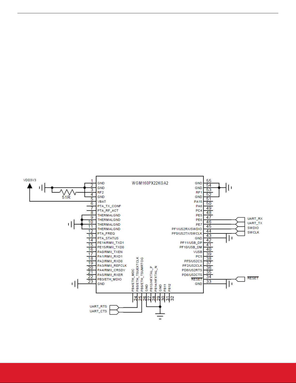
The WGM160P offers two RF ports that support antenna diversity using an internal switch. In applications with only one antenna, the
unused port should be terminated to ground with a 47-51 Ω resistor. Leaving the unused port floating or tying directly to ground will
result in degraded performance. An external antenna connected to either RF port needs to be properly matched with at least -10dB
return loss (VSWR < 2).
5.1.2 Antenna Diversity
In applications where multipath fading is a potential issue, such as indoors, a second antenna can be connected. A firmware feature
can be enabled to automatically determine which of the two antennas gives a better signal, allowing significant improvement in link reliability.
5.2 Multi-Protocol Co-Existance
Packet Transmit Arbitration (PTA) pins are provide to share antenna and optimize co-existence performance with other networks including other protocols. See Application Notes "AN1128 Bluetooth Coexistance with Wi-Fi" and "AN1017 Zigbee and Thread Coexistance
with Wi-Fi" for more information.
5.3 Example Schematic
Figure 5.1. Example Schematic for NCP Application
silabs.com | Building a more connected world. Preliminary Rev. 0.3 | 13

WGM160P Wi-Fi® Module Data Sheet
Gecko OS Features
6. Gecko OS Features
The Gecko OS software supplied with the WGM160P provides a wide range of features beyond the underlying hardware, and supports
application development via its command API.
For complete documentation of Gecko OS, see https://docs.silabs.com/gecko-os/.
Software APIs
• Gecko OS Command API
• Gecko OS Native C API
Interfaces
• Serial (UART, remote terminal)
• SoftAP and WLAN client (concurrent)
• I2C master
• SPI master
Servers
• TCP/TLS, UDP, HTTP(S), DHCP, DNS
• HTTP(S) Server with RESTful API and Websockets
Clients
• TCP/TLS, UDP, NTP, Secure-SMTP, DHCP, DNS
• HTTP(S) client
• Websocket client
Setup
• Multiple Wi-Fi setup options, including via serial command and
Web setup with SoftAP
Peripherals and Sensors
• GPIOs for control, indication and monitoring
• I2C-master API for interfacing to external peripherals
• SPI-master API for interfacing to external peripherals
• Automated broadcast and streaming of sensor data
• Local caching of sensor data
Update and Recovery
• Wireless OTA (Over-the-Air) update to remote manage firmware using the Zentri DMS (Device Management Service)
System Management
• System configuration and monitoring via setting and getting a
wide range of variables
• Configurable power states
• Sleep/wake timers
File System
• Read/write file system with appendable log files
• Storage of large files
• Optional additional bulk serial flash
• HTTP download to file system, HTTP upload from file system
silabs.com | Building a more connected world. Preliminary Rev. 0.3 | 14
7. Pin Descriptions
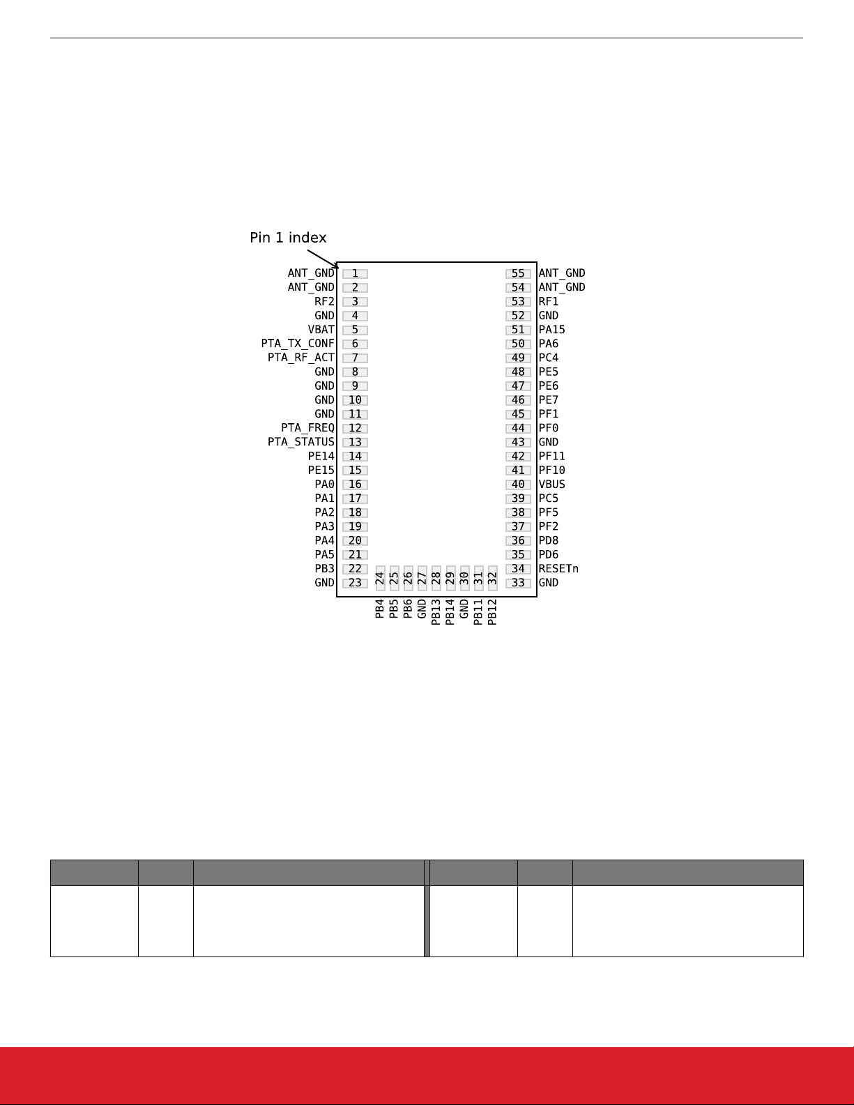
7.1 WGM160P Device Pinout
WGM160P Wi-Fi® Module Data Sheet
Pin Descriptions
Figure 7.1. WGM160P Device Pinout
The following table provides package pin connections and general descriptions of pin functionality. For detailed information on the supported features for each GPIO pin, see 7.2 GPIO Functionality Table or 7.3 Alternate Functionality Overview.
Table 7.1. WGM160P Device Pinout
Pin Name Pin(s) Description Pin Name Pin(s) Description
1
ANT_GND
silabs.com | Building a more connected world. Preliminary Rev. 0.3 | 15
2
Antenna ground. RF2 3
54
55
External antenna connection for diversity antenna. Terminate to ground with
47-51 Ohms if not connected to an antenna.

WGM160P Wi-Fi® Module Data Sheet
Pin Name Pin(s) Description Pin Name Pin(s) Description
4
8
9
10
11
Ground. Connect all ground pins to
GND
23
27
ground plane.
VBAT 5 Module power supply
30
33
43
52
Pin Descriptions
PTA_TX_CO
NF
PTA_FREQ 12
PTA TX_CONF pin. These pins can be
6
used to manage co-existence with another 2.4 GHz radio.
PTA FREQ pin. These pins can be
used to manage co-existence with another 2.4 GHz radio.
PTA_RF_AC
T
PTA_STA-
TUS
7
13
PE14 14 GPIO PE15 15 GPIO
PA0 16 GPIO PA1 17 GPIO
PA2 18 GPIO PA3 19 GPIO
PA4 20 GPIO PA5 21 GPIO
PB3 22 GPIO PB4 24 GPIO
PB5 25 GPIO PB6 26 GPIO
PB13 28 GPIO PB14 29 GPIO
PB11 31 GPIO PB12 32 GPIO
Reset input, active low. This pin is internally pulled up to VBAT. To apply an
RESETn 34
external reset source to this pin, it is required to only drive this pin low during
PD6 35 GPIO
reset, and let the internal pull-up ensure
that reset is released.
PTA RF_ACT pin. These pins can be
used to manage co-existence with another 2.4 GHz radio.
PTA STATUS pin. These pins can be
used to manage co-existence with another 2.4 GHz radio.
PD8 36 GPIO PF2 37 GPIO
PF5 38 GPIO PC5 39 GPIO
USB VBUS signal and auxiliary input to
VBUS 40
5 V regulator. May be left disconnected
PF10 41 GPIO (5V)
if USB is unused.
PF11 42 GPIO (5V) PF0 44 GPIO (5V)
PF1 45 GPIO (5V) PE7 46 GPIO
PE6 47 GPIO PE5 48 GPIO
PC4 49 GPIO PA6 50 GPIO
External antenna connection on
PA15 51 GPIO RF1 53
WGM160P22N. Not connected on
WGM160P22A.
Note:
1. GPIO with 5V tolerance are indicated by (5V).
silabs.com | Building a more connected world. Preliminary Rev. 0.3 | 16

WGM160P Wi-Fi® Module Data Sheet
Pin Descriptions
7.2 GPIO Functionality Table
A wide selection of alternate functionality is available for multiplexing to various pins. The following table shows the name of each GPIO
pin, followed by the functionality available on that pin. Refer to 7.3 Alternate Functionality Overview for a list of GPIO locations available
for each function.
Full peripheral features and flexibility are not supported with all software architectures. In particular, some restrictions apply when using
Gecko OS. Refer to “UG384 WGM160P Hardware Design Users Guide” for more details.
Table 7.2. GPIO Functionality Table
GPIO Name Pin Alternate Functionality / Description
Analog Timers Communication Other
ETH_RMIITXEN
PA0
PA1
PA2
PA3
BUSBY
BUSAX
LCD_SEG13
BUSAY
BUSBX
LCD_SEG14
BUSBY
BUSAX
LCD_SEG15
BUSAY
BUSBX
LCD_SEG16
TIM0_CC0 #0
TIM0_CC1 #7
TIM3_CC0 #4
PCNT0_S0IN #4
TIM0_CC0 #7
TIM0_CC1 #0
TIM3_CC1 #4
PCNT0_S1IN #4
TIM0_CC2 #0
TIM3_CC2 #4
TIM0_CDTI0
TIM3_CC0 #5
US1_RX #5
US3_TX #0
QSPI0_CS0
LEU0_RX #4
I2C0_SDA #0
ETH_RMIIRXD1
US3_RX #0
QSPI0_CS1
I2C0_SCL #0
ETH_RMIIRXD0
US1_RX #6
US3_CLK
QSPI0_DQ0
ETH_RMIIREFCLK
US3_CS
U0_TX #2
QSPI0_DQ1
CMU_CLK2 #0
PRS_CH0 #0
PRS_CH3
GPIO_EM4WU0
CMU_CLK1 #0
PRS_CH1
CMU_CLK0 #0
PRS_CH8
ETM_TD0 #3
CMU_CLK2 #1
CMU_CLKI0 #1
CMU_CLK2 #4
LES_ALTEX2
PRS_CH9
ETM_TD1
ETH_RMIICRSDV
PA4
BUSBY
BUSAX
LCD_SEG17
TIM0_CDTI1
TIM3_CC1 #5
US3_CTS #0
U0_RX #2
LES_ALTEX3
PRS_CH16 #0
ETM_TD2 #3
QSPI0_DQ2
ETH_RMIIRXER
LES_ALTEX4
BUSAY
TIM0_CDTI2 #0
US3_RTS
PRS_CH17 #0
PA5
BUSBX
TIM3_CC2 #5
U0_CTS
ACMP1_O #7
LCD_SEG18
PCNT1_S0IN #0
QSPI0_DQ3
ETM_TD3 #3
LEU1_TX #1
silabs.com | Building a more connected world. Preliminary Rev. 0.3 | 17

GPIO Name Pin Alternate Functionality / Description
Analog Timers Communication Other
WGM160P Wi-Fi® Module Data Sheet
Pin Descriptions
PA6
PA15
PB3
PB4
PB5
BUSBY
BUSAX
LCD_SEG19
BUSAY
BUSBX
LCD_SEG12
BUSAY
BUSBX
LCD_SEG20 /
LCD_COM4
BUSBY
BUSAX
LCD_SEG21 /
LCD_COM5
BUSAY
BUSBX
LCD_SEG22 /
LCD_COM6
TIM3_CC0 #6
WTIM0_CC0 #1
LETIM1_OUT1 #0
PCNT1_S1IN #0
TIM3_CC2 #0
TIM1_CC3 #2
WTIM0_CC0 #6
PCNT1_S0IN #1
WTIM0_CC1 #6
PCNT1_S1IN #1
WTIM0_CC2 #6
LETIM1_OUT0
PCNT0_S0IN #6
ETH_MDC #3
U0_RTS #2
LEU1_RX #1
ETH_MDIO #3
US2_CLK #3
ETH_MDIO #0
US2_TX #1
US3_TX #2
QSPI0_DQ4
ETH_MDC #0
US2_RX #1
QSPI0_DQ5
LEU1_TX #4
ETH_TSUEXTCLK
US0_RTS #4
US2_CLK #1
QSPI0_DQ6
LEU1_RX #4
PRS_CH6 #0
ACMP0_O #4
ETM_TCLK
GPIO_EM4WU1
PRS_CH15 #0
PRS_CH19 #0
ACMP0_O #7
PRS_CH20
PRS_CH21 #0
PB6
PB11
PB12
BUSBY
BUSAX
LCD_SEG23 /
LCD_COM7
BUSAY
BUSBX
VDAC0_OUT0 /
OPA0_OUT
IDAC0_OUT
BUSBY
BUSAX
VDAC0_OUT1 /
OPA1_OUT
TIM0_CC0 #3
TIM2_CC0 #4
WTIM3_CC0
LETIM1_OUT1 #4
PCNT0_S1IN #6
TIM0_CDTI2 #4
TIM1_CC2
WTIM2_CC2
LETIM0_OUT0 #1
PCNT0_S1IN #7
PCNT1_S0IN #6
TIM1_CC3 #3
WTIM2_CC0
LETIM0_OUT1 #1
PCNT0_S0IN #7
PCNT1_S1IN #6
ETH_TSUTMRTOG
US0_CTS #4
US2_CS #1
QSPI0_DQ7
US0_CTS #5
US1_CLK #5
US2_CS #3
U1_CTS #2
I2C1_SDA #1
US2_CTS #1
U1_RTS #2
I2C1_SCL #1
PRS_CH12 #1
CMU_CLK1 #5
CMU_CLKI0 #7
PRS_CH21 #2
ACMP0_O #3
GPIO_EM4WU7
PRS_CH16 #1
silabs.com | Building a more connected world. Preliminary Rev. 0.3 | 18

GPIO Name Pin Alternate Functionality / Description
Analog Timers Communication Other
WGM160P Wi-Fi® Module Data Sheet
Pin Descriptions
PB13
PB14
PC4
PC5
PD6
BUSAY
BUSBX
HFXTAL_P
BUSBY
BUSAX
HFXTAL_N
BUSACMP0Y
BUSACMP0X
OPA0_P
BUSACMP0Y
BUSACMP0X
OPA0_N
BUSADC0Y
BUSADC0X
ADC0_EXTP
VDAC0_EXT
ADC1_EXTP
OPA1_P
TIM6_CC0
WTIM1_CC0 #0
PCNT2_S0IN #2
TIM6_CC1
WTIM1_CC1
PCNT2_S1IN #2
TIM0_CC0 #5
TIM0_CDTI2 #3
TIM2_CC2
LETIM0_OUT0 #3
PCNT1_S0IN #3
TIM0_CC1 #5
LETIM0_OUT1 #3
PCNT1_S1IN #3
TIM1_CC0 #4
TIM6_CC2
WTIM0_CDTI2
WTIM1_CC0 #2
LETIM0_OUT0 #0
PCNT0_S0IN #3
US0_CLK #4
US1_CTS
LEU0_TX #1
US0_CS
US1_RTS
LEU0_RX #1
US2_CLK #0
U0_TX #4
U1_CTS #4
I2C1_SDA #0
US2_CS #0
U0_RX #4
U1_RTS #4
I2C1_SCL #0
US0_RTS #5
US1_RX #2
US2_CTS #5
US3_CTS #2
U0_RTS #5
I2C0_SDA #1
CMU_CLKI0 #3
PRS_CH7 #0
PRS_CH6 #1
LES_CH4
PRS_CH18
GPIO_EM4WU6
LES_CH5
PRS_CH19 #2
CMU_CLK2 #2
LES_ALTEX0
PRS_CH5
ACMP0_O #2
ETM_TD0 #0
CMU_CLK1 #1
PD8 BU_VIN WTIM1_CC2 #2 US2_RTS
PRS_CH12 #2
ACMP2_O
TIM3_CC0 #3
US0_CLK #1
TIM3_CC2 #2
BUSCY
US1_CLK #6
TIM5_CC1 #0
PE5
BUSDX
US3_CTS #1
PRS_CH17 #2
TIM6_CDTI1
LCD_COM1
U1_RTS #3
WTIM0_CC1 #0
I2C0_SCL #7
WTIM1_CC2 #4
TIM3_CC1 #3
BUSDY
TIM5_CC2 #0
US0_RX
PE6
BUSCX
TIM6_CDTI2
PRS_CH6 #2
US3_TX #1
LCD_COM2
WTIM0_CC2 #0
WTIM1_CC3
silabs.com | Building a more connected world. Preliminary Rev. 0.3 | 19
 Loading...