

Alberga Business Park, Bertel Jungin aukio 3
FI-02600 Espoo, Finland
Phone: +358 9 435 5060
www.silabs.com
MGM210L Installation Guide
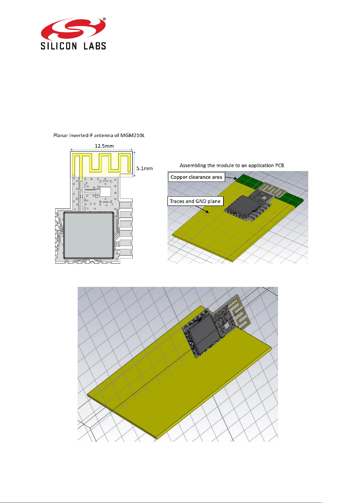
Figure 1 is showing the optimal installation of MGM210L to an application PCB. The size and
shape of the application PCB has an impact to the radiation patterns and radiation efficiency
of the antenna. An optional installation is shown in Figure 2. Metal objects in close proximity
of the antenna will have negative impact to the radiation efficiency.
Figure 1: Installing the module to an application PCB
Figure 2: Optional installation to an application PCB
Page 2 of 6
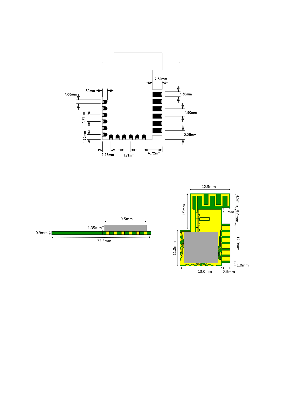
Figure 3:MGM210L footprint
Figure 4: MGM210L external dimensions
1
18
12

Page 3 of 6
Figure 5: MGM210L pinout
Figure 6: Recommended PCB Land Pattern
FCC
This device complies with Part 15 of the FCC Rules. Operation is subject to the following two
conditions:
PA01
PA02
PA03
PA04
1.2V
GND
1
2
3
4
5
6
7 PC00
8 PC0
1
9 PD0
1
10
PD0
0
11
Rese
t
12
GND
VDD
13
GND
14
PC05
PC04
PC03
PC02
15
16
17
18

Page 4 of 6
(1) this device may not cause harmful interference, and
(2) this device must accept any interference received, including interference that may cause
undesired operation.
Any changes or modifications not expressly approved by Silicon Labs could void the user’s authority to
operate the equipment.
FCC RF Radiation Exposure Statement:
This equipment complies with FCC radiation exposure limits set forth for an uncontrolled
environment. End users must follow the specific operating instructions for satisfying RF
exposure compliance. This transmitter meets both portable and mobile limits as
demonstrated in the RF Exposure Analysis. This transmitter must not be co-located or
operating in conjunction with any other antenna or transmitter except in accordance with
FCC multi-transmitter product procedures.
OEM Responsibilities to comply with FCC Regulations
OEM integrator is responsible for testing their end-product for any additional compliance
requirements required with this module installed (for example, digital device emissions, PC
peripheral requirements, etc.).
• The antenna(s) must be installed such that a minimum separation distance of 12 mm
is maintained between the radiator (antenna) and all persons at all times.
• The transmitter module must not be co-located or operating in conjunction with any
other antenna or transmitter except in accordance with FCC multi-transmitter product
procedures.
IMPORTANT NOTE: In the event that the above conditions cannot be met (for certain
configurations or co-location with another transmitter), then the FCC authorization is no
longer considered valid and the FCC ID cannot be used on the final product. In these
circumstances, the OEM integrator will be responsible for re-evaluating the end product
(including the transmitter) and obtaining a separate FCC authorization.
End Product Labeling
The module is labeled with its own FCC ID. If the FCC ID is not visible when the module is
installed inside another device, then the outside of the device into which the module is
installed must also display a label referring to the enclosed module. In that case, the final
product must be labeled in a visible area with the following:
“Contains Transmitter Module FCC ID: QOQMGM210L”
or
“Contains FCC ID: QOQMGM210L”
The OEM integrator has to be aware not to provide information to the end user regarding
how to install or remove this RF module or change RF related parameters in the user
manual of the end product.

Page 5 of 6
ISED Canada
This radio transmitter (IC: 5123A-MGM210L) has been approved by Industry Canada to
operate with the embedded antenna. Any other antenna types are strictly prohibited for use
with this device
This device complies with Industry Canada’s license-exempt RSS standards. Operation is
subject to the following two conditions:
(1) This device may not cause interference; and
(2) This device must accept any interference, including interference that may cause
undesired operation of the device
RF Exposure Statement
Exception from routine SAR evaluation limits are given in RSS-102 Issue 5.
The module meets the given requirements when the minimum separation distance to human
body is 20 mm.
RF exposure or SAR evaluation is not required when the separation distance is same or
more than stated above. If the separation distance is less than stated above the OEM
integrator is responsible for evaluating the SAR.
OEM Responsibilities to comply with IC Regulations
The module has been certified for integration into products only by OEM integrators under
the following conditions:
• The antenna must be installed such that a minimum separation distance as stated
above is maintained between the radiator (antenna) and all persons at all times.
• The transmitter module must not be co-located or operating in conjunction with any
other antenna or transmitter.
As long as the two conditions above are met, further transmitter testing will not be required.
However, the OEM integrator is still responsible for testing their end-product for any
additional compliance requirements required with this module installed (for example, digital
device emissions, PC peripheral requirements, etc.).
IMPORTANT NOTE: In the event that these conditions cannot be met (for certain
configurations or co-location with another transmitter), then the ISEDC authorization is no
longer considered valid and the IC ID cannot be used on the final product. In these
circumstances, the OEM integrator will be responsible for re-evaluating the end product
(including the transmitter) and obtaining a separate ISEDC authorization.
End Product Labeling
The module is labeled with its own IC ID. If the IC ID is not visible when the module is
installed inside another device, then the outside of the device into which the module is
installed must also display a label referring to the enclosed module. In that case, the final
end product must be labeled in a visible area with the following:
“Contains Transmitter Module IC: 5123A-MGM210L”

Page 6 of 6
or
“Contains IC: 5123A-MGM210L
The OEM integrator has to be aware not to provide information to the end user regarding
how to install or remove this RF module or change RF related parameters in the user
manual of the end product
 Loading...