

Silicon Laboratories Finland MGM13P User Manual
Alberga Business Park, Bertel Jungin aukio 3
FI-02600 Espoo, Finland
Phone: +358 9 435 5060
www.silabs.com
INSTALLATION GUIDE
Page 2 of 6
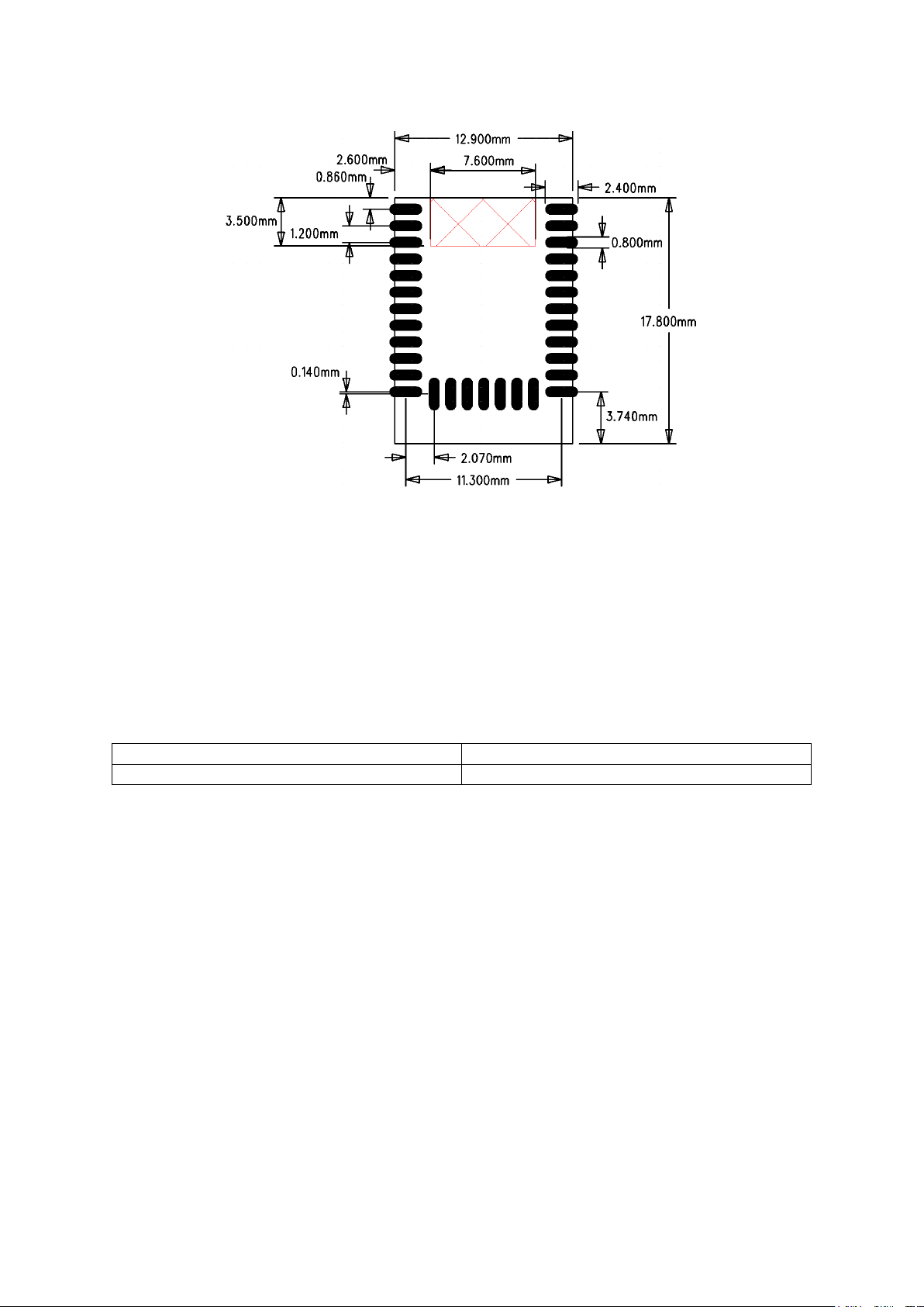
Figure 9.4: Recommended PCB Land Pattern
Qualified Antenna Types
This device has been designed to operate with a standard 2.14 dBi dipole antenna. Any
antenna of a different type or with a gain higher than 2.14 dBi is strictly prohibited for use
with this device. Using an antenna of a different type or gain more than 2.14 dBi will require
additional testing for FCC, CE and IC. The required antenna impedance is 50 Ω.
Antenna type
Maximum gain
Dipole
2.14 dBi
Table 1: Qualified antennas for MGM12Px
CE
The MGM13P02 modules are in conformity with the essential requirements and other
relevant requirements of the Radio Equipment Directive(RED). Please note that every
application using the MGM12P will need to perform the radio EMC tests on the end product
according toEN 301 489-17. Separate RF testing is not required provided that the customer
follows the module manufacturer's recommendations and instructions and does not make
modifications e.g. to the provided antenna solutions or requirements. A formal DoC is
available via www.silabs.com
MGM13P12 module is in conformity with the essential requirements and other relevant
requirements of the Radio Equipment Directive(RED) at nominal 10 dBm transmit power.
The transmit power of the module is not limited and when an end product is using
MGM13P12, the end product manufacturer is responsible that the end product is in
inconformity of all relevant requirements of the RED.
 Loading...