

Blue Gecko BGM111 Bluetooth® Smart
Module Data Sheet
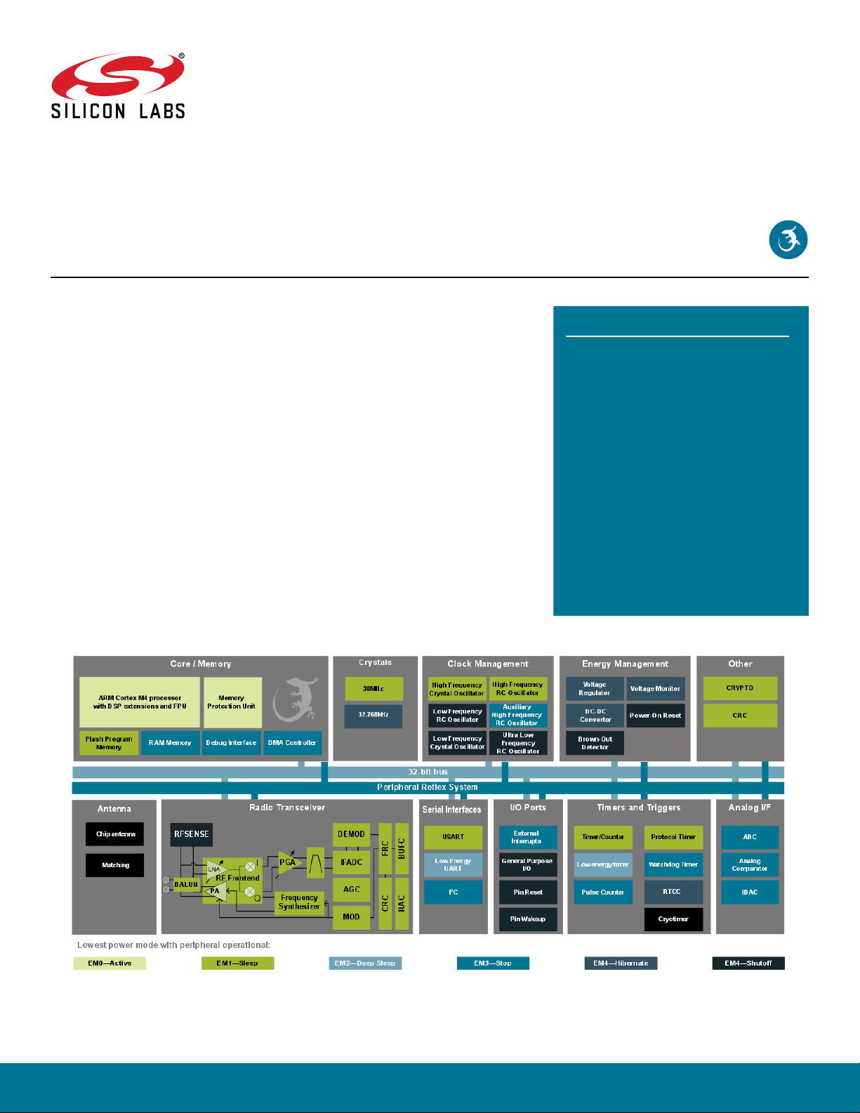
The BGM111 is a Bluetooth® Smart module targeted for Bluetooth Smart applications
where good RF performance, low power consumption and easy application development
are key requirements. At +8 dBm TX power BGM111 has best-in-class RF performance
and can provide long range, robust Bluetooth Smart connectivity.
The BGM111 integrates all of the necessary elements required for a Bluetooth Smart
application: Bluetooth radio, software stack and GATT based profiles and it can also
host end user applications, which means no external microcontroller is required in size,
price or power constrained devices. The BGM111 Bluetooth Smart module also has
highly flexible hardware interfaces to connect to different peripherals or sensors.
Although the BGM111 Bluetooth Smart Module is targeted at applications requiring high
RF performance, it still has ultra-low power consumption and can be operated using a
standard 3V coin cell battery.
BGM111 can be used in a wide variety of applications:
• Health and Fitness
• Point-of-Sales
• Consumer Electronics
• Automotive Aftermarket
• Industrial and Home Automation
• Others
KEY FEATURES
• Bluetooth 4.1 Compliant (Bluetooth Smart)
• Software upgradable to Bluetooth 4.2
• TX power: up to +8 dBm
• RX sensitivity: down to -92 dBm
• Range: up to 200 meters
•
CPU core: 32-bit ARM® Cortex-M4
• Flash memory: 256 kB
• RAM: 32 kB
• Autonomous Hardware Crypto Accelerator
and True Random Number Generator
• Integrated DC-DC Converter
silabs.com | Smart. Connected. Energy-friendly. Rev. 0.96

1. Feature List
The highlighted features are listed below.
Bluetooth Features
Blue Gecko BGM111 Bluetooth® Smart Module Data Sheet
Feature List
Harware Interfaces
• Bluetooth 4.1 Compliant
• Software Upgradable to Bluetooth 4.2
• Central and Peripheral Roles
• Up to 6 x BLE Connections in Central Role
Radio Features
• Integrated Antenna
• TX Power (+8 dBm)
• RX Sensitivity (-92 dBm)
• Up to 200 meters LoS range
Software Features
• Integrated Bluetooth Smart Stack
• Any GATT based Bluetooth Smart Profile
• 100 kbps throughput over BLE
•
BGAPI™ serial protocol over UART for modem (NCP) usage
•
BGLIB™ host library which implements BGAPI serial protocol
•
BGScript™ script and C programming for standalone usage
•
Profile Toolkit™ for creating GATT based services
• UART host interface
• 2 x SPI, UART and 2 x I2C peripheral interfaces
• Up to 25 x GPIO with interrupts
• 4 x 12-bit ADC and 1 x 12-bit IDAC
• Internal temperature sensor
• Internal battery voltage measurement option
• Clock generator
• Real-time counter
MCU Features
•
ARM® Cortex-M4F
• 40 MHz
• 32 kB RAM
• 256 kB Flash
• Advanced cryptography support
Electrical Characteristics
• Supply voltage: 1.8 V to 3.8 V with DC-DC bypass mode
• Supply voltage: 2.4 V to 3.8 V when using DC-DC
• 8.7 mA TX current at 0 dBM
• 8.8 mA RX current
• 63 μA/MHz @ Energy Mode 0
• 1.4 μA EM2 deep sleep current
Environmental/Regulatory
• Temperature range: -40C to +85C
• Bluetooth, CE, FCC and IC, Japan and South-Korea qualified
Dimensions
• W x L x H: 12.9 mm x 15.0 mm x 2.2 mm
silabs.com | Smart. Connected. Energy-friendly. Rev. 0.96 | 1

Blue Gecko BGM111 Bluetooth® Smart Module Data Sheet
Ordering Information
2. Ordering Information
BGM111A256V1 (orderable part number) is the product code for a pre-production (non-certified) version of the Module based on rev A2
SoC. This (V1) product code is updated to production version (V2) when the logos of the official CE and FCC certifications are marked
into the Module’s metallic RF shield and the SoC used inside the Module is in mass production. The product code of the production
version with the certification markings is BGM111A256V2R (1000 pcs cut reel) and BGM111A256V2 (100 pcs cut reel).
Note: The only visual difference between pre-production (V1) and production module (V2) versions will be the certification codes printed on the RF shield. Silicon Labs reserves the right to deliver BGM111A256V2R or BGM111A256V2 (production version) for customers ordering BGM111A256V1R or BGM111A256V1.
Part Number Description Features
BGM111A256V1 BGM111 Bluetooth Smart Mod-
ule with internal chip antenna
Cut reel Core: ARM Cortex M4
BGM111A256V1R BGM111 Bluetooth Smart Mod-
ule with internal chip antenna
Full reel Core: ARM Cortex M4
SLWSTK6101A Blue Gecko Bluetooth Smart
Module Wireless Development
Kit (WSTK)
Radio: Bluetooth Smart 4.1, +8 dBm TX
Memory: 32 kB RAM/256 kB flash
Antenna: chip
Packaging: 100 pcs cut reel
Status: pre-production samples
Production PN: BGM111A256V2
Radio: Bluetooth Smart 4.1, +8 dBm TX
Memory: 32 kB RAM/256 kB flash
Antenna: chip
Packaging: 1000 pcs tape and reel
Status: pre-production samples
Production PN: BGM111A256V2R
BGM111 Radio Board
WSTK Main Board
Expansion Board (buttons, leds, accelerometer, joystick)
Accessories
BGM111A256V2 BGM111 Bluetooth Smart Mod-
ule with internal chip antenna
Cut reel
BGM111A256V2R BGM111 Bluetooth Smart Mod-
ule with internal chip antenna
Full reel
SLWSTK6101B Blue Gecko Bluetooth Smart
Module Wireless Development
Kit (WSTK)
silabs.com | Smart. Connected. Energy-friendly. Rev. 0.96 | 2
See BGM111A256V1
See BGM111A256V1R
BGM111 Radio Board and BGM113 Radio Board
WSTK Main Board
Expansion Board (buttons, leds, accelerometer, joystick)
Accessories
Blue Gecko BGM111 Bluetooth
®
Smart Module Data Sheet
Interfaces
3. Interfaces
This section describes the features and functionalities of the interfaces and peripherals.
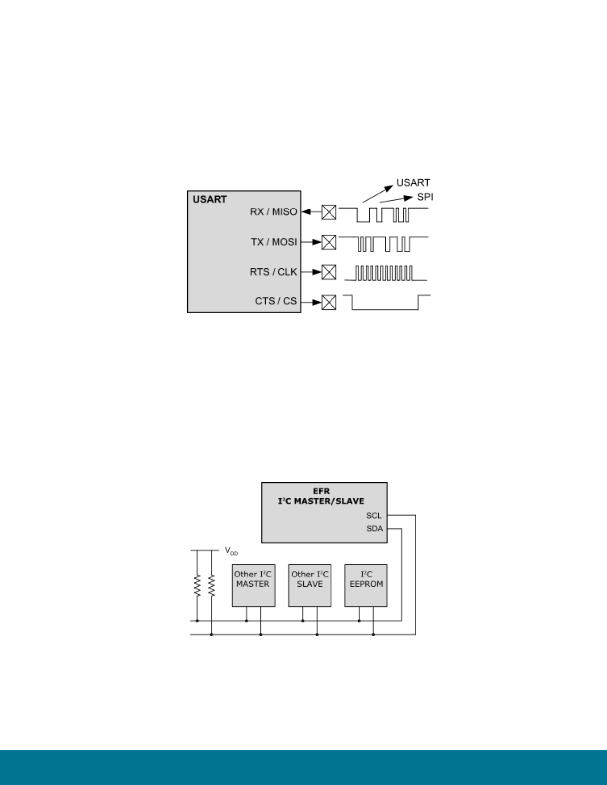
3.1 USART
The Universal Synchronous/Asynchronous Receiver/Transmitter is a flexible serial I/O module. It supports full duplex asynchronous
UART communication with hardware flow control as well as SPI.
If UART is used as BGAPI serial protocol host interface it is strongly recommended to use RTS and CTS signals for reliable data transmission.
Figure 3.1. USART
3.2 Low Energy Universal Asynchronous Receiver/Transmitter (LEUART)
The unique LEUART™ provides two-way UART communication on a strict power budget. Only a 32.768 kHz clock is needed to allow
UART communication up to 9600 baud. The LEUART includes all necessary hardware to make asynchronous serial communication
possible with a minimum of software intervention and energy consumption.
3.3 I2C
The I2C module provides an interface between the MCU and a serial I2C bus. It is capable of acting as both a master and a slave.
Standard-mode, fast-mode and fast-mode plus speeds are supported, allowing transmission rates from 10 kbit/s up to 1 Mbit/s.
Figure 3.2. I2C
3.4 Timer/Counter (TIMER)
TIMER peripherals count events, generate PWM outputs. The core of each TIMER is a 16-bit counter.
silabs.com | Smart. Connected. Energy-friendly. Rev. 0.96 | 3

®
Blue Gecko BGM111 Bluetooth
Smart Module Data Sheet
Interfaces
3.5 Real Time Counter
The Real Time Counter is a 32-bit counter providing timekeeping in all energy modes and it is capable of providing system wake-up at
user defined instances. The RTCC includes 128 bytes of general purpose data retention, allowing easy and convenient data storage in
all energy modes.
3.6 Low Energy Timer (LETIMER)
The unique LETIMER™ is a 16-bit timer that is available in energy mode EM2 DeepSleep in addition to EM1 Sleep and EM0 Active.
This allows it to be used for timing and output generation when most of the device is powered down, allowing simple tasks to be performed while the power consumption of the system is kept at an absolute minimum. The LETIMER can be used to output a variety of
waveforms with minimal software intervention.
3.7 Ultra Low Power Wake-Up Timer (CRYOTIMER)
The CRYOTIMER is a 32-bit counter that is capable of running in all energy modes. It can be clocked by either the 32.768 kHz crystal
oscillator (LFXO), the 32.768 kHz RC oscillator (LFRCO) or the 1 kHz RC oscillator (ULFRCO). It can provide periodic Wakeup events
and PRS signals which can be used to wake up peripherals from any energy mode. The CRYOTIMER provides a wide range of interrupt periods, facilitating flexible ultra-low energy operation.
3.8 Pulse Counter (PCNT)
The Pulse Counter (PCNT) peripheral can be used for counting pulses on a single input or to decode quadrature encoded inputs.
3.9 General Purpose Input/Output (GPIO)
BGM111 has 25 General Purpose Input/Output pins. Each GPIO pin can be individually configured as either an output or input. More
advanced configurations including open-drain, open-source, and glitch-filtering can be configured for each individual GPIO pin. The
GPIO pins can be overridden by peripheral connections, like SPI communication. Each peripheral connection can be routed to several
GPIO pins on the device. The GPIO subsystem supports asynchronous external pin interrupts.
When configured as GPIO output drive strength can be applied to pins on port by port basis and it can be either 1 mA or 10 mA.
3.10 Analog Comparator (ACMP)
The Analog Comparator is used to compare the voltage of two analog inputs, with a digital output indicating which input voltage is higher. Inputs are selected from among internal references and external pins. The tradeoff between response time and current consumption
is configurable by software. The ACMP can also be used to monitor the supply voltage from software. An interrupt can be generated
when the supply falls below or rises above a programmable threshold.
3.11 Analog to Digital Converter (ADC)
The ADC is a Successive Approximation Register (SAR) architecture, with a resolution of up to 12 bits up to 1 Msamples/sec. The output sample resolution is configurable and additional resolution is possible using integrated hardware for averaging over multiple samples. The ADC includes integrated voltage references and an integrated temperature sensor. Inputs are selectable from a wide range of
source, including pins configurable as either single-ended or differential.
3.12 Digital to Analog Current Converter (IDAC)
The Digital to Analog Current Converter can source or sink a configurable constant current. This current can be driven on an output pin
or routed to the selected ADC input pin for capacitive sensing. The current is programmable between 0.05 μA and 64 μA with several
ranges with various step sizes.
3.13 Integrated DC-DC Converter (DC-DC)
The DC-DC buck converter covers a wide range of load currents and provides high efficiency in energy modes EM0, EM1, EM2 and
EM3. The converter operates in active and bypass operating modes. Bypass mode may be entered when the input voltage is too low
for efficient operation of the DC-DC converter. In Bypass mode, the DC-DC input supply is internally connected directly to its output
through a low resistance switch. Bypass mode also supports in-rush current limiting to avoid dipping the input supply due to excessive
current transients.
Note:
• When DC/DC is enabled, supply voltage range is 2.4V to 3.8V.
• When DC/DC is disabled, supply voltage range is 1.8V to 3.8V.
silabs.com | Smart. Connected. Energy-friendly. Rev. 0.96 | 4
Blue Gecko BGM111 Bluetooth® Smart Module Data Sheet
4. Antenna
This section contain design guidelines and recommendations for the BGM111 antenna.
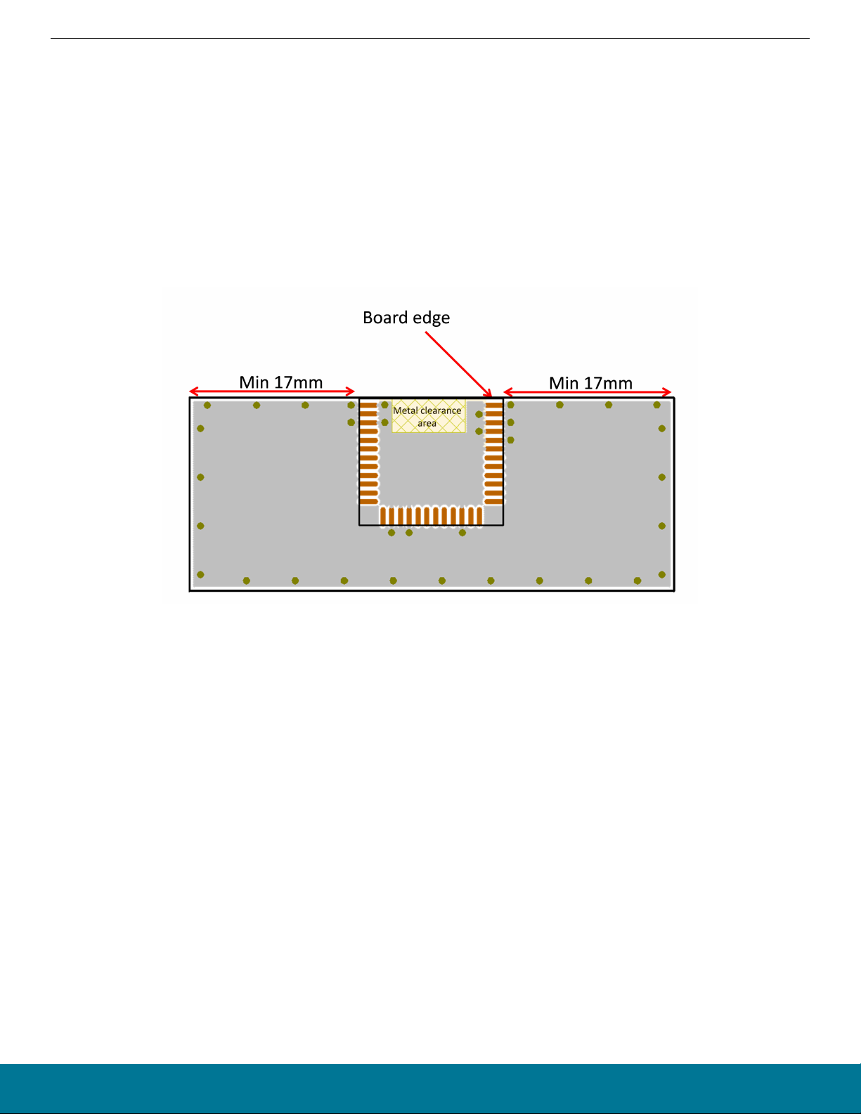
4.1 PCB Design Guidelines
For optimal performance of the BGM111, please follow the following guidelines:
• Place the module at the edge of the PCB as shown in the the figure below.
• Do not place any metal (traces, components, battery etc.) within the clearance area of the antenna.
• Connect all the GND pins directly to a solid GND plane.
• Place the GND vias as close to the GND pins as possible.
• Do not place plastic or any other dielectric material in touch with the antenna.
Antenna
Figure 4.1. Recommended Layout for BGM111
silabs.com | Smart. Connected. Energy-friendly. Rev. 0.96 | 5
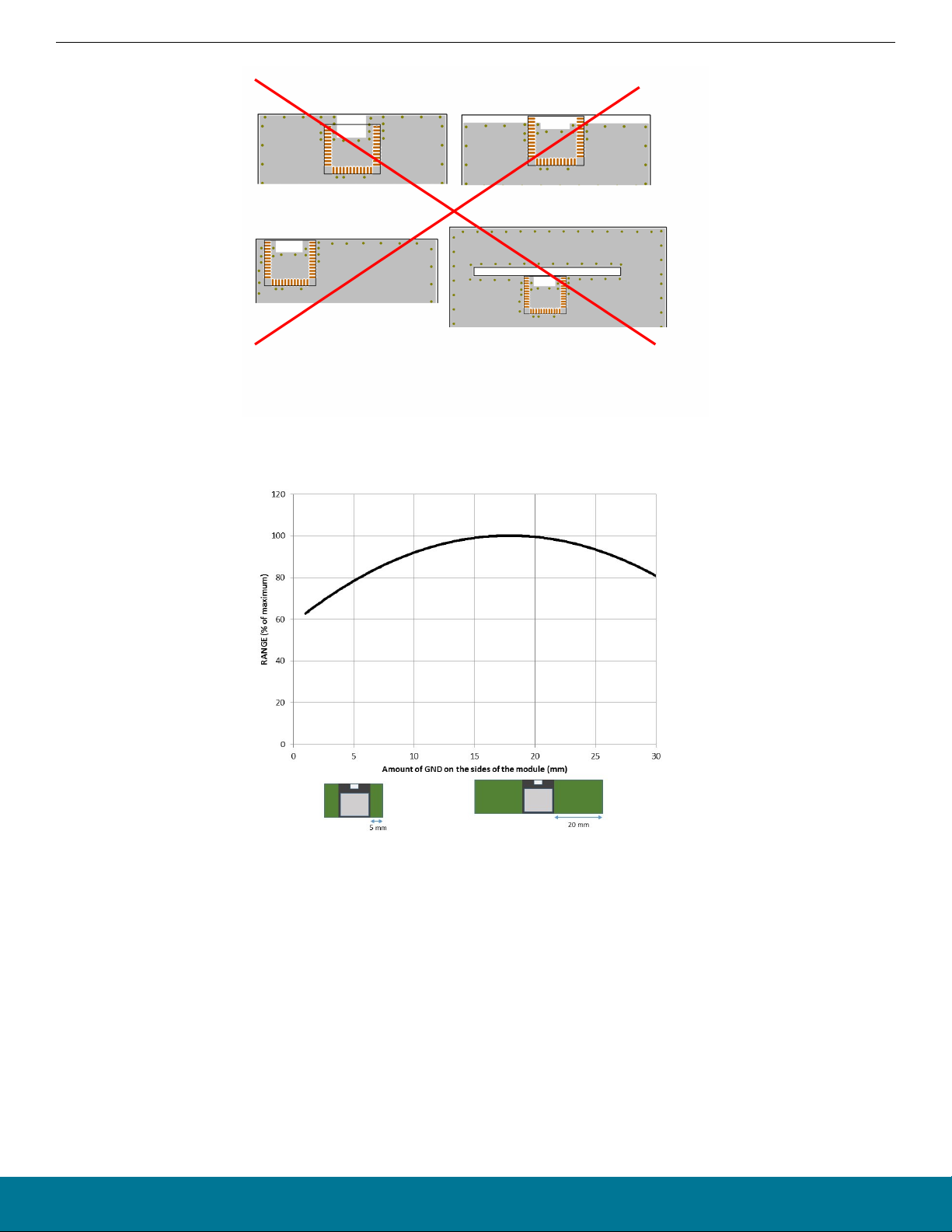
Blue Gecko BGM111 Bluetooth
Figure 4.2. Poor Layouts for BGM111
®
Smart Module Data Sheet
Antenna
Figure 4.3. Impact of the Size of GND Plane to the BGM111 Range
4.2 Effect of Plastic and Metal Materials
Do not place plastic or any other dielectric material in touch with the antenna.
Any metallic objects in close proximity to the antenna will prevent the antenna from radiating freely. The minimum recommended distance of metallic and/or conductive objects is 10 mm in any direction from the antenna except in the directions of the application PCB
ground planes.
4.3 Locating the Module Close to Human Body
Note: Placing the module in touch or very close to the human body will have a negative impact on the efficiency of the antenna thus
reducing range.
silabs.com | Smart. Connected. Energy-friendly. Rev. 0.96 | 6

Blue Gecko BGM111 Bluetooth
®
Smart Module Data Sheet
Hardware Design Guidelines
5. Hardware Design Guidelines
The BMG111 is an easy-to-use module with regard to hardware application design but certain design guidelines must be followed to
guarantee optimal performance. These guidelines are listed in the next sub-sections.
5.1 Power Supply Requirements
Coin cell batteries cannot withstand high peak currents (e.g. higher than 15 mA). If the peak current exceeds 15 mA it’s recommended
to place 47 - 100 µF capacitor in parallel with the coin cell battery to improve the battery life time. Notice that the total current consumption of your application is a combination of the radio, peripherals and MCU current consumption so you must take all of these into account. BGM111 should be powered by a unipolar supply voltage with nominal value of 3.3 V. Operating voltage range of the module is
2.4 - 3.8 V when using the built-in DC/DC converter.
External high frequency bypass capacitors are not needed because the module contains the required supply filter capacitors. However,
care should be taken to prevent strong switching noise from being superimposed on the supply line. Such noise can be generated e.g.
by on-board charge pump converters used in RS232 level shifters. If this type of switching noise is present, a power filter circuit on the
VDD input is recommended. Note that there is a total of about 4.8 µF of low ESR ceramic capacitors on the VDD line inside the module.
When using low-dropout linear regulators to generate a regulated supply for the VDD line, the stability of the regulator with the low ESR
provided by these capacitors should be checked. Many linear regulators and also some switched mode regulators are not stable when
using ceramic output capacitors. The datasheet of the regulator typically lists recommendations concerning suitable capacitors including data on ESR range and/or stability curves. A regulator which is stated “stable with ceramic capacitors” is recommended.
5.2 Power Saving Functions
EM power saving modes are automatically controlled by the firmware and it always enters the lowest possible power save mode possible depending on the radio, peripheral and software activity.
5.3 Reset Functions
The BGM111 can be reset by three different methods: by pulling the RESET line low, by the internal watchdog timer or software command. The reset state in BGM111 does not provide any power saving functionality and thus is not recommended as a means to conserve power. BGM111 has an internal system power-up reset function. The RESET pin includes an on-chip pull-up resistor and can
therefore be left unconnected if no external reset switch or source is needed.
5.4 Debug and Firmware Updates
This section contains information on debug and firmware update methods.
5.4.1 JTAG
It is recommended to expose the JTAG debug pins in your own hardware design for firmware update and debug purposes. The following table lists the required pins for JTAG connection.
The debug pins have pull-down and pull-up enabled by default, so leaving them enabled may increase current consumption if left connected to supply or ground. If enabling the JTAG pins the module must be power cycled to enable a SWD debug session.
Table 5.1. JTAG Pads
PAD NAME PAD NUMBER JTAG SIGNAL NAME COMMENTS
PF3 24 TDI This pin is disabled after reset. Once enabled the pin has a built-in pull-up.
PF2 23 TDO This pin is disabled after reset
PF1 22 TMS Pin is enabled after reset and has a built-in pull-up
PF0 21 TCK Pin is enabled after reset and has a built-in pull-down
5.4.2 DFU
It is also possible to update the firmware over UART using DFU protocol. However the bootloader cannot be updated using DFU but
requires that the firmware is updated using JTAG.
silabs.com | Smart. Connected. Energy-friendly. Rev. 0.96 | 7
Blue Gecko BGM111 Bluetooth® Smart Module Data Sheet
Bluetooth Stack Software
6. Bluetooth Stack Software
Silicon Labs’ Bluetooth Smart Software is a complete Bluetooth Smart software stack for the BGM111 Bluetooth Smart module. The
software implements a full Bluetooth LE compatible stack and L2CAP, RFCOMM, SMP and ATT protocols along with any GATT based
Bluetooth Smart profiles.
The Bluetooth Smart Ready Software also is supported by a complete SDK for developing Bluetooth Smart applications using either an
external host with the BGAPI™ serial protocol over UART or fully standalone applications based on a simple scripting language called
BGScript™.
Several profiles and software project examples are offered as part of the Bluetooth Smart SDK to help expedite the development of
Bluetooth Smart compatible end-user products.
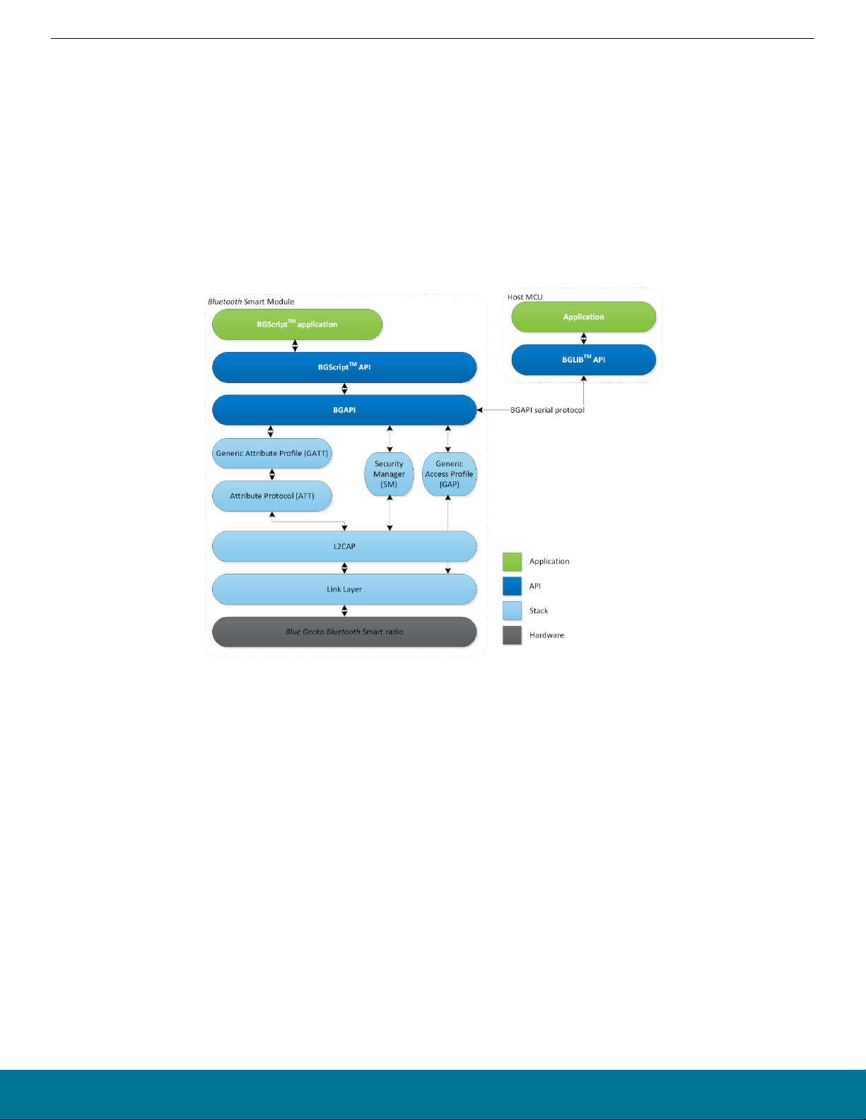
The main parts of the Bluetooth Smart software stack are shown below.
Figure 6.1. Bluetooth Smart Ready Software Stack
Note: To learn more about the Bluetooth Smart software stack, the SDK, and the APIs please read QSG108: Blue Gecko Bluetooth
Smart Software Quick-Start Guide.
silabs.com | Smart. Connected. Energy-friendly. Rev. 0.96 | 8
Blue Gecko BGM111 Bluetooth® Smart Module Data Sheet
Host Interface
7. Host Interface
This section contains information about the host interface available on the BGM111 module.
7.1 UART
The BGM111 can be controlled over the UART interface as a peripheral to an external processor. In order for the communication to be
reliable, hardware flow control signals (RTS and CTS) must be present between the host and the module. For baud rates exceeding
115200 kbps the controlling processor should have a clock frequency accurate to within 1% in order for the UART signaling to work
reliably.
When UART is used as a host interface (network co-processor mode) two optional I/O pins can be used either to wake-up the BGM111
from EM2 sleep mode when the host has commands or data to send or alternatively to wake-up the host when the BGM111 has events
or data to the host.
Default UART settings are listed below:
Table 7.1. BGM111 UART Interface Default Settings
Parameter Default setting
UART baud rate 115200 kbs
RTS/CTS flow control Enabled
Data bits 8
Parity None
Stop bits 1
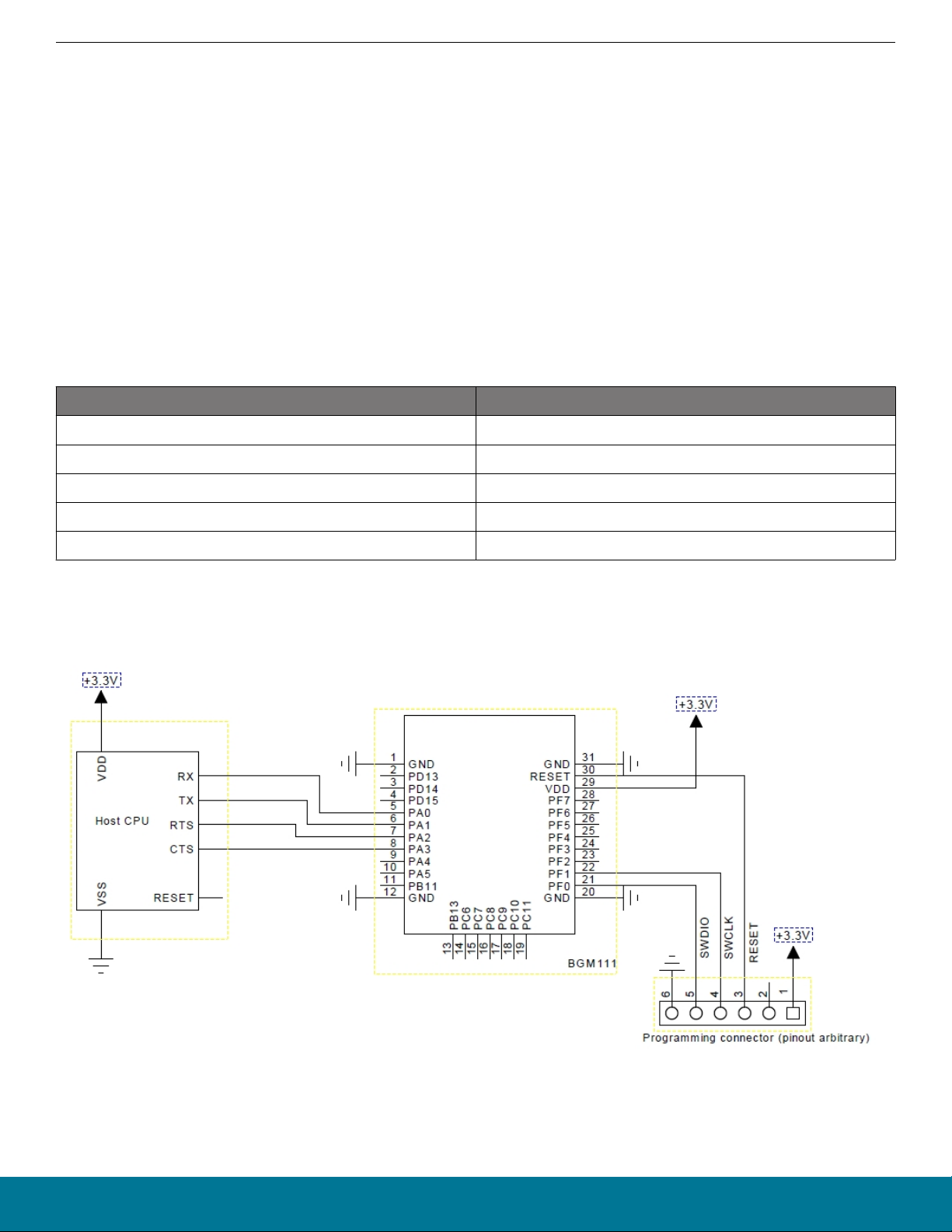
The figure below shows the recommended layout for connecting BGM111 with an external host.
Note: A programming connector as shown in the figure below must be available in the design for BGM111 firmware update.
Figure 7.1. Connecting BGM111 with an external host
silabs.com | Smart. Connected. Energy-friendly. Rev. 0.96 | 9
 Loading...