

Silicon Laboratories Finland BGM111 Installation guide
INSTALLATION GUIDE
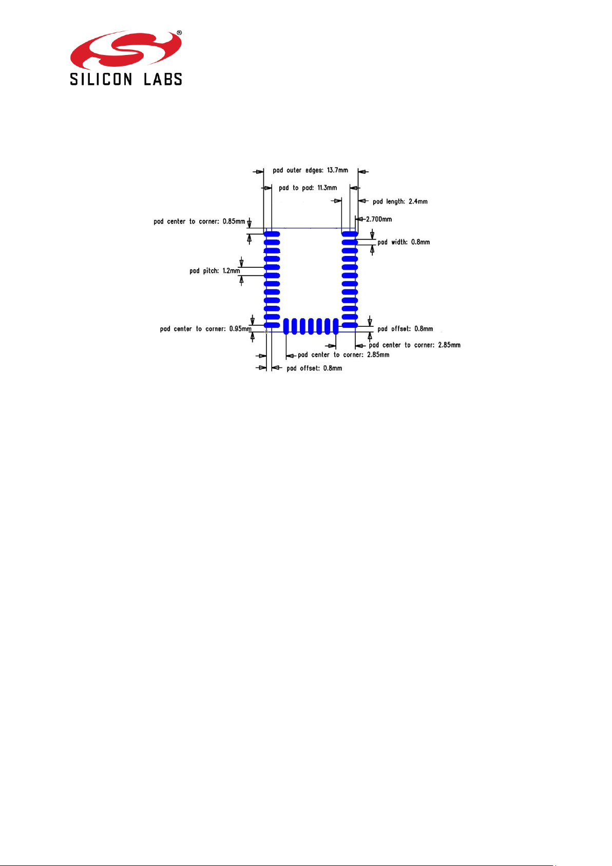
Figure 1: Recommended PCB land pattern of BGM111E
Because BGM111E is using an external antenna through the embedded u.fl connector, the
radiated performance does not depend on the PCB layout. The module can be placed freely
in the application board. It is recommended to use good engineering practices in the layout
to avoid RF noise coupling and EMI issues.
Alberga Business Park, Bertel Jungin aukio 3
FI-02600 Espoo, Finland
Phone: +358 9 435 5060
www.silabs.com

QUALIFIED ANTENNA TYPES FOR
BGM111E
BGM111E module is approved with a standard 2.14 dBi dipole antenna. Any antenna of the
same type, similar in-band out of band characteristics and with the same or less gain can be
used without reassessment. In case using antenna of a different type and/or higher gain
reassessments and notification to the particular certification authority is required.
Page 2 of 7
Japan
R 209-J00240
BGM111E is certified in Japan with certification number 209-J00240.
It is recommended that a manufacturer who integrates a radio module in their host
equipment will place the certification mark and certification number (the same
marking/number as depicted on the label of the radio module) on the outside of the host
equipment. The certification mark and certification number must be placed close to the text
in the Japanese language which is provided below. This change in the Radio Law has been
made in order to enable users of the combination of host and radio module to verify if they
are actually using a radio device which is approved for use in Japan.
当該機器には電波法に基づく、技術基準適合証明等を受けた特定無線設備を装着している。
Translation:
“This equipment contains specified radio equipment that has been certified to the Technical
Regulation Conformity Certification under the Radio Law.”
Figure 2: GITEKI mark and ID
Page 3 of 7
 Loading...