

Page 1
UG171: ZigBee® Smart Outlet Reference
Design (RD-0051-0201) Kit User's Guide
Silicon Labs' compact and cost-effective smart outlet reference design is based on ZigBee HA (Home Automation) 1.2 standard and can be used in conjunction with a ZigBee
HA 1.2 home automation system. This reference design kit features Silicon Labs’
EFR32MG1P232F256GM48 ZigBee Pro Wireless Microcontroller (MCU), the Si7021
temperature and relative humidity sensor, and the Si1141 ambient light sensor. This
document contains instructions and guidelines for the following: a quick-start demonstration and next steps, system overview and operations, hardware and firmware considerations, and engineering and manufacturing testing.
This guide applies to EmberZNet PRO 5.8 and later.
KEY POINTS
• Quick start demonstration
• Recommended next steps
• Kit overview
• Device operation
• HA 1.2 and FCC certifiable
• Hardware and Firmware Considerations
• Ecosystem considerations
• Engineering and Manufacturing Testing
silabs.com | Smart. Connected. Energy-friendly. Rev. 0.1
Page 2

®
UG171: ZigBee
Smart Outlet Reference Design (RD-0051-0201) Kit User's Guide
Introduction
1. Introduction
There is an increasing desire in the market for a standards-driven, low-cost, and low-power wireless home automation system. For
many entrant systems a smart outlet is usually employed to remotely activate and deactivate the source power feeding into room
lamps, personal fans, and consumer electronics. In addition to home automation, consumers are employing an array of low-cost sensors to further enhance their home automation’s autonomous behavior. Silicon Labs has developed a compact and cost-effective smart
outlet reference design targeted at these applications. This reference design (see the following figure) features Silicon Labs’
EFR32MG1P232F256GM48 ZigBee Pro Wireless Microcontroller (MCU), the Si7021 temperature and relative humidity sensor. and the
Si1141 ambient light sensor. The outlet also features voltage, current, and power measurement capability, as well as current and thermal overload shutdown features. The reference design can be directly integrated into a connected ZigBee home automation application, as shown in Figure 1.2 ZigBee Home Automation with Smart Outlets on page 1. The reference design comes preprogrammed
and fully functional out of the box. All hardware design files and firmware application source code are available.
ZigBee HA 1.2
Gateway
Figure 1.1. ZigBee Smart Outlet Reference Design
ZigBee
Smart
Outlet
ZigBee
Smart
Outlet
ZigBee
Smart
Outlet
Figure 1.2. ZigBee Home Automation with Smart Outlets
silabs.com | Smart. Connected. Energy-friendly. Rev. 0.1 | 1
Page 3

UG171: ZigBee® Smart Outlet Reference Design (RD-0051-0201) Kit User's Guide
Quick Start Demonstration
2. Quick Start Demonstration
A video showing the quick-start demonstration is available at http://www.silabs.com/zigbeesmartoutlet.
1. Set up an HA 1.2 ZigBee gateway.
2. Supply power to the ZigBee Smart Outlet.
a. Ensure the reference design is connected to a main power source. Note that the outlet power supply is rated to 240 VAC,
however, the the North American plug is rated to 120 VAC.
b. The reference design is powered when the green LED momentarily flashes at least once.
3. Connect the ZigBee Smart Outlet to the ZigBee network.
a. Follow the directions provided with the ZigBee gateway to enable the smart outlet reference design to join its ZigBee network.
b. Depress and hold external front button for more than three seconds, then release to begin the network join procedure.
c. The outlet has joined the ZigBee network when the green LED blinks six times.
4. Demonstrate ZigBee Smart Outlet functionality.
a. Send an “on” command from the gateway to the smart outlet. This should cause an audible click to occur (from the internal
relay), the red LED will blink once and power will be applied to the front female plug outlet.
b. Send an “off” command from the gateway to the smart outlet. This should cause an audible click to occur (from the internal
relay), the red LED will blink once and power will be removed to the front female plug outlet.
c. To manually provide or remove power from the female front outlet, hold the front button for more than half a second, but less
than two seconds to toggle between states.
d. If supported by the gateway, the on-board sensors on the reference design can be viewed by the user interface of the gate-
way.
silabs.com | Smart. Connected. Energy-friendly. Rev. 0.1 | 2
Page 4

UG171: ZigBee® Smart Outlet Reference Design (RD-0051-0201) Kit User's Guide
Recommended Next Steps
3. Recommended Next Steps
A video showing the recommended next steps is available at http://www.silabs.com/zigbeesmartoutlet.
3.1 Evaluate the Smart Outlet
The ZigBee smart outlet reference design can support most smart power outlet application requirements. Typical areas of evaluation
include:
1. ZigBee network behavior, such as network join and leave.
2. Deploying on-off commands remotely.
3. Measuring energy consumption of the controlled load.
4. Monitoring ambient temperature, humidity, and ambient light.
5. RF performance, such as range.
3.2 Evaluate the Firmware
If firmware modification is needed to support your application:
1. Visit the ZigBee Getting Started page and order a development kit.
2. Refer to Section 7. Firmware of this document.
3.3 Build Proof of Concept
Out of the box, the smart outlet reference design can be used for a rapid proof of concept. One can demonstrate the look, feel, and
function of a final product. Refer to Section 7. Firmware to change functional behavior, such as LED blinking or button functionality.
3.4 System Integration
Section 6. Hardware of this document describes the considerations for integrating the reference design into a typical application. Often
the reference design can be designed into a system without modification. In cases where a change is required, the hardware section of
this document also offers modification guidelines.
3.5 Engineering and Manufacturing Tests
Section 9. Engineering Tests of this document provides engineering test information for UL, such as FCC and HA 1.2.
Section 10. Manufacturing Tests of this document offers considerations for simplified manufacturing tests.
3.6 Manufacturing
Please contact Silicon Labs to access our manufacturing partner network for the reference design, or a modified version of the design.
silabs.com | Smart. Connected. Energy-friendly. Rev. 0.1 | 3
Page 5
UG171: ZigBee® Smart Outlet Reference Design (RD-0051-0201) Kit User's Guide
Overview
4. Overview
4.1 Part Numbers
The part number convention is RD-XXXX-YYYY, where:
RD Reference Design
XXXX Reference Design Number
YYYY Reference Design Component
This document will use the reference design number (RD-XXXX) when describing the complete design, and the reference design component (RD-XXXX-YYYY) when describing a specific component.
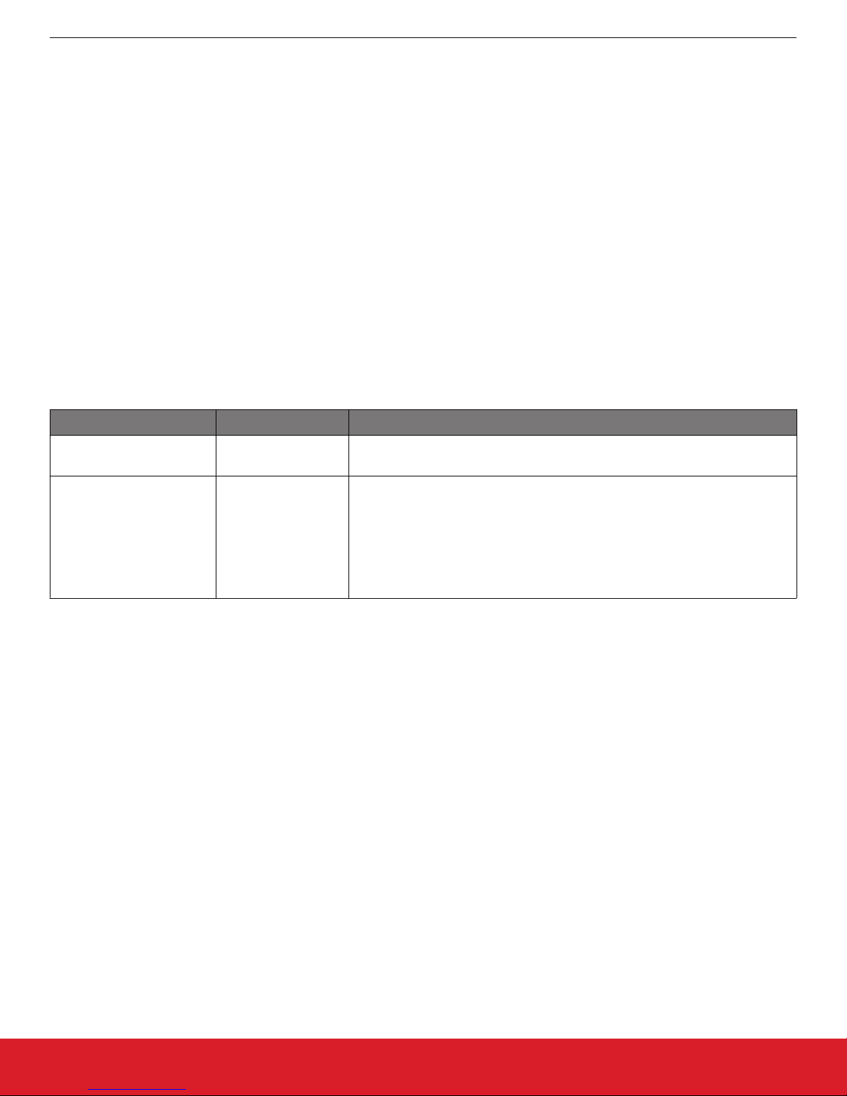
The following table provides a description and PCB marking for each part number.
Note: Some cases lack sufficient space on the PCB, and an internal “IST” marking appears on the PCB instead of the “RD” part number.
Table 4.1. Part Numbers and Description
Part Number PCB Marking Description
RD-0051-0201 NA ZigBee Smart Outlet Reference Design Kit with North America plug using
EFR32MG1P232F256GM48, Si7021, Si1141 and PCB Antenna.
RD-0051-0101 IST-A0081 rev 2.0
(Power Board)
IST-A0074 rev 4.0
(Radio Board)
IST-A0075 rev 2.0
(Sensor Board)
4.2 ZigBee Smart Outlet Reference Design Kit
Kit Contents:
• ZigBee smart outlet reference design.
• Quick start card to obtain the latest reference design collateral.
ZigBee Smart Outlet Reference Design Evaluation Board with North America
plug using EFR32MG1P232F256GM48, Si7021, Si1141 and PCB Antenna.
silabs.com | Smart. Connected. Energy-friendly. Rev. 0.1 | 4
Page 6
®
UG171: ZigBee
Smart Outlet Reference Design (RD-0051-0201) Kit User's Guide
4.3 ZigBee Smart Outlet Reference Design
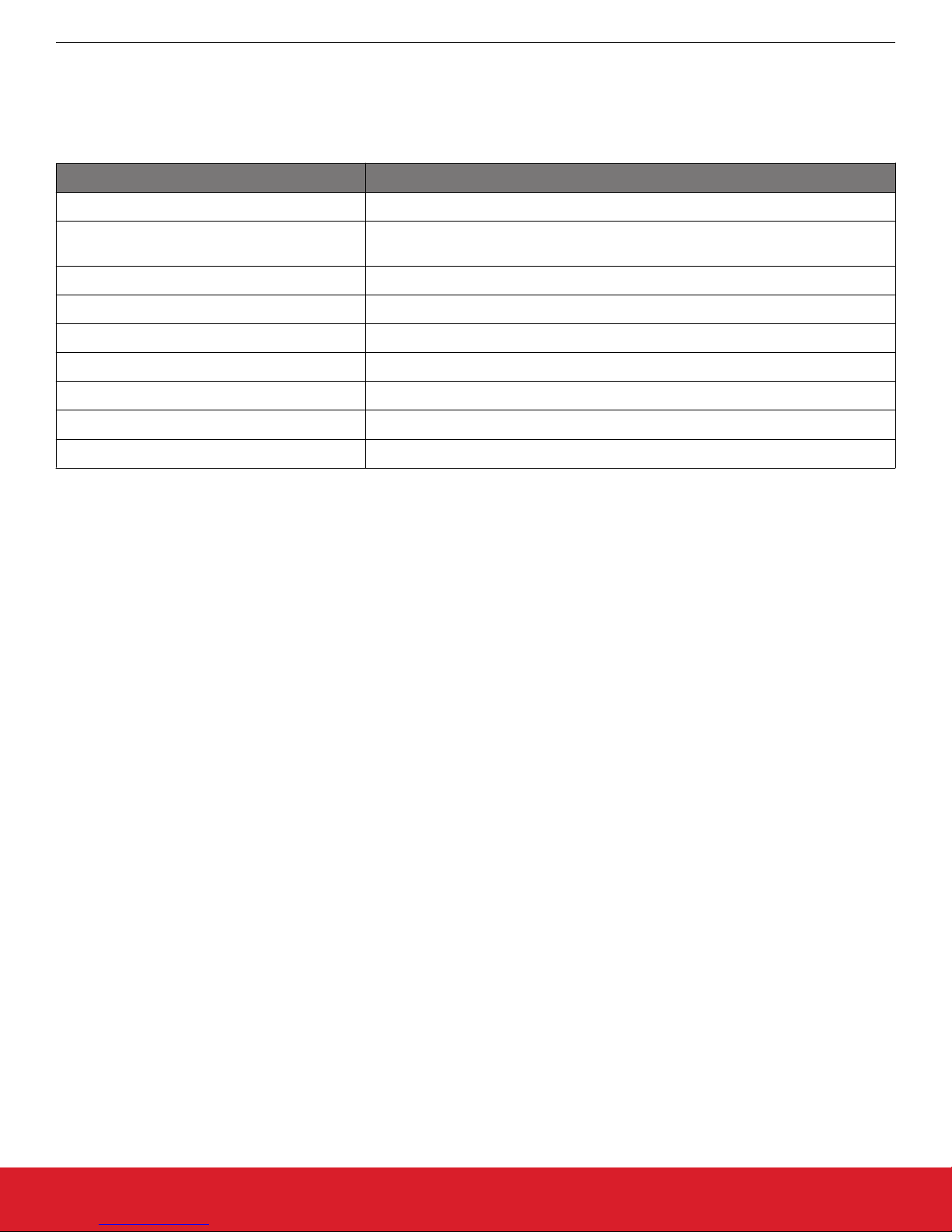
This reference design contains many features for the evaluation of a smart outlet, including:
Table 4.2. ZigBee Smart Outlet Reference Design Features
Reference Design Features Benefit
15 A power relay Allows for power control of most household electronic products.
Energy monitoring circuit Provides power, voltage and current status of a device being powered by the refer-
ence design.
Temperature and relative humidity sensor Provides room environmental sensing capability.
Ambient light sensor Provides room lighting status information in proximity to the reference design.
Network status LED Provides feedback on the RF network status.
Power status LED Provides feedback on the power circuitry.
10-pin Mini Simplicity Connector Facilitates ZigBee packet trace and debugging.
User button Eases network commissioning (join/leave) and manual power override.
Test points Simplifies hardware-level debugging.
Overview
4.4 Hardware Features
The smart outlet hardware reference design contains the following features:
• Silicon Labs EFR32MG1P232F256GM48 ZigBee Pro Radio:
• 32-bit ARM® Cortex -M4 with DSP and FPU
• 2.4-GHz IEEE 802.15.4-2003 transceiver & lower MAC.
• Hardware Cryptographic Acceleration for AES 128/256, SHA-1, SHA-2 (SHA-224 and SHA-256) and ECC.
• 256 kB user programmable flash with 64 kB RAM.
• Flexible ADC, UART/SPI/I2C serial communications, and general purpose timers.
• Highly efficient Thumb-2 instruction set.
• Silicon Labs Si7021 relative humidity and temperature sensor:
• Temperature sensor accuracy: ±0.4 °C
• Humidity sensor accuracy: ±3% RH
• I2C interface
• Silicon Labs Si1141 ambient light sensor:
• Ambient light sensor range: 1 to 128 kilo lux
• I2C interface
• Additional hardware features:
• Integrated PCB antenna.
• Energy monitoring device
• Full packet trace port for RF communications debugging.
• Pushbutton for manual on-off power and network join.
• Green Network/status LED.
• Red power status LED.
• Fully qualified BOM for 0 to 55 ºC operation.
• Pre-certified FCC Part 15.
• Pre-certified UL.
silabs.com | Smart. Connected. Energy-friendly. Rev. 0.1 | 5
Page 7

UG171: ZigBee® Smart Outlet Reference Design (RD-0051-0201) Kit User's Guide
Overview
4.5 Firmware Features
The reference design firmware application contains the following features:
• Pre-compiled and source application firmware.
• Over-the-Air (OTA) upgradable.
• ZigBee HA 1.2 pre-certifiable clusters: Basic, Identify, On/Off, Metering, Temperature Measurement, Electrical Measurement, Diagnostics, and OTA Cluster.
•
Application firmware (source code) available in the EmberZNet™ PRO stack library 5.8.0 and later.
silabs.com | Smart. Connected. Energy-friendly. Rev. 0.1 | 6
Page 8

UG171: ZigBee® Smart Outlet Reference Design (RD-0051-0201) Kit User's Guide
Operation
5. Operation
Three types of button presses are defined. A short button press is less than 500ms, a medium button press is 500ms to 2 seconds, and
a long press is greater than 3 seconds. In cases where more than one short button press is required, there may be no more than two
seconds between each press.
5.1 Outlet Behavior
5.1.1 Remote Control
The ZigBee smart outlet reference design utilizes a 15A controllable relay to manually or remotely toggle power to a device connected
to the front female outlet of the device. If it receives an “on” command from the gateway it will close the relay contact to supply power to
the load. If it receives an “off” command from the gateway it will open the relay contact to prevent power to the load. When the outlet
changes state from off to on the red LED will turn on for one second. When the outlet changes state from on to off the red LED will turn
on for 250 ms.
5.1.2 Manual Control
The state of the outlet may be toggled with medium press of the button. When the outlet changes state from off to on the red LED will
turn on for one second. When the outlet changes state from on to off the red LED will turn on for 250 ms.
5.1.3 Overload Protection and Indication
The switch features current and thermal overload protection and indication. If current or thermal overload is detected the outlet will disable power. For current overload indication the red LED will blink 250 ms on and 750 ms off, for two minutes. For thermal overload indication the red LED will blink 250 ms on and 250 ms off, for two minutes. If the overload condition is still present after the two minute
indication, the cycle will repeat.
5.1.4 AC Power Sensing and Energy Measurements
The reference design uses a Cirrus Logic CS5463 power/energy IC is used to measure various attributes of the mains power input.
While the device provides an array of attributes, the following data is collected by this reference design as they are relevant for a lowcost, smart outlet:
• RMS Voltage
• RMS Current
• Active Power
• AC Alarms Mask
• AC Voltage Overload
• AC Current Overload
• AC Active Power Overload
silabs.com | Smart. Connected. Energy-friendly. Rev. 0.1 | 7
Page 9

UG171: ZigBee
®
Smart Outlet Reference Design (RD-0051-0201) Kit User's Guide
Operation
5.2 ZigBee Network Behavior
This section describes the various operational states that the smart outlet reference design is able to occupy as it joins and leaves a
ZigBee network. The input mechanism for operation utilizes the external push button. The green LED and red LED operates as output
signaling information as the reference design traverses or occupies a functional state.
Figure 5.1. Device Operation State Diagram
5.2.1 Power-up
After the hardware has been powered for the first time, the device will be in a factory default mode and will be placed in the ACTIVE
NTWK SEARCH state. If the reference design successfully joins a network and is powered off at a later time, upon re-powering, it will
return to the ON NETWORK state.
5.2.2 OFF NETWORK State
This state is a condition where the design is not connected to a network and is not searching for a network. To leave this state and
enter the ACTIVE NTWK SEARCH state, press the button one time.
5.2.3 ACTIVE NTWK SEARCH State
This state is a condition where the reference design is actively searching for a network but has not yet joined a network. While in this
mode, the green LED will flash once every two seconds. This operation of actively searching for a network will remain for up to 20
scans of the band, or approximately 160 seconds. If no network is found, the reference design will enter into the OFF NETWORK state.
Power-cycling or a button press while in this state will reset the timer, while keeping the reference design in this state. If a joinable
network is found it will leave this state and enter the NETWORK JOIN state.
5.2.4 NETWORK JOIN State
After leaving the ACTIVE NTWK SEARCH state and entering this state, the green LED will flash six times in three seconds to indicate
successfully finding and joining a network. This state is temporary and will place the reference design into the ON NETWORK state
once the green LED completes its flash sequence.
silabs.com | Smart. Connected. Energy-friendly. Rev. 0.1 | 8
Page 10

UG171: ZigBee® Smart Outlet Reference Design (RD-0051-0201) Kit User's Guide
Operation
5.2.5 ON-NETWORK State
The ON-NETWORK state is a condition where the smart outlet reference design is connected to a ZigBee network and is not searching
for another network. This state contains multiple entry and exit paths depending on various factors.
If power to the reference design is removed and later restored, the reference design will not seek other networks unless the user forces
it to leave its joined network (as will be described within this section).
If the button is short-pressed once for more than three seconds, the reference design will enter the LEAVE NETWORK state.
If the button is short-pressed two times, the reference design will temporarily enter the IDENTIFY state while remaining on its joined
network.
If the button is short-pressed three times, the reference design will temporarily enter the NETWORK STATUS state while remaining on
its joined network.
If the button is short-pressed five times, the reference design will enter the NETWORK IDENTIFY state.
5.2.6 IDENTIFY State
The purpose of this state is to help an installer (or user) identify which device is communicated to by visually flashing the green LED in
a specified pattern to locate the targeted device. After the reference design leaves the ON-NETWORK state and enters this state, the
green LED will flash twice every two seconds for two minutes. This state is temporary, and the reference design will return to the ONNETWORK state once the state’s timer reaches its time limit.
5.2.7 NETWORK STATUS State
The purpose of this state is to help an installer (or user) to identify if a device is successfully connected to a network. After the reference
design leaves the ON-NETWORK state and enters this state, the green LED will flash six times in three seconds if on a network. This
state is temporary, and the reference design will return to the ON-NETWORK state.
5.2.8 SEND IDENTIFY State
The purpose of the SEND IDENTIFY state is to send an identify request to a gateway. It is then up to the gateway to react as desired to
the request.
5.2.9 LEAVE NETWORK State
Upon entering this state, the smart outlet reference design will leave the joined network and will indicate this process is in action by
flashing the green LED three times in three seconds. This state is temporary and will place the reference design into the ACTIVE
NTWK SEARCH state once the LED completes its flash sequence.
silabs.com | Smart. Connected. Energy-friendly. Rev. 0.1 | 9
Page 11

®
UG171: ZigBee
Smart Outlet Reference Design (RD-0051-0201) Kit User's Guide
Hardware
6. Hardware
This section describes the key aspects of the reference design.
6.1 ZigBee Smart Outlet Reference Design
The reference design is composed of three printed circuit boards:
• RF board
• Sensor board
• Power board
The RF board mounts on the power board via connectors. The sensor board mounts to the power board with a ribbon cable connector.
6.1.1 RF Board Highlights
• ERF32MG ZigBee Pro radio with an embedded flash
• Cirrus Logic CS5463 energy monitoring IC
• Printed circuit board antenna
• Mini-simplicity header debug connector
6.1.2 Sensor Board Highlights
• Si7021 temperature and humidity sensor
• Si1141 ambient light sensor
• Momentary push button
6.1.3 Power Board Highlights
• TI UCC28700DBV constant voltage, constant current, fly-back controller
• TI LM3671MF switching regulator 3.3 V, 600 mA
• TE Connectivity 8-1393239-5 SPDT relay 250 VAC, 16 A
• Diodes Incorporated RH06-T bridge rectifier 600 V, 0.5 A
• Renco RLTI-1072 transformer 40:3, 2A
• Bel Fuse slow blow fuse 250 V, 0.5A
• Green and red LEDs
6.2 Hardware Modification Guidelines
For users who wish to modify the reference design, we offer guidelines below for what to expect in the modification process.
6.2.1 Avoid Modification
All changes listed here may have serious impacts on performance or certification passage such as FCC or UL:
• Modifying the spacing between the EM3587, FEM and the PCB antenna.
• Modifying the high voltage sections of the power board.
• Changing the PCB antenna length/shape.
• Changing any part of the ground pour area.
6.2.2 Bill of Material Cost-saving Options
To further reduce overall bill-of-material (BOM) cost of this reference design, the following items and their supporting circuitry can be
considered for removal:
• Mini-simplicity programming header.
• CS5463 and its supporting energy monitoring circuitry.
• Si1141 ambient light sensor.
• Si7021 temperature and humidity sensor.
silabs.com | Smart. Connected. Energy-friendly. Rev. 0.1 | 10
Page 12

®
UG171: ZigBee
Smart Outlet Reference Design (RD-0051-0201) Kit User's Guide
Firmware
7. Firmware
This section describes the smart outlet reference design application firmware.
7.1 Obtaining the Firmware Application
The firmware application is loaded into the flash of the ERF32MG1P232F256 during the manufacturing process. The firmware application source code is delivered as part of EmberZNet PRO, which is available to registered users of a development kit.
For more information, visit the ZigBee Getting Started page.
7.2 Programming the Reference Design
The reference design provides two methods to reprogram the demo board:
• Using the mini-Simplicity header with an .s37 or .hex image file.
• Using the over-the-air (OTA) upgrade feature with an .ota image file.
7.2.1 Board Header Reprogramming
The reference design can be reprogrammed with an available .s37 or .hex file and a wireless starter kit with Mini Simplicity header. The
Mini Simplicity Connector on the reference design is the U1 header. Notice the orientation of the connector, where the keyed side of the
connector corresponds to the Mini Simplicity key marking found with the silkscreen drawing surrounding the U1 header.
SHOCK HAZARD: Do not connect the U1 header while the smart outlet reference design is plugged into AC-mains power as this will
cause damage to the Mini Simplicity programmer, the reference design, or both. An isolation transformer may be used on the AC-mains
supply to allow operation while the Mini Simplicity programmer is connected.
7.2.2 Over-the-Air Reprogramming
The demo board can be reprogrammed with an available .ota file and a device that can perform OTA upgrades such as the RD-0001 or
RD-0002 ZigBee USB Gateway Kit supported by Silicon Labs. Refer to the gateway documentation for more information on how to
reprogram via OTA upgrade.
7.3 Build Instructions
The instructions below describe how to build the device firmware.
1. Install EmberZNet PRO 5.7.4.1 or later.
2. Create a new Application Framework Configuration in AppBuilder and select the 5.7.4.1 SoC stack release.
3. Create a project using HaSmartOutlet sample application.
4. During Project Setup, verify that the proper chip (EFR32MG1P232F256GM48) is selected.
5. In AppBuilder, under the “hal configuration tab”, verify the architecture (EFR32MG1P232F256GM48) and Board header (ist_a0051:
Smart Outlet Reference Design) are properly selected.
6. Generate and note the directory in which the project files were created.
7. Save the project file into the directory you just created.
8. Compile in IAR version 7.80.2 or later.
At this point you can load the image onto the Smart Outlet reference design using the Board Header Reprogramming method described
above.
7.4 General Configuration
The device ID used is 0x0051, which represents an occupancy sensor device, and the ZigBee Device Type is set to Sleepy End
Device. The board header is set to ist_a0051: Smart Outlet Reference Design.
silabs.com | Smart. Connected. Energy-friendly. Rev. 0.1 | 11
Page 13

®
UG171: ZigBee
Smart Outlet Reference Design (RD-0051-0201) Kit User's Guide
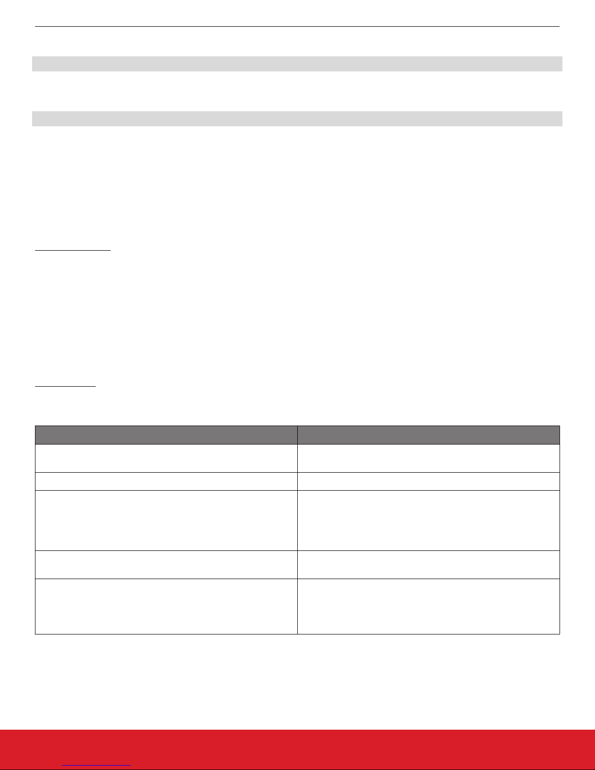
7.5 Cluster Support
This section details clusters that were implemented as part of this project.
Cluster Name Cluster Hex Value
Basic 0x0000
Identify 0x0003
On/Of 0x0006
Over The Air Boot Loading 0x0019
Illumination Measurement 0x0400
Temperature Measurement 0x0402
Relative Humidity Measurement 0x0405
Electrical Measurement 0x0B04
Diagnostics 0x0B05
Simple Metering 0x0702
Configuration Cluster 0xFC01
Firmware
Details about these clusters are provided in the Appbuilder ZCL clusters configuration tab within Simplicity Studio.
7.6 Command Line Interface Support
In addition to General CLI the following CLI command summaries are supported. Details about these command line interface features
are provided in the Appbuilder Printing and CLI tab within Simplicity Studio.
• Address Table
• Connection Manager
• Counters
• EEPROM
• EZ-Mode Commissioning
• Electrical Measurement Server commands
• Identify
• Illuminance Measurement Server commands
• Manufacturing Library
• Manufacturing Library CLI
• OTA Bootload
• OTA Client
• OTA Simple Storage EEPROM
• OTA Storage Common
• Relative Humidity Measurement Server commands
• Reporting
• Simple Metering Server
• Temperature Measurement Server commands
silabs.com | Smart. Connected. Energy-friendly. Rev. 0.1 | 12
Page 14

®
UG171: ZigBee
Smart Outlet Reference Design (RD-0051-0201) Kit User's Guide
Firmware
7.7 Included Plugin Options
Numerous plugins are available from the EmberZNET PRO stack. Notable ones are described in this section, along with their set options.
Manufacturing Library CLI
To assist with the manufacturing process, the occupancy sensor reference designs include the manufacturing library as well as the
manufacturing library CLI commands. On the factory floor, a unit that has been programmed with these images may be used to also
make radio measurements.
Theory of Operation
The purpose of the manufacturing library CLI plugin (or mfg-lib CLI plugin for short) is to allow access to commands that will put the
radio into test mode so that the radio modules can be tested at manufacturing time with the final bulb firmware images.
CLI Commands
Table 7.1. Commands for the Manufacturing Library
CLI Command Notes
plugin mfglib mfgenable <0|1> Set the token to pause plugin from scanning for channels to allow
for starting the manufacturing library before the stack operation
begins. 0 clears the token, 1 sets the token. The effect of setting
the token is that you will have 10 seconds after the next power-up
to preempt the stack from resuming normal operation and start
the mfglib.
plugin mfglib start <0|1> Starts the manufacturing library, which will prevent network activi-
ty as well as enable the rest of the manufacturing library commands. The argument dictates whether or not to track incoming
messages and provide receiver statistics on the incoming packets.
plugin mfglib stop Stops the manufacturing library
plugin mfglib set-channel <channel> Set the radio to the specified channel. Note: channel must be be-
teween 11 and 26 inclusive
plugin mfglib set-power <power> <mode> Sets the radio power to be used for manufacturing library transmit
commands. The mode, enables or disables boost mode for the
EM35x series of chips.
plugin mfglib stream <start|stop>
plugin mfglib tone <start|stop>
Note: There are additional CLI commands for use with the manufacturing library plugin. They can be explored by typing the command
"plugin mfglib " and seeing a list of valid commands. Above we are detailing the commands that are most commonly useful to an occupancy sensor reference design during the manufacturing process.
As an example in using these commands, here is the procedure for starting the manufacturing library:
1. Connect to the reference design and issue the mfgenable command: "plugin mfglib mfgenable 1”
2. Power cycle the reference design.
3. Within 10 seconds of power cycle, issue the start command “plugin mfglib start 0”
At this point, any of the manufacturing library commands can be safely executed without interference from the networking stack.
For example to take measurements on a modulated tone on channel 15 at a power of 20, issue the following commands:
plugin mfglib set-channel 15
plugin mfglib set-power 20 0
plugin mfglib stream start
silabs.com | Smart. Connected. Energy-friendly. Rev. 0.1 | 13
Page 15
UG171: ZigBee® Smart Outlet Reference Design (RD-0051-0201) Kit User's Guide
Firmware
At this time, take your measurements.
plugin mfglib stream stop
When the manufacturing tests are completed, it is important that you disable the manufacturing library delay at bootup with the following
command:
plugin mfglib mfgenable 0
It is not necessary to issue the manufacturing library stop command unless you wish to initiate normal networking activity without a
power cycle as the manufacturing library operation will be reset at the next power cycle.
Manufacturing Library OTA
This plugin implements the manufacturing library custom cluster from Silicon Labs. It provides a means, through radio messages, to put
the device into RF testing mode. In the past, enabling such features on a device required the user to physically alter the device (by
cutting the case, adding a connector, and connecting to a ribbon cable). For some tests, this is practically impossible. For others, it will
alter the results of the test (such as for FCC tests). To overcome these issues, Silicon Labs developed a way to invoke the manufacturing library commands using radio commands.
Theory of operation
Silicon Laboratories has created a custom ZigBee cluster that provides RF commands for the purpose of putting the device receiving
the commands into manufacturing test mode. Specifically, it can force the device to transmit an unmodulated tone, transmit a modulated tone, or receive packets for a short time to check the TX or RX path of the device in the field.
First, the user must obtain a gateway that supports this functionality. Our HaGatewayReference application supports the MFGLIB Cluster, although it is possible to use our development environment to create such a gateway.
After the gateway creates the network and the lighting reference design joins the network, the gateway can send commands to the
reference design to tell it which RF test to perform and which parameters to use, such as channel and TX power. Each of the RF commands also includes a timeout parameter, which sets the amount of time (in milliseconds) to enable the command. Using a timeout
parameter of 0 means that the device will remain in the specified RF test until the next device power cycle.
CLI Commands
Table 7.2. Manufacturing Library Over the Air Commands
OTA Command Notes
zcl mfg-code 0x1002 Sets the manufacturing code to 0x1002, which is the Silicon Labs
code used for these custom clusters.
zcl mfg-code 0 Unsets the manufacturing code.
zcl mfglib rx-mode <channel> <power> <time> Put the device into RX mode. Note: when in RX mode, the device
under test will keep track of the number of packets received, the
RSSI and the LQI of the first packet received. It is recommended
to use a non-zero timeout as these parameters are stored in volatile memory and will be reset at power cycle.
zcl mfglib stream <channel> <power> <time> Set the radio to transmit a modulated carrier. Note: the carrier will
be modulated with a random stream of characters.
zcl mfglib tone <channel> <power> <time> Set the radio to transmit a modulated carrier.
silabs.com | Smart. Connected. Energy-friendly. Rev. 0.1 | 14
Note: The carrier will be modulated with a random stream of characters.
Page 16

UG171: ZigBee® Smart Outlet Reference Design (RD-0051-0201) Kit User's Guide
Firmware
Here is an example of the commands used to command the reference design to transmit a modulated carrier at channel 15 with a power of 13 dBm until the next device power cycle.
Note:
It is assumed the gateway already created a network and that the reference design has joined this network with device ID 0x1234:
zcl mfg-code 0x1002
zcl mfglib-stream 15 13 0
send 0x1234 1 1
silabs.com | Smart. Connected. Energy-friendly. Rev. 0.1 | 15
Page 17

UG171: ZigBee® Smart Outlet Reference Design (RD-0051-0201) Kit User's Guide
Ecosystem Considerations
8. Ecosystem Considerations
In this reference design the firmware examples are ZigBee HA certifiable. As such, they should work with any of the ZigBee-certified
Home Automation gateways in the market. However, each gateway may have some individual requirements beyond the ZigBee Home
Automation requirements. Contact the individual gateway ecosystem provider for support in getting your device onto their ecosystem,
as several of these ecosystem providers have developer websites and communities to facilitate the effort.
In our testing, we have discovered that many gateway manufacturers require an end device to support two optional attributes in the
Basic cluster: manufacturer name and model identifier. While our reference designs have values for these attributes that are reflective
of the Silicon Laboratories reference design work, it is expected that each customer would customize these attributes for their own
product.
In our testing, we have also discovered that a few of the gateway manufacturers use the manufacturer name and model identifier
(among other things) to implement a white list. A white list is a list of approved devices that the gateway will allow onto its network. If
your device is not on the white list, it will not be allowed to join the network. For these gateways, you will need to contact the gateway
platform provider directly to inquire how to add your manufacturer name and model identifier to their gateway's white list.
silabs.com | Smart. Connected. Energy-friendly. Rev. 0.1 | 16
Page 18

UG171: ZigBee® Smart Outlet Reference Design (RD-0051-0201) Kit User's Guide
Engineering Tests
9. Engineering Tests
This reference design completed the following product testing for pre-certification purposes:
• ZigBee Home Automation (HA) v1.2
• FCC Emissions
• Antenna Radiation Patterns
• Underwriter's Laboratory (UL)
9.1 ZigBee Home Automation HA v1.2
The outlet reference design went through a preliminary HA 1.2 testing to verify compliance with the ZigBee standard.
9.2 FCC Emissions Testing
This design went through a preliminary FCC pre-scan testing to verify compliance with FCC Part 15 restrictions. Such testing is done to
ensure customers are given a design that can pass FCC tests. FCC compliance does not transfer to modules built according to this
reference design, even if the design is copied exactly.
9.3 Antenna Radiation Patterns
This design went through a series of tests to verify the efficiency of the antenna design. This is important to ensure as close to isotropic
radiation as possible.
9.4 Underwriter's Laboratory
This design went through a UL review. Of note is that while the internal power supply is rated to 240 VAC, the North American plug is
rated only for 120 VAC.
silabs.com | Smart. Connected. Energy-friendly. Rev. 0.1 | 17
Page 19

®
UG171: ZigBee
Smart Outlet Reference Design (RD-0051-0201) Kit User's Guide
Manufacturing Tests
10. Manufacturing Tests
This section describes how a user can develop a low-cost manufacturing test methodology in order to test products that utilize this reference design. Recommended test equipment and test procedures will also be outlined in this section.
10.1 Test Coverage
By following these guidelines, the following items will be tested and verified for functionality:
• RF TX/RX performance
• Power relay control functionality
• Current consumption
• Energy monitoring functionality
• Temperature functionality
• Humidity functionality
• Ambient light functionality
• Common ZigBee operations
• Frequency offset (with optional spectrum analyzer)
10.2 Test Equipment List
The test system is composed of the following components:
• Desktop PC
• RF Shielded Box
• Isolated AC Mains power supply
• 2x WSTK with debug adapter board
• Golden Node (Silicon Labs ZigBee coordinator device)
• Spectrum Analyzer (Agilent E4407B)
• Device Under Test (DUT)
10.3 Test System Diagram
Figure 10.1. Test System Diagram
silabs.com | Smart. Connected. Energy-friendly. Rev. 0.1 | 18
Page 20

UG171: ZigBee® Smart Outlet Reference Design (RD-0051-0201) Kit User's Guide
Manufacturing Tests
10.4 Test System Connection Procedure
Wire the system as indicated above. All WSTK adapters will be connected to the PC through USB. One adapter will connect to the
DUT, to both reprogram and interact with the DUT, whereas the second adapter will connect to the Golden Node for testing network
functionality. The adapters connected to the DUT should never be turned off. Instead, the DUT will be powered from the isolated Power
Supply for live current measurements.
Within the shielded box the only items protruding inward should be the connectors linked to the DUT, the connectors for 50 Ω antennas.
If desired, a spectrum analyzer may be procured and integrated into the system to measure frequency offset.
10.5 Configuring the WSTKs
For this setup, the PC will communicate to the WSTK with a serial connection. The WSTK will enumerate as a “COM Port” device when
connected to the PC via USB without any additional setup.
10.6 Communicating with Targets
For testing purposes, the NodeTest firmware image will be used on the target DUT. The PC will communicate with the DUT’s UART
interface through the WSTK’s COM port. Use a serial connection tool, such as PuTTY, to start a serial console connection to the
WSTK’s enumerated COM port with the following settings:
• Speed (baud): 115200
• Hardware flow control: enabled
• Data bits: 8
• Parity: none
• Stop bits: 1
Once connected, pressing Enter or sending a “\n” character will result in a prompt ending with a “>” character. Type “help” then press
Enter to display a list of available test functions in Test firmware.
silabs.com | Smart. Connected. Energy-friendly. Rev. 0.1 | 19
Page 21

Smart.
Connected.
Energy-Friendly.
Products
www.silabs.com/products
Disclaimer
Silicon Labs intends to provide customers with the latest, accurate, and in-depth documentation of all peripherals and modules available for system and software implementers using or
intending to use the Silicon Labs products. Characterization data, available modules and peripherals, memory sizes and memory addresses refer to each specific device, and "Typical"
parameters provided can and do vary in different applications. Application examples described herein are for illustrative purposes only. Silicon Labs reserves the right to make changes
without further notice and limitation to product information, specifications, and descriptions herein, and does not give warranties as to the accuracy or completeness of the included
information. Silicon Labs shall have no liability for the consequences of use of the information supplied herein. This document does not imply or express copyright licenses granted
hereunder to design or fabricate any integrated circuits. The products are not designed or authorized to be used within any Life Support System without the specific written consent of
Silicon Labs. A "Life Support System" is any product or system intended to support or sustain life and/or health, which, if it fails, can be reasonably expected to result in significant
personal injury or death. Silicon Labs products are not designed or authorized for military applications. Silicon Labs products shall under no circumstances be used in weapons of mass
destruction including (but not limited to) nuclear, biological or chemical weapons, or missiles capable of delivering such weapons.
Trademark Information
Silicon Laboratories Inc.® , Silicon Laboratories®, Silicon Labs®, SiLabs® and the Silicon Labs logo®, Bluegiga®, Bluegiga Logo®, Clockbuilder®, CMEMS®, DSPLL®, EFM®,
EFM32®, EFR, Ember®, Energy Micro, Energy Micro logo and combinations thereof, "the world’s most energy friendly microcontrollers", Ember®, EZLink®, EZRadio®, EZRadioPRO®,
Gecko®, ISOmodem®, Precision32®, ProSLIC®, Simplicity Studio®, SiPHY®, Telegesis, the Telegesis Logo®, USBXpress® and others are trademarks or registered trademarks of
Silicon Labs. ARM, CORTEX, Cortex-M3 and THUMB are trademarks or registered trademarks of ARM Holdings. Keil is a registered trademark of ARM Limited. All other products or
brand names mentioned herein are trademarks of their respective holders.
Silicon Laboratories Inc.
400 West Cesar Chavez
Austin, TX 78701
USA
Quality
www.silabs.com/quality
Support and Community
community.silabs.com
http://www.silabs.com
 Loading...