

Page 1

USB-MSD-RD
USB MASS STORAGE DEVICE REFERENCE DESIGN KIT USER’S GUIDE
1. Kit Contents
CF, SD, MMC Memory Expansion Board (AB5)
256 MB SD Card
Straight DB9 serial cable (RS-232 cable)
Quick-start Guide
Reference Design Kit CD-ROM containing the following items:
USB Mass Storage Device Reference Design Programmer's Guide (AN282), and associated software (AN282SW.zip)
Keil Software 8051 Development Tools (evaluation assembler, 2 kB limited compiler, and linker)
All C8051F340 and USB MSD related documentation in PDF format
2. Requirements
The USB MSD Reference Design Kit has been designed for use with a C8051F340DK Development Kit. The
development kit can be purchased separately from Silicon Laboratories (www.silabs.com). The following are the
requirements to use this Reference Design Kit as described in this User's Guide.
C8051F340DK Development Kit (contents shown below):
C8051F340-TB Target Board
USB Debug Adapter
6' USB Cable
AC to DC Power Adapter
PC with the following features:
Operating system: Windows 2000/XP/Server2003
Available ports: One serial port (RS232) and one USB port
Note: A full version of the Keil tool chain is required in order to modify and recompile the code provided with this reference
design because the code size is greater than evaluation tool chain's code size limits. No tool chain is required for the
demonstration or for debugging because an object file (*.OMF) is provided with the reference design.
3. USB Mass Storage Device Reference Design Kit Overview
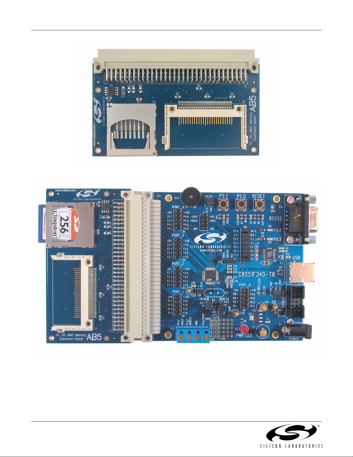
The USB Mass Storage Device (MSD) Reference Design Kit includes the AB5 Expansion Board (shown in
Figure 1) that can be connected directly to the expansion connector of a C8051F340-TB Target Board. The
connected setup with a SD memory card is shown in Figure 2. This hardware and the included 'F340 firmware fully
demonstrate how an application can benefit from implementing the USB MSD device class. The firmware is
described in Section “4. USB MSD RD Firmware”. Step-by-step demonstration instructions are provided in Section
“5. USB MSD Reference Design Kit Demonstration”. Detailed descriptions of the components and API functions
are included in “AN282: USB Mass Storage Device Reference Design Programmer's Guide". The board hardware
is described in sections 6, 7, and 8.
Rev. 0.1 5/06 Copyright © 2006 by Silicon Laboratories USB-MSD-RD
Page 2
USB-MSD-RD
Figure 1. CF, SD, MMC Memory Expansion Board (AB5)
Note: The C8051F340-TB Target Board is not included with the USB-MSD-RD Kit.
Figure 2. C8051F340-TB connected to AB5 Expansion Board with SD Card
2 Rev. 0.1
Page 3

USB-MSD-RD
4. USB MSD RD Firmware
The USB MSD RD includes all the 'F340 firmware necessary to handle the following:
USB enumeration and standard requests
MSD class requests
SCSI command set
Media access - SD, MMC and CompactFlash card formats
FAT16 file system support
Also included is an example application that can perform the following tasks:
Present an interactive command shell via the UART
Measure temperature using the on-chip temperature sensor and ADC
Monitor the state of the two push-button switches on the target board
Log the temperature and button state information to log files in the memory card
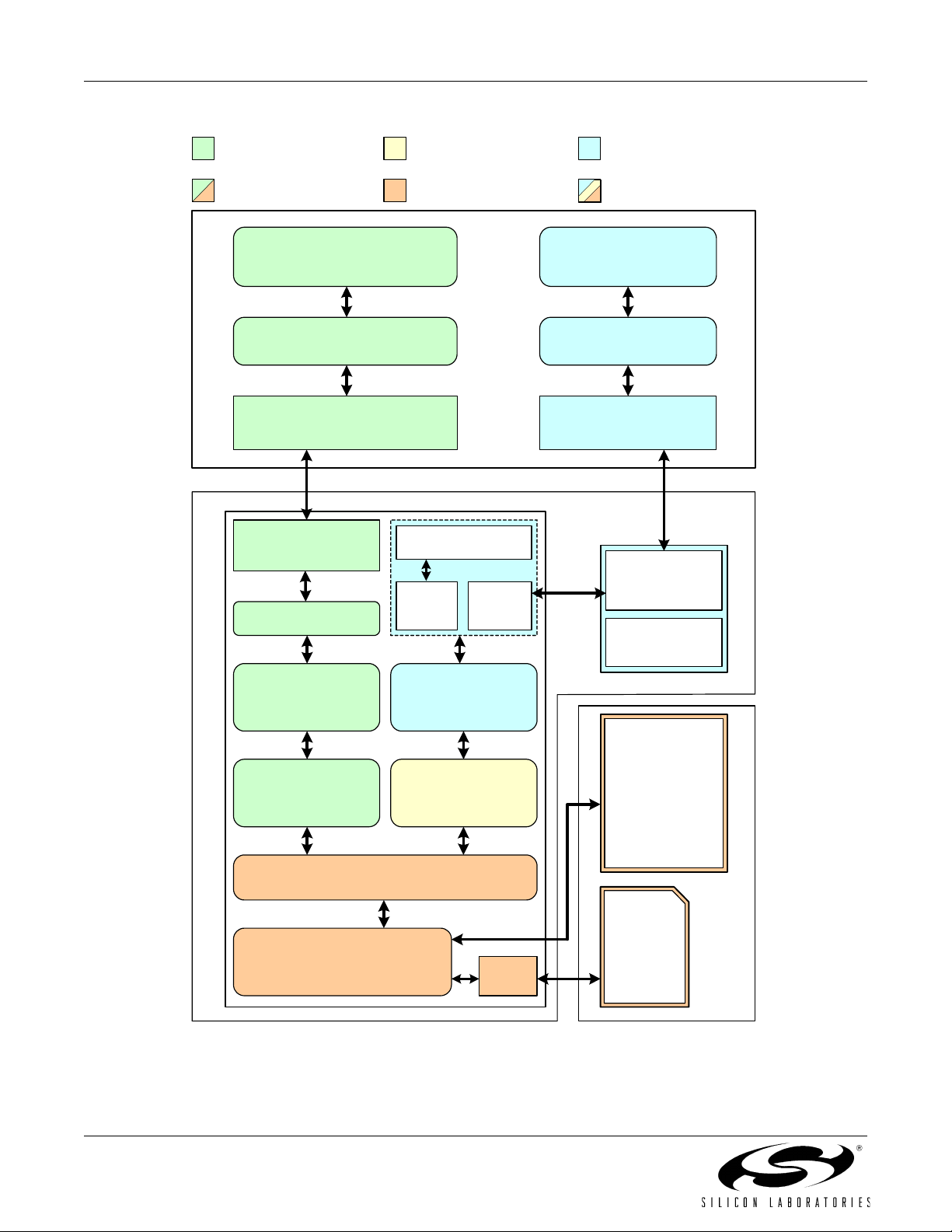
The USB MSD RD System Architecture shown in Figure 3 gives an overview of the various components that
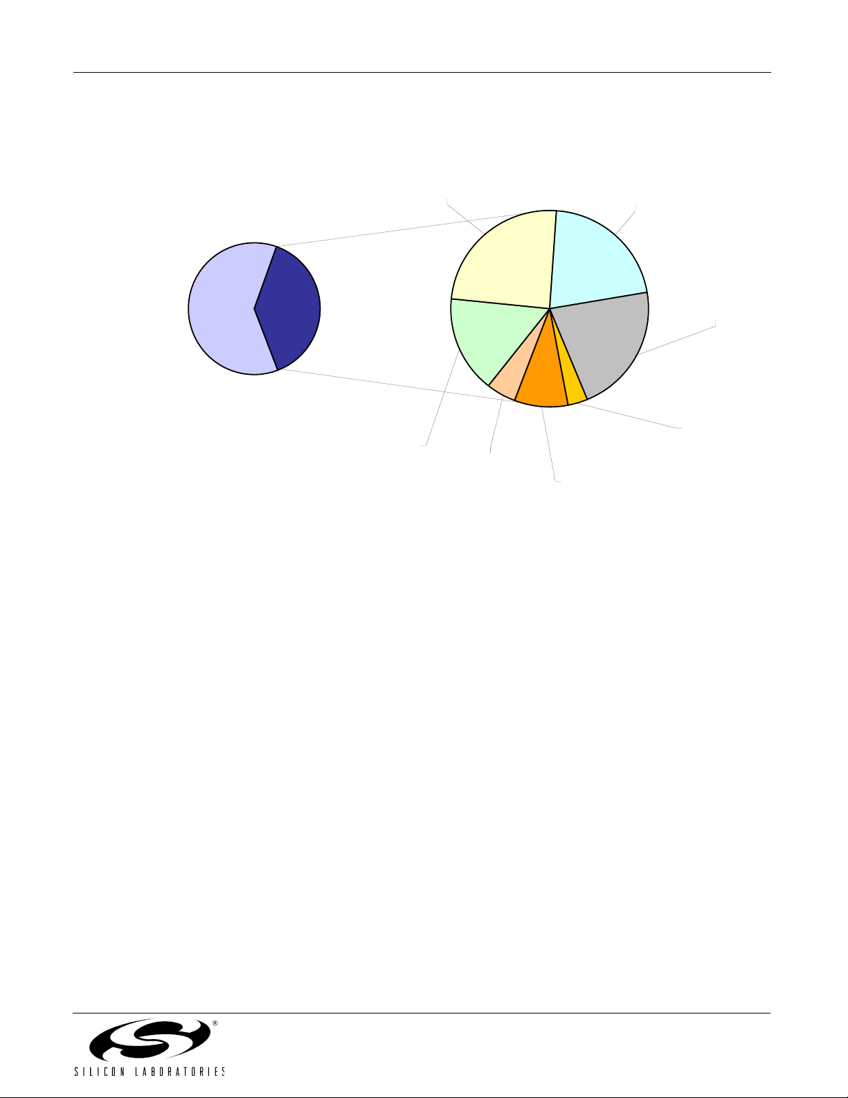
constitute the USB MSD RD firmware. The code space usage chart in Figure 4 shows the amount of code space
used by the firmware components. Detailed descriptions of the components and API functions are included in
“AN282: USB Mass Storage Device Reference Design Programmer's Guide".
To implement your own application based on this USB MSD Reference Design, you can customize the blocks
labeled 'Application', 'Other HW Peripherals', and 'App. Specific Hardware' (all shown in blue in Figure 3). Source
code for all the other firmware blocks is also provided, but typically there is no need to customize these blocks.
Rev. 0.1 3
Page 4
USB-MSD-RD
Components used only
for USB MSD Data Flow
USB MSD Data Flow
Windows Explorer or
Other Application
File system API serving
the Example App.
Shared media access
components
Example App. components
that can be customized
Example App. Data Flow
HyperTerminal
Driver Stack Driver Stack
USB Host Controller RS232 Serial Port
PC
USB Function
Temp. Sensor
Controller
Transceiver
ADC
UART
USB
Mass Storage
Device
Example
Application
External HW Peripherals
RS232
Push
Buttons
SCSI
File System
Sector Server
C8051F340 USB Mixed Signal MCU
Media Access
C8051F340-TB Target Board
Figure 3. USB MSD RD System Architecture
4 Rev. 0.1
SPI
Compact
Flash
Memory
Card
SD /
MMC
Memory
Card
AB5 Memory
Expansion Board
Page 5
USB-MSD-RD
Available
Free Space
(39.1 kB)
62%
File System
Used
(23.9 kB)
38%
USB / MSD /
SCSI (3.9 kB)
6%
(5.9 kB)
9%
Sector Server
(1.1 kB)
2%
Example
Application
(5.1 kB)
8%
SD / MMC
Media Access
(2.1 kB)
3%
Compiler
Libraries /
Misc
(5.1 kB)
8%
CF Media
Access
(0.7 kB)
1%
Figure 4. USB MSD Firmware Code Space Usage on the C8051F340
Rev. 0.1 5
Page 6
USB-MSD-RD
5. USB MSD Reference Design Kit Demonstration
The following step-by-step demonstration will walk you through the various features and capabilities of this
reference design. There are three parts to this demonstration: Firmware Download, Example Application
Demonstration, and Mass Storage Device Demonstration.
Note: The demonstration instructions assume that a PC running Windows 2000/XP/Server2003 is being used.
5.1. Firmware Download
The steps in this section will guide you in downloading the USB MSD Reference Design firmware to the
C8051F340-TB target board.
1. Follow the 'Software Setup' instructions in the C8051F340DK User's Guide to install the Silicon Laboratories
IDE. This document is available at the following web page: http://www.silabs.com/tgwWebApp/public/
web_content/products/Microcontrollers/USB/en/C8051F340DK.htm.
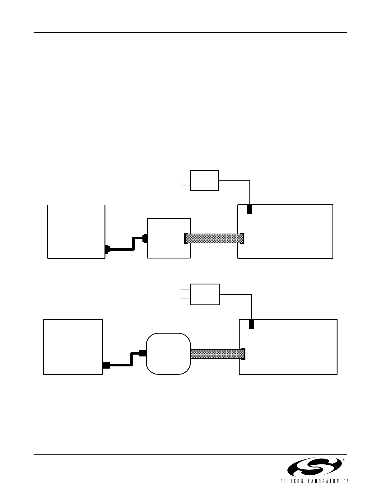
2. Depending on which type of debug adapter you have, set up the hardware as shown in one of the two diagrams
below (Figure 5, Figure 6). Consult the C8051F340DK User's Guide for detailed instructions.
AC/DC
Adapter
PC
Serial Port
Serial
Cable
Serial
Adapter
Ribbon
Cable
Target
Board
Figure 5. Hardware Setup using a Serial Debug Adapter
AC/DC
Adapter
PC
USB Port
USB
Cable
USB
Debug
Adapter
Ribbon Cable
Target Board
Figure 6. Hardware Setup using a USB Debug Adapter
3. Launch the Silicon Labs IDE using the icon from your Start Menu: 'Start Menu → Programs → Silicon
Laboratories
4. Before connecting to the target device, several connection options may need to be set. Open the 'Connection
Options' window by selecting 'Options
was included with the kit in the "Serial Adapter" section. Next, the correct "Debug Interface" must be selected.
C8051F34x family devices use the Silicon Labs 2-wire (C2) debug interface. Once these selections are made,
click the OK button to close the window.
→ Silicon Laboratories IDE'
→ Connection Options...' in the IDE menu. First, select the adapter that
6 Rev. 0.1
Page 7

USB-MSD-RD
5. Click the 'Connect' button in the toolbar or select 'Debug → Connect' from the menu to connect to the device.
You will see the text "Target: C8051F340" in the status bar of the IDE if the connection was successful.
6. Choose the 'Project
button and select the USB MSD RD firmware pre-linked OMF file from this path:
C:\Silabs\MCU\USB_MassStorageDevice_RD\Firmware\F34x_MSD.OMF
7. Click the 'Download' button to download this firmware to the 'F340 device. You will see the text "Download
successful" in the Build window if the firmware was downloaded successfully.
8. Disconnect the dc power adapter and the ribbon cable from the target board.
5.2. Example Application Demonstration
The Example Application demonstrates how the reference design can be used as an independent embedded
system while it is not connected to a PC via USB. In this configuration, the embedded system is able to perform
various tasks based on user commands via a UART-based interactive command shell.
5.2.1. PC Software Setup
On the PC, set up HyperTerminal to use the COM port at 115200 baud, 8-N-1, and no flow control as shown in
Figure 7. Detailed setup instructions are shown below.
1. Launch HyperTerminal from your Start Menu: 'Start Menu
HyperTerminal'.
2. Type any name for the new connection, and click OK.
3. In the 'Connect using:' drop-down list, Choose 'COM1', or if you have multiple COM ports, choose the one you
want to use.
4. Set up the COM1 Properties dialog as shown in Figure 7, and click OK.
→ Download Object File…' option. This shows a 'Download' dialog. Click the 'Browse'
→ Programs → Accessories → Communications →
Figure 7. Example Application - HyperTerminal Settings
Rev. 0.1 7
Page 8

USB-MSD-RD
5.2.2. Hardware Setup
1. Connect the C8051F340-TB target board connector J13 to the AB5 expansion board connector J1.
2. Insert the SD card provided with the reference design kit into the SD card slot (M2) in the expansion board.
3. Connect a straight DB9 serial cable (RS-232 cable) between the PC's serial port and C8051F340-TB.
4. Make sure that the jumpers on the 'F340 TB are as shown in Figure 8.
5. Apply power to the target board using a dc power adapter.
AB5 Expansion Board C8051F340-TB Target Board
RESET
P2.0
P2.1
J16
SW3 SW2 SW1
J12
J8
C8051F340-TB
C8051F340-TB
U1
J10
J2
J7
D2
PWR
RS232
RS232
D4
D3
P3
J19
DB9
P4
P4
Serial
Cable
to PC
3
USB
USB
P3
DEBUG
J9
4
P1
AC-to-DC
Power Adapter
SD
Card
2
SILICON LABORATORIES
SD / MMC
Card Slot
M2
CompactFlash
Card Slot
M1
AB5 (CF, SD, MMC Memory
Expansion Board)
J1
1
J13
J13
R10
J6
J5
J4
J3
J17
J1
SILICON LABORATORIES
340
J15
J11
P2
Figure 8. Demonstration Connections
5.2.3. Interacting with the Example Application
1. A command interpreter shell is presented via HyperTerminal. Use this to interact with the device firmware to
record a temperature log. Follow the steps below referring to screenshot in Figure 9.
Note: If the text "USB Active; UART Disabled" is displayed even when a USB cable is not plugged into the USB connector on
the board, it most likely is because of error(s) in jumper settings. See Figure 8 for the correct jumper settings.
a. Type "calibrate 25" to calibrate the device to room temperature (25 ºC).
b. Type "templog temp.txt" to initiate temperature logging to a file that is updated every second. This is an example of
periodic logging, where the interval between logs is known in advance. The 'F340 ADC0 measures the temperature
using the on-chip temperature sensor, which is then logged to a file.
c. Wait for a few seconds to collect some temperature data in the file.
d. Type "templog" to stop the log.
e. Type "type temp.txt" to view the contents of the log file.
8 Rev. 0.1
Page 9

USB-MSD-RD
Figure 9. Example Application - Temperature logging
Rev. 0.1 9
Page 10

USB-MSD-RD
2. Continue to use the command interpreter shell to log press/release events for the buttons P2.0 and P2.1 on the
C8051F340 target board. Follow the steps below and also refer to Figure 10.
a. Type "log button.txt" to initiate button press/release logging to a file that is updated every time a button press or release
event occurs. This is an example of asynchronous logging, where the interval between logs is not known in advance. The
events are logged with the time value in milliseconds that shows the time since the last event.
b. Press buttons labeled "P2.0" and "P2.1" repeatedly for a few times in any order you wish.
c. Type "log" to stop the log.
d. Type "type button.txt" to view the contents of the log file.
Figure 10. Example Application - Button state logging
3. In addition to the above commands, you can also try other commands supported by the command interpreter
shell. An index of all commands supported by the example application is available in “Appendix A—Command
Interpreter Shell Reference”.
10 Rev. 0.1
Page 11

USB-MSD-RD
5.3. Mass Storage Device Demonstration
This demonstrates the 'F340 device firmware support for the standard USB Mass Storage Device class. The
HyperTerminal interactive command shell is deactivated whenever the device is plugged into the PC via a USB
cable. This is to protect against simultaneous access of the file system by the PC and the example application.
1. Connect a USB cable between the PC and the C8051F340-TB target board.
2. The operating system will detect the new hardware, recognize it as a standard USB Mass Storage Device, and
install appropriate drivers. There should be no need for any user interaction during this phase. At the end of this
process, you will see three entries in Device Manager, and you should also see a Removable Disk in Windows
Explorer. See Figures 11 and 12.
Figure 11. USB Mass Storage Device - Device Manager
Rev. 0.1 11
Page 12

USB-MSD-RD
Figure 12. USB Mass Storage Device - Windows Explorer
3. The files created during the previous example application demonstration will be visible. Files can be viewed,
added, deleted, copied or moved using Windows Explorer.
4. To disconnect the device, click on the icon with the green arrow in the system tray and select "Safely Remove
USB Mass Storage Device". See Figure 13. You can unplug the USB cable from the C8051F340-TB Target
Board after you see a message informing you that it is safe to do so. Unplugging the USB cable will restore
control to the HyperTerminal-based command interpreter shell.
Figure 13. USB Mass Storage Device - Safe Device Removal
12 Rev. 0.1
Page 13

USB-MSD-RD
6. CF, MMC, SD Memory Expansion Board (AB5)
The CF, MMC, SD Memory Expansion Board contains a SD/MMC card slot, a CompactFlash card slot, and a
power gating FET that allows control of power to the expansion board via software. The pin connections are shown
in Table 1. The board schematic is shown in Figure 14.
Table 1. CF, SD, MMC Memory Expansion Board Pin Connections
Signal
Name
POWER A1 +3VD Digital Power
GND B1 GND Digital Ground
ADD0 B16 P3.5 CF Address bit 0
ADD1 A16 P3.6 CF Address bit 1
ADD2 C15 P3.7 CF Address bit 2
DA0 B15 P4.0 CF Data bit 0
DA1 A15 P4.1 CF Data bit 1
DA2 C14 P4.2 CF Data bit 2
DA3 B14 P4.3 CF Data bit 3
DA4 A14 P4.4 CF Data bit 4
DA5 C13 P4.5 CF Data bit 5
DA6 B13 P4.6 CF Data bit 6
DA7 A13 P4.7 CF Data bit 7
SCK C12 P0.0 SD/MMC SPI Clock
Connector
Pin
C8051F340-TB
Connection
Description
MISO B12 P0.1 SD/MMC SPI Master In, Slave Out
MOSI A12 P0.2 SD/MMC SPI Master Out, Slave In
NSS C11 P0.3 SD/MMC SPI Slave Select
OE A23 P1.1 CF Output Enable
CE1 C22 P1.2 CF Card Enable
CD1 B22 P1.3 CF Card Detect
RDY A22 P1.4 CF Ready Signal
RESET C21 P1.0 CF Reset Signal
WE B21 P1.6 CF Write Enable
PWR_ON A21 P1.7 Expansion board global power control
Rev. 0.1 13
Page 14

USB-MSD-RD
7. Schematic
CS1DI
VDD4SCLK
M2
2
VCC
MOSI
NSS
C2
100n
GND
R5
4k7
R4
4k7
VCC
R3
4k7
DA1
13
D0021D0122D02
VCC
VCC
C1
100n
VCC
GND
M1
20
38
ADD1
ADD0 DA0
DO7RSV8RSV
5
MISO
SCK
DA3
DA4
DA2
23
D032D043D054D065D07
ADD2
9
Resistors R3..R5 are optional
DA5
DA6
VSS
VSS
SDE915B
3
6
GND
R2
10k
R1
10k
VCCWE
DA7
6
49
D0847D0948D10
A10
A0910A0811A07
A0614A0515A0416A0317A0218A0119A00
8
12
D1127D1228D1329D1430D15
RESET
41
RESET
GND
VCC
CE1
7
31
OE
WP
CSEL
9
24
39
OE
R6
10k
32
CE1
CE2
IORD34IOWR35WE36READY
CD1
26
33
40
VS1
VS2
CD225CD1
WAIT42INPACK43REG
37
44
VCC
RDY
GND
1
46
GND
BVD245BVD1
GND
CARD-CF50C10
50
GND
DA2
DA5DA6DA7
ADD2
NSS
C1C2C3C4C5C6C7C8C9
J1C
GND
B1B2B3B4B5B6B7B8B9
J1B
C3
1u
VCC
T1
IRF7204
R7
100k
POWER
A1A2A3A4A5A6A7A8A9
J1A
GND
C10
C11
C12
C13
C14
C15
C16
MISOMOSI SCK
DA0
DA3DA4
ADD0ADD1
B10
B11
B12
B13
B14
B15
B16
DA1
A10
A11
A12
A13
A14
A15
A16
14 Rev. 0.1
CE1CD1RDY
RESET
C17
C18
C19
C20
C21
C22
C23
C24
C25
C26
C27
C28
C29
C30
C31
C32
DIN41612C96P
WE
B17
B18
B19
B20
B21
B22
B23
B24
B25
B26
B27
B28
B29
B30
B31
B32
DIN41612C96P
Figure 14. CF, MMC, SD Memory Expansion Board (AB5) - Schematic
OE
PWR_ON
A17
A18
A19
A20
A21
A22
A23
A24
A25
A26
A27
A28
A29
A30
A31
A32
DIN41612C96P
Page 15

USB-MSD-RD
Footprint
CF50C10
SDE915B
Kingston
LF
MMCE715B-
IRF7204PBF Digi-Key IRF7204PBF-ND SO-8
Rectifier
Manufacturer Manufacturer Part # Supplier Supplier Part # PCB
Dielectric Qty per
Description Value/Type Tol era nce Vol tag e
unit
/Power
10k 5% 1/8W 2 Yageo America RC0805JR-0710KL Digi-Key 311-10KARCT-ND 0805
5% 0805 SMD
100k 5% 1/8W 1 Yageo America RC0805JR-07100KL Digi-Key 311-100KARCT-ND 0805
1/8W 5% 0805 SMD
100n 10% 50V X7R 2 Yageo America CC0805KRX7R9BB104 Digi-Key 311-1140-1-ND 0805
1 Maritex CARD-
1u 10% 16V X7R 1 Yageo America CC1206KKX7R7BB105 Digi-Key 311-1181-1-ND 1206
MMCE715B-LF
CERAMIC X7R 0805
CERAMIC X7R 1206
256MB 1 Secure Digital 256MB
IRF7204 1 International
5.3A 8-SOIC
DIGITAL
256MB SECURE
Designator
10 R1 R2 RES 10K OHM 1/8W
20 R7 RES 100K OHM
8. Bill of Materials
Pos. Reference
30 C1 C2 CAP .10UF 50V
40 C3 CAP 1.0UF 16V
50 J1 Connector DIN41612C96P 1 Maritex DIN41612C96P;LF DIN41612C96P
60 M1 CF Card Connector CARD-CF50C10 1 Maritex CARD-CF50C10;LF CARD-
70 M2 SD Card Connector CARD-
80 T1 MOSFET P-CH 20V
90 Memory Card MEMORY CARD
DO NOT POPULATE
1000 R3 R4 R5 4k7
1010
Rev. 0.1 15
Page 16

USB-MSD-RD
APPENDIX A—COMMAND INTERPRETER SHELL REFERENCE
Command Interpreter Shell - Communication Parameters
Baud rate: 115200 bps
Data format: 8 data bits, 1 stop bit, no parity
Flow control: None
Command Interpreter Shell - Supported Commands
The interactive command interpreter shell presented by the example application via the UART supports a set of
MS-DOS-like commands. Table 2 lists the supported commands along with explanations.
Table 2. Command Interpreter Shell - Supported Commands
Command Explanation
CLS Clear the screen.
DIR Show the contents of the current directory.
MD <dirname> Make “dirname”directory. If “dirname” is incorrect or already exists, an error message is
returned.
CD <dirname> Change to “dirname” directory. If “dirname” is incorrect or does not exist in the present
directory, an error message is returned.
RD <dirname> Remove “dirname” directory. If “dirname” is incorrect, an error message is returned.
IMPORTANT:
TYPE <filename> Show the ASCII contents of a file in the current directory.
DEL <filename> Delete a file in the current directory.
FORMAT Format the existing FAT16 partition. Note: This will not work properly if the existing file
system is of a format other than FAT16. See “Appendix B—Formatting a Memory Card”
for instructions on how to format a new disk.
S <nnnnn> Show the contents of the nnnnn-th 512-byte block. Calling “S” without a parameter will
print the valid range of sectors.
CHKDSK Show info about the formatting used.
CALIBRATE <val> Sets offset for temperature sensor. ‘val’ should be current ambient temperature in
degrees C.
TEMPLOG <filename> Start background logging of ambient temperature. The logging is appended at the end of
the specified file in the current directory. Calling “TEMPLOG” without a parameter will
stop current logging, if any, and close that file.
LOG <filename> Start background logging of the state of the two buttons (P2.1 and P2.2). The logging is
appended at the end of the specified file in the current directory. Calling “LOG” without a
parameter will stop current logging, if any, and close that file.
No check is done on “dirname” directory contents before removal.
16 Rev. 0.1
Page 17

USB-MSD-RD
Command Interpreter Shell - Notes
1. The commands are not case-sensitive.
2. Wild cards (*,? etc) are not supported by the shell.
3. Long file names are not supported by the shell. They are abbreviated to 8.3 format by removing unsupported
characters, truncating when longer than 8 characters, and adding a numbered suffix. This is done as described
in the following Microsoft Knowledge Base article: http://support.microsoft.com/?kbid=142982
Example: If two files named 'abcdefghi.txt' and 'abcdefghk.txt' are placed in the one folder when the device is in
PC mode, the "dir" command in Example Application mode will list them as 'abcdef~1.txt' and 'abcdef~2.txt',
respectively.
4. The 'dir' command shows the volume label as a separately entry, with the tag "<LABEL>" shown in the
extension column.
5. File creation/modification date and time stamps are not supported when the device is in Embedded System
Mode.
Rev. 0.1 17
Page 18

USB-MSD-RD
APPENDIX B—FORMATTING A MEMORY CARD
The USB MSD RD firmware supports the FAT16 file system. Memory cards formatted with other file systems
cannot be used with this firmware. If the disk is already formatted as FAT16, and you want to reformat the disk, you
can do so using the "FORMAT" command available through the Example Application's Command Interpreter Shell.
See “Appendix A—Command Interpreter Shell Reference” for details.
Formatting using Windows Explorer:
If the disk is formatted with a file system other than FAT16, or if you are not sure what file system is currently on the
disk, you can perform a new format on the disk using the "Format" command available in Windows Explorer.
WARNING: Using the Format command will erase all data from the target disk, and is irreversible.
Connect the system as described in Section “5.3. Mass Storage Device Demonstration”. After the device has
enumerated and shows up as a removable disk, open 'My Computer', right-click on the removable disk, and
choose 'Format'. In the following dialog, choose 'FAT' as the file system and click the 'START' button to start the
formatting process. Optionally, you can enter a volume label as well.
Limitations:
Memory card sizes should be greater than 16 MB, up to a maximum of 4 GB.
Windows formats memory card sizes up to 16 MB as FAT12, which is not supported by the USB MSD RD
firmware.
The FAT16 file system supports memory sizes up to 4 GB.
Troubleshooting:
If the memory card does not appear as a valid USB Mass Storage Device when connected, it is most likely
formatted in a way that is not readable by the firmware (for example, a custom digital camera format). In this case,
the card should be formatted using a dedicated memory card reader or other specialized device.
18 Rev. 0.1
Page 19

NOTES:
USB-MSD-RD
Rev. 0.1 19
Page 20

USB-MSD-RD
CONTACT INFORMATION
Silicon Laboratories Inc.
4635 Boston Lane
Austin, TX 78735
Tel: 1+(512) 416-8500
Fax: 1+(512) 416-9669
Toll Free: 1+(877) 444-3032
Email: productinfo@silabs.com
Internet: www.silabs.com
The information in this document is believed to be accurate in all respects at the time of publication but is subject to change without notice.
Silicon Laboratories assumes no responsibility for errors and omissions, and disclaims responsibility for any consequences resulting from
the use of information included herein. Additionally, Silicon Laboratories assumes no responsibility for the functioning of undescribed features
or parameters. Silicon Laboratories reserves the right to make changes without further notice. Silicon Laboratories makes no warranty, representation or guarantee regarding the suitability of its products for any particular purpose, nor does Silicon Laboratories assume any liability
arising out of the application or use of any product or circuit, and specifically disclaims any and all liability, including without limitation consequential or incidental damages. Silicon Laboratories products are not designed, intended, or authorized for use in applications intended to
support or sustain life, or for any other application in which the failure of the Silicon Laboratories product could create a situation where personal injury or death may occur. Should Buyer purchase or use Silicon Laboratories products for any such unintended or unauthorized application, Buyer shall indemnify and hold Silicon Laboratories harmless against all claims and damages.
Silicon Laboratories and Silicon Labs are trademarks of Silicon Laboratories Inc.
Other products or brandnames mentioned herein are trademarks or registered trademarks of their respective holders.
20 Rev. 0.1
 Loading...