

Page 1
UG233: USB Type-C Reference Design
User's Guide
The EFM8 USB Type-C Reference Design is intended to aid the
development of various USB Type-C applications and consists of
a development board, Simplicity Studio libraries, and example
code.
The board contains Power Delivery (PD) controllers, Billboard devices, and Alternate
Mode functionality.
KEY POINTS
• Describes the Type-C reference design
board
• Explains how to load the software
examples and begin evaluation and
development
• Discusses the power scenarios/options
related to the reference board
• Shows how to configure the Debug Serial
Terminal
• Shows the reference design board
schematics
silabs.com | Smart. Connected. Energy-friendly. Rev. 0.2
Page 2
UG233: USB Type-C Reference Design User's Guide
Introduction and Running the Demo
1. Introduction and Running the Demo
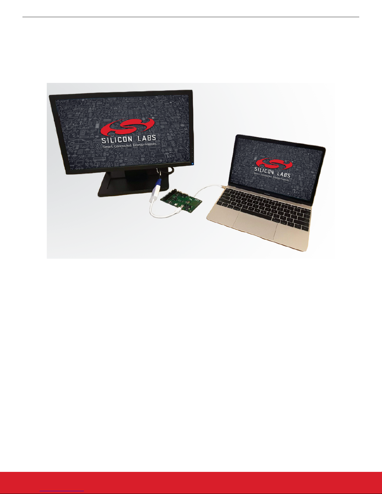
The USB Type-C Reference Design is intended to aid the development of various USB Type-C applications and consists of a development board, Simplicity Studio libraries, and example code. Out of the box, the board is configured as a DisplayPort alternate mode
video adapter. For a quick demo, simply plug the USB Type-C captive cable into a compatible host and a monitor cable into the mini
DisplayPort (mDP) receptacle. In the absence of a DisplayPort-capable monitor a video converter dongle, like the white VGA-to-mDP
shown in the image, can be used. However, in this case, J22 must be closed in order to power the external adapter.
Figure 1.1. Demo Setup
silabs.com | Smart. Connected. Energy-friendly. Rev. 0.2 | 1
Page 3

UG233: USB Type-C Reference Design User's Guide
Board Description
2. Board Description
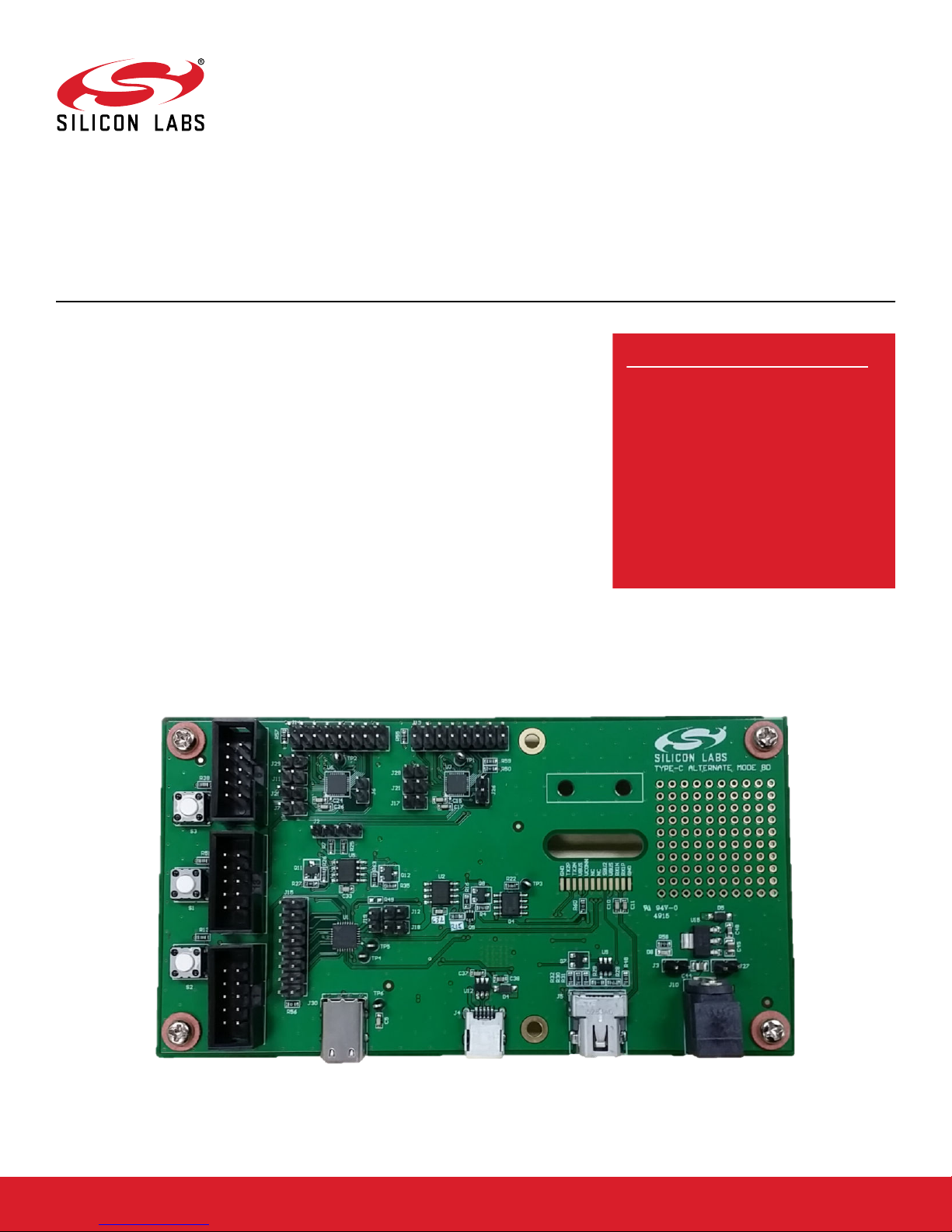
The Type-C reference design board is a platform for developing and evaluating hub and dongle Type-C solutions. The board contains
Power Delivery (PD) controllers, Billboard devices, and Alternate Mode functionality. The PD Controller is implemented with EFM8 Busy
Bee 3 (EFM8BB3) MCU, and takes advantage of the feature-rich peripherals available on-chip. The only necessary external circuits are
the CC lines voltage clamps for Dead-Battery, the slew rate control capacitors, and a Pull-Up (Rp) switch for Power Role SWAP function and DRP support. The board also contains a Billboard device implemented with the EFM8 Universal Bee 1 (EFM8UB1) MCU and
allows for Alternate Mode to be used and sent through the Type-C port. For debugging and communication purposes, a USB-to-Quad
UART Bridge Controller (CP2108) is used to print debug messages from all MCUs to a USB host serial terminal. Most of the available
GPIOs from each MCU are routed to pin headers for convenient interfacing with instrumentation and/or system-level integration. The
C2 debug interface for each MCU is also routed to headers so that individual firmware can be loaded onto each device.
silabs.com | Smart. Connected. Energy-friendly. Rev. 0.2 | 2
Page 4

UG233: USB Type-C Reference Design User's Guide
Board Description
Figure 2.1. Board Layout
Table 2.1. Board Component Map
Component Name Function
J26 Jumper Must be closed for proper operation.
J17 Jumper Alternate Mode PD controller MCU power supply monitoring jumper. Must be
closed for normal operation.
J12 Jumper Billboard device MCU power supply monitoring jumper. Must be closed for nor-
mal operation.
U3 EFM8BB3 USB Type-C DisplayPort Alternate Mode Power Delivery controller.
J8 HEADER_EC3 C2 programming interface connector for U3 MCU.
U1 EFM8UB1 USB Billboard class device.
J1 HEADER_EC3 C2 programming interface connector for U1 MCU.
U6 EFM8BB3 USB Type-C charging port Power Delivery controller.
J3 HEADER_EC3 C2 programming interface connector for U6 MCU.
J5 mDP Socket Mini DisplayPort socket.
J4 Mini USB Used for printing debug messages to a serial terminal.
J30 USB Type-C Receptacle Charging port connector. The socket is rated 3A max.
S1 Switch Reset push button switch for U3 MCU.
S2 Switch Reset push button switch for U1 MCU.
S3 Switch Reset push button switch for U6 MCU.
J2 Pins header I2C bus.
silabs.com | Smart. Connected. Energy-friendly. Rev. 0.2 | 3
Page 5

UG233: USB Type-C Reference Design User's Guide
Board Description
The following block diagram can be used to understand the main functions of the reference design and the connections between devices and plugs.
Figure 2.2. Functional Block Diagram Overview
silabs.com | Smart. Connected. Energy-friendly. Rev. 0.2 | 4
Page 6

UG233: USB Type-C Reference Design User's Guide
Evaluation and Development
3. Evaluation and Development
The Type-C reference design with all of the above-mentioned capabilities is available for free once a Software License Agreement has
been signed. After getting the demo to run, the next step is to load the software examples and source code to begin development.
1. Download and extract the Release folder from the provided reference design.
Figure 3.1. Reference Design Folder
2. Download and install Simplicity Studio from http://www.silabs.com/products/mcu/Pages/simplicity-studio.aspx.
3. Open the Simplicity Studio IDE and switch workspaces using the [File] → [Switch Workspace]. Locate the release folder that was
extracted in step one and select the top-level folder as the workspace.
4. Import the project by going to [File] → [Import] → [Simplicity Studio] → [MCU Project].
5. Locate the SLS directory under the reference design folder and select one of the projects to develop: ufp_dongle, knlexample, or
billboard.
6. Ensure that EFM8BB31F64G part is selected and click [Next].
7. The project is now imported and can build, run, or be altered to fit specific needs.
8. For development assistance and information on the programming interface please open [index.html] in the [doc] directory.
Each of the UC3 headers on the board connects the C2 interface of a specific device. The color-coded circles in the Figure 2.1 Board
Layout on page 3 show which header connects to which device. By using a debug adapter like this https://www.silabs.com/
products/mcu/Pages/USBDebug.aspx, the firmware developed in Simplicity Studio can be loaded onto the devices.
silabs.com | Smart. Connected. Energy-friendly. Rev. 0.2 | 5
Figure 3.2. UFP Dongle Project
Page 7

UG233: USB Type-C Reference Design User's Guide
4. Power
For developers’ convenience, the reference board supports a flexible powering scheme, as depicted in the following diagram:
Figure 4.1. Power Block Diagram
Power
Various power sources can co-exist due to the presence of separate diodes. Below are some power scenarios:
1. VCONN provides power from the USB-C host (DFP). No other power sources are needed for the functional mode.
Note: If a VGA to mDP dongle is used, VCONN alone may not be able to supply enough power.
2. EC3 debug adapter provides power while flashing/debugging the MCU in Simplicity Studio.
3. The board can be powered from the USB host which runs the Serial Terminal Application.
4. Standard 9 V wall adapter.
The 3.3 V voltage can be obtained from an external LDO (Max. 500 mA), or from the EFM8UB1 internal LDO (Max. 100 mA). The
following jumper settings are for evaluating different configurations:
1. External 5 V/3.3 V LDO and EFM8UB1 powered from 5 V: J3 – short, J12 – short, J19 – open, J18 – open
2. External 5 V/3.3 V LDO and EFM8UB1 powered from 3.3 V: J3 – short, J12 – open, J19 – short, J18 – short
3. EFM8UB1 5 V/3.3 V internal LDO: J3 – open, J12 – short, J19 – open, J18 – short
silabs.com | Smart. Connected. Energy-friendly. Rev. 0.2 | 6
Page 8

UG233: USB Type-C Reference Design User's Guide
Debug Serial Terminal Configuration
5. Debug Serial Terminal Configuration
1. Install the appropriate CP2108 (USB to Quad UART Bridge Controller) driver for your OS.
2. When connecting the development board for the first time, it may take a while until the USB host enumerates the device. Check the
driver installation message and/or the Device Manager for completion.
Figure 5.1. Bridge Driver Installation
3. Install a Serial Terminal Application (Ex: Realterm).
4. After the successful USB device enumeration, open the terminal window and connect to the desired port with the following settings:
silabs.com | Smart. Connected. Energy-friendly. Rev. 0.2 | 7
Figure 5.2. Debug Connection
Page 9

UG233: USB Type-C Reference Design User's Guide
6. Schematics
The schematics for the reference design board are shown below. These are also available within the reference design folder.
Schematics
silabs.com | Smart. Connected. Energy-friendly. Rev. 0.2 | 8
Figure 6.1. Alternate Mode UFP
Page 10

UG233: USB Type-C Reference Design User's Guide
Schematics
silabs.com | Smart. Connected. Energy-friendly. Rev. 0.2 | 9
Figure 6.2. USB Type-C Charging Port
Page 11

UG233: USB Type-C Reference Design User's Guide
Schematics
silabs.com | Smart. Connected. Energy-friendly. Rev. 0.2 | 10
Figure 6.3. Billboard Device
Page 12

UG233: USB Type-C Reference Design User's Guide
Schematics
silabs.com | Smart. Connected. Energy-friendly. Rev. 0.2 | 11
Figure 6.4. USB to UART Bridge
Page 13

Simplicity Studio
One-click access to MCU and
wireless tools, documentation,
software, source code libraries &
more. Available for Windows,
Mac and Linux!
IoT Portfolio
www.silabs.com/IoT
Disclaimer
Silicon Laboratories intends to provide customers with the latest, accurate, and in-depth documentation of all peripherals and modules available for system and software implementers using
or intending to use the Silicon Laboratories products. Characterization data, available modules and peripherals, memory sizes and memory addresses refer to each specific device, and
"Typical" parameters provided can and do vary in different applications. Application examples described herein are for illustrative purposes only. Silicon Laboratories reserves the right to
make changes without further notice and limitation to product information, specifications, and descriptions herein, and does not give warranties as to the accuracy or completeness of the
included information. Silicon Laboratories shall have no liability for the consequences of use of the information supplied herein. This document does not imply or express copyright licenses
granted hereunder to design or fabricate any integrated circuits. The products are not designed or authorized to be used within any Life Support System without the specific written consent
of Silicon Laboratories. A "Life Support System" is any product or system intended to support or sustain life and/or health, which, if it fails, can be reasonably expected to result in significant
personal injury or death. Silicon Laboratories products are not designed or authorized for military applications. Silicon Laboratories products shall under no circumstances be used in
weapons of mass destruction including (but not limited to) nuclear, biological or chemical weapons, or missiles capable of delivering such weapons.
Trademark Information
Silicon Laboratories Inc.® , Silicon Laboratories®, Silicon Labs®, SiLabs® and the Silicon Labs logo®, Bluegiga®, Bluegiga Logo®, Clockbuilder®, CMEMS®, DSPLL®, EFM®, EFM32®,
EFR, Ember®, Energy Micro, Energy Micro logo and combinations thereof, "the world’s most energy friendly microcontrollers", Ember®, EZLink®, EZRadio®, EZRadioPRO®, Gecko®,
ISOmodem®, Precision32®, ProSLIC®, Simplicity Studio®, SiPHY®, Telegesis, the Telegesis Logo®, USBXpress® and others are trademarks or registered trademarks of Silicon Laboratories Inc. ARM, CORTEX, Cortex-M3 and THUMB are trademarks or registered trademarks of ARM Holdings. Keil is a registered trademark of ARM Limited. All other products or brand
names mentioned herein are trademarks of their respective holders.
Silicon Laboratories Inc.
400 West Cesar Chavez
Austin, TX 78701
USA
SW/HW
www.silabs.com/simplicity
Quality
www.silabs.com/quality
Support and Community
community.silabs.com
http://www.silabs.com
 Loading...