

Page 1
AN949: TouchXpress™ Programming
Guide
This application note gives an overview of the programming options available for Silicon Labs TouchXpress CPT devices.
The two main categories for programming devices are in-system programming and preprogramming. The most appropriate type of programming depends on the number of
devices being programmed and whether access is available to the configuration pins of
the device. Additional information on production programming for Silicon Labs in general can be found on the website: https://www.silabs.com/products/mcu/Pages/Program-
mingOptions.aspx.
KEY POINTS
• When programming a device in-system, it
is necessary that the ToolStick and the
device being programmed share a
common ground.
• Third-party programmers and preprogramming are also options available for
programming production devices.
silabs.com | Smart. Connected. Energy-friendly. Rev. 0.1
Page 2
AN949: TouchXpress™ Programming Guide
In-System Programming
1. In-System Programming
In-system programming involves programming devices after installation in the end system, as in the case of the Capacitive Sense Evaluation Boards. In this scenario, access to the config pins (Config Clk or Config Data) is provided in the end system to enable connection
to a programming master. This programming master can be a Silicon Labs USB Debug Adapter (UDA) or a ToolStick Base Adapter.
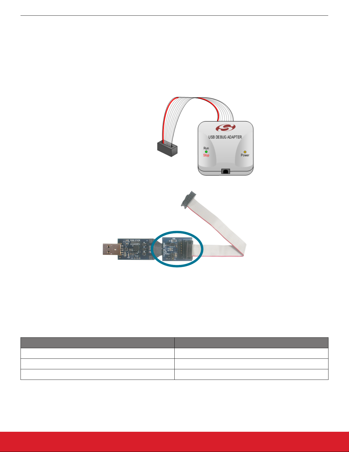
The 8-bit USB Debug Adapter (DEBUGADPTR1-USB, available here: https://www.silabs.com/products/mcu/Pages/USBDebug.aspx) or
the ToolStick Debug Adapter (available at http://www.silabs.com/toolstick) can be used to program TouchXpress devices. These adapters provide a 2 x 5 0.1" header that can be connected to the custom PCB to program the TouchXpress device. If this header is too large
for the application system, three test points can be located on the edge of the PCB for use with an adapter cable.
USB
Debug
Adapter
ToolStick Debug Adapter
Figure 1.1. USB Debug Adapter and ToolStick Debug Adapter
The required connections to program a TouchXpress device with the USB Debug Adpater or ToolStick Debug Adapter are:
Table 1.1. Required Connections for USB Debug Adapter or ToolStick Debug Adapter Programming
TouchXpress Device Pin USB Debug Adapter or ToolStick Debug Adapter Pin
Config Clk TDI / C2CK (pin 7)
Config Data TCK / C2D (pin 4)
GND GND (Ground) (pins 2, 3, or 9)
More information on the USB Debug Adapter can be found in the USB Debug Adapter User Guide, which is available from the page
linked above. More information about the ToolStick Debug Adapter can be found in the ToolStick Debug Adapter User Guide, which is
linked on the ToolStick website (http://www.silabs.com/toolstick).
silabs.com | Smart. Connected. Energy-friendly. Rev. 0.1 | 1
Page 3
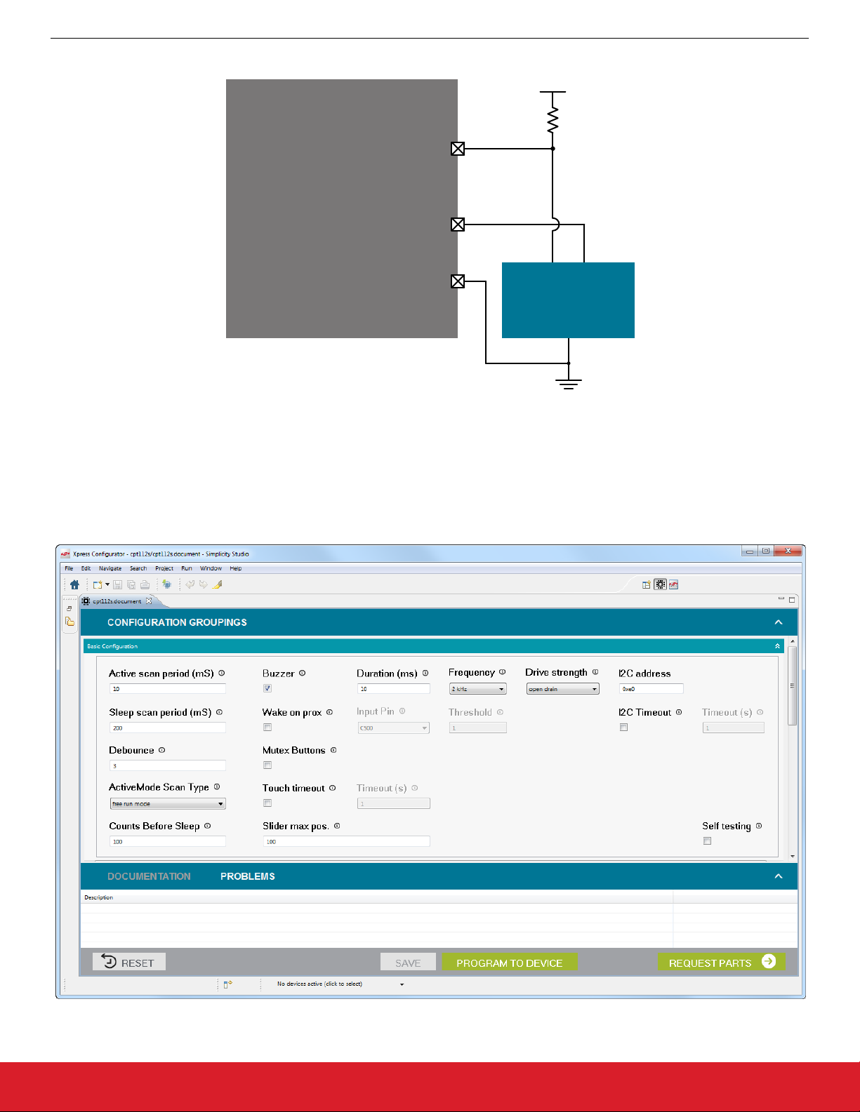
TouchXpress Device
Config Clk
Config Data
AN949: TouchXpress™ Programming Guide
In-System Programming
VDD
1 k
GND
USB Debug
Adapter or
Toolstick Debug
Adapter
Figure 1.2. Programming a TouchXpress Device with a USB Debug Adapter or ToolStick Debug Adapter
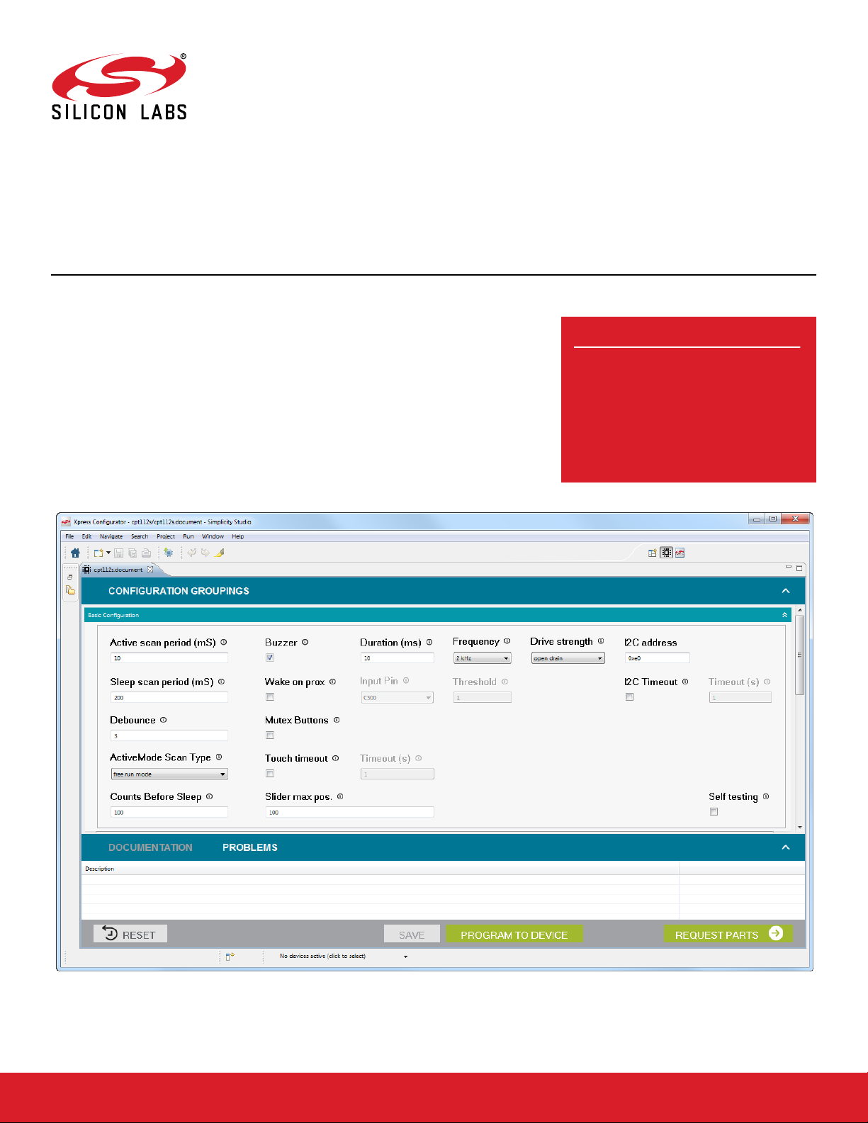
Systems using these debug adapters should use the [Xpress Configurator] tile in Simplicity Studio to program the devices. More information about [Xpress Configurator] is available in AN0829: "Capacitive Sensing Library Configuration Guide." Application notes can
be accessed within Simplicity Studio using the [Application Notes] tile or on the Silicon Labs website (www.silabs.com/interface-app-
notes).
Figure 1.3. Xpress Configurator in Simplicity Studio
silabs.com | Smart. Connected. Energy-friendly. Rev. 0.1 | 2
Page 4

AN949: TouchXpress™ Programming Guide
Pre-Programmed Devices
2. Pre-Programmed Devices
Pre-programmed devices are useful for end systems that do not provide access to the configuration pins on the device. Devices are
programmed before being installed in the end system. Pre-programming options include using a ToolStick programming socket, using a
third-party programmer, or using Silicon Labs’ in-house programming service.
2.1 Using a ToolStick Socket
The ToolStick sockets are available from http://www.silabs.com/toolstick. The ToolStick socket that's compatible with the CPT007B and
CPT112S TouchXpress devices is the ToolStick990MPP.
Figure 2.1. Example ToolStick Socket Board
The socket connects to a ToolStick Base Adapter. The following steps are initial setup instructions that must be completed once:
1. Download and install Simplicity Studio (http://www.silabs.com/simplicity) on the programming PC.
2. The auto-detect feature in Simplicity Studio can cause a CPT device to miss touches. First disable automatic detection by clicking
the [Settings] icon, selecting [Device Manager]>[TCF Device Discovery], and selecting [Never] for [USB Discovery Options].
Click [OK].
3. Ensure the socket switch is in the OFF position.
4. Connect the board to the ToolStick Base Adapter.
5. Connect the ToolStick Base Adapter to the PC.
The programming procedure for this socket is:
1. Place the TouchXpress device to be programmed into the socket, using the guide in the corner to ensure proper orientation.
2. Move the socket board switch to the ON position.
3. Click the [Refresh detected hardware] button in Simplicity Studio.
4. Select the device under [Detected Hardware].
5. Click the [Xpress Configurator] tile.
6. Load the desired configuration and click the [Program to Device] button.
7. Move the socket board switch to the OFF position.
8. Remove the device from the socket.
More information about [Xpress Configurator] is available in AN0829: "Capacitive Sensing Library Configuration Guide." Application
notes can be accessed within Simplicity Studio using the [Application Notes] tile or on the Silicon Labs website (www.silabs.com/inter-
face-appnotes).
silabs.com | Smart. Connected. Energy-friendly. Rev. 0.1 | 3
Page 5

AN949: TouchXpress™ Programming Guide
Pre-Programmed Devices
2.2 Third-Party Programmers
Support for Silicon Labs devices is being integrated into third-party production programmers from suppliers found on the Programming
Options page from the Silicon Labs website: https://www.silabs.com/products/mcu/Pages/ProgrammingOptions.aspx. Contact these
suppliers for more information about their programming solutions.
2.3 In-House Programming
For production orders, Silicon Labs offers a programming service for all TouchXpress devices. The pre-programmed devices can be
installed directly in the end system without providing access to the debug pins. Contact your local sales representative for more information about this service: http://www.silabs.com/buysample/Pages/contact-sales.aspx.
silabs.com | Smart. Connected. Energy-friendly. Rev. 0.1 | 4
Page 6

Simplicity Studio
One-click access to MCU and
wireless tools, documentation,
software, source code libraries &
more. Available for Windows,
Mac and Linux!
IoT Portfolio
www.silabs.com/IoT
Disclaimer
Silicon Laboratories intends to provide customers with the latest, accurate, and in-depth documentation of all peripherals and modules available for system and software implementers
using or intending to use the Silicon Laboratories products. Characterization data, available modules and peripherals, memory sizes and memory addresses refer to each specific
device, and "Typical" parameters provided can and do vary in different applications. Application examples described herein are for illustrative purposes only. Silicon Laboratories
reserves the right to make changes without further notice and limitation to product information, specifications, and descriptions herein, and does not give warranties as to the accuracy
or completeness of the included information. Silicon Laboratories shall have no liability for the consequences of use of the information supplied herein. This document does not imply
or express copyright licenses granted hereunder to design or fabricate any integrated circuits. The products must not be used within any Life Support System without the specific
written consent of Silicon Laboratories. A "Life Support System" is any product or system intended to support or sustain life and/or health, which, if it fails, can be reasonably expected
to result in significant personal injury or death. Silicon Laboratories products are generally not intended for military applications. Silicon Laboratories products shall under no
circumstances be used in weapons of mass destruction including (but not limited to) nuclear, biological or chemical weapons, or missiles capable of delivering such weapons.
Trademark Information
Silicon Laboratories Inc., Silicon Laboratories, Silicon Labs, SiLabs and the Silicon Labs logo, CMEMS®, EFM, EFM32, EFR, Energy Micro, Energy Micro logo and combinations
thereof, "the world’s most energy friendly microcontrollers", Ember®, EZLink®, EZMac®, EZRadio®, EZRadioPRO®, DSPLL®, ISOmodem ®, Precision32®, ProSLIC®, SiPHY®,
USBXpress® and others are trademarks or registered trademarks of Silicon Laboratories Inc. ARM, CORTEX, Cortex-M3 and THUMB are trademarks or registered trademarks of
ARM Holdings. Keil is a registered trademark of ARM Limited. All other products or brand names mentioned herein are trademarks of their respective holders.
Silicon Laboratories Inc.
400 West Cesar Chavez
Austin, TX 78701
USA
SW/HW
www.silabs.com/simplicity
Quality
www.silabs.com/quality
Support and Community
community.silabs.com
http://www.silabs.com
 Loading...