


Silicon Laboratories TOOLSTICK C8051F850, TOOLSTICK850-B-DC User Manual
TOOLSTICK850DC-UG
TOOLSTICK C8051F850 DAUGHTER CARD USER’S GUIDE
1. Handling Recommendations
To enable development, the ToolStick Base Adapter and daughter cards are distributed without any protective
plastics. To prevent damage to the devices and/or the host PC, consider the following recommendations when
using the ToolStick:
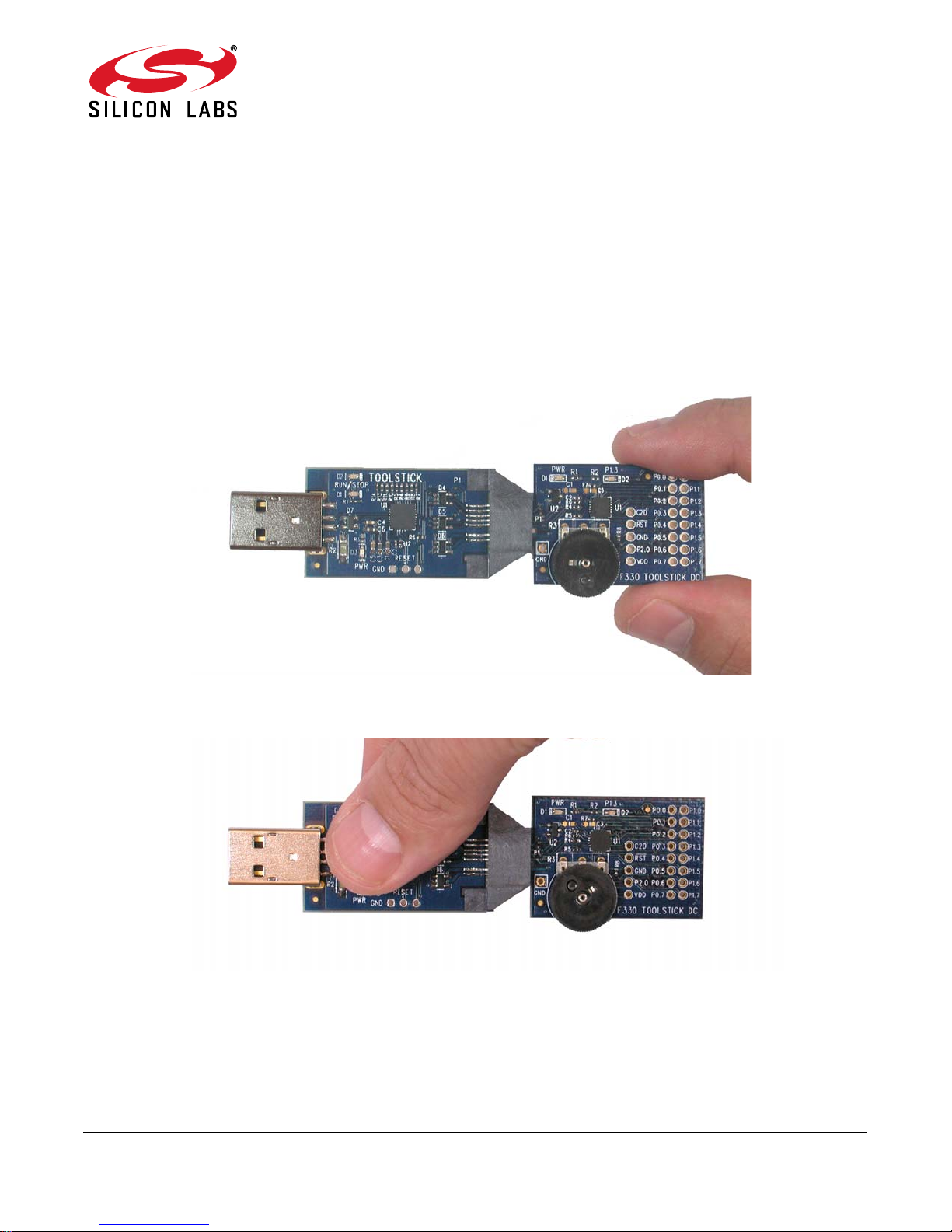
Never connect or disconnect a daughter card to or from th e ToolS tick Ba se Adapter while the Base Adapter
is connected to a PC.
Always connect and disconnect the ToolStick Base Adapter from the PC by holding the edges of the
boards.
Figure 1. Proper Method of Holding the ToolStick
Avoid directly touching any of the other components.
Figure 2. Improper Method of Holding the ToolStick
Manipulate mechanical devices on the daughter cards, such as potentiometers, with care to prevent the
Base Adapter or daughter card from accidentally dislodging from their sockets.
Rev. 0.2 2/14 Copyright © 2014 by Silicon Laboratories ToolStick-F850DC
TOOLSTICK850DC-UG
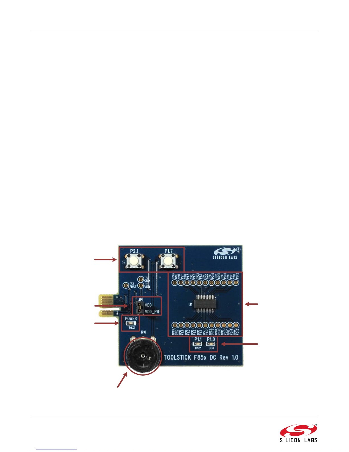
Potentiometer
Push-Button
Switches
LEDs
Power LED
Current Measure
Jumper
C8051F850 and
Port Access
2. Contents
The C8051F850 ToolStick Daughter Card kit (TOOLSTICK850-B-DC) contains the following items:
ToolStick C8051F850 Daughter Card (TOOLSTICK850DC)
A ToolStick daughte r card requires a ToolStick Base Adapter to communicate with the PC. ToolStick Ba se Adapters
can be purchased at www.silabs.com/toolstick.
The C8051F850 ToolStick Starter Kit (TOOLSTICK850-B-SK) contains the following items:
ToolStick C8051F850 Daughter Card (TOOLSTICK850DC)
ToolStick Base Adapter (TOOLSTICKBA)
USB extension cable
3. ToolStick Overview
The purpose of the ToolStick is to provide a development and demonstration platform for Silicon Labs
microcontrollers and to demonstrate the Silicon Labs Simplicity Studio software tools.
The ToolStick development platform consists of two components: the ToolStick Base Adapter and a daughter card.
The ToolStick Base Adapter provides a USB debug interface and data communications path between a Windows
PC and a target microcontroller.
The target microcontroller and application circuitry are located on the daughter card. Some daughter cards, such
as the C8051F850 Daughter Card, are used as general-purpose development platforms for the target
microcontrollers and some are used to demonstrate a specific feature or application.
The C8051F850 Daughter Card includes a p air of GPIO-c ontrolled L EDs, a potentiometer, two switches connected
to GPIO, and a small prototyping area which provides access to all of the pins of the device. This prototyping area
can be used to connect additional har dware to the microcontroller and use the daughter card as a development
platform.
Figure 3 shows the ToolStick C8051F850 Daughter Card and identifies the various components.
Figure 3. ToolStick C8051F850 Daughter Card
2 Rev. 0.2
TOOLSTICK850DC-UG
4. Getting Started
The necessary software to download, debug, and communicate with the target microcontroller must be
downloaded from www.silabs.com/toolstick. The following software is necessary to build a project, download code
to, and communicate with the target microcontroller:
Simplicity Studio
Keil C51 Tools
ToolStick Development Tools
The software described above is provided in the Simplicity Studio and 8-bit microcontroller studio download
packages. The ToolStick Development Tools selection includes example code specifically for the ToolStick
daughter card, documentation including user ’s guides and data sheets, and the ToolStick Terminal application.
After downloading and installing these packages, see the following sections for information regarding the software
and running one of the demo applications.
5. Software Overview
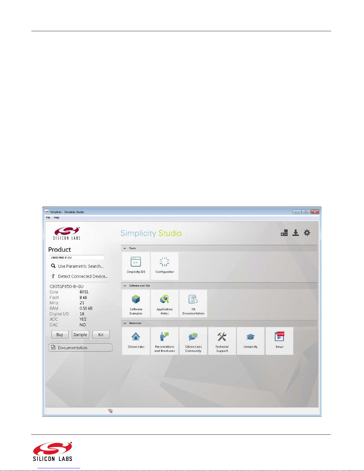
Simplicity Studio greatly reduces development time and complexity with Silicon Labs EFM32 and 8051 MCU
products by providing a high-powered IDE, tools for hardware configuration, and links to helpful resources, all in
one place.
Once Simplicity Studio is installed, the application itself can be used to install additional software and
documentation components to aid in the development and evaluation process.
Figure 4. Simplicity Studio
Rev. 0.2 3
TOOLSTICK850DC-UG
The following Simplicity Studio components are required for the C8051F850 ToolStick Starter Kit:
8051 Products Part Support
Simplicity Developer Platform
Download and install Simplicity Studio from www.silabs.com/8bit-software or www.silabs.com/simplicity-studio.
Once installed, run Simplicity Studio by selecting St art
from the start menu or clicking the Simplicity Studio shortcut on the desktop. Follow the instructions to install the
software and click Simplicity IDE to launch the IDE.
The first time the project creation wizard runs, the Setup Environment wizard will guide the user through the
process of configuring the build tools and SDK selection.
In the Part Selection step of the wizard, select from the list of installed parts only the parts to use during
development. Choosing parts and families in this step affects the displayed or filtered parts in the later device
selection menus. Choose the C8051F85x family by checking the C8051F85x/86x check box. Modify the part
selection at any time by accessing the Part Management dialog from the Window
Studio
Simplicity Studio can detect if certain toolchains are not activated. If the Licensing Helper is displayed after
completing the Setup Environment wizard, follow the instructions to activate the toolchain.
Part Management menu item.
5.1. Running Blinky
Each project has its own source files, target configuration, SDK configuration, and build configurations such as the
Debug and Release build configurations. The IDE can be used to manage multiple projects in a collection called a
workspace. Workspace settings are applied globally to all projects within the workspace, and can include settings
such as key bindings, window preferen ces, and code style and formatting options. Pro ject actions such as build
and debug are context sensitive. For example, the user must select a project in the Project Explorer view in order
to build that project.
To create a project based on the Blinky example:
1. Click the Simplicity IDE tile from the Simplicity Studio home screen.
2. Click the Create new project link from the welcome screen or go to File
Project.
3. In the Kit drop-down, select C8051F850 To olStick Starter Kit, in the Part drop-down, select C8051F850,
and in the SDK drop-down, select the desired SDK. Click Next.
4. Select Example and click Next.
5. Under C8051F850 ToolStick Starter Kit in the Blinky folder, select F85x-86x Blinky and click Finish.
6. Click on the project in the Project Explorer and click Build, the hammer icon in the top bar. Alternatively,
go to Project
7. Click Debug to download the project to the hardware and start a debug session.
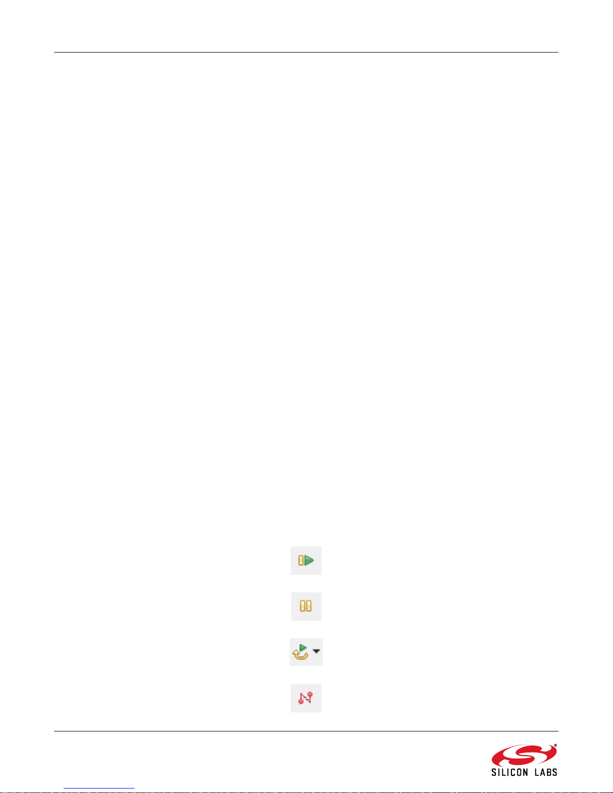
8. Press the Resume button to start the code running. The LED should blink.
Build Project.
Silicon LabsSimplicity StudioSimplicity Studio
PreferencesSimplicity
NewSilicon Labs MCU
9. Press the Suspend button to stop the code.
10. Press the Reset the device button to reset the target MCU.
11. Press the Disconnect button to return to the development perspective.
4 Rev. 0.2