

Silicon Laboratories ToolStick-F330DC, TOOLSTICK C8051F330, ToolStick-F540DC, TOOLSTICK C8051F540, ToolStick-F560DC User Manual
...
ToolStick-F330DC
TOOLSTICK C8051F330 DAUGHTER CARD USER ’S GUIDE
1. Handling Recommendations
To enable development, the ToolStick Base Adapter and daughter cards are distributed without any protective
plastics. To prevent damage to the devices and/or the host PC, please take into consideration the following
recommendations when using the ToolStick:
Never connect or disconnect a daughter card to or from the ToolStick Base Adapter while the Base Adapter is
connected to a PC.
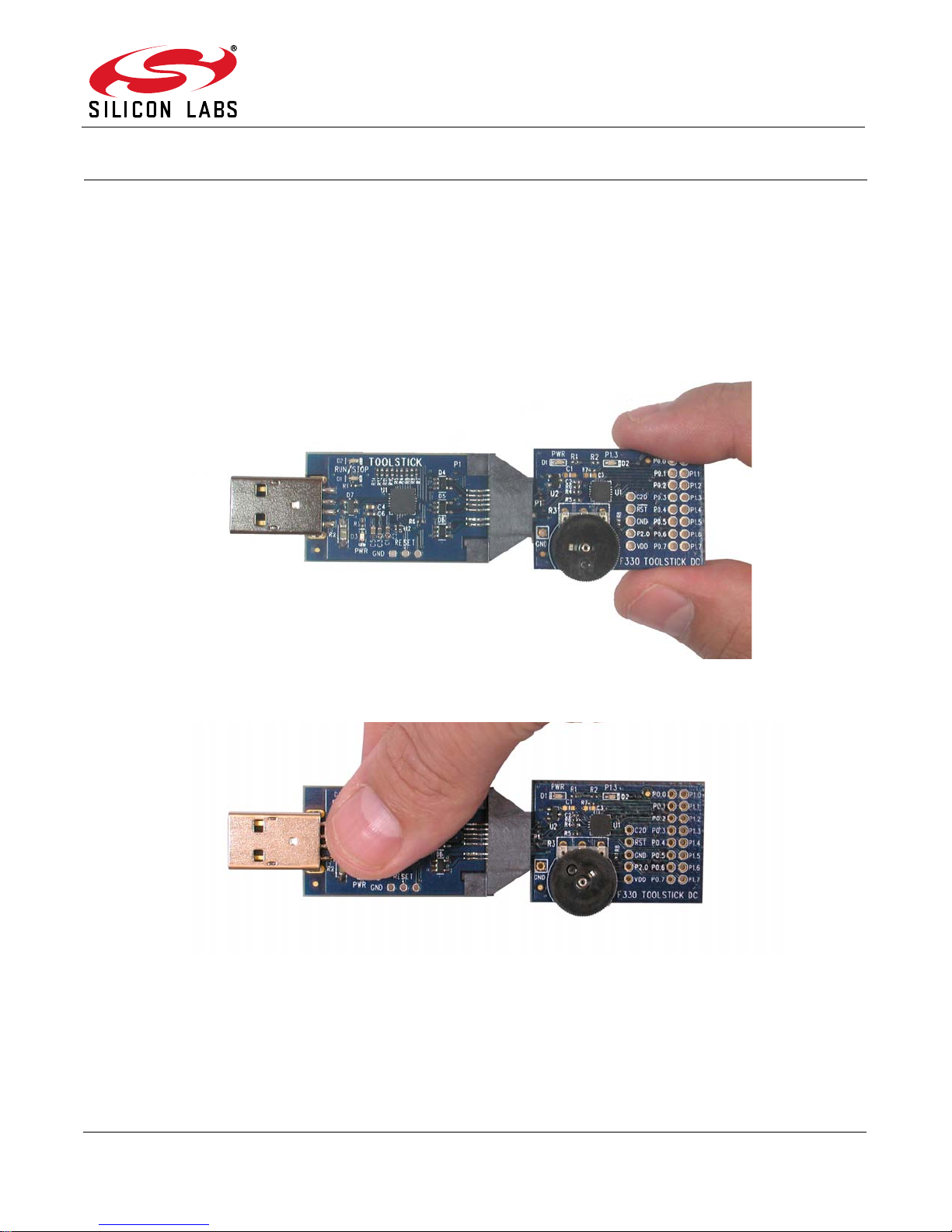
Always connect and disconnect the ToolStick Base Adapter fr om the PC by holding the edges of the boards.
Figure 1. Proper Method of Holding the ToolStick
Avoid directly touching any of the other components.
Figure 2. Improper Method of Holding the ToolStick
Manipulate mechanical devices on the daughter cards, such as potentiometers, with care to prevent the Base
Adapter or daughter card from accidentally dislodging from their sockets.
Rev. 0.4 5/14 Copyright © 2014 by Silicon Laboratories ToolStick-C8051F330DC
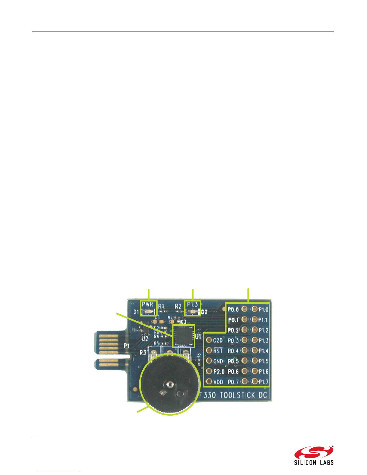
ToolStick-F330DC
Power LED P1.3 LED
C8051F330
P1.6 Potentiometer
Full Pin Access
2. Contents
The C8051F330 ToolStick DC (TOOLSTICK330DC) kit contains the following items:
ToolStick C8051F330 Daughter Card
The ToolStick Starter Kit (TOOLSTICKSK) includes the following items:
ToolStick Base Adapter
ToolStick C8051F330 Daughter Card
3-foot USB extension cable
A ToolStick daughter card require s a ToolStick Base Adapter to communicate with the PC. If the da ughter card was
not purchased as part of a Starter Kit, ToolStick Base Adapters can be purchased separately at
www.silabs.com/toolstick.
3. ToolStick Overview
The purpose of the ToolStick is to provide a development and demonstration platform for Silicon Laboratories
microcontrollers and to demonstrate the Silicon Laboratories software tools, including the Integrated Development
Environment (IDE).
The ToolStick development platform consists of two components: the ToolStick Base Adapter and a daughter card.
The ToolStick Base Adapter provides a USB debug interface and data communications path between a Windows
PC and a target microcontroller.
The target microcontroller and application circuitry are located on the daughter card. Some daughter cards, such
as the C8051F330 Daughter Card, are used as general-purpose development platforms for the target
microcontrollers and some are used to demonstrate a specific feature or application.
The C8051F330 Daughter Card includes a pair of LEDs, a potentiometer, a resistor across the C8051F330’s
current DAC output pin, and a small prototyping area which provides access to all of the pins of the device. This
prototyping area can be used to connect additional har dwar e to th e micr ocontroller and u se the dau ghte r card a s a
development platform. See Section "7. Board Revision Information‚" on page 7 for information regarding the
prototyping area.
Figure 3 shows the ToolStick C8051F330 Daughter Card and identifies the various components.
Figure 3. ToolStick C8051F330 Daughter Card
2 Rev. 0.4
ToolStick-F330DC
4. Getting Started
The necessary software to download, de bug and communicate with the t a rget micr ocontroller m ust be do wnloaded
from www.silabs.com/toolstick. The following software is necessary to build a project, download code to, and
communicate with the target microcontroller:
Simplicity Studio
Keil C51 Tools
ToolStick Development Tools
The software described above is provided in the Simplicity Studio and 8-bit microcontroller studio download
packages. The ToolStick Development Tools selection includes example code specifically for the ToolStick
daughter card, documentation including user ’s guides and data sheets, and the ToolStick Terminal application.
After downloading and installing these packages, see the following sections for information regarding the software
and running one of the demo applications.
5. Software Overview
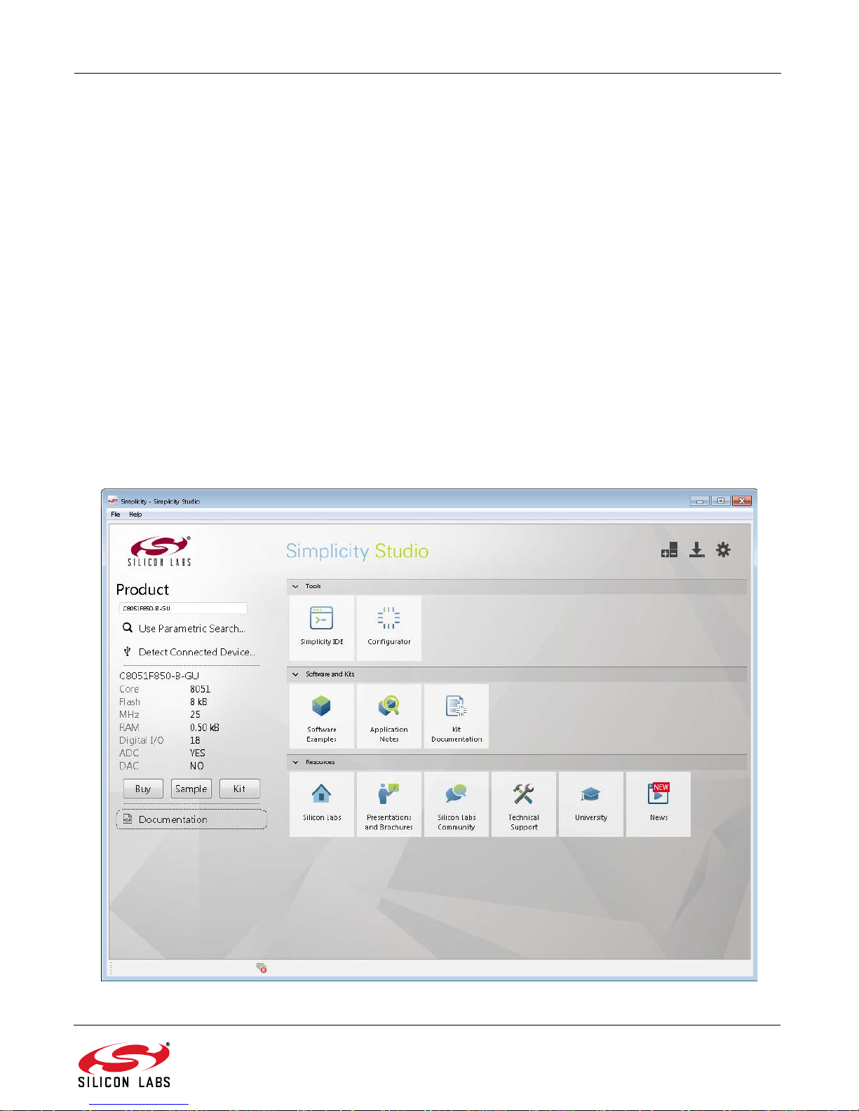
Simplicity Studio greatly reduces development time and complexity with Silicon Labs EFM32 and 8051 MCU
products by providing a high-powered IDE, tools for hardware configuration, and links to helpful resources, all in
one place.
Once Simplicity Studio is installed, the application itself can be used to install additional software and
documentation components to aid in the development and evaluation process.
Figure 4. Simplicity Studio
Rev. 0.4 3
 Loading...